JP2019082003A - Direction control system of shield machine - Google Patents
Direction control system of shield machine Download PDFInfo
- Publication number
- JP2019082003A JP2019082003A JP2017208559A JP2017208559A JP2019082003A JP 2019082003 A JP2019082003 A JP 2019082003A JP 2017208559 A JP2017208559 A JP 2017208559A JP 2017208559 A JP2017208559 A JP 2017208559A JP 2019082003 A JP2019082003 A JP 2019082003A
- Authority
- JP
- Japan
- Prior art keywords
- actual
- force point
- shield machine
- recommended
- regression analysis
- Prior art date
- Legal status (The legal status is an assumption and is not a legal conclusion. Google has not performed a legal analysis and makes no representation as to the accuracy of the status listed.)
- Granted
Links
- 238000000611 regression analysis Methods 0.000 claims abstract description 58
- 238000004364 calculation method Methods 0.000 claims description 18
- 230000009471 action Effects 0.000 claims description 13
- 238000005553 drilling Methods 0.000 abstract description 16
- 238000010276 construction Methods 0.000 description 10
- 230000005484 gravity Effects 0.000 description 8
- 238000012545 processing Methods 0.000 description 8
- 230000008859 change Effects 0.000 description 7
- 230000005540 biological transmission Effects 0.000 description 6
- 238000000034 method Methods 0.000 description 4
- 238000005259 measurement Methods 0.000 description 3
- 239000002689 soil Substances 0.000 description 3
- 238000005452 bending Methods 0.000 description 2
- 230000006870 function Effects 0.000 description 2
- 230000004044 response Effects 0.000 description 2
- 238000009825 accumulation Methods 0.000 description 1
- 238000013459 approach Methods 0.000 description 1
- 238000009412 basement excavation Methods 0.000 description 1
- 230000008602 contraction Effects 0.000 description 1
- 230000003111 delayed effect Effects 0.000 description 1
- 238000010586 diagram Methods 0.000 description 1
- 238000012986 modification Methods 0.000 description 1
- 230000004048 modification Effects 0.000 description 1
- 238000012544 monitoring process Methods 0.000 description 1
- 230000002093 peripheral effect Effects 0.000 description 1
- 238000002360 preparation method Methods 0.000 description 1
- 239000004065 semiconductor Substances 0.000 description 1
- 230000002194 synthesizing effect Effects 0.000 description 1
- XLYOFNOQVPJJNP-UHFFFAOYSA-N water Substances O XLYOFNOQVPJJNP-UHFFFAOYSA-N 0.000 description 1
Images




Landscapes
- Excavating Of Shafts Or Tunnels (AREA)
Abstract
Description
本発明は、シールド掘進機の掘進方向を制御するための、シールド掘進機の方向制御システムに関する。 The present invention relates to a direction control system of a shield machine for controlling the direction of the shield machine.
シールド施工の省力化や操作の簡略化等を目的として、例えば、特許文献1には、シールド掘進機にシールドジャッキによるジャッキ推力を作用させる際の作用力点を用いて、シールド掘進機の掘進方向を制御するための、シールド掘進機の方向制御システムおよび方向制御方法が開示されている。 For the purpose of labor saving of shield construction and simplification of operation etc., for example, Patent Document 1 uses the action force point when the jack thrust by the shield jack is applied to the shield digging machine, the digging direction of the shield digging machine is SUMMARY OF THE INVENTION A directional control system and method of a shield machine for controlling is disclosed.
特許文献1では、円盤状のカッターヘッドと、該カッターヘッドの縁部に沿って配置される複数のシールドジャッキと、を備える複数のシールド掘進機において、正面視で左右端に位置するシールドジャッキの伸縮量の差をストローク差、上下端方向のシールド掘進機の傾斜角度をピッチング角として設定する。 In Patent Document 1, a plurality of shield machines including a disk-shaped cutter head and a plurality of shield jacks disposed along the edge of the cutter head, the shield jacks positioned at the left and right ends in a front view The difference between the amounts of expansion and contraction is set as the stroke difference, and the inclination angle of the shield machine in the upper and lower end direction is set as the pitching angle.
そのうえで、所定区間だけ掘進して停止させたシールド掘進機の現在のストローク差およびピッチング角を計測するとともに、作業員が、次の所定区間の掘進作業に向けて、シールド掘進機を計画線形に近づけるための目標ストローク差および目標ピッチング角を適宜設定する。この後、目標ストローク差と現在のストローク差の差分(以降、SJストローク差の変化量)と過去の「実績による学習直線」から、カッターヘッドの左右端方向のSJ重心位置を求める。同様に、目標ピッチングと現在のピッチング角(ピッチング角の変化量)の差分と過去の「実績による学習直線」から、カッターヘッドの上下端方向のSJ重心位置を求める。 Then, the current stroke difference and pitching angle of the shield machine which has been drilled and stopped for a predetermined section are measured, and the operator brings the shield machine closer to the planned linear shape for the next predetermined section drilling work. The target stroke difference and the target pitching angle are appropriately set. After this, the SJ gravity center position in the left and right end direction of the cutter head is obtained from the difference between the target stroke difference and the current stroke difference (hereinafter referred to as the SJ stroke difference change amount) and the past "learned by actual results". Similarly, from the difference between the target pitching and the current pitching angle (the amount of change in the pitching angle) and the past "learned by actual results", the SJ gravity center position in the upper and lower end direction of the cutter head is determined.
上記の2方向各々におけるSJ重心位置を合成することにより得られる合成SJ重心位置は、シールド掘進機を計画線形に近づけるために最適なジャッキ推力の作用力点となる。そこで、次の所定区間の掘進作業は、この合成SJ重心位置と最も近い重心位置となるジャッキパターンを適宜選択し、選択したジャッキパターンにて再開すればよい。 The combined SJ center-of-gravity position obtained by combining the SJ center-of-gravity positions in each of the two directions described above is an action force point of jack thrust that is optimal for bringing the shield machine closer to the planned linear. Therefore, the digging work for the next predetermined section may be appropriately selected from the jack pattern which is the center of gravity position closest to the combined SJ center of gravity position, and resumed with the selected jack pattern.
特許文献1によれば、目標ストローク差及び目標ピッチング角を作業員が設定するなど、人間の判断を取り入れつつ、コンピュータを用いてシールド掘進機の方向制御を行うことが可能となる。 According to Patent Document 1, it is possible to control the direction of the shield machine using a computer while taking human judgment such as setting a target stroke difference and a target pitching angle.
しかし、特許文献1において、カッターヘッドの左右端方向のSJ重心位置および上下端方向のSJ重心位置を求める際に用いる「実績による学習直線」は、制御実績の参照範囲をあらかじめ設定し(例えば、現在から過去30リング分等)、この参照範囲の制御実績データを用いて行った回帰分析結果を利用している。 However, in Patent Document 1, the “Study track by performance” used when obtaining the SJ center of gravity position in the left and right end direction and the SJ center of gravity in the upper and lower end direction of the cutter head sets a reference range of control results beforehand From the present to the past 30 rings, etc.), the results of regression analysis performed using control actual data in this reference range are used.
このため、制御実績の参照範囲として地盤状況を的確に捉えた範囲が必ずしも設定されていない場合が想定され、上記2方向のSJ重心位置を合成して得た合成SJ重心位置の信頼性に課題が生じる。また、掘進途中で地盤が変化する場合には、制御実績の参照範囲が広すぎると、地盤変化への対応に遅れが生じることも考えられる。 For this reason, the case where the range which caught ground condition correctly as a reference range of control results is not necessarily set up is assumed, and the subject of the reliability of the synthetic SJ gravity center position obtained by synthesizing the SJ gravity center position of said 2 directions Will occur. In addition, when the ground changes during digging, if the reference range of the control results is too wide, it may be considered that the response to the ground change may be delayed.
本発明は、かかる課題に鑑みなされたものであって、その主な目的は、高い信頼性を確保しつつ簡略な操作により、シールド掘進機の掘進方向を制御することの可能な、シールド掘進機の方向制御システムを提供するものである。 The present invention has been made in view of such problems, and the main object of the present invention is to provide a shield machine capable of controlling the direction in which the shield machine is advanced by a simple operation while securing high reliability. Provides a directional control system of
かかる目的を達成するため、本発明のシールド掘進機の方向制御システムは、シールド掘進機に作用するジャッキ推力の作用力点を用いて、該シールド掘進機の掘進方向を制御するための、シールド掘進機の方向制御システムであって、所定区間を掘進するごとに、少なくとも、前記シールド掘進機の実績ストローク差と実績ピッチング角度差、および前記ジャッキ推力から計算される、前記シールド掘進機の軸線を通る水平方向線上の実績水平力点と垂直方向線上の実績垂直力点を算出および記録する掘進管理/線形管理装置と、前記シールド掘進機を計画線形に沿うよう掘進させるべく、前記作用力点として推奨する推奨力点を、推奨水平力点と推奨垂直力点の合力から算出する方向制御装置と、を備え、前記方向制御装置が、前記掘進管理/線形管理装置から得た前記実績ストローク差と前記実績水平力点の回帰分析、前記実績ピッチング角度差と実績垂直力点の回帰分析をそれぞれ、データ数を変更して複数回実施する回帰分析結果取得手段と、該回帰分析結果取得手段で得た複数の回帰分析結果のうち、適宜選択された前記データ数に基づく前記実績ストローク差と前記実績水平力点の回帰分析結果に基づいて前記推奨水平力点を、また、適宜選択された前記データ数に基づく前記実績ピッチング角度差と前記実績垂直力点の回帰結果に基づいて前記推奨垂直力点を、それぞれ算出する力点位置算出手段と、を備えることを特徴とする。 In order to achieve such an object, the direction control system of the shield machine according to the present invention is a shield machine for controlling the direction of the shield machine by using the point of action of the jack thrust acting on the shield machine. A direction control system, wherein the horizontal travel through the axis of the shield machine, calculated from the actual stroke difference and the actual pitching angle difference of the shield machine and the jack thrust, each time a predetermined section is drilled A drilling management / linear management device that calculates and records actual horizontal force points on the direction line and actual vertical point on the vertical direction, and recommended force points recommended as the action points to dig the shield machine along the planned linearity A direction control device which is calculated from the resultant force of the recommended horizontal force point and the recommended vertical force point, and the direction control device Regression analysis of the actual stroke difference and the actual horizontal force point obtained from the logical / linear management device, and the regression analysis of the actual pitching angle difference and the actual vertical force point respectively, multiple regression analysis results obtained by changing the number of data And said plurality of regression analysis results obtained by said regression analysis result acquisition means, said recommended horizontal force point based on a result of regression analysis result of said actual stroke difference and said actual horizontal force point based on said data number appropriately selected. In addition, force point position calculation means for calculating the recommended vertical force point on the basis of the actual pitching angle difference based on the data number appropriately selected and the regression result of the actual vertical force point is provided. .
上述する本発明のシールド掘進機の方向制御システムによれば、回帰分析結果取得手段にて、実績ストローク差と実績水平力点の回帰分析および実績ピッチング角度差と実績垂直力点の回帰分析が、いずれもデータ数を変更して複数回実施される。これにより、例えば、掘進する区間が地盤に変化が生じた直後である場合には、推奨水平力点および推奨垂直力点の算出にそれぞれ、複数の回帰分析結果の中から直近の最も少ないデータ数を用いて算出した回帰分析結果を選択でき、地盤の変化に対して迅速に対応した推奨力点を算出することが可能となる。 According to the direction control system of the shield machine of the present invention described above, regression analysis result acquisition means, regression analysis of actual stroke difference and actual horizontal force point and regression analysis of actual pitching angle difference and actual vertical force point The number of data is changed and implemented multiple times. Thus, for example, when the section to be drilled is immediately after a change occurs in the ground, each of the plurality of regression analysis results is used to calculate the recommended horizontal force point and the recommended vertical force point. It is possible to select the regression analysis result calculated in this way, and to calculate the recommended force points that correspond quickly to the change of the ground.
本発明のシールド掘進機の方向制御システムは、前記力点位置算出手段では、前記推奨水平力点及び前記推奨垂直力点各々の算出に用いる前記回帰分析結果に、最も高い相関係数を得た前記データ数に基づく前記回帰分析結果を選択することを特徴とする。 In the direction control system of a shield machine according to the present invention, in the force point position calculation means, the number of data that has obtained the highest correlation coefficient in the regression analysis result used for calculating each of the recommended horizontal force point and the recommended vertical force point. Selecting the result of the regression analysis based on.
上述する本発明のシールド掘進機の方向制御システムによれば、推奨水平力点および推奨垂直力点を算出するにあたり、複数の中から最も高い相関係数を得た前記データ数に基づく回帰分析結果を採用する。これにより、シールド掘進機を計画線形に沿うよう掘進させるための作用力点として推奨する推奨力点の信頼性が高まるとともに、シールド掘進機の方向制御に係る正確性を向上させることが可能となる。 According to the direction control system of the shield machine of the present invention described above, when calculating the recommended horizontal force point and the recommended vertical force point, the regression analysis result based on the number of data obtained the highest correlation coefficient among the plurality is adopted. Do. This makes it possible to increase the reliability of the recommended power point recommended as a working power point for digging the shield machine along the planned line, and to improve the accuracy of direction control of the shield machine.
また、シールド掘進機のオペレータは、方向制御システムにて設定された推奨力点を参照しつつ、シールド掘進機の性能等を考慮して、シールド掘進機に作用させようとするジャッキ推力の目標力点を決定でき、シールド掘進機の制御に係る作業を簡略化することが可能となる。 Also, the operator of the shield machine refers to the recommended power point set by the direction control system, and in consideration of the performance of the shield machine etc., the target power point of the jack thrust to be applied to the shield machine. It is possible to determine and simplify the work related to the control of the shield machine.
本発明によれば、シールド掘進機が計画線形から大きく逸脱することのないよう、シールド掘進機を掘進させるための作用力点として推奨する推奨力点を設定できるため、簡略な操作により高い信頼性を確保しつつ、シールド掘進機の掘進方向を制御することが可能となる。 According to the present invention, it is possible to set a recommended force point recommended as a working force point for digging the shield drilling machine so that the shield drilling machine does not deviate significantly from the planned linearity, so high reliability is ensured by a simple operation. In addition, it is possible to control the drilling direction of the shield machine.
本発明のシールド掘進機の方向制御システムは、シールド掘進機の掘進方向を、シールド掘進機に作用させるジャッキ推力の作用力点を用いて制御するものである。以下に、本発明のシールド掘進機の方向制御システムを、シールド掘進機の構成と併せて、図1〜12を参照しながら説明する。 The direction control system of the shield construction machine of the present invention controls the construction direction of the shield construction machine using the point of action of jack thrust acting on the shield construction machine. Hereinafter, the direction control system of the shield machine according to the present invention will be described in conjunction with the configuration of the shield machine with reference to FIGS.
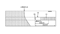
シールド掘進機10は、図1の側面図および図4の正面図で示すように、先端面にカッターディスク25を備えた筒状の外殻体11と、外殻体11の内周面に沿って周方向に設けられる複数のシールドジャッキ14を備える。これらは、カッターディスク25を回転させて地盤を掘進しつつ、外殻体11の内部で組み立てたトンネル12の内壁面を覆うセグメント13を掘進反力にして、シールドジャッキ14のジャッキ推力を用いてシールド掘進機10を推進させる動作を繰り返し、順次掘進作業を行ってゆく。
As shown in the side view of FIG. 1 and the front view of FIG. 4, the
また、シールド掘進機10には、その内部に、コンピュータからなり、シールド掘進機10の駆動制御を実行するシールド制御装置15と、シールド掘進機10の位置測量や計測を行うための計測機器として、自動測量機能が備えられている場合には、少なくともレーザー発振機16、光波距離計17、およびレーザーターゲット18が装備されている。なお、自動測量機能が備えられていない場合は、水平方向はジャイロとストローク計により、垂直方向は水レベル計とピッチング計により、シールド掘進機10の位置の演算を実施する。
Further, the
このような計測機器は、地上に設けられたコンピュータからなる掘進管理/線形管理装置20と接続されており、掘進管理/線形管理装置20では、上記の計測機器から得た掘進作業中の各種データの収集・計算・記録・蓄積を行うとともに、シールド掘進機10の稼働状況の監視する。また、シールド掘進機10の位置・姿勢および施工計画に基づく計画線形Lに対する逸脱量を把握して、シールド掘進機10の線形管理を行う。
Such a measuring device is connected to a digging management /
シールド掘進機10の方向制御システム100は、上記の掘進管理/線形管理装置20と、これに接続される方向制御装置30とを備えており、方向制御装置30は、図2で示すように、入力装置31と、出力装置32と、中央演算処理装置33と、ファイル装置34と、メインメモリ35とを備えている。
The
入力装置31は、例えばキーボード、スキャナー、スイッチ等であり、出力装置32は、ディスプレイやプリンター等が挙げられる。中央演算処理装置33は、CPU、GPU、ROM、RAM及びハードウェアインタフェース等を有するコンピュータである。また、ファイル装置34は、半導体メモリ又はハードディスクドライブ等からなる記憶装置であり、後に詳細を述べるが、少なくとも測量ファイル341、回帰分析結果格納ファイル342、およびジャッキパターンテーブルファイル343が格納されている。
The
メインメモリ35は、中央演算処理装置33によって実行可能なプログラムやデータを一時的に格納するものであり、後に詳細を述べるが、少なくも実目標値算出部351、回帰分析結果取得部352、力点位置算出部353、およびジャッキパターン選択部354が備えられている。そして、上述する構成の方向制御装置30は、多重伝送装置親局21および多重伝送装置子局22を介して、シールド制御装置15と接続されている。
The
このように、方向制御装置30を介してシールド制御装置15と方向制御システム100とを連携させて、施工計画に基づく計画線形Lからシールド掘進機10が大きく逸脱することのないよう、シールド掘進機10が所定区間を掘進するごとに、その掘進方向を制御する。具体的には、シールド掘進機10を計画線形Lに沿うよう掘進させるべく、シールド掘進機10に作用するジャッキ推力の作用力点として推奨する推奨力点を方向制御システム100を用いて算出し、この推奨力点を用いてシールド掘進機10の掘進方向をシールド制御装置15にて制御する。
In this manner, the
以下に、方向制御システム100の詳細とシールド掘進機10の方向制御方法を、図3で示すフロー図にしたがって説明する。なお、本実施の形態では、シールド掘進機10が所定区間としてセグメント13の1リング分を掘進するごとに、計画線形Lからシールド掘進機10が逸脱することのないよう、掘進方向の制御を行う場合を事例に挙げ、説明する。
Hereinafter, the details of the
<STEP1>
シールド掘進機10により地盤をセグメント13の1リング分を掘進した後、シールド掘進機10を一旦停止させ、前述の計測機器を用いてシールド掘進機10の位置を計測し、掘進管理/線形管理装置20に記録する。
<STEP1>
After drilling the ground for one ring of the
また、前述の計測機器から得た計測結果に基づいて、シールド掘進機10の実績ストローク差、実績ピッチング角および実績ピッチング角度差を、掘進管理/線形管理装置20にて算出し記録する。
Further, based on the measurement result obtained from the above-described measurement device, the digging management /
なお、ストローク差は、シールド掘進機10の水平面内における左右方向の回転量であり、図4で示すような、シールド掘進機10の正面視で左右端に位置する一対のシールドジャッキ141の、伸長量から算定される。そして、実績ストローク差は、セグメント13の1リング分を掘進した後のストローク差をいう。
The stroke difference is the amount of rotation in the horizontal direction of the
ピッチング角は、図4で示すような複数のシールドジャッキ14のうち、上下端に位置するシールドジャッキ142のストローク差から算出、あるいはシールド掘進機10に装備されている計測機器により測定される。そして、実績ピッチング角は、セグメント13の1リング分を掘進した後のピッチング角、実績ピッチング角度差は、セグメント13の1リング分を掘進した前後のピッチング角の差を、それぞれいう。
The pitching angle is calculated from the stroke difference of the shield jacks 142 located at the upper and lower ends of the plurality of shield jacks 14 as shown in FIG. 4 or is measured by a measuring device equipped in the
さらに、図4で示すように、シールド掘進機10に作用したシールドジャッキ14のジャッキ推力から、シールド掘進機10の軸線Oを通る水平方向線上の実績水平力点H1、垂直方向線上の実績垂直力点P1を、掘進管理/線形管理装置20にて算出し記録する。
Furthermore, as shown in FIG. 4, from the jack thrust of the
水平力点は、シールド掘進機10に作用した複数のシールドジャッキ14各々の、ジャッキ推力の合力に基づいて算出したシールド掘進機の軸線Oを通る水平方向線上の作用点であり、実績水平力点H1は、セグメント13の1リング分を掘進した後の水平力点をいう。また、垂直力点は、シールド掘進機10に作用した複数のシールドジャッキ14各々の、ジャッキ推力の合力に基づいて算出した、シールド掘進機の軸線Oを通る水平方向線と直交する垂直方向線上の作用点であり、実績垂直力点P1は、セグメント13の1リング分を掘進した後の垂直力点をいう。
The horizontal force point is a point of action on the horizontal direction line passing through the axis O of the shield machine, calculated based on the resultant force of the jack thrust, of each of the plurality of shield jacks 14 acting on the
これらシールド掘進機10の位置、実績ストローク差、実績ピッチング角、実績ピッチング角度差、実績水平力点H1および実績垂直力点P1の各データは、計測または算出されるごとに掘進管理/線形管理装置20に記録されるだけでなく方向制御装置30に送信され、ファイル装置34の測量ファイル341に格納・蓄積される。
The data of the position of the
上記の作業を繰り返し、各データが所定の数量蓄積されたところで、<STEP2>以降の作業を開始する。なお、本実施の形態では、掘進開始時からセグメント13の30リング分だけ各データを蓄積するまで、上述の作業を繰り返したが、各データの蓄積数量は、施工現場の地盤状況やシールド掘進機10の性能等に応じて、適宜決定すればよい。
The above-described work is repeated, and after each data has been accumulated in a predetermined quantity, the work after <STEP 2> is started. In the present embodiment, the above operation is repeated from the start of digging until each ring of 30 segments of
<STEP2>
シールド掘進機10の現在位置からシールド掘進機10の計画線形Lに対する逸脱量Dh、Dpを、掘進管理/線形管理装置20にて算定する。逸脱量Dhは、図5(a)で示すような計画線形Lに対するシールド掘進機10の水平方向のズレ量であり、逸脱量Dpは、図5(b)で示すような計画線形Lに対するシールド掘進機10の鉛直方向のズレ量である。
<STEP2>
From the current position of the
なお、シールド掘進機10の現在位置は、ファイル装置34の測量ファイル341に蓄積されている、シールド掘進機10の位置情報の最新値がこれに相当する。また、シールド掘進機10の計画線形Lに対する逸脱量Dh、Dpも、掘進管理/線形管理装置20から方向制御装置30に送信されることにより、ファイル装置34の測量ファイル341に格納・蓄積される。
The current position of the
算定した逸脱量Dh,Dpに基づいて、現場職員は、計画線形Lから逸脱したシールド掘進機10を、次の掘進作業で計画線形Lに戻しつつ沿わせるための進行計画を立案するとともに、進行計画を実現するためのストローク差とピッチング角の進行目標値、もしくはピッチング角度差の進行目標値(ピッチング角の現在値とピッチング角の進行目標値との差)を算出する。
Based on the calculated deviation amounts Dh and Dp, the field staff prepares a progress plan for returning the
具体的には、計画線形Lに戻しつつ沿わせるための予想線形を作成するとともに、予想線形にのせるためのシールド掘進機10の曲げ量を算出する。算出した曲げ量を生じさせるために必要なシールドジャッキ14のジャッキ推力を、垂直および水平方向のベクトル量として計算する。その計算結果から、このジャッキ推力を生じさせるための最適なストローク差とピッチング角、もしくはピッチング角度差(ピッチング角の現在値とジャッキ推力を生じさせるための最適なピッチング角との差)を算出する。これらを、ストローク差の進行目標値、およびピッチング角の進行目標値もしくはピッチング角度差の進行目標値として設定し、入力装置31を介して方向制御装置30に入力する。
Specifically, while creating a predicted linear shape for returning along the planned linear L, the bending amount of the
<実目標値算出部>
方向制御装置30に進行目標値が入力されたところで、中央演算処理装置33がメインメモリ35に格納されている実目標値算出部351の指令を受け、ファイル装置34の測量ファイル341に格納されている、ストロークの現在値を取り出し、これと進行目標値との差からストローク差の実目標値を算出する。同様に、ファイル装置34の測量ファイル341に格納されている、ピッチング角の現在値を取り出し、これと進行目標値(ピッチング角度差もしくはピッチング角)を参照し、ピッチング角度差の実目標値(目標ピッチング角度差)を算出する。
<Real target value calculation unit>
When the progress target value is input to the
なお、ストローク差およびピッチング角の現在値は各々、ファイル装置34の測量ファイル341に蓄積されている、実績ストローク差および実績ピッチング角の各々の最新値が、これに相当する。
The current values of the stroke difference and the pitching angle correspond to the latest values of the actual stroke difference and the actual pitching angle stored in the
<回帰分析結果取得部>
次いで、中央演算処理装置33がメインメモリ35に格納されている回帰分析結果取得部352の指令を受け、ファイル装置34の測量ファイル341に格納されている実績ストローク差と実績水平力点H1を用いて、両者の回帰分析をデータ数を変更して複数回実施する。同様に、ファイル装置34の測量ファイル341に格納した実績ピッチング角度差と実績垂直力点P1を用いて、両者の回帰分析をデータ数を変更して複数回実施する。
<Regression Analysis Result Acquisition Unit>
Next, the
本実施の形態では、<STEP2>を開始するまで<STEP1>の作業を30回繰り返し、セグメント13の30リング分だけ実績ストローク差と実績水平力点H1を蓄積している。そこで、回帰分析に用いるデータの数量を、30リング分のデータのうち、最新のデータから連続して(以降、直近という)10リング分、直近20リング分、および30リング分全部の3パターンを準備し、この3パターン各々で回帰分析を行った。
In the present embodiment, the operation of <STEP 1> is repeated 30 times until <STEP 2> is started, and the actual stroke difference and the actual horizontal force point H1 are accumulated by 30 rings of the
実績ストローク差と実績水平力点H1の回帰分析結果を、例えば図6(a)〜(c)のようなグラフとして、また、実績ピッチング角度差と実績垂直力点P1の回帰分析結果を、例えば図7(a)〜(c)のようなグラフとして、それぞれ出力装置32に出力する。これと同時に、ファイル装置34の回帰分析結果格納ファイル342にも、実績ストローク差と実績水平力点H1の回帰分析結果および実績ピッチング角度差と実績垂直力点P1の回帰分析結果を格納する。
The regression analysis results of the actual stroke difference and the actual horizontal force point H1 are, for example, graphs shown in FIGS. 6A to 6C, and the regression analysis results of the actual pitching angle difference and the actual vertical force point P1 are, for example, FIG. The graphs are output to the
<力点位置算出部>
実績ストローク差と実績水平力点H1の回帰分析結果、および実績ピッチング角度差と実績水平力点P1の回帰分析結果の各々について、中央演算処理装置33が、メインメモリ35に格納されている力点位置算出部353の指令を受け、3パターンの中から最も高い相関係数を得たデータ数に基づく回帰直線を選択する。
<Power point position calculation unit>
The
この後、次の掘進作業でシールド掘進機10を計画線形Lに戻しつつ沿うよう掘進させるべく、ジャッキ推力の作用力点として推奨する推奨力点を設定するための推奨水平力点H2を、選択された実績ストローク差と実績水平力点H1の回帰直線に、実目標値算出部351で算出したストローク差の実目標値を当てはめることにより算出する。同様に、推奨力点を設定するための推奨垂直力点P2を、選択された実績ピッチング角度差と実績垂直力点P1の回帰直線に、実目標値算出部351で算出したピッチング角の実目標値(目標ピッチング角度差)を当てはめることにより算出する。
Thereafter, in order to dig the
例えば、実績ストローク差と実績水平力点H1の相関係数について、図6(a)〜(c)をみると、図6(b)の直近20リング分のデータを用いて回帰分析を行った場合の相関係数Rが0.75と最も高く、相関関係をよく表している。したがって、本実施の形態では推奨水平力点H2の算定に、直近20リング分のデータから得た回帰直線を選択した。 For example, looking at FIGS. 6 (a) to 6 (c) for the correlation coefficients between the actual stroke difference and the actual horizontal force point H1, regression analysis is performed using data for the last 20 rings of FIG. 6 (b). The correlation coefficient R of is as high as 0.75, which indicates the correlation well. Therefore, in the present embodiment, a regression line obtained from data of the last 20 rings is selected to calculate the recommended horizontal force point H2.
一方、実績ピッチング角度差と実績垂直力点P1の相関係数について、図7(a)〜(c)をみると、図7(c)の直近30リング分のデータを用いて回帰分析を行った場合の相関係数Rが0.75と最も高く、相関関係をよく表している。したがって、本実施の形態では推奨垂直力点P2の算定に、直近30リング分のデータから得た回帰直線を選択した。 On the other hand, with regard to the correlation coefficient between the actual pitching angle difference and the actual vertical force point P1, a regression analysis was performed using data of the most recent 30 rings of FIG. 7C, considering FIGS. 7A to 7C. The correlation coefficient R in the case is the highest at 0.75, which indicates the correlation well. Therefore, in the present embodiment, a regression line obtained from data of the latest 30 rings is selected to calculate the recommended vertical force point P2.
このような、回帰直線の選択作業は、例えば、図8で示すように、シールド掘進機10が一様な地盤を掘進している場合や、図9で示すような地盤の変化直前直後の地点を掘進する場合には、上記の手順のとおり、データの数量を変えた3パターンのうち、もっとも相関係数の高いものを、力点位置算出部353にて自動選択させるとよい。これにより、現地盤の特性を的確に反映した回帰直線を用いて、推奨水平力点H2および推奨垂直力点P2を算定できる。したがって、これらを用いて設定した推奨力点の信頼性も高いものとなり、推奨力点を用いたシールド掘進機10の方向制御に係る正確性も向上させることが可能となる。
Such a selection operation of the regression line is, for example, as shown in FIG. 8, when the
また、シールド掘進機10が、図10で示すような地盤が変化した後の地点をシールド掘進機10が掘進する場合は、地盤性状が一様な範囲にある直近10リング分のデータより得た回帰分析結果の方が、直近30リング分のデータより得た回帰分析結果よりも相関係数が高くなる。そして、直近30リング分のデータよりも直近10リング分のデータの方が、変化後の地盤の特性を的確に反映していることになる。したがって、直近10リング分のデータを用いて回帰分析を行った場合の回帰分析を選択し推奨水平力点H2および推奨垂直力点P2を算出することにより、地盤の変化に対して迅速に対応した推奨力点を設定することが可能となる。
Also, when the
なお、回帰直線の選択作業は、現場職員もしくはシールド掘進機10のオペレーターが、シールド掘進機10の現在位置と地盤の状況および出力装置32に出力された算出結果を総合的に判断し、入力装置31を介して最も適している回帰直線を手動で選択してもよい。
In addition, the field staff or the operator of
<STEP3>
上記のとおり、適宜選択された実績ストローク差と実績水平力点H1の回帰直線と、ストローク差の実目標値から算定した推奨水平力点H2、および実適宜選択された実績ピッチング角度差と実績垂直力点P1の回帰直線と、ピッチング角度差の実目標値(目標ピッチング角度差)から算定した推奨垂直力点P2を合成し、図11で示すように推奨力点を決定する。これらは、出力装置32だけでなく、ファイル装置34の回帰分析結果格納ファイル342に格納するとともに、多重伝送装置親局21および多重伝送装置子局22を介して、シールド制御装置15の操作盤(図示せず)に出力させる。
<STEP3>
As described above, the regression line of the appropriately selected actual stroke difference and actual horizontal force point H1, the recommended horizontal force point H2 calculated from the actual target value of the stroke difference, and the actually selected actual pitching angle difference and actual vertical force point P1 The recommended vertical force point P2 calculated from the regression line of and the actual target value of the pitching angle difference (target pitching angle difference) is synthesized, and the recommended force point is determined as shown in FIG. These are stored not only in the
シールド掘進機10のオペレーターは、シールド制御装置15の操作盤上に表示された推奨力点を参照しつつ、シールド掘進機10の性能や地盤状況を勘案し、図12で示すように、シールド掘進機10を計画線形Lに戻しつつ沿うよう最適な作用力点として目標力点を決定し、シールド制御装置15に入力する。これにより、オペレーター個々人の技能差等による判断ブレを最小限に抑えて、常時安定した精度の目標力点を決定することが可能となる。
The operator of
この後、シールド制御装置15にシールドジャッキ14の自動選択およびジャッキ同調圧の自動制御を実施可能なシステムが搭載されている場合には、シールド掘進機10の掘進作業を再開するのみで、運転中のシールド掘進機10に作用するジャッキ推力の実力点が、目標力点を追従するよう自動制御される。したがって、シールド掘進機10に対して、安定した方向制御を実施することが可能となる。
After that, when the
なお、目標力点を設定せず、推奨力点をシールド掘進機10を計画線形Lに戻しつつ沿うよう最適な作用力点として採用することにより、シールド掘進機10の自動運転技術に活用できる。
In addition, it can utilize for the automatic driving | operation technique of the
一方、シールド制御装置15が、上記のようなシールドジャッキ14の自動制御に係るシステムを搭載していない場合には、方向制御装置30の中央演算処理装置33が、メインメモリ35に格納されているジャッキパターン選択部354の指令を受け、ファイル装置34に格納されているジャッキパターンテーブルファイル343から、シールド掘進機10のオペレーターが決定した目標力点に作用力点が最も近いジャッキパターンを選択する。
On the other hand, when the
もしくは、ファイル装置34に格納されているジャッキパターンテーブルファイル343を方向制御装置30の出力装置32に出力させ、シールド掘進機10のオペレーターの判断により、最適なジャッキパターンを適宜選択してもよい
Alternatively, the jack pattern table file 343 stored in the
このように、選択したジャッキパターンに係る情報を、方向制御装置30を介してシールド制御装置15に制御信号として出力する。これにより、シールド掘進機10は、セグメント13の1リング分を掘進した後に、シールド掘進機10に作用する実力点が目標力点に近接するよう、シールド制御装置15によって掘進制御される。
As described above, the information related to the selected jack pattern is output as a control signal to the
なお、ファイル装置34に格納されているジャッキパターンテーブルファイル343には、シールド掘進機10に作用させるジャッキ推力の作用力点とこれを実現するシールドジャッキ14のジャッキパターンの組み合わせが、複数組データ化されて格納されている。
In the jack pattern table file 343 stored in the
また、<STEP2>および<STEP3>を経て、セグメント13の1リング分だけ掘進した後のシールド掘進機10のストローク差、ピッチング角度、およびピッチング角度と1リング前のピッチング角度との差はそれぞれ、実績ストローク差、実績ピッチング角、および実績ピッチング角度差として、掘進管理/線形管理装置20およびファイル装置34の測量ファイル341に格納・蓄積される。
Also, through <STEP 2> and <STEP 3>, the stroke difference, pitching angle, and the difference between the pitching angle and the pitching angle before one ring of the
同様に、セグメント13の1リング分掘進させた後のシールド掘進機10に作用したジャッキ推力の実力点は、実績水平力点H1および実績垂直力点P1として、掘進管理/線形管理装置20およびファイル装置34の測量ファイル341に格納・蓄積される。
Similarly, the practical force points of the jack thrust acting on the
上述する<STEP1>〜<STEP3>の作業を、シールド掘進機10が目標地点に到達するまで、セグメント13の1リング分を掘進するごとに繰り返す。
The operations of <STEP 1> to <STEP 3> described above are repeated each time one shield of the
本発明のシールド掘進機の方向制御システム100は、上記実施形態に限定されるものではなく、本発明の趣旨を逸脱しない範囲で種々の変更が可能である。
The
例えば、本実施の形態では、実績ストローク差と実績水平力点H1および実績ピッチング角度差と実績垂直力点P1の各々について、回帰分析に用いるデータの数量を、30リング分のデータのうち、掘進作業の直近10リング分、直近20リング分、および直近30リング分の3パターンを準備した。しかし、データの数量はこれに限定されるものではなく、回帰分析に用いるデータ数量のパターン数も、いずれに設定してもよい。 For example, in the present embodiment, for each of the actual stroke difference, the actual horizontal force point H1, the actual pitching angle difference, and the actual vertical force point P1, the quantity of data used for regression analysis is Three patterns were prepared: the last 10 rings, the last 20 rings, and the last 30 rings. However, the quantity of data is not limited to this, and the number of patterns of the quantity of data used for regression analysis may be set to any.
また、本実施の形態では、推奨水平力点H2および推奨垂直力点P2を算定する際に用いる回帰分析結果として回帰直線を採用したが、必ずしもこれに限定されるものではなく、例えば、多項式近似曲線や指数近似曲線等の近似曲線を用いてもよい。 Further, in the present embodiment, a regression line is adopted as a result of regression analysis used to calculate the recommended horizontal force point H2 and the recommended vertical force point P2, but the present invention is not necessarily limited thereto. An approximate curve such as an exponential approximate curve may be used.
10 シールド掘進機
11 外殻体
12 トンネル
13 セグメント
14 シールドジャッキ
15 シールド制御装置
16 レーザー発振機
17 光波距離計
18 レーザーターゲット
20 掘進管理/線形管理装置
21 多重伝送装置親局
22 多重伝送装置子局
30 方向制御装置
31 入力装置
32 出力装置
33 中央演算処理装置
34 ファイル装置
341 測量ファイル
342 回帰分析結果格納ファイル
343 ジャッキパターンテーブルファイル
35 メインメモリ
351 実目標値算出部
352 回帰分析結果取得部
353 力点位置算出部
354 ジャッキパターン選択部
100 方向制御システム
DESCRIPTION OF
20 digging management /
100 direction control system
Claims (2)
所定区間を掘進するごとに、少なくとも、前記シールド掘進機の実績ストローク差と実績ピッチング角度差、および前記ジャッキ推力から計算される、前記シールド掘進機の軸線を通る水平方向線上の実績水平力点と垂直方向線上の実績垂直力点を算出および記録する掘進管理/線形管理装置と、
前記シールド掘進機を計画線形に沿うよう掘進させるべく、前記作用力点として推奨する推奨力点を、推奨水平力点と推奨垂直力点の合力から算出する方向制御装置と、を備え、
前記方向制御装置が、
前記掘進管理/線形管理装置から得た前記実績ストローク差と前記実績水平力点の回帰分析、前記実績ピッチング角度差と実績垂直力点の回帰分析をそれぞれ、データ数を変更して複数回実施する回帰分析結果取得手段と、
該回帰分析結果取得手段で得た複数の回帰分析結果のうち、適宜選択された前記データ数に基づく前記実績ストローク差と前記実績水平力点の回帰分析結果に基づいて前記推奨水平力点を、また、適宜選択された前記データ数に基づく前記実績ピッチング角度差と前記実績垂直力点の回帰結果に基づいて前記推奨垂直力点を、それぞれ算出する力点位置算出手段と、を備えることを特徴とするシールド掘進機の方向制御システム。 What is claimed is: 1. A direction control system for a shield machine, for controlling the direction of the shield machine using a point of action of a jack thrust acting on the shield machine, the direction control system of the shield machine,
Every time a given section is drilled, it is calculated at least from the actual stroke difference and actual pitching angle difference of the shield machine and the jack thrust, and is perpendicular to the actual horizontal force point on the horizontal line passing through the axis of the shield machine. A digging management / linear management device that calculates and records actual vertical force points on a directional line;
And a directional control device that calculates a recommended force point recommended as the action force point from the combined force of the recommended horizontal force point and the recommended vertical force point, in order to dig the shield machine along the planned alignment,
The direction control device
Regression analysis of the actual stroke difference obtained from the digging management / linear management device and regression analysis of the actual horizontal force point, and regression analysis of the actual pitching angle difference and the actual vertical force point, respectively, with multiple data changes A result acquisition means,
Among the plurality of regression analysis results obtained by the regression analysis result acquisition means, the recommended horizontal force point based on the result of the regression analysis result of the actual stroke difference and the actual horizontal force point based on the appropriately selected number of data; A shield digging machine comprising: power point position calculation means for respectively calculating the recommended vertical power point on the basis of the actual pitching angle difference based on the data number appropriately selected and the regression result of the actual vertical power point. Direction control system.
前記力点位置算出手段では、前記推奨水平力点及び前記推奨垂直力点各々の算出に用いる前記回帰分析結果に、最も高い相関係数を得た前記データ数に基づく前記回帰分析結果を選択することを特徴とするシールド掘進機の方向制御システム。 In the direction control system of a shield machine according to claim 1,
The force point position calculation means is characterized in that the regression analysis result based on the number of data obtained with the highest correlation coefficient is selected for the regression analysis result used for calculating each of the recommended horizontal force point and the recommended vertical force point. Direction control system for shield machines.
Priority Applications (1)
| Application Number | Priority Date | Filing Date | Title |
|---|---|---|---|
| JP2017208559A JP6954002B2 (en) | 2017-10-27 | 2017-10-27 | Shield excavator direction control system |
Applications Claiming Priority (1)
| Application Number | Priority Date | Filing Date | Title |
|---|---|---|---|
| JP2017208559A JP6954002B2 (en) | 2017-10-27 | 2017-10-27 | Shield excavator direction control system |
Publications (2)
| Publication Number | Publication Date |
|---|---|
| JP2019082003A true JP2019082003A (en) | 2019-05-30 |
| JP6954002B2 JP6954002B2 (en) | 2021-10-27 |
Family
ID=66671034
Family Applications (1)
| Application Number | Title | Priority Date | Filing Date |
|---|---|---|---|
| JP2017208559A Active JP6954002B2 (en) | 2017-10-27 | 2017-10-27 | Shield excavator direction control system |
Country Status (1)
| Country | Link |
|---|---|
| JP (1) | JP6954002B2 (en) |
Cited By (8)
| Publication number | Priority date | Publication date | Assignee | Title |
|---|---|---|---|---|
| JP2021042584A (en) * | 2019-09-11 | 2021-03-18 | 株式会社大林組 | Jack pattern selection support method and shield excavator direction control system |
| CN112832782A (en) * | 2021-02-26 | 2021-05-25 | 成都智造天下科技有限公司 | Method and system for improving shield tunneling work efficiency |
| CN113653497A (en) * | 2021-08-31 | 2021-11-16 | 国能神东煤炭集团有限责任公司 | Method, system and storage medium for crossing vertical curve segment |
| JP2021181684A (en) * | 2020-05-18 | 2021-11-25 | 清水建設株式会社 | Information processing equipment and information processing method |
| JP2022014571A (en) * | 2020-07-07 | 2022-01-20 | 株式会社大林組 | Direction control system of shield excavator |
| JP2022089691A (en) * | 2020-12-04 | 2022-06-16 | 株式会社大林組 | A method for controlling the direction of a shield excavator, a force point determination device, a direction control system, and a method for generating a trained model. |
| JP2023154695A (en) * | 2022-04-08 | 2023-10-20 | 株式会社大林組 | Directional control system and method for shield tunneling machine |
| JP2023157447A (en) * | 2022-04-15 | 2023-10-26 | 株式会社大林組 | Direction control method of shield tunneling machine, direction control system, and calculation method of predicted force point |
Citations (4)
| Publication number | Priority date | Publication date | Assignee | Title |
|---|---|---|---|---|
| JPH0533597A (en) * | 1991-08-05 | 1993-02-09 | Mitsubishi Heavy Ind Ltd | Dynamic point position learning control method of shield excavator |
| JPH05321577A (en) * | 1992-05-25 | 1993-12-07 | Maeda Corp | Attitude control method for shield machine |
| JPH0754576A (en) * | 1993-08-11 | 1995-02-28 | Ohbayashi Corp | Shield jack control method for shield machine, and shield machine |
| JPH10266769A (en) * | 1997-03-25 | 1998-10-06 | Ohbayashi Corp | Method and system of controlling direction of shield excavator |
-
2017
- 2017-10-27 JP JP2017208559A patent/JP6954002B2/en active Active
Patent Citations (4)
| Publication number | Priority date | Publication date | Assignee | Title |
|---|---|---|---|---|
| JPH0533597A (en) * | 1991-08-05 | 1993-02-09 | Mitsubishi Heavy Ind Ltd | Dynamic point position learning control method of shield excavator |
| JPH05321577A (en) * | 1992-05-25 | 1993-12-07 | Maeda Corp | Attitude control method for shield machine |
| JPH0754576A (en) * | 1993-08-11 | 1995-02-28 | Ohbayashi Corp | Shield jack control method for shield machine, and shield machine |
| JPH10266769A (en) * | 1997-03-25 | 1998-10-06 | Ohbayashi Corp | Method and system of controlling direction of shield excavator |
Cited By (11)
| Publication number | Priority date | Publication date | Assignee | Title |
|---|---|---|---|---|
| JP2021042584A (en) * | 2019-09-11 | 2021-03-18 | 株式会社大林組 | Jack pattern selection support method and shield excavator direction control system |
| JP7294013B2 (en) | 2019-09-11 | 2023-06-20 | 株式会社大林組 | Jack pattern selection support method and direction control system for shield machine |
| JP2021181684A (en) * | 2020-05-18 | 2021-11-25 | 清水建設株式会社 | Information processing equipment and information processing method |
| JP7423416B2 (en) | 2020-05-18 | 2024-01-29 | 清水建設株式会社 | Information processing device and information processing method |
| JP2022014571A (en) * | 2020-07-07 | 2022-01-20 | 株式会社大林組 | Direction control system of shield excavator |
| JP2022089691A (en) * | 2020-12-04 | 2022-06-16 | 株式会社大林組 | A method for controlling the direction of a shield excavator, a force point determination device, a direction control system, and a method for generating a trained model. |
| CN112832782A (en) * | 2021-02-26 | 2021-05-25 | 成都智造天下科技有限公司 | Method and system for improving shield tunneling work efficiency |
| CN113653497A (en) * | 2021-08-31 | 2021-11-16 | 国能神东煤炭集团有限责任公司 | Method, system and storage medium for crossing vertical curve segment |
| CN113653497B (en) * | 2021-08-31 | 2024-01-30 | 国能神东煤炭集团有限责任公司 | Method, system and storage medium for over-vertical curve segment |
| JP2023154695A (en) * | 2022-04-08 | 2023-10-20 | 株式会社大林組 | Directional control system and method for shield tunneling machine |
| JP2023157447A (en) * | 2022-04-15 | 2023-10-26 | 株式会社大林組 | Direction control method of shield tunneling machine, direction control system, and calculation method of predicted force point |
Also Published As
| Publication number | Publication date |
|---|---|
| JP6954002B2 (en) | 2021-10-27 |
Similar Documents
| Publication | Publication Date | Title |
|---|---|---|
| JP2019082003A (en) | Direction control system of shield machine | |
| US20160047220A1 (en) | Drilling Planning System | |
| AU2013396723B2 (en) | Arrangement for controlling percussive drilling process | |
| JP6677567B2 (en) | Tunnel excavation method and blast hole setting system | |
| US11566470B2 (en) | Apparatus and method for positioning rock drilling rig | |
| CN103597161B (en) | For the preparation of method and the layout of powder charge plan | |
| RU2681007C1 (en) | Method of controlling the position of the cutting machine in a long face on the basis of a geological information system of a coal seam | |
| WO2019175917A1 (en) | Work machine | |
| JP5669952B2 (en) | Method for controlling drilling unit of rock drilling rig and rock drilling rig | |
| CA3005827A1 (en) | Geosteering based on automated well performance prediction | |
| JP2014515443A (en) | Method and equipment for designing drilling plans | |
| JP7294013B2 (en) | Jack pattern selection support method and direction control system for shield machine | |
| JP7097191B2 (en) | Estimator and estimation method | |
| JP2022089691A (en) | A method for controlling the direction of a shield excavator, a force point determination device, a direction control system, and a method for generating a trained model. | |
| JP7248122B2 (en) | Drilling trajectory generation method, system, and drilling trajectory generation device | |
| JP7317926B2 (en) | Construction management device, display device and construction management method | |
| CN205778973U (en) | Digger | |
| JP7428092B2 (en) | Shield tunneling machine directional control system | |
| AU2020353298B2 (en) | Apparatus, rock drilling rig and method for mining navigation | |
| JP2018071165A (en) | Face plane evaluation system and face plane evaluation method | |
| JP2013253470A (en) | Method of determining working area of drilling rig and drilling rig | |
| JP6425057B2 (en) | Control method of mid-break type tunnel excavator | |
| CN116291434B (en) | Coal mining and cutting navigation method and device for high-precision geological model | |
| JP3921729B2 (en) | Direction control method and direction control system for shield machine | |
| JP7334550B2 (en) | SHIELD EXCAVATOR ADVANCED DIRECTION ADJUSTMENT AND SHIELD EXCAVATOR DIRECTION CONTROL SYSTEM |
Legal Events
| Date | Code | Title | Description |
|---|---|---|---|
| A621 | Written request for application examination |
Free format text: JAPANESE INTERMEDIATE CODE: A621 Effective date: 20200918 |
|
| TRDD | Decision of grant or rejection written | ||
| A977 | Report on retrieval |
Free format text: JAPANESE INTERMEDIATE CODE: A971007 Effective date: 20210825 |
|
| A01 | Written decision to grant a patent or to grant a registration (utility model) |
Free format text: JAPANESE INTERMEDIATE CODE: A01 Effective date: 20210831 |
|
| A61 | First payment of annual fees (during grant procedure) |
Free format text: JAPANESE INTERMEDIATE CODE: A61 Effective date: 20210913 |
|
| R150 | Certificate of patent or registration of utility model |
Ref document number: 6954002 Country of ref document: JP Free format text: JAPANESE INTERMEDIATE CODE: R150 |