JP2019082012A - Toilet device - Google Patents

Toilet device Download PDF

Info

Publication number
JP2019082012A
JP2019082012A JP2017208709A JP2017208709A JP2019082012A JP 2019082012 A JP2019082012 A JP 2019082012A JP 2017208709 A JP2017208709 A JP 2017208709A JP 2017208709 A JP2017208709 A JP 2017208709A JP 2019082012 A JP2019082012 A JP 2019082012A
Authority
JP
Japan
Prior art keywords
control
toilet
fingertip
cleaning
remote controller
Prior art date
Legal status (The legal status is an assumption and is not a legal conclusion. Google has not performed a legal analysis and makes no representation as to the accuracy of the status listed.)
Pending
Application number
JP2017208709A
Other languages
Japanese (ja)
Inventor
浩和 島▲崎▼
Hirokazu Shimazaki
浩和 島▲崎▼
弘明 渡邊
Hiroaki Watanabe
弘明 渡邊
篤史 若松
Atsushi Wakamatsu
篤史 若松
季朗 嶋津
Sueo Shimazu
季朗 嶋津
敬成 青山
Takanari Aoyama
敬成 青山
江美 上田
Emi Ueda
江美 上田
Current Assignee (The listed assignees may be inaccurate. Google has not performed a legal analysis and makes no representation or warranty as to the accuracy of the list.)
Lixil Corp
Original Assignee
Lixil Corp
Priority date (The priority date is an assumption and is not a legal conclusion. Google has not performed a legal analysis and makes no representation as to the accuracy of the date listed.)
Filing date
Publication date
Application filed by Lixil Corp filed Critical Lixil Corp
Priority to JP2017208709A priority Critical patent/JP2019082012A/en
Publication of JP2019082012A publication Critical patent/JP2019082012A/en
Pending legal-status Critical Current

Links

Images

Landscapes

  • Selective Calling Equipment (AREA)
  • Bidet-Like Cleaning Device And Other Flush Toilet Accessories (AREA)
  • Measuring Pulse, Heart Rate, Blood Pressure Or Blood Flow (AREA)

Abstract

【課題】操作性が向上し得るトイレ装置を提供する。【解決手段】トイレ装置10は、指先を検知するとともに、指先を測定対象とした測定を行う脈波センサ67を備えている。トイレ装置10は、脈波センサ67によって指先が検知された場合に、洗浄ノズル42Aから洗浄水を吐出する局部洗浄の開始制御もしくは停止制御、吹出口から温風を吹き出して局部を乾燥させる温風乾燥の開始制御もしくは停止制御、又は、便器本体の便鉢部に洗浄水を供給する便器洗浄の制御の少なくともいずれかの制御を行う制御部61を備える。【選択図】図3To provide a toilet apparatus capable of improving operability. A toilet apparatus includes a pulse wave sensor that detects a fingertip and performs measurement using the fingertip as a measurement target. When the fingertip is detected by the pulse wave sensor 67, the toilet apparatus 10 starts or stops the local cleaning that discharges the cleaning water from the cleaning nozzle 42A, and blows the hot air from the air outlet to dry the local air. A control unit 61 is provided that performs at least one of drying start control or stop control, or toilet cleaning control for supplying cleaning water to the toilet bowl of the toilet body. [Selection] Figure 3

Description

本発明はトイレ装置に関するものである。   The present invention relates to a toilet apparatus.

特許文献1に開示されるトイレット付属ユニットは、使用者が便座に着座した状態で血圧を測定する血圧計ユニットと、人体洗浄ノズルを有するビデ装置と、を備えている。このトイレット付属ユニットは、使用者が血圧測定ボタンと同時に洗浄ボタンを押した場合に、対話画面を表示することにより血圧を測定するか股間部を洗浄するかを選択するよう使用者に要請する。そして、トイレット付属ユニットは、タッチ入力パネルの操作により使用者が血圧測定を選択すると、洗浄指令を取り消して、血圧を測定する。一方で、トイレット付属ユニットは、使用者がビデ装置の使用を選択した場合には、血圧測定指令を取り消し、ノズルから洗浄水を噴射させて股間部の洗浄を行う。   The toilet accessory unit disclosed in Patent Document 1 includes a sphygmomanometer unit that measures a blood pressure when a user is seated on a toilet seat, and a bidet device having a human body washing nozzle. When the user presses the wash button simultaneously with the blood pressure measurement button, the toilet accessory unit requests the user to select whether to measure the blood pressure or flush the crotch by displaying the dialogue screen. Then, when the user selects blood pressure measurement by operating the touch input panel, the toilet accessory unit cancels the washing command and measures the blood pressure. On the other hand, when the user selects the use of the bidet device, the toilet accessory unit cancels the blood pressure measurement command and sprays washing water from the nozzle to clean the crotch region.

特開平9−13467号公報JP-A-9-13467

しかしながら、特許文献1のトイレット付属ユニットは、選択画面の表示時に血圧測定を選択した場合、洗浄指令が取り消されるため、血圧測定を実行した後に局部洗浄を行おうとすると、再度洗浄ボタンを押す必要がある。一方で、使用者は、選択画面の表示時にビデ装置の使用を選択した場合、血圧測定指令が取り消されるため、局部洗浄を実行した後に血圧測定を行おうとすると、再度血圧測定ボタンを押す必要がある。以上のように、一度押した操作ボタンを再度押す必要が生じてしまい、血圧測定のような人体を対象とした測定と、局部洗浄のようなトイレの主要な制御と、を円滑に行い難くなり、操作性が悪化することになる。   However, in the case of the toilet accessory unit of Patent Document 1, if blood pressure measurement is selected when the selection screen is displayed, the washing command is canceled. Therefore, when performing blood pressure measurement and performing local washing, it is necessary to press the washing button again. is there. On the other hand, when the user selects the use of the bidet device when displaying the selection screen, the blood pressure measurement command is canceled, so when performing blood pressure measurement after performing the local wash, it is necessary to press the blood pressure measurement button again. is there. As described above, it becomes necessary to press the operation button once pressed, which makes it difficult to smoothly perform measurement for the human body such as blood pressure measurement and main control of the toilet such as local cleansing. , Operability will deteriorate.

本発明は、上記従来の実情に鑑みてなされたものであって、操作性が向上し得るトイレ装置を提供することを解決すべき課題としている。   The present invention has been made in view of the above-described conventional circumstances, and an object of the present invention is to provide a toilet device whose operability can be improved.

第1の発明のトイレ装置は、
指先を検知するとともに、指先を測定対象とした測定を行うセンサと、
前記センサによって指先が検知された場合に、洗浄ノズルから洗浄水を吐出する局部洗浄の開始制御もしくは停止制御、吹出口から温風を吹き出して局部を乾燥させる温風乾燥の開始制御もしくは停止制御、又は、便器本体の便鉢部に洗浄水を供給する便器洗浄の制御の少なくともいずれかの制御を行う制御部と、
を備えることを特徴とする。
The toilet apparatus of the first invention is
A sensor that detects a fingertip and performs measurement with the fingertip as a measurement target;
Start control or stop control of local washing which discharges washing water from the washing nozzle when the fingertip is detected by the sensor, start control or stop control of warm air drying of blowing hot air from the outlet to dry the local, Or the control part which performs at least one control of control of the toilet bowl cleaning control which supplies wash water to the toilet bowl part of the toilet bowl main body,
And the like.

このトイレ装置は、センサによって測定対象である指先を検知することができる。そして、制御部は、センサによって指先が検知された場合に、洗浄ノズルから洗浄水を吐出する局部洗浄の開始制御もしくは停止制御、吹出口から温風を吹き出して局部を乾燥させる温風乾燥の開始制御もしくは停止制御、又は、便器本体の便鉢部に洗浄水を供給する便器洗浄の制御の少なくともいずれかの制御を行う。このように、トイレ装置は、センサによって指先が検知されるタイミングで、上記少なくともいずれかの制御を実行することができる。そのため、トイレ装置は、センサによって指先が検知された後に、別途操作を行うことなく上記少なくともいずれかの制御を実行することができる。したがって、トイレ装置の操作性を向上させることができる。   The toilet apparatus can detect a fingertip to be measured by a sensor. Then, when the fingertip is detected by the sensor, the control unit performs start control or stop control of the local cleaning that discharges the cleaning water from the cleaning nozzle, and the start of the warm air drying that blows the warm air from the outlet to dry the local Control or stop control, or control of toilet bowl cleaning that supplies flush water to the toilet bowl portion of the toilet bowl main body is performed. Thus, the toilet apparatus can execute the above-described at least one control at the timing when the fingertip is detected by the sensor. Therefore, after the fingertip is detected by the sensor, the toilet device can execute the at least one control without performing an additional operation. Therefore, the operability of the toilet apparatus can be improved.

第2の発明のトイレ装置は、
指先を検知するとともに、指先を測定対象とした測定を行うセンサと、
前記センサによって指先が検知されなくなった場合、もしくは前記センサによる測定が完了した場合に、洗浄ノズルから洗浄水を吐出する局部洗浄の開始制御もしくは停止制御、吹出口から温風を吹き出して局部を乾燥させる温風乾燥の開始制御もしくは停止制御、又は、便器本体の便鉢部に洗浄水を供給する便器洗浄の制御の少なくともいずれかの制御を行う制御部と、
を備えることを特徴とする。
The toilet apparatus of the second invention is
A sensor that detects a fingertip and performs measurement with the fingertip as a measurement target;
When the finger tip is not detected by the sensor, or when the measurement by the sensor is completed, the start control or stop control of the local cleaning for discharging the cleaning water from the cleaning nozzle, the warm air is blown out from the outlet to dry the local A control unit that performs at least one control of start control or stop control of warm air drying to be performed or control of toilet bowl cleaning that supplies flush water to the toilet bowl of the toilet body;
And the like.

このトイレ装置は、センサによって測定対象である指先を検知することができる。そして、制御部は、センサによって指先が検知されなくなった場合、もしくは前記センサによる測定が完了した場合に、洗浄ノズルから洗浄水を吐出する局部洗浄の開始制御もしくは停止制御、吹出口から温風を吹き出して局部を乾燥させる温風乾燥の開始制御もしくは停止制御、又は、便器本体の便鉢部に洗浄水を供給する便器洗浄の制御の少なくともいずれかの制御を行う。このように、トイレ装置は、センサによって指先が検知されなくなるタイミング、もしくはセンサによる測定が完了したタイミングで、上記少なくともいずれかの制御を実行することができる。そのため、トイレ装置は、センサによって測定された指先がセンサから離れたりして検知されなくなった後や、センサによる測定が完了した後に、別途操作を行うことなく、上記少なくともいずれかの制御を実行することができる。したがって、トイレ装置の操作性を向上させることができる。特に、トイレ装置は、センサによる指先の測定が終了してから上記制御を実行することで、使用者が上記制御に気を取られることなくセンサによる指先の測定に集中することができる。   The toilet apparatus can detect a fingertip to be measured by a sensor. The control unit controls the start control or stop control of the local cleaning, which discharges the cleaning water from the cleaning nozzle, when the finger is not detected by the sensor, or when the measurement by the sensor is completed. At least either control of start control or stop control of warm air drying that blows off to dry a local part or control of toilet bowl cleaning that supplies flush water to the toilet bowl portion of the toilet bowl body is performed. As described above, the toilet device can execute at least one of the above control at the timing when the sensor does not detect the fingertip or at the timing when the measurement by the sensor is completed. Therefore, the toilet apparatus executes the at least one control without performing an additional operation after the finger tip measured by the sensor is not detected because the finger tip is separated from the sensor, or after the measurement by the sensor is completed. be able to. Therefore, the operability of the toilet apparatus can be improved. In particular, by executing the above control after the measurement of the fingertip by the sensor is completed, the toilet apparatus can concentrate on the measurement of the fingertip by the sensor without the user being distracted by the control.

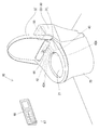
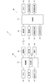
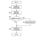
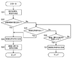
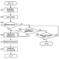
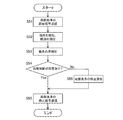
実施例1に係るトイレ装置が設けられたトイレルームの様子を示す説明図である。It is explanatory drawing which shows the mode of the toilet room in which the toilet apparatus which concerns on Example 1 was provided. 図1のリモートコントローラを概略的に示す斜視図である。It is a perspective view which shows the remote controller of FIG. 1 schematically. 図1のトイレ装置の電気的構成を概略的に例示するブロック図である。It is a block diagram which illustrates roughly the electric constitution of the toilet apparatus of FIG. 図1のリモートコントローラで実行される制御の流れを示すフローチャートである。It is a flowchart which shows the flow of control performed by the remote controller of FIG. 実施例2のリモートコントローラで実行される制御の流れを示すフローチャートである。FIG. 7 is a flowchart showing a flow of control executed by the remote controller according to the second embodiment. 実施例3のリモートコントローラで実行される制御の流れを示すフローチャートである。FIG. 16 is a flowchart showing the flow of control executed by the remote controller of the third embodiment. 実施例4のリモートコントローラで実行される制御の流れを示すフローチャートである。FIG. 16 is a flowchart showing the flow of control executed by the remote controller of the fourth embodiment. 実施例5のリモートコントローラで実行される制御の流れを示すフローチャートである。FIG. 16 is a flow chart showing the flow of control executed by the remote controller according to the fifth embodiment. 実施例6のリモートコントローラで実行される制御の流れを示すフローチャートである。FIG. 16 is a flowchart showing the flow of control executed by the remote controller according to the sixth embodiment.

本発明における好ましい実施の形態を説明する。   A preferred embodiment of the present invention will be described.

本発明のトイレ装置は、
便座への着座を検知する着座検知部を備え、
前記制御部は、前記センサによる処理結果に基づいて前記便鉢部に洗浄水を供給する便器洗浄の制御を行った後に、前記着座検知部によって前記便座からの離座が検知された場合に、前記便鉢部に洗浄水を供給する便器洗浄の制御を行わなくし得る。
この場合、このトイレ装置は、センサによる処理結果に基づいて便鉢部に洗浄水を供給する便器洗浄の制御が行われている場合、さらにセンサによる指先の検知結果に基づいて便器洗浄が行われることを防ぐことができる。このように、トイレ装置は、不要な便器洗浄が続けて行われることを防ぐことができる。
The toilet apparatus of the present invention is
It has a seating detection unit that detects seating on the toilet seat,
The control unit controls the toilet bowl to supply the washing water to the toilet based on the processing result by the sensor, and then, when the seating detection unit detects a release from the toilet seat, Control of the toilet bowl cleaning which supplies the flush water to the toilet bowl may be omitted.
In this case, the toilet apparatus performs toilet bowl cleaning based on the detection result of the fingertip by the sensor when control of toilet bowl cleaning is performed to supply flush water to the toilet based on the processing result by the sensor. You can prevent that. In this way, the toilet device can prevent unnecessary toilet flushing from continuing.

本発明のトイレ装置は、
前記センサによる処理結果に基づいて前記制御部によって実行される制御を設定する設定部を備え得る。
この場合、このトイレ装置は、センサによる処理結果に基づいて制御部によって実行される制御を、予め設定部によって設定することで、センサによる指先の検知結果に基づいて制御部が制御を行う際に、所望の制御を行うようにすることができる。
The toilet apparatus of the present invention is
The controller may include a setting unit configured to set the control to be executed by the control unit based on the processing result by the sensor.
In this case, the toilet apparatus sets the control to be executed by the control unit based on the processing result by the sensor in advance by the setting unit, and the control unit performs control based on the detection result of the fingertip by the sensor. The desired control can be performed.

次に、本発明のトイレ装置を具体化した実施例について、図面を参照しつつ説明する。   Next, an embodiment in which the toilet apparatus of the present invention is embodied will be described with reference to the drawings.

<実施例1>
実施例1のトイレ装置10は、図1に示すように、便器本体20、便座装置30、及びリモートコントローラ60を備えている。トイレ装置10は、リモートコントローラ60が操作されることによって、便座装置30の各種機能が発揮される。
Example 1
The toilet apparatus 10 according to the first embodiment, as shown in FIG. 1, includes a toilet body 20, a toilet seat apparatus 30, and a remote controller 60. The toilet device 10 exhibits various functions of the toilet seat device 30 when the remote controller 60 is operated.

便器本体20は、図1に示すように、トイレルームの床面上に設置される床置き式の水洗式便器である。便器本体20は、便鉢部21が形成されている。便鉢部21は、上端部が略楕円形状に開口した椀形状である。便鉢部21は、洗浄水が滞留する溜水部(図示略)が下部に形成されている。溜水部は、洗浄水が排出される排水路(図示略)が連通されている。   As shown in FIG. 1, the toilet body 20 is a floor-type flush toilet that is installed on the floor surface of the toilet room. A toilet bowl 21 is formed in the toilet bowl body 20. The toilet bowl 21 has a bowl shape whose upper end is opened in a substantially elliptical shape. The toilet bowl portion 21 is formed at its lower portion with a reservoir water portion (not shown) in which washing water is retained. The reservoir portion is in communication with a drainage passage (not shown) through which the washing water is discharged.

便座装置30は、図1に示すように、便器本体20の上面に組み付けられている。便座装置30は、便座31、便蓋32、及び本体33を有している。本体33は、便器本体20に着脱可能に固定されている。本体33は、後述する局部洗浄部42、温風乾燥部43、及び着座検知部44等の機能装置が組み付けられている。本体33は、上記機能装置の動作等を制御する機能部50を内部に収容する。機能部50は、後述する制御部51、及びメモリ52等を備えている。本体33は、便座31、及び便蓋32を、倒伏姿勢と起立姿勢との間で回動自在となるように軸支している。便座31は、内側が開口した環状に形成されている。便座31は、倒伏姿勢で便器本体20の便鉢部21の上端部に沿うように配置される。便蓋32は、倒伏姿勢において便座31を上方から覆い、便座31の開口及び便鉢部21の開口を塞ぐ。   The toilet seat device 30 is assembled on the upper surface of the toilet body 20, as shown in FIG. The toilet seat device 30 has a toilet seat 31, a toilet lid 32, and a main body 33. The main body 33 is detachably fixed to the toilet body 20. The main body 33 is assembled with functional devices such as a local cleaning unit 42, a warm air drying unit 43, and a seating detection unit 44 described later. The main body 33 accommodates therein a functional unit 50 that controls the operation and the like of the functional device. The function unit 50 includes a control unit 51 described later, a memory 52, and the like. The main body 33 pivotally supports the toilet seat 31 and the toilet lid 32 so as to be rotatable between the laid posture and the upright posture. The toilet seat 31 is formed in an annular shape with the inside open. The toilet seat 31 is disposed along the upper end portion of the toilet bowl 21 of the toilet body 20 in the laid posture. The toilet lid 32 covers the toilet seat 31 from above in the laid posture and closes the opening of the toilet seat 31 and the opening of the toilet bowl 21.

便座装置30は、図3に示すように、制御部51、メモリ52、通信部53、電源部54、便器洗浄部41、局部洗浄部42、温風乾燥部43、及び着座検知部44を備えている。制御部51は、公知のコンピュータとして構成され、便座装置30全体を制御する情報処理装置として機能する。制御部51は、メモリ52、通信部53、電源部54、便器洗浄部41、局部洗浄部42、温風乾燥部43、及び着座検知部44等が接続されている。制御部51は、局部洗浄部42、温風乾燥部43、及び着座検知部44等を動作させるための制御信号を出力する。メモリ52は、公知のメモリであり、局部洗浄部42等の各機能装置を制御可能なシステムプログラム等が予め格納されている。通信部53は、リモートコントローラ60と無線通信する。通信部53は、例えば赤外線通信を行う赤外線通信インタフェースとして構成されている。   As shown in FIG. 3, the toilet seat device 30 includes a control unit 51, a memory 52, a communication unit 53, a power supply unit 54, a toilet bowl cleaning unit 41, a local cleaning unit 42, a warm air drying unit 43, and a seating detection unit 44. ing. The control unit 51 is configured as a known computer, and functions as an information processing device that controls the entire toilet seat device 30. The control unit 51 is connected to a memory 52, a communication unit 53, a power supply unit 54, a toilet bowl cleaning unit 41, a local cleaning unit 42, a warm air drying unit 43, a seating detection unit 44, and the like. The control unit 51 outputs control signals for operating the local cleaning unit 42, the hot air drying unit 43, the seating detection unit 44, and the like. The memory 52 is a known memory, and stores in advance a system program that can control each functional device such as the local cleaning unit 42. The communication unit 53 wirelessly communicates with the remote controller 60. The communication unit 53 is configured, for example, as an infrared communication interface that performs infrared communication.

電源部54は、商用100V電源などの外部電源から電力供給を受けて、所定の電源電圧を生成するように機能する公知の電源回路などによって構成されている。電源部54は、出力する電源電圧が配線(図示略)を介して便器洗浄部41、局部洗浄部42、温風乾燥部43、及び着座検知部44等の様々な電子装置に供給される。   The power supply unit 54 is configured by a known power supply circuit or the like that receives power supply from an external power supply such as a commercial 100V power supply and generates a predetermined power supply voltage. The power supply unit 54 supplies a power supply voltage to be output to various electronic devices such as the toilet bowl cleaning unit 41, the local area cleaning unit 42, the hot air drying unit 43, and the seating detection unit 44 via wiring (not shown).

便器洗浄部41は、便鉢部21に洗浄水を供給する装置である。便器洗浄部41は、図示しない給水路、及び給水弁を備えている。給水路は、水道水等の洗浄水を便鉢部21に供給する通路である。給水路は、便鉢部21に通じている。給水弁は、例えば電磁弁として構成され、給水路の所定箇所に設けられている。便器洗浄部41は、制御部51からの便器洗浄の制御信号に基づいて、給水路を開放して便鉢部21への洗浄水の供給を開始し、所定時間の経過後に給水路を遮断して便鉢部21への洗浄水の供給を停止する。便器洗浄部41は、便鉢部21に洗浄水を供給し、便鉢部21内の便(大便、及び小便)を溜水部に滞留していた洗浄水とともに排水路へと排出する。   The toilet bowl cleaning unit 41 is a device for supplying cleaning water to the toilet bowl 21. The toilet bowl cleaning unit 41 includes a water supply passage (not shown) and a water supply valve. The water supply passage is a passage for supplying washing water such as tap water to the toilet bowl 21. The water supply passage leads to the toilet bowl 21. The water supply valve is configured, for example, as a solenoid valve, and is provided at a predetermined position of the water supply passage. The toilet bowl cleaning unit 41 opens the water supply channel based on the control signal for toilet bowl cleaning from the control unit 51 and starts supply of cleaning water to the toilet bowl 21 and shuts off the water channel after a predetermined time has elapsed. The supply of washing water to the toilet bowl 21 is stopped. The toilet bowl washing unit 41 supplies washing water to the toilet bowl 21 and discharges the stool (stool and urine) in the toilet bowl 21 to the drainage together with the washing water accumulated in the reservoir water.

局部洗浄部42は、リモートコントローラ60からの制御信号に基づいて局部を洗浄する。局部洗浄部42は、図1に示すように、洗浄水が吐出する洗浄ノズル42Aを備えている。局部洗浄部42は、本体33に形成された開口(図示略)を介して洗浄ノズル42Aが便鉢部21内に向けて進退可能になっている。洗浄ノズル42Aは、洗浄時に便鉢部21内に進出し、先端部から洗浄水が吐出することによって局部を洗浄する。   The local cleaning unit 42 cleans the local area based on the control signal from the remote controller 60. The local cleaning unit 42, as shown in FIG. 1, includes a cleaning nozzle 42A for discharging the cleaning water. The local cleaning unit 42 is capable of advancing and retracting the cleaning nozzle 42 </ b> A into the toilet bowl 21 through an opening (not shown) formed in the main body 33. The cleaning nozzle 42A advances into the toilet bowl 21 at the time of cleaning, and the local area is cleaned by discharging the cleaning water from the tip.

温風乾燥部43は、リモートコントローラ60からの制御信号に基づいて局部を温風によって乾燥させる。温風乾燥部43は、例えば、吸い込んだ外気をヒータで温めて、吹出口43Aから温風を前方に吹き出させる。   The warm air drying unit 43 dries the local area with warm air based on the control signal from the remote controller 60. For example, the warm air drying unit 43 warms the sucked outside air with a heater, and blows the warm air forward from the blowout port 43A.

着座検知部44は、使用者が便座31に着座した状態を検知する。着座検知部44は、図1に示すように、本体33に組み付けられている。着座検知部44は、公知の赤外線センサによって構成されている。着座検知部44は、図示しない発光素子(例えばLED等)、及び受光素子(例えばフォトダイオード等)を備えている。着座検知部44は、発光素子から赤外線が照射され、着座している使用者の人体で反射された赤外線を受光素子によって受光することにより、便座31上に使用者が着座していることを検知する。   The seating detection unit 44 detects a state in which the user is seated on the toilet seat 31. The seating detection unit 44 is assembled to the main body 33, as shown in FIG. The seating detection unit 44 is configured of a known infrared sensor. The seating detection unit 44 includes a light emitting element (for example, an LED or the like) and a light receiving element (for example, a photodiode or the like), which are not illustrated. The seating detection unit 44 detects that the user is seated on the toilet seat 31 by receiving infrared light emitted from the light emitting element and reflected from the human body of the seated user by the light receiving element. Do.

リモートコントローラ60は、便座装置30の各種機能を作動させるための入力装置である。リモートコントローラ60は、使用者の操作に応じた操作信号を無線信号によって便座装置30へ送信する。リモートコントローラ60は、図2に示すように、長手箱状に形成されている。リモートコントローラ60は、正面(壁面に対向する面とは反対の面)が操作面となっている。リモートコントローラ60は、例えば、背面(壁面に対向する面)に溝が形成され、壁面に固定されたホルダー部材70に形成されたレールに対して沿うようにスライドさせて差し込むことにより、リモートコントローラ60を壁面に着脱可能に取り付けられる。   The remote controller 60 is an input device for operating various functions of the toilet seat device 30. The remote controller 60 transmits an operation signal corresponding to the user's operation to the toilet seat device 30 by a wireless signal. The remote controller 60 is formed in a longitudinal box shape as shown in FIG. In the remote controller 60, the front surface (surface opposite to the surface facing the wall surface) is an operation surface. The remote controller 60 is, for example, formed by sliding along a rail formed in a holder member 70 fixed to the wall surface and having a groove formed on the back surface (surface facing the wall surface), thereby inserting the remote controller 60. Can be removably attached to the wall.

リモートコントローラ60は、図2に示すように、筐体60A、操作部63(操作ボタン63A、及び割当ボタン63B)、表示部65、及び脈波センサ(請求項の「センサ」に相当)67を備えている。筐体60Aは、内部にマイコンや電池66等が収容されている。操作部63は、例えばボタン式の入力スイッチとして構成されている。操作ボタン63Aは、便座装置30の動作、表示部65の表示の変更等を行うために操作される。操作ボタン63Aは、予め各種機能のいずれかが割り当てられている。例えば、複数の操作ボタン63Aは、それぞれ便蓋の開閉、便器洗浄、局部洗浄の開始、及び局部洗浄の停止等の制御を行うためのボタンである。   As shown in FIG. 2, the remote controller 60 includes a housing 60A, an operation unit 63 (operation button 63A and assignment button 63B), a display unit 65, and a pulse wave sensor (corresponding to “sensor” in the claims) 67. Have. The housing 60A accommodates a microcomputer, a battery 66, and the like inside. The operation unit 63 is configured as, for example, a button type input switch. The operation button 63A is operated to perform the operation of the toilet seat device 30, the display of the display unit 65, and the like. One of various functions is assigned to the operation button 63A in advance. For example, the plurality of operation buttons 63A are buttons for controlling the opening and closing of the toilet lid, the toilet bowl cleaning, the start of the local cleaning, the stop of the local cleaning, and the like.

表示部65は、液晶表示器や有機ELディスプレイなどの公知の表示装置によって構成されている。表示部65は、使用者の操作に応じた情報や、便座装置30の動作状態などの各種情報を表示する。   The display unit 65 is configured by a known display device such as a liquid crystal display or an organic EL display. The display unit 65 displays various information such as the information according to the user's operation and the operation state of the toilet seat device 30.

割当ボタン63Bは、リモートコントローラ60の操作内容や便座装置30の動作状態に応じて機能の割り当てが変わるボタンである。表示部65は、割当ボタン63Bに隣接する部分(上側で隣接する部分)に、その時点で割当ボタン63Bに割り当てられている機能を表示することで、ボタンと機能の対応を使用者が認識できる。リモートコントローラ60は、使用者が押下した割当ボタン63Bに対応する機能を、その時点での割り当てに基づいて特定し、後述する通信部64から赤外線通信で便座装置30に制御信号をさせたり、表示部65の表示を切り替えたりする。   The assignment button 63 </ b> B is a button in which assignment of functions changes in accordance with the operation content of the remote controller 60 and the operation state of the toilet seat device 30. The display unit 65 allows the user to recognize the correspondence between the button and the function by displaying the function assigned to the allocation button 63B at that time on the part adjacent to the allocation button 63B (the part adjacent on the upper side) . The remote controller 60 specifies a function corresponding to the allocation button 63B pressed by the user based on the allocation at that time, and causes the toilet seat device 30 to make a control signal by infrared communication from the communication unit 64 described later, or displays The display of the section 65 is switched.

脈波センサ67は、使用者の指先から脈波波形のデータを取得する装置である。脈波センサ67は、指置き部67A(図2参照)、発光素子(図示略)、及び受光素子(図示略)を備えている。指置き部67Aは、リモートコントローラ60の操作面上に配置されている。指置き部67Aは、透明な板状部材(例えば樹脂部材)によって構成されている。発光素子は、例えばLED等によって構成されている。受光素子は、例えばフォトダイオード等によって構成されている。脈波センサ67は、発光素子によって光を照射し、指置き部67A上に置かれた使用者の指先の血管で反射された光を受光素子で受光する。脈波センサ67は、指先の血管の拡張時と収縮時とで光の反射率が異なる現象を利用して、受光量の変動情報から血流の変化を使用者の脈波波形として検出する。   The pulse wave sensor 67 is a device that acquires pulse waveform data from the user's fingertip. The pulse wave sensor 67 includes a finger placement portion 67A (see FIG. 2), a light emitting element (not shown), and a light receiving element (not shown). The finger placement unit 67A is disposed on the operation surface of the remote controller 60. The finger placement portion 67A is configured of a transparent plate-like member (for example, a resin member). The light emitting element is configured of, for example, an LED or the like. The light receiving element is configured of, for example, a photodiode. The pulse wave sensor 67 emits light by the light emitting element, and the light receiving element receives the light reflected by the blood vessel of the user's fingertip placed on the finger placement portion 67A. The pulse wave sensor 67 detects a change in blood flow as a pulse wave waveform of the user from fluctuation information of the amount of received light, utilizing a phenomenon in which the reflectance of light differs between the time of expansion and contraction of the blood vessel of the fingertip.

リモートコントローラ60は、図3に示すように、制御部61、メモリ62、操作部63(操作ボタン63A、及び割当ボタン63B)、通信部64、表示部65、電池66、及び脈波センサ67を備えている。制御部61は、公知のコンピュータとして構成され、リモートコントローラ60全体を制御する情報処理装置として機能する。制御部61は、メモリ62、操作部63、通信部64、表示部65、電池66、及び脈波センサ67等が接続されている。制御部61は、表示部65、及び脈波センサ67等を動作させるための制御信号を出力する。メモリ62は、公知のメモリであり、脈波センサ67等の各機能装置を制御可能なシステムプログラム等が予め格納されている。操作部63は、使用者による操作に応じて、制御部61に対して操作信号を送信する。通信部64は、便座装置30と無線通信する。通信部64は、例えば赤外線通信を行う赤外線通信インタフェースとして構成されている。電池66は、所定の直流電圧を発生可能な乾電池等である。   As shown in FIG. 3, the remote controller 60 includes a control unit 61, a memory 62, an operation unit 63 (operation button 63A and assignment button 63B), a communication unit 64, a display unit 65, a battery 66, and a pulse wave sensor 67. Have. The control unit 61 is configured as a known computer and functions as an information processing apparatus that controls the entire remote controller 60. The control unit 61 is connected to a memory 62, an operation unit 63, a communication unit 64, a display unit 65, a battery 66, a pulse wave sensor 67, and the like. The control unit 61 outputs a control signal for operating the display unit 65, the pulse wave sensor 67, and the like. The memory 62 is a known memory, and stores in advance a system program that can control each functional device such as the pulse wave sensor 67. The operation unit 63 transmits an operation signal to the control unit 61 in accordance with an operation by the user. The communication unit 64 wirelessly communicates with the toilet seat device 30. The communication unit 64 is configured, for example, as an infrared communication interface that performs infrared communication. The battery 66 is a dry battery or the like capable of generating a predetermined DC voltage.

制御部61は、便座装置30に対して様々な制御を行わせるように制御信号を送信する。例えば、制御部61は、便座装置30に対して局部洗浄の開始信号及び停止信号を送信することで、それぞれ局部洗浄の開始制御及び停止制御を便座装置30に行わせる。制御部61は、便座装置30に対して温風乾燥の開始信号及び停止信号を送信することで、それぞれ温風乾燥の開始制御及び停止制御を便座装置30に行わせる。制御部61は、便座装置30に対して便器洗浄信号を送信することで、便座装置30に便器洗浄制御を行わせる。   The control unit 61 transmits a control signal to cause the toilet seat device 30 to perform various controls. For example, the control unit 61 transmits the local cleaning start signal and stop signal to the toilet seat device 30 to cause the toilet seat device 30 to perform local cleaning start control and stop control, respectively. The control unit 61 transmits the warm air drying start signal and stop signal to the toilet seat device 30 to cause the toilet seat device 30 to perform warm air drying start control and stop control, respectively. The control unit 61 transmits the toilet bowl cleaning signal to the toilet seat device 30 to cause the toilet seat device 30 to perform toilet bowl cleaning control.

制御部61は、脈波センサ67によって指先が検知されたか否か判定する機能を有する。具体的には、制御部61は、発光素子によって照射された光が指置き部67A上に置かれた使用者の指先の血管で反射されて受光素子で受光されて、脈波センサ67によって脈波測定が開始された場合に、指先が検知されたと判定する。   The control unit 61 has a function of determining whether or not a fingertip is detected by the pulse wave sensor 67. Specifically, the control unit 61 causes the light emitted from the light emitting element to be reflected by the blood vessel of the user's fingertip placed on the finger placement portion 67A and received by the light receiving element, and causes the pulse wave sensor 67 to When wave measurement is started, it is determined that a fingertip is detected.

制御部61は、脈波センサ67によって指先が検知された場合、または脈波センサ67によって指先が検知されなくなった場合に、便座装置30に関する様々な制御(自動制御)を行うように機能する。例えば、制御部61は、自動制御として、便座装置30に対して局部洗浄の開始信号及び停止信号を送信することで、それぞれ局部洗浄の開始制御及び停止制御を便座装置30に行わせる。制御部61は、自動制御として、便座装置30に対して温風乾燥の開始信号及び停止信号を送信することで、それぞれ温風乾燥の開始制御及び停止制御を便座装置30に行わせる。制御部61は、自動制御として、便座装置30に対して便器洗浄信号を送信することで、便座装置30に便器洗浄制御を行わせる。   The control unit 61 functions to perform various controls (automatic control) regarding the toilet seat device 30 when the finger is detected by the pulse wave sensor 67 or when the finger is not detected by the pulse wave sensor 67. For example, as an automatic control, the control unit 61 transmits a local cleaning start signal and a stop signal to the toilet seat device 30 to cause the toilet seat device 30 to perform local cleaning start control and stop control, respectively. The control unit 61 transmits the warm air drying start signal and stop signal to the toilet seat device 30 as automatic control, thereby causing the toilet seat device 30 to perform warm air drying start control and stop control. The control unit 61 causes the toilet seat device 30 to perform toilet bowl cleaning control by transmitting a toilet bowl cleaning signal to the toilet seat device 30 as automatic control.

制御部61は、図3に示すように、設定部61Aの機能が含まれている。制御部61で実行される設定部61Aの機能は、CPU等によるソフトウェア処理によって実現されてもよく、ハードウェア回路によって実現されてもよい。各機能は別々の装置によって実現されてもよく、共通の装置によって実現されてもよい。   As shown in FIG. 3, the control unit 61 includes the function of the setting unit 61A. The function of the setting unit 61A executed by the control unit 61 may be realized by software processing by a CPU or the like, or may be realized by a hardware circuit. Each function may be realized by separate devices or may be realized by a common device.

設定部61Aは、脈波センサ67によって指先が検知された場合に、制御部61によって実行される制御(自動制御)を設定する機能を有する部分である。設定部61Aは、メモリ62に自動制御の内容を記憶させることで、制御部61が自動制御に関する制御信号を便座装置30に送信する。例えば、リモートコントローラ60は、操作ボタン63A等を操作することで、表示部65によって1又は複数の自動制御の内容を割当ボタン63Bの操作で選択可能に表示させる。設定部61Aは、割当ボタン63Bの操作で選択した制御(自動制御)の内容をメモリ62に記憶させる。制御部61は、脈波センサ67によって指先が検知された場合に、メモリ62に記憶された選択内容に関する制御信号の送信を行う。   The setting unit 61A is a portion having a function of setting control (automatic control) to be executed by the control unit 61 when the finger is detected by the pulse wave sensor 67. The setting unit 61A causes the memory 62 to store the content of the automatic control, so that the control unit 61 transmits a control signal related to the automatic control to the toilet seat device 30. For example, by operating the operation button 63A or the like, the remote controller 60 causes the display unit 65 to display the contents of one or more automatic controls in a selectable manner by the operation of the assignment button 63B. The setting unit 61A stores the content of the control (automatic control) selected by the operation of the assignment button 63B in the memory 62. When the fingertip is detected by the pulse wave sensor 67, the control unit 61 transmits a control signal related to the selection content stored in the memory 62.

次に、リモートコントローラ60で実行される制御の流れについて、図4を参照して説明する。実施例1では、リモートコントローラ60は、脈波センサ67によって指先が検知された場合の自動制御の設定として局部洗浄の開始制御が、設定部61Aによってメモリ62に記憶されている。   Next, the flow of control executed by the remote controller 60 will be described with reference to FIG. In the first embodiment, as the setting of automatic control when the fingertip is detected by the pulse wave sensor 67, the remote controller 60 stores the start control of the local cleaning in the memory 62 by the setting unit 61A.

リモートコントローラ60は、脈波センサ67が起動状態にあり、指先が指置き部67Aに置かれて、脈波センサ67によって指先が検知されることで、図4の処理を開始する。ステップS11では、リモートコントローラ60は、脈波センサ67によって指先が検知されるとともに、脈波波形が測定される。リモートコントローラ60は、発光素子から光を照射するとともに受光素子で光が受光された場合に、発光素子から照射された光が指置き部67A上の指先で反射されて受光素子で受光されたとして、指置き部67Aに指先が置かれたと判定する。脈波センサ67は、受光素子で受光する受光量の時間変化を、脈波波形のデータとして測定する。   The remote controller 60 starts the process of FIG. 4 when the pulse wave sensor 67 is activated, the fingertip is placed on the finger placement portion 67A, and the finger is detected by the pulse wave sensor 67. In step S11, the remote controller 60 detects the fingertip by the pulse wave sensor 67 and measures the pulse waveform. In the case where the remote controller 60 emits light from the light emitting element and the light is received by the light receiving element, the light emitted from the light emitting element is reflected by the fingertip on the finger rest portion 67A and received by the light receiving element It is determined that the fingertip is placed on the finger placement portion 67A. The pulse wave sensor 67 measures the time change of the amount of light received by the light receiving element as data of the pulse waveform.

ステップS11の後、リモートコントローラ60は、メモリ62に自動制御の設定があるか否か判定する(ステップS12)。具体的には、リモートコントローラ60は、制御部61によって指先が検知された場合の自動制御に関する内容がメモリ62に記憶されているか否か判定する。図4に示す処理を実行する前に、予め設定部61Aによってメモリ62に自動制御の内容が記憶されている場合、Yesに進み、ステップS13の処理を行う。一方で、図4に示す処理を実行する前に、予め設定部61Aによってメモリ62に自動制御の内容が記憶されていない場合、Noに進み、ステップS14の処理を行う。   After step S11, the remote controller 60 determines whether or not there is an automatic control setting in the memory 62 (step S12). Specifically, the remote controller 60 determines whether or not the content related to automatic control when the control unit 61 detects a fingertip is stored in the memory 62. If the content of the automatic control is stored in advance in the memory 62 by the setting unit 61A before the process shown in FIG. 4 is performed, the process proceeds to Yes and the process of step S13 is performed. On the other hand, when the content of automatic control is not stored in advance in the memory 62 by the setting unit 61A before executing the process shown in FIG. 4, the process proceeds to No and performs the process of step S14.

ステップS14では、リモートコントローラ60は、局部洗浄の開始操作が行われたか否か判定する。具体的には、リモートコントローラ60は、使用者によって局部洗浄開始に関する操作ボタン63Aが押下されたか否か判定する。リモートコントローラ60は、局部洗浄の開始操作が行われたと判定する場合、Yesに進み、ステップS13の処理を行う。一方で、リモートコントローラ60は、局部洗浄の開始操作が行われていないと判定する場合、Noに進み、便座装置30から離座に関する信号を受信したか否か判定する(ステップS15)。便座装置30は、使用者が便座31から離座した場合に、着座検知部44によって使用者が便座31から離座した状態を検知する。便座装置30は、リモートコントローラ60に対して離座に関する信号を送信する。リモートコントローラ60は、離座に関する信号を受信したと判定する場合、Yesに進み、図4に示す処理を終了する。一方で、リモートコントローラ60は、離座に関する信号を受信していないと判定する場合、Noに進み、再びステップS14の処理を行う。   In step S14, the remote controller 60 determines whether the local cleaning start operation has been performed. Specifically, the remote controller 60 determines whether the user has pressed the operation button 63A related to the start of the local cleaning. If it is determined that the local washing start operation has been performed, the remote controller 60 proceeds to Yes, and performs the process of step S13. On the other hand, if the remote controller 60 determines that the local washing start operation has not been performed, the process proceeds to No and determines whether or not a signal relating to leaving is received from the toilet seat device 30 (step S15). When the user leaves the toilet seat 31, the toilet seat device 30 detects a state in which the user leaves the toilet seat 31 by the seating detection unit 44. The toilet seat device 30 transmits a signal regarding the remote seat to the remote controller 60. If the remote controller 60 determines that the signal relating to the departure has been received, the process proceeds to Yes, and the process illustrated in FIG. 4 ends. On the other hand, when it is determined that the remote controller 60 has not received the signal regarding the departure, the process proceeds to No and performs the process of step S14 again.

ステップS13では、リモートコントローラ60は、局部洗浄を指示する局部洗浄の開始信号を便座装置30に送信する。便座装置30は、局部洗浄の開始信号を受信して、局部洗浄処理を開始する。具体的には、便座装置30は、洗浄ノズル42Aを便鉢部21内に進出させ、先端部から洗浄水が吐出することによって局部を洗浄する。   In step S13, the remote controller 60 transmits to the toilet seat device 30 a start signal of the local cleaning, which instructs the local cleaning. The toilet seat device 30 receives the start signal of the local cleaning and starts the local cleaning process. Specifically, the toilet seat device 30 advances the cleaning nozzle 42A into the toilet bowl 21 and cleans the local area by discharging the cleaning water from the tip.

ステップS13に続いて、リモートコントローラ60は、局部洗浄の停止操作がなされる(ステップS16)。具体的には、リモートコントローラ60は、使用者によって局部洗浄停止に関する操作ボタン63Aが押下される。ステップS16に続いて、リモートコントローラ60は、局部洗浄を停止させる局部洗浄の停止信号を便座装置30に送信する(ステップS17)。便座装置30は、局部洗浄の停止信号を受信して、局部洗浄処理を停止する。ステップS17の処理の後、リモートコントローラ60は、図4に示す処理を終了する。   Following step S13, the remote controller 60 is operated to stop the local cleaning (step S16). Specifically, in the remote controller 60, the user presses the operation button 63A related to the local cleaning stop. Following step S16, the remote controller 60 transmits a stop signal of the local cleaning to stop the local cleaning to the toilet seat device 30 (step S17). The toilet seat device 30 receives the local cleaning stop signal to stop the local cleaning process. After the process of step S17, the remote controller 60 ends the process shown in FIG.

以下、本構成の効果を例示する。
実施例1のトイレ装置10は、脈波センサ67によって測定対象である指先を検知することができる。そして、制御部61は、脈波センサ67によって指先が検知された場合に、洗浄ノズル42Aから洗浄水を吐出する局部洗浄の開始制御を行う。このように、トイレ装置10は、脈波センサ67によって指先が検知されるタイミングで、局部洗浄の開始制御を実行することができる。そのため、トイレ装置10は、脈波センサ67によって指先が検知された後に、別途操作を行うことなく局部洗浄の開始制御を実行することができる。これにより、脈波センサ67によって脈波波形を測定するために指置き部67Aに指先を置いた後に、局部洗浄開始に関する操作ボタン63Aを押下する必要がなくなり、リモートコントローラ60の操作回数を低減させることができる。特に、指置き部67Aに指先を置いている状態で、さらに操作ボタン63Aを押下するという難しい操作を行うことを防ぐことができる。したがって、トイレ装置10は、操作性を向上させることができる。
Hereinafter, the effects of the present configuration will be illustrated.
The toilet apparatus 10 according to the first embodiment can detect a fingertip as an object to be measured by the pulse wave sensor 67. Then, when the finger is detected by the pulse wave sensor 67, the control unit 61 performs start control of the local cleaning for discharging the cleaning water from the cleaning nozzle 42A. Thus, the toilet apparatus 10 can execute the start control of the local washing at the timing when the fingertip is detected by the pulse wave sensor 67. Therefore, after the fingertip is detected by the pulse wave sensor 67, the toilet apparatus 10 can execute the start control of the local cleaning without performing a separate operation. As a result, after placing a fingertip on the finger placement portion 67A to measure a pulse waveform by the pulse wave sensor 67, there is no need to press the operation button 63A for the start of local cleaning, and the number of operations of the remote controller 60 is reduced. be able to. In particular, in the state where the fingertip is placed on the finger placement portion 67A, it is possible to prevent performing the difficult operation of pressing the operation button 63A. Therefore, the toilet apparatus 10 can improve operability.

トイレ装置10は、脈波センサ67による指先の検知結果(請求項の「処理結果」に相当)に基づいて制御部61によって実行される制御を設定する設定部61Aを備える。このため、トイレ装置10は、脈波センサ67による指先の検知結果に基づいて制御部61によって実行される制御を、予め設定部61Aによって設定することで、脈波センサ67による指先の検知結果に基づいて制御部61が制御を行う際に、所望の制御を行うようにすることができる。   The toilet apparatus 10 includes a setting unit 61A that sets control to be executed by the control unit 61 based on the result of detection of a fingertip by the pulse wave sensor 67 (corresponding to "processing result" in the claims). Therefore, the toilet apparatus 10 sets the control to be executed by the control unit 61 in advance by the setting unit 61A based on the detection result of the finger by the pulse wave sensor 67, thereby detecting the detection result of the finger by the pulse wave sensor 67. When the control unit 61 performs control based on it, desired control can be performed.

<実施例2>
次に、実施例2について説明する。
実施例2のトイレ装置10は、自動制御として、脈波センサ67で指先を検知した場合に、局部洗浄の停止制御を行う点が実施例1と異なる。その他の構成は実施例1と同一であり、同一の構成は同一の符号を付し、詳細な説明を省略する。
Example 2
Next, Example 2 will be described.
The toilet apparatus 10 of the second embodiment is different from the first embodiment in that stop control of the local cleaning is performed when the fingertip is detected by the pulse wave sensor 67 as the automatic control. The other configuration is the same as that of the first embodiment, and the same configuration is denoted by the same reference numeral and the detailed description is omitted.

リモートコントローラ60で実行される制御の流れについて、図5等を参照して説明する。実施例2のリモートコントローラ60は、脈波センサ67によって指先が検知された場合の自動制御の設定として局部洗浄の停止制御が、予め設定部61Aによってメモリ62に記憶されている。   The flow of control executed by the remote controller 60 will be described with reference to FIG. In the remote controller 60 according to the second embodiment, as setting of automatic control when the finger is detected by the pulse wave sensor 67, stop control of local washing is stored in advance in the memory 62 by the setting unit 61A.

リモートコントローラ60は、局部洗浄を指示する局部洗浄の開始信号を便座装置30に送信することで(ステップS21)、図5の処理を開始する。便座装置30は、局部洗浄の開始信号を受信して、局部洗浄処理を開始する。ステップS21に続いて、リモートコントローラ60は、使用者が指置き部67Aに指先を置くことで、実施例1(ステップS11)と同様に、脈波センサ67によって指先が検知されるとともに、脈波波形が測定される(ステップS22)。   The remote controller 60 starts the process of FIG. 5 by transmitting a start signal of the local cleaning to instruct the local cleaning to the toilet seat device 30 (step S21). The toilet seat device 30 receives the start signal of the local cleaning and starts the local cleaning process. After the step S21, the user places the fingertip on the finger placement portion 67A, so that the fingertip is detected by the pulse wave sensor 67 as in the first embodiment (step S11) and the pulse wave is detected. The waveform is measured (step S22).

ステップS22に続いて、リモートコントローラ60は、メモリ62に自動制御の設定があるか否か判定する(ステップS23)。具体的には、リモートコントローラ60は、制御部61によって指先が検知された場合の自動制御に関する内容がメモリ62に記憶されているか否か判定する。図5に示す処理を実行する前に、予め設定部61Aによってメモリ62に自動制御の内容が記憶されている場合、Yesに進み、ステップS24の処理を行う。   Subsequent to step S22, the remote controller 60 determines whether or not there is an automatic control setting in the memory 62 (step S23). Specifically, the remote controller 60 determines whether or not the content related to automatic control when the control unit 61 detects a fingertip is stored in the memory 62. If the content of the automatic control is stored in advance in the memory 62 by the setting unit 61A before the process shown in FIG. 5 is performed, the process proceeds to step S24.

ステップS24では、リモートコントローラ60は、局部洗浄を停止させる局部洗浄の停止信号を便座装置30に送信する。便座装置30は、局部洗浄の停止信号を受信して、局部洗浄処理を停止する。ステップS24の処理の後、リモートコントローラ60は、図5に示す処理を終了する。   In step S24, the remote controller 60 transmits to the toilet seat device 30 a stop signal of the local cleaning to stop the local cleaning. The toilet seat device 30 receives the local cleaning stop signal to stop the local cleaning process. After the process of step S24, the remote controller 60 ends the process shown in FIG.

ステップS23で、図5に示す処理を実行する前に、予め設定部61Aによってメモリ62に自動制御の内容が記憶されていない場合、Noに進み、ステップS25の処理を行う。ステップS25では、リモートコントローラ60は、局部洗浄の停止操作がなされる。具体的には、リモートコントローラ60は、使用者によって局部洗浄停止に関する操作ボタン63Aが押下される。ステップS25に続いて、リモートコントローラ60は、ステップS24の処理を行う。   In step S23, if the content of automatic control is not stored in the memory 62 in advance by the setting unit 61A before the process shown in FIG. 5 is performed, the process proceeds to No and the process of step S25 is performed. In step S25, the remote controller 60 is operated to stop the local cleaning. Specifically, in the remote controller 60, the user presses the operation button 63A related to the local cleaning stop. Following step S25, the remote controller 60 performs the process of step S24.

以上のように、実施例2のトイレ装置10では、制御部61は、脈波センサ67によって指先が検知された場合に、局部洗浄の停止制御を行う。このように、トイレ装置10は、脈波センサ67によって指先が検知されるタイミングで、局部洗浄の停止制御を実行することができる。そのため、トイレ装置10は、脈波センサ67によって指先が検知された後に、別途操作を行うことなく局部洗浄の停止制御を実行することができる。したがって、トイレ装置10は、操作回数を低減し、容易な操作が可能となり、操作性を向上させることができる。   As described above, in the toilet apparatus 10 of the second embodiment, when the pulse wave sensor 67 detects a fingertip, the control unit 61 performs stop control of the local cleaning. Thus, the toilet apparatus 10 can execute stop control of the local washing at the timing when the fingertip is detected by the pulse wave sensor 67. Therefore, after the fingertip is detected by the pulse wave sensor 67, the toilet apparatus 10 can execute stop control of the local cleaning without performing a separate operation. Therefore, the toilet apparatus 10 can reduce the number of operations, enable easy operation, and improve operability.

<実施例3>
次に、実施例3について説明する。
実施例3のトイレ装置10は、自動制御として、脈波センサ67で指先を検知した場合に、便器洗浄の制御を行う点が実施例1と異なる。その他の構成は実施例1と同一であり、同一の構成は同一の符号を付し、詳細な説明を省略する。
Example 3
Next, Example 3 will be described.
The toilet apparatus 10 according to the third embodiment is different from the first embodiment in that toilet control is controlled when the finger is detected by the pulse wave sensor 67 as the automatic control. The other configuration is the same as that of the first embodiment, and the same configuration is denoted by the same reference numeral and the detailed description is omitted.

リモートコントローラ60で実行される制御の流れについて、図6等を参照して説明する。実施例3のリモートコントローラ60は、脈波センサ67によって指先が検知された場合の自動制御の設定として便器洗浄の制御が、予め設定部61Aによってメモリ62に記憶されている。   The flow of control executed by the remote controller 60 will be described with reference to FIG. In the remote controller 60 according to the third embodiment, control of toilet bowl cleaning is stored in the memory 62 by the setting unit 61A in advance as setting of automatic control when the finger is detected by the pulse wave sensor 67.

リモートコントローラ60は、脈波センサ67が起動状態にあり、指先が指置き部67Aに置かれて、脈波センサ67によって指先が検知されることで、図6の処理を開始する。ステップS31では、リモートコントローラ60は、実施例1(ステップS11)と同様に、脈波センサ67によって指先が検知されるとともに、脈波波形が測定される。   The remote controller 60 starts the processing of FIG. 6 when the pulse wave sensor 67 is activated, the fingertip is placed on the finger placement portion 67A, and the fingertip is detected by the pulse wave sensor 67. In step S31, as with the first embodiment (step S11), in the remote controller 60, the finger is detected by the pulse wave sensor 67, and the pulse waveform is measured.

ステップS31の後、リモートコントローラ60は、メモリ62に自動制御の設定があるか否か判定する(ステップS32)。具体的には、リモートコントローラ60は、制御部61によって指先が検知された場合の自動制御に関する内容がメモリ62に記憶されているか否か判定する。図6に示す処理を実行する前に、予め設定部61Aによってメモリ62に自動制御の内容が記憶されている場合、Yesに進み、ステップS33の処理を行う。   After step S31, the remote controller 60 determines whether or not there is an automatic control setting in the memory 62 (step S32). Specifically, the remote controller 60 determines whether or not the content related to automatic control when the control unit 61 detects a fingertip is stored in the memory 62. If the content of the automatic control is stored in advance in the memory 62 by the setting unit 61A before the process shown in FIG. 6 is performed, the process proceeds to Yes and the process of step S33 is performed.

ステップS33では、リモートコントローラ60は、便器洗浄を指示する便器洗浄の制御信号を便座装置30に送信する。便座装置30は、便器洗浄の制御信号を受信して、便器洗浄処理を開始する。便座装置30は、便器洗浄の制御信号を受信して、便器洗浄処理を行う。具体的には、便座装置30は、便器洗浄部41によって、給水路を開放して便鉢部21への洗浄水の供給を開始し、所定時間の経過後に給水路を遮断して便鉢部21への洗浄水の供給を停止する。   In step S33, the remote controller 60 transmits to the toilet seat device 30 a toilet bowl cleaning control signal instructing the toilet bowl cleaning. The toilet seat device 30 receives the control signal of toilet bowl cleaning and starts the toilet bowl cleaning process. The toilet seat device 30 receives the control signal of toilet bowl cleaning and performs the toilet bowl cleaning process. Specifically, the toilet seat device 30 opens the water supply channel by the toilet bowl cleaning unit 41 and starts supply of flush water to the toilet bowl 21 and shuts off the water supply channel after a predetermined time has elapsed, thereby the toilet bowl component Stop the supply of washing water to 21.

ステップS33に続いて、リモートコントローラ60は、便座装置30は、便座装置30から離座に関する信号を受信し(ステップS34)、便器洗浄の制御信号を送信することなく、図6の処理を終了する。便座装置30は、使用者が便座31から離座した場合に、着座検知部44によって使用者が便座31から離座した状態を検知する。便座装置30は、リモートコントローラ60に対して離座に関する信号を送信する。   Subsequent to step S33, the remote control 60 receives the signal relating to the seat release from the toilet seat device 30 from the toilet seat device 30 (step S34), and ends the process of FIG. 6 without transmitting the toilet bowl cleaning control signal. . When the user leaves the toilet seat 31, the toilet seat device 30 detects a state in which the user leaves the toilet seat 31 by the seating detection unit 44. The toilet seat device 30 transmits a signal regarding the remote seat to the remote controller 60.

ステップS32で、図6に示す処理を実行する前に、予め設定部61Aによってメモリ62に自動制御の内容が記憶されていない場合、Noに進み、ステップS35の処理を行う。ステップS35では、リモートコントローラ60は、便器洗浄の操作が行われたか否か判定する。具体的には、リモートコントローラ60は、使用者によって便器洗浄に関する操作ボタン63Aが押下されたか否か判定する。リモートコントローラ60は、便器洗浄の操作が行われたと判定する場合、Yesに進み、ステップS33の処理を行う。   If the content of the automatic control is not stored in advance in the memory 62 by the setting unit 61A before the process shown in FIG. 6 is performed in step S32, the process proceeds to No and the process of step S35 is performed. In step S35, the remote controller 60 determines whether or not the toilet flushing operation has been performed. Specifically, the remote controller 60 determines whether or not the user has pressed the operation button 63A related to toilet bowl cleaning. If it is determined that the toilet flushing operation has been performed, the remote controller 60 proceeds to Yes and performs the process of step S33.

一方で、リモートコントローラ60は、ステップS35で、便器洗浄の操作が行われていないと判定する場合、Noに進み、便座装置30から離座に関する信号を受信したか否か判定する(ステップS36)。リモートコントローラ60は、離座に関する信号を受信したと判定する場合、Yesに進み、便器洗浄を指示する便器洗浄の制御信号を便座装置30に送信する(ステップS37)。リモートコントローラ60は、ステップS37の処理を実行すると、図6に示す処理を終了する。   On the other hand, if the remote controller 60 determines in step S35 that the toilet flushing operation has not been performed, the process proceeds to No and determines whether or not the signal relating to the release has been received from the toilet seat device 30 (step S36). . If the remote controller 60 determines that it has received a signal relating to leaving the seat, the process proceeds to Yes, and transmits a toilet bowl cleaning control signal instructing the toilet bowl cleaning to the toilet seat device 30 (step S37). After executing the process of step S37, the remote controller 60 ends the process shown in FIG.

以上のように、実施例3のトイレ装置10では、制御部61は、脈波センサ67によって指先が検知された場合に、便器洗浄の制御を行う。このように、トイレ装置10は、脈波センサ67によって指先が検知されるタイミングで、便器洗浄の制御を実行することができる。そのため、トイレ装置10は、脈波センサ67によって指先が検知された後に、別途操作を行うことなく便器洗浄の制御を実行することができる。したがって、トイレ装置10は、操作回数を低減し、容易な操作が可能となり、操作性を向上させることができる。   As described above, in the toilet apparatus 10 of the third embodiment, the control unit 61 controls the toilet bowl cleaning when the pulse wave sensor 67 detects a fingertip. Thus, the toilet apparatus 10 can execute toilet bowl cleaning control at the timing when the fingertip is detected by the pulse wave sensor 67. Therefore, after the fingertip is detected by the pulse wave sensor 67, the toilet apparatus 10 can execute control of toilet bowl cleaning without performing a separate operation. Therefore, the toilet apparatus 10 can reduce the number of operations, enable easy operation, and improve operability.

実施例3のトイレ装置10は、制御部61が、脈波センサ67による指先の検知結果(請求項の「処理結果」に相当)に基づいて便器洗浄の制御を行った後に(ステップS33)、着座検知部44によって便座31からの離座が検知された場合に、便鉢部21に洗浄水を供給する便器洗浄の制御を行わない。このため、トイレ装置10は、脈波センサ67による指先の検知結果に基づいて便鉢部21に洗浄水を供給する便器洗浄の制御が行われている場合、さらに脈波センサ67による指先の検知結果に基づいて便器洗浄が行われることを防ぐことができる。このように、トイレ装置10は、不要な便器洗浄が続けて行われることを防ぐことができる。   In the toilet apparatus 10 according to the third embodiment, after the control unit 61 controls the toilet flushing based on the detection result of the fingertip by the pulse wave sensor 67 (corresponding to “processing result” in the claims) (step S33), When the seating detection unit 44 detects the release from the toilet seat 31, the control of the toilet flushing for supplying the washing water to the toilet bowl 21 is not performed. Therefore, the toilet apparatus 10 further detects the fingertip by the pulse wave sensor 67 when the toilet bowl cleaning control is performed to supply flush water to the toilet 21 based on the detection result of the finger by the pulse wave sensor 67. It can prevent that toilet bowl cleaning is performed based on a result. Thus, the toilet apparatus 10 can prevent unnecessary toilet cleaning from being performed continuously.

<実施例4>
次に、実施例4について説明する。
実施例4のトイレ装置10は、自動制御として、脈波センサ67で指先を検知しなくなった場合に、便座装置30に関する様々な制御(自動制御)を行う点が実施例1と異なる。その他の構成は実施例1と同一であり、同一の構成は同一の符号を付し、詳細な説明を省略する。
Example 4
Next, the fourth embodiment will be described.
The toilet apparatus 10 of the fourth embodiment is different from the first embodiment in that various controls (automatic control) regarding the toilet seat device 30 are performed as the automatic control when the pulse wave sensor 67 no longer detects a fingertip. The other configuration is the same as that of the first embodiment, and the same configuration is denoted by the same reference numeral and the detailed description is omitted.

制御部61は、脈波センサ67によって指先が検知されなくなった場合に、便座装置30に関する様々な制御(自動制御)を行うように機能する。具体的には、制御部61は、実施例1と同様に、便座装置30に対して、洗浄ノズル42Aから洗浄水を吐出する局部洗浄の開始制御もしくは停止制御、吹出口43Aから温風を吹き出して局部を乾燥させる温風乾燥の開始制御もしくは停止制御、又は、便器本体の便鉢部に洗浄水を供給する便器洗浄の制御などを行う。   The control unit 61 functions to perform various controls (automatic control) regarding the toilet seat device 30 when the finger is not detected by the pulse wave sensor 67. Specifically, as in the first embodiment, the control unit 61 performs start control or stop control of local cleaning for discharging the cleaning water from the cleaning nozzle 42A to the toilet seat device 30, and blows warm air from the outlet 43A. Start control or stop control of warm air drying to dry the local part, or control of toilet bowl cleaning which supplies washing water to the toilet bowl of the toilet bowl main body is performed.

設定部61Aは、脈波センサ67によって指先が検知されなくなった場合に、制御部61によって実行される制御(自動制御)を設定する機能を有する部分である。設定部61Aは、実施例1と同様に、メモリ62に自動制御の内容を記憶させることで、制御部61が自動制御に関する制御信号を便座装置30に送信する。   The setting unit 61A is a part having a function of setting control (automatic control) to be executed by the control unit 61 when the finger is not detected by the pulse wave sensor 67. As in the first embodiment, the setting unit 61A stores the contents of the automatic control in the memory 62, so that the control unit 61 transmits a control signal related to the automatic control to the toilet seat device 30.

リモートコントローラ60で実行される制御の流れについて、図7等を参照して説明する。実施例4のリモートコントローラ60は、脈波センサ67によって指先が検知されなくなった場合の自動制御の設定として局部洗浄の開始制御が、予め設定部61Aによってメモリ62に記憶されている。   The flow of control executed by the remote controller 60 will be described with reference to FIG. In the remote controller 60 of the fourth embodiment, as setting of automatic control when the finger is not detected by the pulse wave sensor 67, start control of local washing is stored in advance in the memory 62 by the setting unit 61A.

リモートコントローラ60は、脈波センサ67が起動状態にあり、指先が指置き部67Aに置かれて、脈波センサ67によって指先が検知されることで、図7の処理を開始する。ステップS41では、リモートコントローラ60は、実施例1(ステップS11)と同様に、脈波センサ67によって指先が検知されるとともに、脈波波形が測定される。   The remote controller 60 starts the processing of FIG. 7 when the pulse wave sensor 67 is activated, the fingertip is placed on the finger placement portion 67A, and the fingertip is detected by the pulse wave sensor 67. In step S41, as with the first embodiment (step S11), the remote controller 60 detects the fingertip by the pulse wave sensor 67 and measures the pulse waveform.

リモートコントローラ60は、ステップS41の後、脈波センサ67によって指先が検知されなくなったことを検出する(ステップS42)。リモートコントローラ60は、受光素子で受光されていた指置き部67A上の指先で反射された光が検出しなくなった場合に、指置き部67A上から指先が離れたとして、指先が検知されなくなったことを検出する。   After step S41, the remote controller 60 detects that the fingertip is not detected by the pulse wave sensor 67 (step S42). When the light reflected by the finger on the finger placement portion 67A received by the light receiving element is not detected, the remote controller 60 detects that the fingertip is not detected from the finger placement portion 67A. To detect that.

リモートコントローラ60は、ステップS42の後、メモリ62に自動制御の設定があるか否か判定する(ステップS43)。具体的には、リモートコントローラ60は、制御部61によって指先が検知されなくなった場合の自動制御に関する内容がメモリ62に記憶されているか否か判定する。リモートコントローラ60は、メモリ62に自動制御の設定があると判定する場合、Yesに進み、ステップS44の処理を行う。一方で、リモートコントローラ60は、メモリ62に自動制御の設定がないと判定する場合、Noに進み、ステップS45の処理を行う。以降、ステップS44〜S48の処理は、実施例1のステップS13〜S17の処理と同様であり、説明を省略する。   After step S42, the remote controller 60 determines whether or not the memory 62 is set for automatic control (step S43). Specifically, the remote controller 60 determines whether or not the content related to the automatic control is stored in the memory 62 when the fingertip is not detected by the control unit 61. If the remote controller 60 determines that the setting of the automatic control is in the memory 62, the process proceeds to step S44. On the other hand, when it is determined that the setting of the automatic control is not in the memory 62, the remote controller 60 proceeds to No and performs the process of step S45. The processes of steps S44 to S48 are the same as the processes of steps S13 to S17 of the first embodiment, and the description thereof will be omitted.

このトイレ装置10は、制御部61が、脈波センサ67によって指先が検知されなくなった場合に、局部洗浄の開始制御を行う。このように、トイレ装置10は、脈波センサ67によって指先が検知されなくなるタイミングで、局部洗浄の開始制御を実行することができる。そのため、トイレ装置10は、脈波センサ67によって測定された指先が脈波センサ67から離れたりして検知されなくなった後に、別途操作を行うことなく、局部洗浄の開始制御を実行することができる。これにより、脈波センサ67による脈波波形の測定が終了して、指置き部67Aから指先を離した後に、局部洗浄開始に関する操作ボタン63Aを押下する必要がなくなり、リモートコントローラ60の操作回数を低減させることができる。したがって、トイレ装置10は、操作性を向上させることができる。特に、トイレ装置は、脈波センサ67による指先の測定が終了して指先が脈波センサ67から離れてから局部洗浄の開始制御を実行することで、使用者が局部洗浄に気を取られることなく脈波センサ67による指先の測定に集中することができる。   In the toilet apparatus 10, the control unit 61 performs the start control of the local cleaning when the finger is not detected by the pulse wave sensor 67. Thus, the toilet apparatus 10 can execute the start control of the local washing at the timing when the fingertip is not detected by the pulse wave sensor 67. Therefore, after the fingertip measured by the pulse wave sensor 67 is separated from the pulse wave sensor 67 and stopped being detected, the toilet apparatus 10 can execute the start control of the local cleaning without performing a separate operation. . As a result, after the measurement of the pulse waveform by the pulse wave sensor 67 is completed and it is not necessary to press the operation button 63A related to the start of the local cleaning after releasing the fingertip from the finger placement portion 67A, the number of operations of the remote controller 60 is increased. It can be reduced. Therefore, the toilet apparatus 10 can improve operability. In particular, in the toilet apparatus, the user is distracted in the local cleaning by executing the start control of the local cleaning after the measurement of the fingertip by the pulse sensor 67 is finished and the fingertip is separated from the pulse sensor 67. It is possible to concentrate on the measurement of the fingertip by the pulse wave sensor 67.

<実施例5>
次に、実施例5について説明する。
実施例5のトイレ装置10は、自動制御として、脈波センサ67で指先を検知しなくなった場合に、局部洗浄の停止制御を行う点が実施例4と異なる。その他の構成は実施例4と同一であり、同一の構成は同一の符号を付し、詳細な説明を省略する。
Example 5
Example 5 will now be described.
The toilet apparatus 10 of the fifth embodiment is different from the fourth embodiment in that stop control of the local washing is performed when the pulse wave sensor 67 no longer detects a fingertip as automatic control. The other configuration is the same as that of the fourth embodiment, the same configuration is denoted by the same reference numeral, and the detailed description is omitted.

リモートコントローラ60で実行される制御の流れについて、図8等を参照して説明する。実施例5のリモートコントローラ60は、脈波センサ67によって指先が検知されなくなった場合の自動制御の設定として局部洗浄の停止制御が、予め設定部61Aによってメモリ62に記憶されている。   The flow of control executed by the remote controller 60 will be described with reference to FIG. In the remote controller 60 of the fifth embodiment, as setting of automatic control when the finger is not detected by the pulse wave sensor 67, stop control of local washing is stored in advance in the memory 62 by the setting unit 61A.

リモートコントローラ60は、局部洗浄を指示する局部洗浄の開始信号を便座装置30に送信することで(ステップS51)、図8の処理を開始する。便座装置30は、局部洗浄の開始信号を受信して、局部洗浄処理を開始する。ステップS51に続いて、リモートコントローラ60は、使用者が指置き部67Aに指先を置くことで、実施例1(ステップS11)と同様に、脈波センサ67によって指先が検知されるとともに、脈波波形が測定される(ステップS52)。   The remote controller 60 starts the process of FIG. 8 by transmitting the start signal of the local cleaning to instruct the local cleaning to the toilet seat device 30 (step S51). The toilet seat device 30 receives the start signal of the local cleaning and starts the local cleaning process. After the step S51, the user places the fingertip on the finger placement portion 67A, so that the fingertip is detected by the pulse wave sensor 67 as in the first embodiment (step S11), and the pulse wave is detected. The waveform is measured (step S52).

ステップS52に続いて、リモートコントローラ60は、実施例4(ステップS42)と同様に、脈波センサ67によって指先が検知されなくなったことを検出する(ステップS53)。   Subsequent to step S52, as in the fourth embodiment (step S42), the remote controller 60 detects that the finger is not detected by the pulse wave sensor 67 (step S53).

リモートコントローラ60は、ステップS53の後、メモリ62に自動制御の設定があるか否か判定する(ステップS54)。具体的には、リモートコントローラ60は、制御部61によって指先が検知されなくなった場合の自動制御に関する内容がメモリ62に記憶されているか否か判定する。リモートコントローラ60は、メモリ62に自動制御の設定があると判定する場合、Yesに進み、ステップS55の処理を行う。一方で、リモートコントローラ60は、メモリ62に自動制御の設定がないと判定する場合、Noに進み、ステップS56の処理を行う。以降、ステップS55、S56の処理は、実施例2のステップS24、S25の処理と同様であり、説明を省略する。   After step S53, the remote controller 60 determines whether or not the memory 62 is set for automatic control (step S54). Specifically, the remote controller 60 determines whether or not the content related to the automatic control is stored in the memory 62 when the fingertip is not detected by the control unit 61. If it is determined that the automatic control setting is in the memory 62, the remote controller 60 proceeds to Yes and performs the process of step S55. On the other hand, when it is determined that the setting of the automatic control is not in the memory 62, the remote controller 60 proceeds to No and performs the process of step S56. The processes of steps S55 and S56 are the same as the processes of steps S24 and S25 of the second embodiment, and the description thereof will be omitted.

以上のように、実施例5のトイレ装置10では、制御部61は、脈波センサ67によって指先が検知されなくなった場合に、局部洗浄の停止制御を行う。このように、トイレ装置10は、脈波センサ67によって指先が検知されなくなるタイミングで、局部洗浄の停止制御を実行することができる。そのため、トイレ装置10は、脈波センサ67によって指先が検知されなくなった後に、別途操作を行うことなく局部洗浄の停止制御を実行することができる。したがって、トイレ装置10は、操作回数を低減し、操作性を向上させることができる。   As described above, in the toilet apparatus 10 of the fifth embodiment, the control unit 61 performs stop control of the local cleaning when the finger is not detected by the pulse wave sensor 67. As described above, the toilet apparatus 10 can execute stop control of the local washing at timing when the fingertip is not detected by the pulse wave sensor 67. Therefore, after the fingertip is not detected by the pulse wave sensor 67, the toilet apparatus 10 can execute stop control of the local cleaning without performing a separate operation. Therefore, the toilet apparatus 10 can reduce the number of operations and improve the operability.

<実施例6>
次に、実施例6について説明する。
実施例6のトイレ装置10は、自動制御として、脈波センサ67で指先を検知しなくなった場合に、便器洗浄の制御を行う点が実施例4と異なる。その他の構成は実施例4と同一であり、同一の構成は同一の符号を付し、詳細な説明を省略する。
Example 6
A sixth embodiment will now be described.
The toilet apparatus 10 according to the sixth embodiment is different from the fourth embodiment in that toilet control of toilet bowl cleaning is performed when the pulse wave sensor 67 no longer detects a fingertip as automatic control. The other configuration is the same as that of the fourth embodiment, the same configuration is denoted by the same reference numeral, and the detailed description is omitted.

リモートコントローラ60で実行される制御の流れについて、図9等を参照して説明する。実施例6のリモートコントローラ60は、脈波センサ67によって指先が検知されなくなった場合の自動制御の設定として便器洗浄の制御が、予め設定部61Aによってメモリ62に記憶されている。   The flow of control executed by the remote controller 60 will be described with reference to FIG. In the remote controller 60 of the sixth embodiment, control of toilet bowl cleaning is stored in advance in the memory 62 by the setting unit 61A as setting of automatic control when the finger is not detected by the pulse wave sensor 67.

リモートコントローラ60は、脈波センサ67が起動状態にあり、指先が指置き部67Aに置かれて、脈波センサ67によって指先が検知されることで、図9の処理を開始する。ステップS61では、リモートコントローラ60は、実施例1(ステップS11)と同様に、脈波センサ67によって指先が検知されるとともに、脈波波形が測定される。   The pulse wave sensor 67 is activated, the fingertip is placed on the finger placement portion 67A, and the fingertip is detected by the pulse wave sensor 67, thereby starting the processing of FIG. In step S61, as with the first embodiment (step S11), the remote controller 60 detects the fingertip by the pulse wave sensor 67 and measures the pulse waveform.

リモートコントローラ60は、ステップS61の後、実施例4(ステップS42)と同様に、脈波センサ67によって指先が検知されなくなったことを検出する(ステップS62)。   After step S61, the remote controller 60 detects that the finger is not detected by the pulse wave sensor 67 (step S62) as in the fourth embodiment (step S42).

リモートコントローラ60は、ステップS62の後、メモリ62に自動制御の設定があるか否か判定する(ステップS63)。具体的には、リモートコントローラ60は、制御部61によって指先が検知されなくなった場合の自動制御に関する内容がメモリ62に記憶されているか否か判定する。リモートコントローラ60は、メモリ62に自動制御の設定があると判定する場合、Yesに進み、ステップS64の処理を行う。一方で、リモートコントローラ60は、メモリ62に自動制御の設定がないと判定する場合、Noに進み、ステップS66の処理を行う。以降、ステップS64〜S68の処理は、実施例3のステップS33〜S37の処理と同様であり、説明を省略する。   After step S62, the remote controller 60 determines whether or not the memory 62 is set for automatic control (step S63). Specifically, the remote controller 60 determines whether or not the content related to the automatic control is stored in the memory 62 when the fingertip is not detected by the control unit 61. If the remote controller 60 determines that the setting of the automatic control is in the memory 62, it proceeds to Yes and performs the process of step S64. On the other hand, when it is determined that the setting of the automatic control is not in the memory 62, the remote controller 60 proceeds to No and performs the process of step S66. The processes of steps S64 to S68 are the same as the processes of steps S33 to S37 of the third embodiment, and the description thereof will be omitted.

以上のように、実施例6のトイレ装置10では、制御部61は、脈波センサ67によって指先が検知されなくなった場合に、便器洗浄の制御を行う。このように、トイレ装置10は、脈波センサ67によって指先が検知されなくなるタイミングで、便器洗浄の制御を実行することができる。そのため、トイレ装置10は、脈波センサ67によって指先が検知されなくなった後に、別途操作を行うことなく便器洗浄の制御を実行することができる。したがって、トイレ装置10は、操作回数を低減し、操作性を向上させることができる。   As described above, in the toilet apparatus 10 of the sixth embodiment, the control unit 61 controls the toilet bowl cleaning when the finger is not detected by the pulse wave sensor 67. Thus, the toilet apparatus 10 can execute control of toilet bowl cleaning at timing when the fingertip is not detected by the pulse wave sensor 67. Therefore, after the fingertip is not detected by the pulse wave sensor 67, the toilet device 10 can execute control of toilet bowl cleaning without performing an additional operation. Therefore, the toilet apparatus 10 can reduce the number of operations and improve the operability.

実施例6のトイレ装置10は、制御部61が、脈波センサ67による指先の検知結果に基づいて便器洗浄の制御を行った後に(ステップS64)、着座検知部44によって便座31からの離座が検知された場合に、便鉢部21に洗浄水を供給する便器洗浄の制御を行わない。このように、トイレ装置10は、不要な便器洗浄が続けて行われることを防ぐことができる。   In the toilet apparatus 10 of the sixth embodiment, after the control unit 61 controls the toilet flushing based on the detection result of the finger by the pulse wave sensor 67 (step S64), the seating detection unit 44 removes the seat from the toilet seat 31 When is detected, the control of the toilet flush which supplies flush water to the toilet bowl 21 is not performed. Thus, the toilet apparatus 10 can prevent unnecessary toilet cleaning from being performed continuously.

本発明は上記記述及び図面によって説明した実施例に限定されるものではなく、例えば次のような実施例も本発明の技術的範囲に含まれる。
(1)実施例4〜6では、トイレ装置10は、脈波センサ67で指先を検知しなくなった場合に、便座装置30に関する様々な制御(自動制御)を行ったが、脈波センサ67による脈波測定が完了した場合に、自動制御を行ってもよい。
この場合、制御部61は、脈波センサ67による脈波測定が完了した場合(例えば、脈波センサ67による脈波測定が一定時間行われて測定が完了した場合)に、実施例4〜6と同様の自動制御を行うように機能する。設定部61Aは、実施例4〜6と同様に、メモリ62に自動制御の内容を記憶させることで、制御部61が自動制御に関する制御信号を便座装置30に送信する。
例えば、制御部61は、実施例4〜6のリモートコントローラ60による処理において、脈波センサ67による指先が検知されなくなったことの検出(図7のステップS42、図8のステップS53、図9のステップS62)の代わりに、脈波センサ67による脈波測定が完了したことの検出を行う構成とし得る。
(2)実施例1,4では、リモートコントローラ60が行う自動制御として、局部洗浄の開始制御を行う例を示したが、吹出口43Aから温風を吹き出して局部を乾燥させる温風乾燥の開始制御を行ってもよい。同様に、実施例2,5では、リモートコントローラ60が行う自動制御として、局部洗浄の停止制御を行う例を示したが、温風乾燥の停止制御を行ってもよい。これらの場合、リモートコントローラ60は、自動制御の設定として温風乾燥の開始制御が、予め設定部61Aによってメモリ62に記憶されている。
(3)実施例1〜6では、リモートコントローラ60は、自動制御として、局部洗浄の開始制御もしくは停止制御、温風乾燥の開始制御もしくは停止制御、又は、便器洗浄の制御のうちのいずれか1つの制御を行う例を示したが、これらの制御のうち複数の制御を行ってもよい。例えば、リモートコントローラ60は、自動制御の設定として、局部洗浄の開始制御および温風乾燥の開始制御が、予め設定部61Aによってメモリ62に記憶されている場合、自動制御が行われる際に、局部洗浄を開始させて、局部洗浄の停止後(所定時間の経過による自動停止後や停止操作後)に温風乾燥の開始制御が自動的に行われる。
(4)実施例1〜6では、リモートコントローラ60の制御部61が脈波センサ67の検知結果に基づいて自動制御を行う構成を示したが、便座装置30の制御部51が脈波センサ67の検知結果に基づいて自動制御を行う構成であってもよい。この場合、リモートコントローラ60は、脈波センサ67による指先の検知結果を便座装置30に送信する。便座装置30の制御部51は、図3に示す設定部61Aと同様の機能が含まれている。便座装置30は、受信した指先の検知結果に基づいて自動制御(局部洗浄の開始制御もしくは停止制御、又は便器洗浄の制御など)を行う。
(5)実施例1〜6では、リモートコントローラ60は、脈波センサ67によって指先が検知されるとともに、脈波波形を測定する例(例えば、ステップS11)を示したが、脈波センサ67によって指先が検知された後に、脈波波形を測定してもよい。例えば、リモートコントローラ60は、所定時間分の脈波波形のデータを測定した後や、脈波センサ67の他に別途設けた指先検知センサによって指先が検知された後に、脈波波形を測定してもよい。
(6)実施例1〜6では、脈波センサ67は、受光素子が指置き部67A上に置かれた使用者の指先の血管で反射された光を受光する構成であったが、指先の血管を透過した光を受光する構成(透過型の脈波センサ)であってもよい。
(7)実施例1〜6では、センサの一例として脈波センサ67を示したが、センサは、指先を測定対象とした測定を行うセンサであれば、血圧計等であってもよい。
(8)実施例1〜6では、便座装置30とリモートコントローラ60は、赤外線通信によって信号を送受する構成であったが、Bluetooth(登録商標)等の電波を用いた無線通信方式によって信号を送受してもよい。
(9)実施例1〜6では、着座検知部44は、公知の赤外線センサによって構成されていたが、静電容量式や体重検知式のセンサであってもよい。
(10)実施例1〜6では、便器本体20は、トイレルームの床面上に設置される床置き式である例を示したが、壁掛け式であってもよい。
The present invention is not limited to the embodiments described above with reference to the drawings. For example, the following embodiments are also included in the technical scope of the present invention.
(1) In the fourth to sixth embodiments, the toilet apparatus 10 performs various controls (automatic control) on the toilet seat apparatus 30 when the pulse wave sensor 67 no longer detects a fingertip, but the pulse wave sensor 67 Automatic control may be performed when pulse wave measurement is completed.
In this case, when the pulse wave measurement by the pulse wave sensor 67 is completed (for example, when the pulse wave measurement by the pulse wave sensor 67 is performed for a certain period of time and the measurement is completed), the control unit 61 Function to perform the same automatic control as. As in the fourth to sixth embodiments, the setting unit 61A causes the memory 62 to store the contents of automatic control, so that the control unit 61 transmits a control signal related to automatic control to the toilet seat device 30.
For example, in the processing by the remote controller 60 according to the fourth to sixth embodiments, the control unit 61 detects that the finger is not detected by the pulse wave sensor 67 (step S42 in FIG. 7, step S53 in FIG. 8, and FIG. Instead of step S62), it may be configured to detect that the pulse wave measurement by the pulse wave sensor 67 is completed.
(2) In the first and fourth embodiments, as the automatic control performed by the remote controller 60, an example in which the start control of the local washing is performed is shown, but the start of the hot air drying where the warm air is blown from the air outlet 43A to dry the local Control may be performed. Similarly, in the second and fifth embodiments, an example in which the stop control of the local cleaning is performed is shown as the automatic control performed by the remote controller 60, but the stop control of the hot air drying may be performed. In these cases, in the remote controller 60, the setting control of warm air drying as the setting of automatic control is stored in advance in the memory 62 by the setting unit 61A.
(3) In the first to sixth embodiments, as the automatic control, any one of the start control or stop control of the local washing, the start control or stop control of the warm air drying, or the control of the toilet flush as the automatic control. Although the example which performs one control was shown, you may perform several control among these control. For example, in the case where the control for starting the local cleaning and the control for starting the hot air drying are stored in advance in the memory 62 by the setting unit 61A as the setting of automatic control, the remote controller 60 performs local control when automatic control is performed. After the cleaning is started and the local cleaning is stopped (after the automatic stop by the lapse of a predetermined time or after the stop operation), the start control of the warm air drying is automatically performed.
(4) In the first to sixth embodiments, the control unit 61 of the remote controller 60 performs automatic control based on the detection result of the pulse wave sensor 67. However, the control unit 51 of the toilet seat device 30 includes the pulse wave sensor 67 Automatic control may be performed based on the detection result of In this case, the remote controller 60 transmits the detection result of the fingertip by the pulse wave sensor 67 to the toilet seat device 30. The control unit 51 of the toilet seat device 30 includes the same function as the setting unit 61A shown in FIG. The toilet seat device 30 performs automatic control (control of start or stop of local cleaning, control of toilet cleaning, etc.) based on the received detection result of the fingertip.
(5) In the first to sixth embodiments, the remote controller 60 detects the fingertip by the pulse wave sensor 67 and measures the pulse waveform (for example, step S11). However, the pulse wave sensor 67 The pulse waveform may be measured after the fingertip is detected. For example, after measuring data of a pulse waveform for a predetermined time, the remote controller 60 measures a pulse waveform after a fingertip is detected by a fingertip detection sensor separately provided in addition to the pulse wave sensor 67. It is also good.
(6) In the first to sixth embodiments, the pulse wave sensor 67 is configured to receive the light reflected by the blood vessel of the fingertip of the user whose light receiving element is placed on the finger placement portion 67A. It may be configured to receive light transmitted through a blood vessel (transmission type pulse wave sensor).
(7) In the first to sixth embodiments, the pulse wave sensor 67 is shown as an example of the sensor, but the sensor may be a sphygmomanometer or the like as long as it is a sensor that performs measurement with a fingertip as a measurement target.
(8) In the first to sixth embodiments, the toilet device 30 and the remote controller 60 transmit and receive signals by infrared communication, but transmit and receive signals by a wireless communication method using radio waves such as Bluetooth (registered trademark). You may
(9) In the first to sixth embodiments, the seating detection unit 44 is configured by a known infrared sensor, but may be a capacitance type sensor or a weight detection type sensor.
(10) In the first to sixth embodiments, the toilet body 20 is a floor-standing type installed on the floor surface of the toilet room, but may be a wall-mounted type.

10…トイレ装置
20…便器本体
21…便鉢部
31…便座
42A…洗浄ノズル
43A…吹出口
44…着座検知部
61…制御部
61A…設定部
67…脈波センサ(センサ)
DESCRIPTION OF SYMBOLS 10 ... Toilet apparatus 20 ... Toilet body 21 ... Toilet part 31 ... Toilet seat 42A ... Cleaning nozzle 43A ... Blowout port 44 ... Sitting detection part 61 ... Control part 61A ... Setting part 67 ... Pulse wave sensor (sensor)

Claims (4)

指先を検知するとともに、指先を測定対象とした測定を行うセンサと、
前記センサによって指先が検知された場合に、洗浄ノズルから洗浄水を吐出する局部洗浄の開始制御もしくは停止制御、吹出口から温風を吹き出して局部を乾燥させる温風乾燥の開始制御もしくは停止制御、又は、便器本体の便鉢部に洗浄水を供給する便器洗浄の制御の少なくともいずれかの制御を行う制御部と、
を備えることを特徴とするトイレ装置。
A sensor that detects a fingertip and performs measurement with the fingertip as a measurement target;
Start control or stop control of local washing which discharges washing water from the washing nozzle when the fingertip is detected by the sensor, start control or stop control of warm air drying of blowing hot air from the outlet to dry the local, Or the control part which performs at least one control of control of the toilet bowl cleaning control which supplies wash water to the toilet bowl part of the toilet bowl main body,
A toilet apparatus comprising:
指先を検知するとともに、指先を測定対象とした測定を行うセンサと、
前記センサによって指先が検知されなくなった場合、もしくは前記センサによる測定が完了した場合に、洗浄ノズルから洗浄水を吐出する局部洗浄の開始制御もしくは停止制御、吹出口から温風を吹き出して局部を乾燥させる温風乾燥の開始制御もしくは停止制御、又は、便器本体の便鉢部に洗浄水を供給する便器洗浄の制御の少なくともいずれかの制御を行う制御部と、
を備えることを特徴とするトイレ装置。
A sensor that detects a fingertip and performs measurement with the fingertip as a measurement target;
When the finger tip is not detected by the sensor, or when the measurement by the sensor is completed, the start control or stop control of the local cleaning for discharging the cleaning water from the cleaning nozzle, the warm air is blown out from the outlet to dry the local A control unit that performs at least one control of start control or stop control of warm air drying to be performed or control of toilet bowl cleaning that supplies flush water to the toilet bowl of the toilet body;
A toilet apparatus comprising:
便座への着座を検知する着座検知部を備え、
前記制御部は、前記センサによる処理結果に基づいて前記便鉢部に洗浄水を供給する便器洗浄の制御を行った後に、前記着座検知部によって前記便座からの離座が検知された場合に、前記便鉢部に洗浄水を供給する便器洗浄の制御を行わないことを特徴とする請求項1又は請求項2に記載のトイレ装置。
It has a seating detection unit that detects seating on the toilet seat,
The control unit controls the toilet bowl to supply the washing water to the toilet based on the processing result by the sensor, and then, when the seating detection unit detects a release from the toilet seat, The toilet apparatus according to claim 1 or 2, wherein control of toilet bowl cleaning for supplying flush water to the toilet bowl portion is not performed.
前記センサによる処理結果に基づいて前記制御部によって実行される前記制御を設定する設定部を備えることを特徴とする請求項1乃至請求項3のいずれか1項に記載のトイレ装置。   The toilet apparatus according to any one of claims 1 to 3, further comprising a setting unit configured to set the control to be executed by the control unit based on a processing result by the sensor.
JP2017208709A 2017-10-30 2017-10-30 Toilet device Pending JP2019082012A (en)

Priority Applications (1)

Application Number Priority Date Filing Date Title
JP2017208709A JP2019082012A (en) 2017-10-30 2017-10-30 Toilet device

Applications Claiming Priority (1)

Application Number Priority Date Filing Date Title
JP2017208709A JP2019082012A (en) 2017-10-30 2017-10-30 Toilet device

Publications (1)

Publication Number Publication Date
JP2019082012A true JP2019082012A (en) 2019-05-30

Family

ID=66670997

Family Applications (1)

Application Number Title Priority Date Filing Date
JP2017208709A Pending JP2019082012A (en) 2017-10-30 2017-10-30 Toilet device

Country Status (1)

Country Link
JP (1) JP2019082012A (en)

Cited By (4)

* Cited by examiner, † Cited by third party
Publication number Priority date Publication date Assignee Title
CN110772226A (en) * 2019-10-30 2020-02-11 山东纳达曼医疗科技有限公司 Intelligent health toilet device
JP2021027933A (en) * 2019-08-09 2021-02-25 Toto株式会社 Biological information acquisition apparatus
JP2021028452A (en) * 2019-08-09 2021-02-25 Toto株式会社 Toilet device
JP2023126749A (en) * 2019-08-09 2023-09-12 Toto株式会社 Biometric information acquisition device

Cited By (5)

* Cited by examiner, † Cited by third party
Publication number Priority date Publication date Assignee Title
JP2021027933A (en) * 2019-08-09 2021-02-25 Toto株式会社 Biological information acquisition apparatus
JP2021028452A (en) * 2019-08-09 2021-02-25 Toto株式会社 Toilet device
JP2023126749A (en) * 2019-08-09 2023-09-12 Toto株式会社 Biometric information acquisition device
JP7515792B2 (en) 2019-08-09 2024-07-16 Toto株式会社 Biometric information acquisition device
CN110772226A (en) * 2019-10-30 2020-02-11 山东纳达曼医疗科技有限公司 Intelligent health toilet device

Similar Documents

Publication Publication Date Title
WO2019087720A1 (en) Toilet apparatus
JP7216908B2 (en) Toilet seat device remote control program and toilet seat device
JP2015159553A (en) portable information terminal and hot water cleaning toilet seat system
JP7554796B2 (en) Toilet seat device and toilet seat device remote operation program
CN113445594A (en) Sanitary equipment
JP2004232283A (en) Switch display method
JP2020053758A (en) Toilet seat device remote control program
JP2021028452A (en) Toilet device
JP5857187B2 (en) Toilet seat device
JP7546441B2 (en) Toilet device remote control
JP2007309084A (en) Bidet having automatic adjusting function sensing distance from human body
JP7503918B2 (en) Toilet equipment
JP2019082013A (en) Toilet device
JP2023124053A (en) Toilet system and communication equipment
KR101294775B1 (en) footboard for bidet
JP2013026842A (en) Portable information terminal, and warm water washing toilet seat system
JP2021031916A (en) Toilet bowl device with hand wash basin
KR20090085393A (en) Input method of temperature related function of toilet seat and toilet seat
KR20080084239A (en) Bidet control device with multiple user power buttons
JP2023032788A (en) Remote control system and program
JP2009161924A (en) Private part washing device
JP2014190113A (en) Remote controller for sanitary washing device
JP2021069437A (en) Washstand and washing space system
KR101295078B1 (en) control method of bidet using the footboard
JP7515792B2 (en) Biometric information acquisition device