JP2019086552A - Image forming device - Google Patents
Image forming device Download PDFInfo
- Publication number
- JP2019086552A JP2019086552A JP2017212278A JP2017212278A JP2019086552A JP 2019086552 A JP2019086552 A JP 2019086552A JP 2017212278 A JP2017212278 A JP 2017212278A JP 2017212278 A JP2017212278 A JP 2017212278A JP 2019086552 A JP2019086552 A JP 2019086552A
- Authority
- JP
- Japan
- Prior art keywords
- belt
- roller
- intermediate transfer
- transfer belt
- image forming
- Prior art date
- Legal status (The legal status is an assumption and is not a legal conclusion. Google has not performed a legal analysis and makes no representation as to the accuracy of the status listed.)
- Pending
Links
Images


Classifications
-
- G—PHYSICS
- G03—PHOTOGRAPHY; CINEMATOGRAPHY; ANALOGOUS TECHNIQUES USING WAVES OTHER THAN OPTICAL WAVES; ELECTROGRAPHY; HOLOGRAPHY
- G03G—ELECTROGRAPHY; ELECTROPHOTOGRAPHY; MAGNETOGRAPHY
- G03G15/00—Apparatus for electrographic processes using a charge pattern
- G03G15/01—Apparatus for electrographic processes using a charge pattern for producing multicoloured copies
- G03G15/0142—Structure of complete machines
- G03G15/0178—Structure of complete machines using more than one reusable electrographic recording member, e.g. one for every monocolour image
- G03G15/0189—Structure of complete machines using more than one reusable electrographic recording member, e.g. one for every monocolour image primary transfer to an intermediate transfer belt
-
- G—PHYSICS
- G03—PHOTOGRAPHY; CINEMATOGRAPHY; ANALOGOUS TECHNIQUES USING WAVES OTHER THAN OPTICAL WAVES; ELECTROGRAPHY; HOLOGRAPHY
- G03G—ELECTROGRAPHY; ELECTROPHOTOGRAPHY; MAGNETOGRAPHY
- G03G15/00—Apparatus for electrographic processes using a charge pattern
- G03G15/06—Apparatus for electrographic processes using a charge pattern for developing
- G03G15/08—Apparatus for electrographic processes using a charge pattern for developing using a solid developer, e.g. powder developer
- G03G15/0806—Apparatus for electrographic processes using a charge pattern for developing using a solid developer, e.g. powder developer on a donor element, e.g. belt, roller
- G03G15/0808—Apparatus for electrographic processes using a charge pattern for developing using a solid developer, e.g. powder developer on a donor element, e.g. belt, roller characterised by the developer supplying means, e.g. structure of developer supply roller
-
- G—PHYSICS
- G03—PHOTOGRAPHY; CINEMATOGRAPHY; ANALOGOUS TECHNIQUES USING WAVES OTHER THAN OPTICAL WAVES; ELECTROGRAPHY; HOLOGRAPHY
- G03G—ELECTROGRAPHY; ELECTROPHOTOGRAPHY; MAGNETOGRAPHY
- G03G15/00—Apparatus for electrographic processes using a charge pattern
- G03G15/06—Apparatus for electrographic processes using a charge pattern for developing
- G03G15/08—Apparatus for electrographic processes using a charge pattern for developing using a solid developer, e.g. powder developer
- G03G15/0806—Apparatus for electrographic processes using a charge pattern for developing using a solid developer, e.g. powder developer on a donor element, e.g. belt, roller
- G03G15/0815—Apparatus for electrographic processes using a charge pattern for developing using a solid developer, e.g. powder developer on a donor element, e.g. belt, roller characterised by the developer handling means after the developing zone and before the supply, e.g. developer recovering roller
-
- G—PHYSICS
- G03—PHOTOGRAPHY; CINEMATOGRAPHY; ANALOGOUS TECHNIQUES USING WAVES OTHER THAN OPTICAL WAVES; ELECTROGRAPHY; HOLOGRAPHY
- G03G—ELECTROGRAPHY; ELECTROPHOTOGRAPHY; MAGNETOGRAPHY
- G03G15/00—Apparatus for electrographic processes using a charge pattern
- G03G15/14—Apparatus for electrographic processes using a charge pattern for transferring a pattern to a second base
- G03G15/16—Apparatus for electrographic processes using a charge pattern for transferring a pattern to a second base of a toner pattern, e.g. a powder pattern, e.g. magnetic transfer
- G03G15/1605—Apparatus for electrographic processes using a charge pattern for transferring a pattern to a second base of a toner pattern, e.g. a powder pattern, e.g. magnetic transfer using at least one intermediate support
-
- G—PHYSICS
- G03—PHOTOGRAPHY; CINEMATOGRAPHY; ANALOGOUS TECHNIQUES USING WAVES OTHER THAN OPTICAL WAVES; ELECTROGRAPHY; HOLOGRAPHY
- G03G—ELECTROGRAPHY; ELECTROPHOTOGRAPHY; MAGNETOGRAPHY
- G03G15/00—Apparatus for electrographic processes using a charge pattern
- G03G15/14—Apparatus for electrographic processes using a charge pattern for transferring a pattern to a second base
- G03G15/16—Apparatus for electrographic processes using a charge pattern for transferring a pattern to a second base of a toner pattern, e.g. a powder pattern, e.g. magnetic transfer
- G03G15/1605—Apparatus for electrographic processes using a charge pattern for transferring a pattern to a second base of a toner pattern, e.g. a powder pattern, e.g. magnetic transfer using at least one intermediate support
- G03G15/1615—Apparatus for electrographic processes using a charge pattern for transferring a pattern to a second base of a toner pattern, e.g. a powder pattern, e.g. magnetic transfer using at least one intermediate support relating to the driving mechanism for the intermediate support, e.g. gears, couplings, belt tensioning
-
- G—PHYSICS
- G03—PHOTOGRAPHY; CINEMATOGRAPHY; ANALOGOUS TECHNIQUES USING WAVES OTHER THAN OPTICAL WAVES; ELECTROGRAPHY; HOLOGRAPHY
- G03G—ELECTROGRAPHY; ELECTROPHOTOGRAPHY; MAGNETOGRAPHY
- G03G15/00—Apparatus for electrographic processes using a charge pattern
- G03G15/65—Apparatus which relate to the handling of copy material
- G03G15/6555—Handling of sheet copy material taking place in a specific part of the copy material feeding path
- G03G15/6558—Feeding path after the copy sheet preparation and up to the transfer point, e.g. registering; Deskewing; Correct timing of sheet feeding to the transfer point
-
- G—PHYSICS
- G03—PHOTOGRAPHY; CINEMATOGRAPHY; ANALOGOUS TECHNIQUES USING WAVES OTHER THAN OPTICAL WAVES; ELECTROGRAPHY; HOLOGRAPHY
- G03G—ELECTROGRAPHY; ELECTROPHOTOGRAPHY; MAGNETOGRAPHY
- G03G2215/00—Apparatus for electrophotographic processes
- G03G2215/16—Transferring device, details
- G03G2215/1604—Main transfer electrode
- G03G2215/1623—Transfer belt
-
- G—PHYSICS
- G03—PHOTOGRAPHY; CINEMATOGRAPHY; ANALOGOUS TECHNIQUES USING WAVES OTHER THAN OPTICAL WAVES; ELECTROGRAPHY; HOLOGRAPHY
- G03G—ELECTROGRAPHY; ELECTROPHOTOGRAPHY; MAGNETOGRAPHY
- G03G2215/00—Apparatus for electrophotographic processes
- G03G2215/16—Transferring device, details
- G03G2215/1647—Cleaning of transfer member
- G03G2215/1661—Cleaning of transfer member of transfer belt
Landscapes
- Physics & Mathematics (AREA)
- General Physics & Mathematics (AREA)
- Electrostatic Charge, Transfer And Separation In Electrography (AREA)
- Electrophotography Configuration And Component (AREA)
Abstract
【課題】ベルト状の像担持体を内周面側から押圧して転写性を向上させつつ、記録材とベルトとが擦れることを原因とする画像不良を抑制することのできる画像形成装置を提供する。【解決手段】画像形成装置100は、内ローラ42と上流ローラ43との共通の接線を基準線L、基準線Lと略平行な、押圧部材25がベルト40と接触する領域におけるベルト40の接線を押圧部接線Ld、ベルト40と押圧部接線Ldとの接点を通り基準線Lと略直交する直線を押圧部垂線Lcとしたとき、ベルト40の移動方向に関し、ガイド部材14の下流側の先端14aは、押圧部垂線Lcに対して下流側、かつ、ベルト40と外ローラ50とが接触する領域に対して上流側に位置する構成とする。【選択図】図3Provided is an image forming apparatus capable of suppressing image defects due to friction between a recording material and a belt while improving transferability by pressing a belt-shaped image carrier from an inner peripheral surface side. I do. An image forming apparatus (100) is configured such that a common tangent line between an inner roller (42) and an upstream roller (43) is a reference line (L) and a tangent line of the belt (40) substantially parallel to the reference line (L) in a region where the pressing member (25) contacts the belt (40). When a straight line that passes through the contact point between the pressing portion tangent Ld and the belt 40 and the pressing portion tangent Ld and is substantially perpendicular to the reference line L is a pressing portion perpendicular Lc, the downstream end of the guide member 14 with respect to the movement direction of the belt 40 14a is configured to be located on the downstream side with respect to the pressing portion perpendicular Lc and on the upstream side with respect to the area where the belt 40 and the outer roller 50 are in contact with each other. [Selection diagram] FIG.
Description
本発明は、電子写真方式や静電記録方式などを用いた複写機、プリンタ、ファクシミリ装置などの画像形成装置に関するものである。 BACKGROUND OF THE INVENTION Field of the Invention The present invention relates to an image forming apparatus such as a copying machine, a printer, or a facsimile machine using an electrophotographic system or an electrostatic recording system.
従来、電子写真方式や静電記録方式などを利用した画像形成装置では、トナー像を担持して搬送する像担持体として、複数の張架ローラに掛け回されて張架された無端状のベルトで構成されたベルト状の像担持体を用いたものがある。ベルト状の像担持体には、ベルト状の電子写真感光体(感光体ベルト)、ベルト状の静電記録誘電体(静電記録誘電体ベルト)、感光体や静電記録誘電体からトナー像が転写される中間転写体(中間転写ベルト)などがある。ベルトから紙などの記録材(メディア)へのトナー像の転写方法としては、ベルトの外周面に接触して転写部(転写ニップ)を形成するローラ(転写外ローラ)によって転写部に転写電界を形成し、転写部を通過する記録材にトナー像を転写する方法がある。 Conventionally, in an image forming apparatus using an electrophotographic method, an electrostatic recording method or the like, an endless belt is stretched around a plurality of stretching rollers as an image carrier for carrying and transporting a toner image. There is a type using a belt-shaped image carrier made of The belt-shaped image carrier includes a belt-shaped electrophotographic photosensitive member (photosensitive belt), a belt-shaped electrostatic recording dielectric (electrostatic recording dielectric belt), a toner image from the photosensitive member and the electrostatic recording dielectric. And an intermediate transfer body (intermediate transfer belt) to which the image is transferred. As a method of transferring a toner image from a belt to a recording material (media) such as paper, a transfer electric field is applied to the transfer portion by a roller (transfer outer roller) that contacts the outer peripheral surface of the belt to form a transfer portion (transfer nip). There is a method of transferring a toner image to a recording material that is formed and passes through a transfer portion.
中間転写方式の画像形成装置を例に更に説明する。中間転写方式の画像形成装置は、ベルト状の像担持体としての中間転写ベルトを有する。また、中間転写ベルトの複数の張架ローラのうちの一つである二次転写内ローラに対応して、中間転写ベルトの外周面に接触して二次転写部(二次転写ニップ)を形成する二次転写外ローラが設けられる。そして、例えば二次転写外ローラにトナーとは逆極性の二次転写バイアスが印加(又は二次転写内ローラにトナーと同極性の二次転写バイアスが印加)されることで、二次転写部を通過する記録材に中間転写ベルトからトナー像が転写される。 The image forming apparatus of the intermediate transfer type will be further described by way of example. The intermediate transfer type image forming apparatus has an intermediate transfer belt as a belt-like image carrier. In addition, a secondary transfer portion (secondary transfer nip) is formed in contact with the outer peripheral surface of the intermediate transfer belt corresponding to the secondary transfer inner roller which is one of the plurality of stretching rollers of the intermediate transfer belt. An outer secondary transfer roller is provided. Then, for example, a secondary transfer bias having a polarity opposite to that of the toner is applied to the secondary transfer outer roller (or a secondary transfer bias having the same polarity as the toner is applied to the secondary transfer inner roller). The toner image is transferred from the intermediate transfer belt to the recording material which passes through.
このような画像形成装置では、回転駆動されている中間転写ベルトが、二次転写部の近傍で振動していたり、波打ちしていたりして、姿勢が安定していない場合に、中間転写ベルトと記録材とが接触できずに空隙が形成されることがある。そして、記録材と中間転写ベルトとの密着性が損なわれることで、二次転写部の近傍で受ける放電によって中間転写ベルト上のトナーの帯電量分布が崩れることがある。これにより、二次転写部で働く静電力に追従しないトナーが増えて、記録材へのトナー像の転写性が損なわれることになる。 In such an image forming apparatus, when the rotationally driven intermediate transfer belt vibrates or waves in the vicinity of the secondary transfer portion, the intermediate transfer belt and the intermediate transfer belt are not stable. A gap may be formed because the recording material can not contact. Then, the adhesion between the recording material and the intermediate transfer belt is impaired, and the charge amount distribution of the toner on the intermediate transfer belt may be broken due to the discharge received in the vicinity of the secondary transfer portion. As a result, the amount of toner which does not follow the electrostatic force acting at the secondary transfer portion increases, and the transferability of the toner image onto the recording material is impaired.
このような課題に対し、二次転写部の近傍で中間転写ベルトの内周面側から中間転写ベルトの姿勢を保持する振動防止部材を設けることが提案されている(特許文献1、2)。このような構成にすることで、中間転写ベルトは、中間転写ベルトの回転方向(表面の移動方向)に関し二次転写部の上流側で、内周面側から外周面側に向けて押圧される。これにより、中間転写ベルトの回転方向に関し二次転写部の上流側での中間転写ベルトの振動や波打ちが抑制される。そのため、中間転写ベルトの回転方向に関し二次転写部の上流側での放電が抑えられ、上述のような転写性の悪化が抑制される。 To address such problems, it has been proposed to provide a vibration preventing member that holds the posture of the intermediate transfer belt from the inner peripheral surface side of the intermediate transfer belt in the vicinity of the secondary transfer portion (Patent Documents 1 and 2). With this configuration, the intermediate transfer belt is pressed from the inner circumferential surface toward the outer circumferential surface on the upstream side of the secondary transfer portion with respect to the rotational direction of the intermediate transfer belt (moving direction of the surface). . Thus, the vibration and waving of the intermediate transfer belt on the upstream side of the secondary transfer portion with respect to the rotational direction of the intermediate transfer belt are suppressed. Therefore, the discharge on the upstream side of the secondary transfer portion in the rotation direction of the intermediate transfer belt is suppressed, and the deterioration of the transferability as described above is suppressed.
しかしながら、振動防止部材により中間転写ベルトを内周面側から外周面側に向けて押圧する場合、特にそれによる中間転写ベルトの張り出し量が大きくなると、搬送ガイドにより二次転写部へと案内される記録材と中間転写ベルトとの接触距離が大きくなる。このような構成において、特に記録材が厚紙やコート紙などの曲げ剛性の高い記録材である場合には、記録材と中間転写ベルトとが強く擦れることがある。そして、記録材と中間転写ベルトとが中間転写ベルトの回転方向に関し二次転写部の上流で強く擦れると、中間転写ベルトに担持された未定着のトナー像が乱れ、その結果、その乱れたトナー像が記録材に転写されて画像不良が発生することがある。 However, when the intermediate transfer belt is pressed from the inner peripheral surface side toward the outer peripheral surface side by the vibration preventing member, the transfer guide is guided to the secondary transfer portion by the conveyance guide, particularly when the protrusion amount of the intermediate transfer belt thereby increases. The contact distance between the recording material and the intermediate transfer belt is increased. In such a configuration, particularly when the recording material is a recording material with high bending rigidity such as thick paper or coated paper, the recording material and the intermediate transfer belt may be strongly rubbed. Then, when the recording material and the intermediate transfer belt are strongly rubbed upstream of the secondary transfer portion in the rotational direction of the intermediate transfer belt, the unfixed toner image carried on the intermediate transfer belt is disturbed, and as a result, the disturbed toner An image may be transferred to a recording material to cause an image defect.
したがって、本発明の目的は、ベルト状の像担持体を内周面側から押圧して転写性を向上させつつ、記録材とベルトとが擦れることを原因とする画像不良を抑制することのできる画像形成装置を提供することである。 Therefore, the object of the present invention is to improve the transferability by pressing the belt-like image carrier from the inner peripheral surface side, and to suppress the image defect caused by the rubbing between the recording material and the belt. An image forming apparatus is provided.
上記目的は本発明に係る画像形成装置にて達成される。要約すれば、本発明は、画像形成位置で担持されたトナー像を搬送する無端状のベルトと、前記ベルトの外周面に接触し、前記ベルトから記録材へトナー像を転写する転写部を形成する外ローラと、前記ベルトを張架する複数の張架ローラであって、前記転写部に対応して配置された内ローラと、前記ベルトの移動方向に関し前記画像形成位置の下流側かつ前記内ローラの上流側に配置された上流ローラと、を含む複数の張架ローラと、前記ベルトの移動方向に関し前記内ローラの上流側かつ前記上流ローラの下流側において前記ベルトを内周面側から外周面側に向けて押圧する押圧部材であって、前記ベルトと前記内ローラとが接触する領域から前記ベルトの移動方向の上流側へ25mm以内の前記ベルトを押圧するように配置された押圧部材と、前記転写部に向けて記録材を搬送する搬送手段と、前記搬送手段によって搬送され前記転写部に向かう記録材の前記ベルトに近づく動きを規制するガイド部材と、を有する画像形成装置において、前記内ローラの回転軸線方向と略直交する断面において、前記内ローラと前記上流ローラとの共通の接線を基準線L、前記基準線Lと略平行な、前記押圧部材が前記ベルトと接触する領域における前記ベルトの接線を押圧部接線Ld、前記ベルトと前記押圧部接線Ldとの接点を通り前記基準線Lと略直交する直線を押圧部垂線Lcとしたとき、前記ベルトの移動方向に関し、前記ガイド部材の下流側の先端は、前記押圧部垂線Lcに対して下流側、かつ、前記ベルトと前記外ローラとが接触する領域に対して上流側に位置することを特徴とする画像形成装置である。 The above object is achieved by the image forming apparatus according to the present invention. In summary, the present invention forms an endless belt that conveys a toner image carried at an image forming position, and a transfer portion that contacts the outer circumferential surface of the belt and transfers the toner image from the belt to a recording material. An outer roller, and a plurality of tension rollers for stretching the belt, the inner roller being disposed corresponding to the transfer portion, and the downstream side of the image forming position in the moving direction of the belt and the inside A plurality of tension rollers including an upstream roller disposed upstream of the rollers, and an outer periphery from the inner circumferential surface side of the belt on the upstream side of the inner roller and the downstream side of the upstream roller in the moving direction of the belt A pressing member that presses toward the surface side, and is disposed to press the belt within 25 mm upstream of the moving direction of the belt from the area where the belt and the inner roller contact each other An image forming apparatus comprising: a material; a conveying means for conveying the recording material toward the transfer portion; and a guide member for restricting the movement of the recording material conveyed by the conveyance means toward the transfer portion toward the belt. In the cross section substantially orthogonal to the rotation axis direction of the inner roller, a common tangent line between the inner roller and the upstream roller is a reference line L, and the pressing member substantially parallel to the reference line L contacts the belt When the tangent of the belt in the region is a pressing portion tangent Ld, and a straight line substantially orthogonal to the reference line L passing through the contact point between the belt and the pressing portion tangent Ld is a pressing portion perpendicular Lc, the moving direction of the belt The downstream end of the guide member is located on the downstream side with respect to the pressing portion perpendicular Lc and on the upstream side with respect to the area where the belt and the outer roller are in contact with each other. The image forming apparatus according to.
本発明によれば、ベルト状の像担持体を内周面側から押圧して転写性を向上させつつ、記録材とベルトとが擦れることを原因とする画像不良を抑制することができる。 According to the present invention, while improving the transferability by pressing the belt-like image carrier from the inner peripheral surface side, it is possible to suppress the image defect caused by the rubbing between the recording material and the belt.
以下、本発明に係る画像形成装置を図面に則して更に詳しく説明する。 Hereinafter, the image forming apparatus according to the present invention will be described in more detail with reference to the drawings.
[実施例1]
1.画像形成装置の全体的な構成及び動作
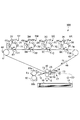
図1は、本発明の一実施例に係る画像形成装置100の概略縦断面図である。本実施例の画像形成装置100は、電子写真方式を利用してフルカラー画像を形成することのできる、中間転写方式を採用したタンデム型の画像形成装置である。
Example 1
1. Overall Configuration and Operation of Image Forming Apparatus FIG. 1 is a schematic longitudinal sectional view of an
画像形成装置100は、複数の画像形成部(ステーション)として、それぞれイエロー(Y)、マゼンダ(M)、シアン(C)、ブラック(K)のトナー像を形成する第1、第2、第3、第4の画像形成部SY、SM、SC、SKを有する。各画像形成部SY、SM、SC、SKにおける同一又は対応する機能あるいは構成を有する要素については、いずれかの色用の要素であることを表す符号の末尾のY、M、C、Kを省略して総括的に説明することがある。本実施例では、画像形成部Sは、後述する感光ドラム1、帯電ローラ2、露光装置3、現像装置4、一次転写ローラ6、ドラムクリーニング装置7などを有して構成される。
The
画像形成部Sは、トナー像を担持する像担持体(第1の像担持体)としての、ドラム型の電子写真感光体(感光体)である感光ドラム1を有する。感光ドラム1は、図中矢印R1方向(反時計回り)に回転駆動される。感光ドラム1は、円筒形の導電性基体の外周面に感光層が形成されて構成されている。本実施例では、感光ドラム1は、例えば350mm/secの周速度(プロセススピード)で回転駆動される。回転する感光ドラム1の表面は、帯電手段としてのローラ型の帯電部材である帯電ローラ2によって、所定の極性(本実施例では負極性)の所定の電位に一様に帯電される。帯電ローラ2は、感光ドラム1に接触して配置されている。帯電工程時に、帯電ローラ2には、所定の帯電電圧(帯電バイアス)が印加される。本実施例では、感光ドラム1の表面は、帯電ローラ2によって、例えば−450Vの暗部電位に帯電させられる。帯電した感光ドラム1の表面は、露光手段としての露光装置(レーザースキャナ)3によって、画像情報に応じてレーザ光が照射され、感光ドラム1上に静電像(静電潜像)が形成される。露光装置3は、各画像形成部Sに対応する色の分解色画像を展開した走査線画像データに応じてON−OFF変調したレーザービームを回転ミラーで走査して、帯電した感光ドラム1の表面に静電像を書き込む。露光装置3によって感光ドラム1に書き込まれる静電像は、小さいドット画像の集合体であるので、このドット画像の密度を変化させれば感光ドラム1の表面に形成されるトナー像の濃度を変化させることができる。 The image forming section S has a photosensitive drum 1 which is a drum-shaped electrophotographic photosensitive member (photosensitive member) as an image bearing member (first image bearing member) carrying a toner image. The photosensitive drum 1 is rotationally driven in the direction of the arrow R1 (counterclockwise) in the drawing. The photosensitive drum 1 is configured by forming a photosensitive layer on the outer peripheral surface of a cylindrical conductive substrate. In the present embodiment, the photosensitive drum 1 is rotationally driven at, for example, a circumferential speed (process speed) of 350 mm / sec. The surface of the rotating photosensitive drum 1 is uniformly charged to a predetermined potential of a predetermined polarity (negative in this embodiment) by a charging roller 2 which is a roller type charging member as charging means. The charging roller 2 is disposed in contact with the photosensitive drum 1. At the time of the charging step, a predetermined charging voltage (charging bias) is applied to the charging roller 2. In the present embodiment, the surface of the photosensitive drum 1 is charged by the charging roller 2 to a dark portion potential of, for example, -450V. The charged surface of the photosensitive drum 1 is irradiated with laser light according to image information by an exposure device (laser scanner) 3 as an exposure unit, and an electrostatic image (electrostatic latent image) is formed on the photosensitive drum 1. Ru. The exposure device 3 scans a laser beam which is ON-OFF modulated according to scanning line image data obtained by developing a color separation image corresponding to each image forming unit S with a rotating mirror to charge the surface of the photosensitive drum 1 charged. Write an electrostatic image to The electrostatic image written on the photosensitive drum 1 by the exposure device 3 is a collection of small dot images, so changing the density of this dot image changes the density of the toner image formed on the surface of the photosensitive drum 1 It can be done.
感光ドラム1上に形成された静電像は、現像手段としての現像装置4によって現像剤を用いて現像(可視化)され、感光ドラム1上にトナー像が形成される。本実施例では、感光ドラム1上の、一様に帯電処理された後に露光されることで電位の絶対値が低下した露光部に、感光ドラム1の帯電極性と同極性(本実施例では負極性)に帯電したトナーが付着する(イメージ部露光、反転現像)。本実施例では、現像装置4は、現像剤としてトナー(非磁性トナー粒子)とキャリア(磁性キャリア粒子)とを備えた二成分現像剤を用いる。現像装置4は、感光ドラム1の表面との間にわずかな隙間を隔てて配置された現像剤担持体としての現像スリーブ5を有する。本実施例では、現像スリーブ5は、その表面が感光ドラム1との対向部において感光ドラム1の表面の移動方向とは逆方向(カウンタ方向)に移動するように回転駆動される。現像装置4は、トナーとキャリアとを含む二成分現像剤を帯電させ、現像スリーブ5に担持させて、感光ドラム1との対向部へ搬送する。そして、例えばDC成分が−300Vとなるような現像電圧(現像バイアス)が現像スリーブ5に印加されることで、負極性に帯電したトナーが相対的に正極性になった感光ドラム1上の露光部へ移動して、静電像が現像される。本実施例では、現像時のトナーの帯電極性であるトナーの正規の帯電極性は負極性である。 The electrostatic image formed on the photosensitive drum 1 is developed (visualized) using a developer by a developing device 4 as a developing means, and a toner image is formed on the photosensitive drum 1. In this embodiment, the exposure polarity on the photosensitive drum 1 is the same as the charging polarity of the photosensitive drum 1 (in this embodiment, the negative polarity) in the exposed portion where the absolute value of the potential is lowered by exposure after being uniformly charged. (Toner image development, reversal development). In this embodiment, the developing device 4 uses a two-component developer including toner (nonmagnetic toner particles) and carrier (magnetic carrier particles) as a developer. The developing device 4 has a developing sleeve 5 as a developer carrying member disposed with a slight gap between the developing device 4 and the surface of the photosensitive drum 1. In the present embodiment, the developing sleeve 5 is rotationally driven so that the surface thereof moves in a direction (counter direction) opposite to the moving direction of the surface of the photosensitive drum 1 at the portion facing the photosensitive drum 1. The developing device 4 charges a two-component developer including toner and a carrier, causes the developing sleeve 5 to carry the two-component developer, and conveys the two-component developer to a portion facing the photosensitive drum 1. Then, for example, by applying a developing voltage (developing bias) such that the DC component becomes -300 V to the developing sleeve 5, exposure on the photosensitive drum 1 in which the negatively charged toner has become relatively positive The image is moved to the section to develop the electrostatic image. In this embodiment, the regular charging polarity of the toner, which is the charging polarity of the toner at the time of development, is negative.
各感光ドラム1Y、1M、1C、1Kの図中下方には、トナー像を担持する像担持体(第2の像担持体)としての、無端状のベルトで構成された中間転写体である中間転写ベルト40が配置されている。中間転写ベルト40は、張架手段としての複数の張架ローラ(支持ローラ)であるテンションローラ41、二次転写内ローラ42及び駆動ローラ43に掛け回されて張架されている。なお、本実施例では、中間転写ベルト40の内周面側には、押圧部材としての押圧ローラ25が更に設けられているが、これについては後述して詳しく説明する。押圧ローラ25は、複数の張架ローラには含まれないものとする。中間転写ベルト40は、駆動ローラ43が回転駆動されることによって、図中矢印R2方向(時計回り)に、感光ドラム1の周速度と略同一の周速度(プロセス速度)で回転(周回移動)する。中間転写ベルト40の内周面側には、各感光ドラム1に対応して、一次転写手段としてのローラ型の一次転写部材である一次転写ローラ6が配置されている。中間転写ベルト40は、一次転写ローラ6によって内周面側から外周面側(感光ドラム1側)に向けて押圧され、これにより感光ドラム1と中間転写ベルト40とが接触する一次転写部(一次転写ニップ)T1が形成される。上述のように感光ドラム1上に形成されたトナー像は、一次転写部T1において、一次転写ローラ6の作用によって、回転する中間転写ベルト40上に転写(一次転写)される。一次転写工程時に、一次転写ローラ6には、トナーの正規の帯電極性とは逆極性の直流電圧である一次転写電圧(一次転写バイアス)が印加される。例えばフルカラー画像の形成時には、各感光ドラム1上に形成されたイエロー、マゼンタ、シアン、ブラックの各色のトナー像が、中間転写ベルト40上に重ね合わされるようにして順次転写される。
Below the
中間転写ベルト40の外周面側には、二次転写内ローラ42に対応して、二次転写手段としてのローラ型の二次転写部材である二次転写外ローラ50が配置されている。中間転写ベルト40は、二次転写外ローラ50によって外周面側から内周面側(二次転写内ローラ42側)に向けて押圧され、これにより中間転写ベルト40と二次転写外ローラ50とが接触する二次転写部(二次転写ニップ)T2が形成される。上述のように中間転写ベルト40上に形成されたトナー像は、二次転写部T2において、二次転写外ローラ50の作用によって、中間転写ベルト40と二次転写外ローラ50とに挟持されて搬送される記録材P上に転写(二次転写)される。二次転写工程時に、二次転写外ローラ50には、二次転写電源Eにより、トナーの正規の帯電極性とは逆極性の直流電圧である二次転写電源(二次転写バイアス)が印加される。
On the outer peripheral surface side of the
記録材(例えば、紙、透明フィルム)Pは、カセット10に積載されて収納されており、給送ローラ11などによって1枚ずつ分離されて給送され、搬送ローラ12などによってレジストローラ13へと搬送される。そして、レジストローラ13が、中間転写ベルト40上のトナー像とタイミングを合わせるようにして、二次転写部T2に記録材Pを送り出す。レジストローラ13が記録材Pを送り出す先には、互いに対向するように配置された上ガイド14及び下ガイド15を備えた搬送ガイド17が設けられている。記録材Pは、この搬送ガイド17の上ガイド14と下ガイド15との間に送り出される。上ガイド14及び下ガイド15の配置や作用については、後述して詳しく説明する。また、二次転写部T2を通過した記録材Pは、転写後ガイド部材16によってガイドされて、定着手段としての定着装置60へと搬送される。定着装置60は、互いに当接して定着部(定着ニップ)T3を形成する2つの回転体である定着ローラ60aと加圧ローラ60bとを有する。定着ローラ60aは、その内部(中空部)に配置されたランプヒータなどの加熱体(図示せず)によって加熱され、加圧ローラ60bは付勢機構(図示せず)によって加熱ローラ60aに圧接させられている。記録材Pは、定着部T3で定着ローラ60aと加圧ローラ60bとによって挟持されて搬送されることで加熱及び加圧されて、トナー像が定着(溶融固着)される。その後、記録材Pは画像形成装置100の装置本体の外部に排出(出力)される。
The recording material (for example, paper, transparent film) P is stacked and stored in the
また、一次転写工程時に中間転写ベルト40に転写されずに感光ドラム1の表面に残留したトナー(一次転写残トナー)は、感光体クリーニング手段としてのドラムクリーニング装置7によって感光ドラム1の表面から除去されて回収される。ドラムクリーニング装置7は、感光ドラム1の表面に当接するクリーニングブレードによって、回転する感光ドラム1の表面を摺擦して、一次転写残トナーを回収する。このクリーニングブレードは、ポリウレタンなどの弾性材料で形成された板状部材であり、その先端が感光ドラム1の表面にカウンタ方向(自由端が感光ドラム1の表面の移動方向の上流側を向く方向)に当接させられている。また、中間転写ベルト40の外周面側において、テンションローラ41と対向する位置には、中間転写体クリーニング手段としてのベルトクリーニング装置44が配置されている。二次転写工程時に記録材Pに転写されずに中間転写ベルト40の表面に残留したトナー(二次転写残トナー)は、ベルトクリーニング装置44によって中間転写ベルト40の表面から除去されて回収される。ベルトクリーニング装置44は、中間転写ベルト40の表面に当接するクリーニングブレードによって、回転する中間転写ベルト40の表面を摺擦して、二次転写残トナーや二次転写部T2で中間転写ベルト40の表面に付着した紙粉などを回収する。このクリーニングブレードは、上記同様、ポリウレタンなどの弾性材料で形成された板状部材であり、その先端が中間転写ベルト40の表面にカウンタ方向(自由端が中間転写ベルト40の表面の移動方向の上流側を向く方向)に当接させられている。
Further, toner (primary transfer residual toner) remaining on the surface of the photosensitive drum 1 without being transferred to the
2.転写に関する構成
<一次転写ローラ>
一次転写ローラ6は、中間転写ベルト40に圧接して、感光ドラム1と中間転写ベルト40との間に一次転写部T1を形成する。本実施例では、一次転写ローラ6は、感光ドラム1に支持された中間転写ベルト40に、例えば総荷重1、5kgfで当接し、中間転写ベルト40に従動して回転する。本実施例では、一次転写ローラ6は、導電性金属で形成された直径8mmの円柱型部材を、電気抵抗値が5.0×10⁶Ω/cm、厚さが1.0mmの導電性発泡体の弾性層で覆って構成されている。また、本実施例では、一次転写ローラ6は、その回転中心を通る鉛直線を、感光ドラム1の回転中心を通る鉛直線よりも、中間転写ベルト40の回転方向に関し下流側へシフトさせて配置されている。なお、上記一次転写ローラ6の回転中心を通る鉛直線は、中間転写ベルト40の面と略直交する。また、上記感光ドラム1の回転中心を通る鉛直線は、中間転写ベルト40の面と略直交する。本実施例では、このシフト量は2.5mmである。
2. Configuration concerning transfer <Primary transfer roller>
The primary transfer roller 6 is in pressure contact with the
<中間転写ベルト>
無端ベルト状の像担持体としての中間転写ベルト40は、感光ドラム1に当接して回転する。中間転写ベルト40は、感光ドラム1から一次転写されたトナー像を記録材Pに二次転写するために搬送する中間転写体の一例である。中間転写ベルト40は、樹脂材料を用いて無端状に形成されており、その内周側に複数の張架ローラであるテンションローラ41、二次転写内ローラ42及び駆動ローラ43が当接するようにして設けられている。中間転写ベルト40は、これらテンションローラ41、二次転写内ローラ42及び駆動ローラ43に一定の張力で張架されている。本実施例では、上記3個の張架ローラのうち駆動ローラ43は、中間転写ベルト40の回転方向に関し二次転写内ローラ42の上流側に二次転写内ローラ42と隣り合って配置され、二次転写内ローラ42との間で中間転写ベルト40を張架する。また、上記3個の張架ローラのうち駆動ローラ43は、中間転写ベルト40の回転方向に関し駆動ローラ43の上流側に駆動ローラ43と隣り合って配置されたテンションローラ41との間で、中間転写ベルト40を張架する。なお、中間転写ベルト40の裏面とは、中間転写ベルト40のトナー像を担持する面(トナー像担持面)とは反対側の面、つまり、中間転写ベルト40の内周側の面のことをいう。また、中間転写ベルト40の表面とは、中間転写ベルト40のトナー像を担持する面、つまり、中間転写ベルト40の外周側の面のことをいう。
<Intermediate transfer belt>
The
中間転写ベルト40としては、単層又は多層構造の樹脂系材料で構成され、厚みが40μm以上、ヤング率が1.0GPa以上、表面抵抗率が1.0×10⁹〜1.0×10¹³Ω/□であるものを好ましく用いることができる。本実施例では、中間転写ベルト40は、厚さ85μmのポリイミド樹脂フィルムを基材として構成されており、カーボンブラックを分散させて表面抵抗率が1.0×1011Ω/□、体積抵抗率が1.0×109Ω・cmとなるように電気抵抗が調整されている。ただし、これに限定されるものではなく、例えば、表面抵抗率が1.0×109〜1.0×1014Ω/□(体積抵抗率が1.0×107〜1.0×1012Ω・cm)、厚みが45〜100μmの範囲の中間転写ベルトも同様に用いることができる。
The
<張架ローラ及び二次転写外ローラ>
本実施例では、駆動ローラ43は、金属製の芯金上に表層としての導電性ゴム層を有するゴムローラである。駆動ローラ43の芯金は電気的に接地(グランドに接続)されている。駆動ローラ43は、中間転写ベルト40の回転方向に関し画像形成位置(一次転写部)T1の下流側かつ二次転写内ローラ42の上流側に配置された上流ローラの一例である。
<Stretch roller and secondary transfer outer roller>
In the present embodiment, the
また、本実施例では、テンションローラ41は、金属製のローラである。テンションローラ41は、その回転軸線方向の両端部において、付勢手段としての弾性部材であるテンションバネ(図示せず)によって、中間転写ベルト40の内周面側から外周面側に向けて付勢されている。
Further, in the present embodiment, the
また、本実施例では、二次転写内ローラ42は、表層に導電性ゴム層を有したソリッドローラである。二次転写内ローラ23の外径は、一例としてφ20mmである。
Further, in the present embodiment, the secondary transfer
また、本実施例では、二次転写外ローラ50はスポンジローラであり、SUS(ステンレススチール)の芯金上に表層としての導電性スポンジゴム(スポンジ層)を有する。二次転写外ローラ24の外径は、一例としてφ24mmである。二次転写外ローラ50は、二次転写内ローラ42に対して中間転写ベルト40の回転方向に関し上流側にシフト(オフセット)して配置されている。このシフト量は、一例として3mmである。また、二次転写外ローラ50は、その回転軸線方向の両端部において、付勢手段としての弾性部材であるバネ(図示せず)によって、二次転写内ローラ42側に向けて中間転写ベルト40の面に対して略垂直方向に付勢されている。なお、本実施例では、二次転写外ローラ50は、中間転写ベルト40を介して二次転写内ローラ42と当接する。二次転写外ローラ50を二次転写内ローラ42に対して上流側にシフトして配置することで、二次転写部T2の上流における記録材Pと中間転写ベルト40との密着性を向上させ、転写性を向上させることができる。
Further, in this embodiment, the secondary transfer
本実施例では、二次転写内ローラ42と二次転写外ローラ50とによって、二次転写部T2においてトナー像を中間転写ベルト40から記録材Pに転写させる電界が形成される。本実施例では、二次転写外ローラ50にトナーの正規の帯電極性とは逆極性の二次転写バイアスが印加され、二次転写内ローラ42は電気的に接地されている。別法として、二次転写内ローラ42にトナーの正規の帯電極性と同極性の二次転写バイアスを印加し、二次転写外ローラ50を電気的に接地してもよい。
In this embodiment, the secondary transfer
本実施例では、中間転写ベルト40の複数の張架ローラとしての駆動ローラ43、テンションローラ41及び二次転写内ローラ42のそれぞれの回転軸線方向は略平行である。また、これら複数の張架ローラ41、42、43、二次転写外ローラ50、及び後述する押圧ローラ25のそれぞれの回転軸線方向も略平行である。
In this embodiment, the rotational axis directions of the
なお、本実施例では、駆動ローラ43が中間転写ベルト40の回転方向に関し二次転写内ローラ42の上流側かつ画像形成部Sの下流側に配置された上流ローラであるが、テンションローラ41が上流ローラであってもよい。その場合、本実施例におけるテンションローラ41の位置に駆動ローラ43を配置すればよい。
In the present embodiment, the driving
3.押圧部材
図2は、本実施例における二次転写部T2の近傍の概略縦断面図(二次転写内ローラ42の回転軸線方向と略直交する断面)である。本実施例の画像形成装置100は、中間転写ベルト40を裏面側から押圧し、中間転写ベルト40をその表面側へ張り出させる押圧部材(振動防止部材)として、ローラ状の部材である押圧ローラ25を有する。押圧ローラ25は、中間転写ベルト40の回転方向に関し二次転写内ローラ42の上流側、かつ、駆動ローラ43の下流側において中間転写ベルト40を内周面側から外周面側に向けて押圧するように配置されている。押圧ローラ25は、中間転写ベルト40の回転方向に関し、二次転写内ローラ42の上流側に二次転写ローラ42と隣り合って配置され、また駆動ローラ43の下流側に駆動ローラ43と隣り合って配置されている。特に、この押圧ローラ25は、中間転写ベルト40と二次転写内ローラ42とが接触する領域(二次転写部)T2から中間転写ベルト40の回転方向の上流側へ25mm以内の中間転写ベルト40を押圧するように配置されている。このように、二次転写内ローラ42から中間転写ベルト40の回転方向上流側へ25mm以内の中間転写ベルト40を押圧するように押圧ローラ25を配置することで、中間転写ベルト40の波打ちや振動を抑制する効果が得られる。
3. Pressing Member FIG. 2 is a schematic longitudinal cross-sectional view (a cross section substantially orthogonal to the rotation axis direction of the secondary transfer inner roller 42) in the vicinity of the secondary transfer portion T2 in the present embodiment. The
押圧ローラ25は、例えば、中間転写ベルト40を張架する複数の張架ローラ41、42、43が組み付けられた転写ユニットフレーム(図示せず)や、画像形成装置100の装置本体のフレーム(図示せず)などに回転自在に支持されている。本実施例では、押圧ローラ25は、SUS製のローラ(金属ローラ)である。なお、本実施例では、押圧ローラ25は、抵抗体(バリスタなど)を介して電気的に接地されており、二次転写外ローラ50に二次転写電圧が印加された際に押圧ローラ25に電流が流れ込むことが抑制されている。押圧ローラ25の回転軸線方向の長さは、中間転写ベルト40の回転方向と略直交する方向の長さ(幅)と同等であり、押圧ローラ25は中間転写ベルト40の略全幅にわたり当接する。押圧ローラ25は、中間転写ベルト40に接触した状態で中間転写ベルト40の回転に伴って従動して回転する。
The
押圧ローラ25は、二次転写部T2の近傍で中間転写ベルト40が振動したり波打ちしたりして姿勢が安定せず、記録材Pと中間転写ベルト40との密着性が損なわれることがないよう、下記の押圧量Yが予め決められ、該押圧量Yにあわせた位置に配置される。
In the
図2において、中間転写ベルト40が掛け回される側の二次転写内ローラ42と駆動ローラ43との共通の接線を基準線Lとする。また、基準線Lと略平行な、押圧ローラ25が中間転写ベルトと接触する領域における中間転写ベルト40の接線を押圧部接線Ldとする。このとき、基準線Lと押圧部接線Ldとの間の距離を、押圧ローラ25の中間転写ベルト40に対す押圧量Yとする。
In FIG. 2, a common tangent between the secondary transfer
本発明者の検討によれば、本実施例の構成では、押圧量Yが、0.5mmより大きく、3.5mm以下の場合に、中間転写ベルト40の振動や波打ちを抑制するのに効果的であることがわかった。すなわち、本実施例の構成では、0.5mm<Y≦3.5mmの関係を満たすことが好ましい。押圧量Yが0.5mm以下である場合、中間転写ベルト40の振動や波打ちを抑制することが困難となり、中間転写ベルト40と記録材Pとの間での異常放電が原因の画像不良が発生することがある。一方、押圧量Yが3.5mmより大きい場合、押圧ローラ25と中間転写ベルト40との接触面にかかる負荷が増加するので、中間転写ベルト40はスムーズに回転しにくくなる。
According to the study of the present inventor, in the configuration of the present embodiment, when the pressing amount Y is larger than 0.5 mm and smaller than 3.5 mm, it is effective to suppress the vibration and waving of the
また、押圧ローラ25は、記録材Pと中間転写ベルト40との間に隙間(ギャップ)が生じないよう、下記の二次転写外ローラ50と押圧ローラ25との離間距離Xが予め決められ、上記押圧量Yと共に該離間距離Xに合わせた位置に配置される。
Further, in the
図2において、二次転写内ローラ42の回転中心を通り基準線Lと略直交する直線を内ローラ中心線Laとする。また、二次転写外ローラ50の回転中心を通り基準線Lと略直交する直線を外ローラ中心線Lbとする。また、中間転写ベルト40と押圧部接線Ldとの接点を通り基準線Lと略直交する直線を押圧部垂線Lcとする。本実施例では、押圧ローラ25の回転中心を通り基準線Lと略直交する直線が、上記押圧部垂線(押圧ローラ中心線)Lcとなる。このとき、外ローラ中心線Lbと押圧部垂線Lcとの間の距離を、二次転写外ローラ50と押圧ローラ25との離間距離Xとする。また、内ローラ中心線Laと外ローラ中心線Lbとの間の距離をL1(ただし、外ローラ中心線Lbが内ローラ中心線Laより中間転写ベルト40の回転方向に関し上流側にあるとき正の値)とする。この距離L1は、二次転写内ローラ23に対する二次転写外ローラ24のシフト量に相当する(以下「シフト量L1」ともいう。)。また、二次転写内ローラ42の半径をR1、押圧ローラ25の半径をR2とする。
In FIG. 2, a straight line that passes through the rotation center of the secondary transfer
本発明者の検討によれば、本実施例の構成では離間距離Xが、(((R1+R2)2−(R1−R2)2))1/2−L1)+7mmより大きく、25mmより小さい場合に、中間転写ベルト40の振動や波打ちを抑制するのにより効果的であることがわかった。また、この場合に、記録材Pと中間転写ベルト40との間に隙間(ギャップ)が生じないようにするのに効果的であることがわかった。すなわち、本実施例の構成では、(((R1+R2)2−(R1−R2)2))1/2−L1)+7mm<X<25mmの関係を満たすことが好ましい。離間距離Xを小さくし過ぎると、押圧ローラ25が二次転写内ローラ42及び二次転写外ローラ50の駆動を阻害してしまうことがある。二次転写内ローラ42や二次転写外ローラ50の駆動が阻害されると、中間転写ベルト40が滑らかに駆動されなくなる。そして、中間転写ベルト40が滑らかに駆動されていない場合に一次転写や二次転写が行われると、トナー像が所定位置からずれてしまう画像不良が発生することがある。一方、離間距離Xが25mmより大きい場合、中間転写ベルト40の振動や波打ちを抑制する効果が低減し、中間転写ベルト40と記録材Pとの間の異常放電が原因の画像不良が発生する可能性がある。
According to the study of the inventor of the present invention, in the configuration of the present embodiment, when the separation distance X is larger than (((R1 + R2) 2- (R1-R2) 2 ) 1 / 2- L1) +7 mm and smaller than 25 mm. It has been found that suppressing the vibration and waving of the
本実施例では、二次転写内ローラ42の半径R1は10mm、押圧ローラ25の半径R2は3mm、二次転写外ローラ50の半径は12mm、シフト量L1は3mmである。そして、((R1+R2)2−(R1−R2)2))1/2−L1=7.9mmである。
In this embodiment, the radius R1 of the secondary transfer
なお、上述の押圧量Y、離間距離Xの好ましい範囲は、評価用の画像を出力した際の転写不良の発生の有無の評価、二次転写部T2の近傍の中間転写ベルト40の変位の観察、中間転写ベルト40の走行安定性の観察を通して実験的に求めた。この実験は、押圧ローラ25の有無、押圧ローラ25の位置(押圧量Y、離間距離X)、押圧ローラ25、二次転写内ローラ42及び二次転写外ローラ50の外径、記録材Pの種類を種々変更して繰り返し行った。
The preferable range of the pressing amount Y and the separation distance X described above is the evaluation of the presence or absence of the occurrence of the transfer failure when the image for evaluation is output, and the observation of the displacement of the
4.搬送ガイド
次に、本実施例における搬送ガイド17の構成及び配置について説明する。
4. Conveyance Guide Next, the configuration and arrangement of the
画像形成装置100は、搬送手段としてのレジストローラ(レジストローラ対、レジユニット)13によって二次転写部T2へと搬送される記録材Pを案内する、ガイド手段としての搬送ガイド17を有する。搬送ガイド17は、記録材Pが中間転写ベルト40に近づく動きを規制する第1のガイド部材としての上ガイド14と、記録材Pが中間転写ベルト40から離れる動きを規制する第2のガイド部材としての下ガイド15と、を有する。上ガイド14と下ガイド15とは、中間転写ベルト40の外側(表面側)に、記録材Pの搬送方向に沿って上下二段に配置されている。上ガイド14は、下ガイド15よりも中間転写ベルト40に近接して配置され、下ガイド15は、上ガイド14と対向するように、上ガイド14よりも中間転写ベルト40から離れて配置されている。つまり、上ガイド14は、下ガイド15と中間転写ベルト40との間に配置されている。
The
本実施例では、上ガイド14、下ガイド15は、それぞれ記録材Pの搬送方向と略直交する方向(長手方向)に連続する板状の部材である。上ガイド14、下ガイド15の長手方向の長さは、画像形成装置100において画像を形成することが可能な記録材Pの同方向の幅と同等である。ただし、上ガイド14、下ガイド15は、上述のような連続する板状の部材に限定されるものではなく、例えば記録材Pの搬送方向と略直交する方向において複数に分割されていたり、同方向における記録材Pの移動経路の一部にのみ設けられたりしていてもよい。
In the present embodiment, the
そして、図2に示すように、上ガイド14は、その二次転写部T2側(中間転写ベルト40の回転方向に関し下流側)の先端14aが、押圧部垂線Lcに対して二次転写部T2側に位置するように配置されている。つまり、中間転写ベルト40の回転方向に関し、上ガイド14の下流側の先端14aは、押圧部垂線Lcに対して下流側、かつ、二次転写部T2に対して上流側に位置する。換言すると、基準線Lと略平行な方向における二次転写外ローラ50の回転中心からの距離は、上ガイド14の先端14aの方が、押圧ローラ25の回転中心よりも近い。
Then, as shown in FIG. 2, the
なお、本実施例では、下ガイド15も、その二次転写部T2側(中間転写ベルト40の回転方向に関し下流側)の先端が、押圧部垂線Lcに対して二次転写部T2側に位置するように配置されている。つまり、中間転写ベルト40の回転方向に関し、下ガイド15の下流側の先端は、押圧部垂線Lcに対して下流側、かつ、二次転写部T2に対して上流側に位置する。
In the present embodiment, the
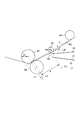
図3は、本実施例における、記録材Pが搬送ガイド17によって案内されて二次転写部T2に搬送されている様子を示す、二次転写部T2の近傍の概略縦断面図(二次転写内ローラ42の回転軸線方向と略直交する断面)である。本実施例では、上ガイド14の先端14aが上記位置に配置されることで、押圧ローラ25が中間転写ベルト40を押圧している位置で記録材Pと中間転写ベルト40とが接触することが抑制される。
FIG. 3 is a schematic vertical cross-sectional view of the vicinity of the secondary transfer portion T2 (secondary transfer (secondary transfer), showing how the recording material P is guided by the
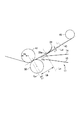
一方、図4は、比較例における、記録材Pが搬送ガイド17によって案内されて二次転写部T2に搬送されている様子を示す、二次転写部T2の近傍の概略縦断面図(二次転写内ローラ42の回転軸線方向と略直交する断面)である。この比較例の画像形成装置100では、上ガイド14は、その二次転写ニップT2側(中間転写ベルト40の回転方向に関し下流側)の先端14aが、押圧部垂線Lcに対して中間転写ベルト40の回転方向に関し上流側に位置するように配置されている。比較例では、上ガイド14の先端14aが上記位置に配置されることで、押圧ローラ25が中間転写ベルト40を押圧している位置で記録材Pと中間転写ベルト40とが接触することがある。なお、比較例の画像形成装置100は、上記の点を除いて本実施例の画像形成装置100と同じ構成を有する(比較例においても本実施例のものと同一又は対応する機能あるいは構成を有する要素には本実施例と同一の符号を付している。)。
On the other hand, FIG. 4 is a schematic longitudinal sectional view in the vicinity of the secondary transfer portion T2 showing a state where the recording material P is guided by the
図5は、本実施例と比較例とについて、中間転写ベルト40の回転方向に関し押圧ローラ25が中間転写ベルト40を押圧している位置から二次転写部T2までの間における記録材Pと中間転写ベルト40との接触圧を比較した実験の結果を示している。ここでは、記録材Pと中間転写ベルト40との接触圧は、記録材Pとして厚紙の一例であるmondi color copy coated silk 200gsm用い、紙搬送の2次元シミュレーションを用いて計算した。
FIG. 5 shows the recording material P and the intermediate between the position where the
図5に示すように、本実施例では、押圧ローラ25が中間転写ベルト40を押圧している位置で記録材Pと中間転写ベルトとが接触することが抑制される。そのため、押圧ローラ25が中間転写ベルト40を押圧している位置で、記録材Pと中間転写ベルト40との接触圧が大きくなることはない。これに対して、比較例では、押圧ローラ25が中間転写ベルト40を押圧している位置で記録材Pと中間転写ベルト40とが接触すると、記録材Pと中間転写ベルト40との接触圧が大きくなることがわかった。そして、比較例では、この接触圧が大きくなる位置で、記録材Pと中間転写ベルト40とが強く擦れ、中間転写ベルト40に担持された未定着のトナー像が乱れ、その結果、その乱れたトナー像が記録材Pに転写されて画像不良が発生することがわかった。
As shown in FIG. 5, in the present embodiment, the contact between the recording material P and the intermediate transfer belt at the position where the
上述のような記録材Pと中間転写ベルト40とが擦れる現象は、次のような場合により顕著となる。つまり、記録材Pの搬送速度は、中間転写ベルト40の搬送速度よりも速く設定されることがある。これは、レジストローラ13の摩耗や、使用環境によるレジストローラ13の外径の変化によって、記録材Pの搬送速度が中間転写ベルト40の搬送速度よりも遅くなることを抑制するためである。この場合、記録材Pの搬送方向の先端が二次転写部T2に到達した後、記録材Pは二次転写部T2とレジストローラ13との間でループを形成するような搬送経路をとる。そのため、比較例では、記録材Pが上記ループを形成するような経路をとると、図6に示すように押圧ローラ25が中間転写ベルト40を押圧している位置で記録材Pと中間転写ベルト40とが接触し易くなる。そして、上述のように記録材Pと中間転写ベルト40とが強く擦れ、中間転写ベルト40に担持された未定着のトナー像が乱れ、その結果、その乱れたトナー像が記録材Pに転写されて画像不良が発生し易くなる。
The phenomenon that the recording material P and the
これに対し、本実施例では、中間転写ベルト40の回転方向に関し二次転写部T2の上流に押圧ローラ25が配置されていても、押圧ローラ25が中間転写ベルト40を押圧している位置で記録材Pと中間転写ベルト40とが接触することが抑制される。その結果、記録材Pと中間転写ベルト40との接触圧が大きくなることが抑制され、記録材Pと中間転写ベルト40とが擦れることを原因とする画像不良の発生が抑制される。
On the other hand, in the present embodiment, even when the
以上説明したように、本実施例によれば、中間転写ベルト40を内周面側から押圧して二次転写性を向上させつつ、記録材Pと中間転写ベルト40とが擦れることを原因とする画像不良を抑制することができる。
As described above, according to the present embodiment, the
[実施例2]
次に、本発明の他の実施例について説明する。本実施例の画像形成装置の基本的な構成及び動作は、実施例1のものと同じである。したがって、本実施例の画像形成装置において、実施例1の画像形成装置のものと同一又は対応する機能あるいは構成を有する要素については、実施例1と同一の符号を付して詳しい説明は省略する。
Example 2
Next, another embodiment of the present invention will be described. The basic configuration and operation of the image forming apparatus of this embodiment are the same as those of the first embodiment. Accordingly, in the image forming apparatus of the present embodiment, elements having the same or corresponding functions or configurations as those of the image forming apparatus of the first embodiment are designated by the same reference numerals as in the first embodiment, and detailed descriptions are omitted. .
1.押圧部材
図7は、本実施例における二次転写部T2の近傍の概略断面図(二次転写内ローラ42の回転軸線方向と略直交する断面)である。本実施例の画像形成装置100は、中間転写ベルト40を裏面側から押圧し、中間転写ベルト40をその表面側へ張り出させる押圧部材(振動防止部材)として、シート状の部材である押圧シート26を有する。押圧シート26は、中間転写ベルト40の回転方向に関し二次転写内ローラ42の上流側、かつ、駆動ローラ43の下流側において中間転写ベルト40を内周面側から外周面側に向けて押圧するように配置されている。特に、この押圧シート26は、中間転写ベルト40と二次転写内ローラ42とが接触する領域(二次転写部)T2から中間転写ベルト40の回転方向の上流側へ25mm以内の中間転写ベルト40を押圧するように配置されている。このように、二次転写内ローラ42から中間転写ベルト40の回転方向上流側へ25mm以内の中間転写ベルト40を押圧するように押圧シート26を配置することで、中間転写ベルト40の波打ちや振動を抑制する効果が得られる。
1. Pressing Member FIG. 7 is a schematic cross-sectional view (a cross section substantially orthogonal to the rotation axis direction of the secondary transfer inner roller 42) in the vicinity of the secondary transfer portion T2 in the present embodiment. The
押圧シート26は、樹脂材料を用いて形成された板状の部材である。押圧シート26を形成する樹脂としては、例えば、PET樹脂などのポリエステル樹脂などを好適に用いることができる。本実施例では、押圧シート26は、中間転写ベルト40の回転方向と略直交する方向と略平行に配置される長手方向と、該長手方向と略直交する短手方向とにそれぞれ所定の長さを有し、所定の厚みを有する板状の部材で構成されている。一例として、押圧シート26の厚みは0.4mm〜0.6mmである。また、一例として、押圧シート26の長手方向の長さは、中間転写ベルト40の回転方向と略直交する方向の長さ(幅)と同等の330mm〜380mmであり、押圧シート26は中間転写ベルト40の略全幅にわたり当接する。押圧シート26は、例えば、中間転写ベルト40を張架する複数の張架ローラ41、42、43が組み付けられた転写ユニットフレーム(図示せず)や、画像形成装置100の装置本体のフレーム(図示せず)などに支持されている。押圧シート26は、短手方向の一方の端部である自由端部が中間転写ベルト40に当接させられ、他方の端部である固定端部側が上記フレームなどに固定される。
The
例えば、押圧シート26としてPET樹脂シートを用いる場合、低い電気抵抗のPET樹脂シートを用いると、二次転写外ローラ50への二次転写電圧の印加に伴い押圧シート26に電流が流れて、転写不良を生じさせる可能性がある。反対に高い電気抵抗のPET樹脂シートを用いると、押圧シート26と中間転写ベルト40との摩擦によって静電気(摩擦帯電)が生じて、押圧シート26に中間転写ベルト40が吸着して中間転写ベルト40の回転を妨げる可能性がある。そのため、押圧シート26としては、中抵抗の電気抵抗(例えば、体積抵抗率が1×10⁵〜1×10⁹Ω・cm)に調整されたPET樹脂シートを用いることが好ましい。
For example, when a PET resin sheet is used as the
押圧シート26は、二次転写部T2の近傍で中間転写ベルト40が振動したり波打ちしたりして姿勢が安定せず、記録材Pと中間転写ベルト40との密着性が損なわれることがないよう、下記の押圧量Yが予め決められ、該押圧量Yにあわせた位置に配置される。
In the
図7において、中間転写ベルト40が掛け回される側の二次転写内ローラ42と駆動ローラ43との共通の接線を基準線Lとする。また、基準線Lと略平行な、押圧シート26が中間転写ベルトと接触する領域における中間転写ベルト40の接線を押圧部接線Ldとする。このとき、基準線Lと押圧部接線Ldとの間の距離を、押圧シート26の中間転写ベルト40に対する押圧量Yとする。
In FIG. 7, a common tangent between the secondary transfer
本発明者の検討によれば、本実施例の構成では、押圧量Yが、1.0mm以上、3.0mm以下の場合に、中間転写ベルト40の振動や波打ちを抑制するのに効果的であることがわかった。すなわち、本実施例の構成では、1.0mm≦Y≦3.0mmの関係を満たすことが好ましい。押圧量Yが1.0mmより小さい場合、中間転写ベルト40の振動や波打ちを抑制することが困難となり、中間転写ベルト40と記録材Pとの間での異常放電が原因の画像不良が発生することがある。一方、押圧量Yが3.0mmより大きい場合、押圧シート26と中間転写ベルト40との接触面にかかる負荷が増加するので、中間転写ベルト40はスムーズに回転しにくくなる。
According to the study of the present inventor, in the configuration of this embodiment, when the pressing amount Y is 1.0 mm or more and 3.0 mm or less, it is effective to suppress the vibration and waving of the
また、押圧シート26は、記録材Pと中間転写ベルト40との間に隙間(ギャップ)が生じないよう、下記の二次転写外ローラ50と押圧シート26との離間距離Xが予め決められ、上記押圧量Yと共に該離間距離Xに合わせた位置に配置される。
Further, in the
図7において、二次転写外ローラ50の回転中心を通り基準線Lと略直交する直線を外ローラ中心線Lbとする。また、中間転写ベルト40と押圧部接線Ldとの接点を通り基準線Lと略直交する直線を押圧部垂線Lcとする。本実施例では、押圧シート26と中間転写ベルト40との接触領域のうち中間転写ベルト40の回転方向に関し最も下流側の位置(押圧シート26の先端)26aを通り基準線Lと略直交する直線が、上記押圧部垂線(押圧シート先端線)Lcとなる。このとき、外ローラ中心線Lbと押圧部垂線Lcとの間の距離を、二次転写外ローラ50と押圧シート26との離間距離Xとする。
In FIG. 7, a straight line that passes through the rotation center of the secondary transfer
本発明者の検討によれば、本実施例の構成では、離間距離Xが、3mm以上、15mm以下の場合に、中間転写ベルト40の振動や波打ちを抑制するのにより効果的であることがわかった。また、この場合に、記録材Pと中間転写ベルト40との間に隙間(ギャップ)が生じないようにするのに効果的であることがわかった。すなわち、本実施例の構成では、3mm≦X≦15mmの関係を満たすことが好ましい。離間距離Xを小さくし過ぎると、押圧シート26が二次転写内ローラ42及び二次転写外ローラ50の駆動を阻害してしまうことがある。一方、離間距離Xが15mmより大きい場合、中間転写ベルト40の振動や波打ちを抑制する効果が低減し、中間転写ベルト40と記録材Pとの間の異常放電が原因の画像不良が発生する可能性がある。
According to the study of the present inventor, it is found that the configuration of the present embodiment is more effective in suppressing the vibration and waving of the
なお、上述の押圧量Y、離間距離Xの好ましい範囲は、評価用の画像を出力した際の転写不良の発生の有無の評価、二次転写部T2の近傍の中間転写ベルト40の変位の観察、中間転写ベルト40の走行安定性の観察を通して実験的に求めた。この実験は、押圧シート26の有無、押圧シート26の位置(押圧量Y、離間距離X)、記録材Pの種類を種々変更して繰り返し行った。
The preferable range of the pressing amount Y and the separation distance X described above is the evaluation of the presence or absence of the occurrence of the transfer failure when the image for evaluation is output, and the observation of the displacement of the
また、押圧シート26は、中間転写ベルト40の回転を妨げない向きに配置されることが好ましい。そのため、本実施例では、押圧シート26は、中間転写ベルト40の回転方向に対して順方向、すなわち、押圧シート26の自由端側の先端26aが中間転写ベルト40の回転方向の下流側を向くように、中間転写ベルト40に当接させられている。また、押圧シート26が撓んで中間転写ベルト40を押し付けるため、押圧シート26はある程度の範囲をもって中間転写ベルト40に当接する。
Further, the
2.搬送ガイド
図7に示すように、上ガイド14は、その二次転写部T2側(中間転写ベルト40の回転方向に関し下流側)の先端14aが、押圧部垂線Lcに対して二次転写部T2側(中間転写ベルト40の回転方向に関し下流側)に位置するように配置される。換言すると、基準線Lと略平行な方向における二次転写外ローラ50の回転中心からの距離は、上ガイド14の先端14aの方が、押圧シート26の先端14a(押圧シート26と中間転写ベルト40との接触領域の最下流位置)よりも近い。
2. Conveying Guide As shown in FIG. 7, the
これにより、実施例1と同様の理由により、二次転写部T2の上流に押圧シート26が配置されていても、押圧シート26が中間転写ベルト40を押圧している位置で記録材Pと中間転写ベルト40とが接触することが抑制される。その結果、記録材Pと中間転写ベルト40との接触圧が大きくなることが抑制され、記録材Pと中間転写ベルト40とが擦れることを原因とする画像不良の発生が抑制される。
Thus, even if the
以上説明したように、本実施例によれば、実施例1と同様の効果を得ることができる。また、本実施例では、押圧部材が比較的簡易な構成のシート状の部材で構成されているので、構成の簡易化、小型化、低コスト化に有利である。 As described above, according to this embodiment, the same effect as that of the first embodiment can be obtained. Further, in the present embodiment, the pressing member is constituted by a sheet-like member having a relatively simple structure, which is advantageous for simplifying the structure, reducing the size and reducing the cost.
[その他]
以上、本発明を具体的な実施例に即して説明したが、本発明は上述の実施例に限定されるものではない。
[Others]
As mentioned above, although this invention was described based on the specific Example, this invention is not limited to the above-mentioned Example.
上述の実施例では、ベルト状の像担持体が中間転写ベルトである場合について説明したが、画像形成位置で担持されたトナー像を搬送する無端状のベルトで構成された像担持体であれば、本発明を適用することができる。このようなベルト状の像担持体としては、上述の実施例における中間転写ベルトの他、感光体ベルトや静電記録誘電体ベルトが例示できる。 In the above-described embodiment, the case where the belt-like image carrier is the intermediate transfer belt has been described, but in the case of an image carrier comprising an endless belt for conveying the toner image carried at the image forming position. The present invention can be applied. As such a belt-like image carrier, in addition to the intermediate transfer belt in the above-mentioned embodiment, a photosensitive belt and an electrostatic recording dielectric belt can be exemplified.
本発明は、上述の実施形態の構成の一部または全部を、その代替的な構成で置き換えた別の実施形態でも実施できる。したがって、ベルト状の像担持体を用いる画像形成装置であれば、タンデム型/1ドラム型、帯電方式、静電像形成方式、現像方式、転写方式、定着方式の区別無く実施できる。上述の実施例では、トナー像の形成/転写に係る主要部のみを説明したが、本発明は、必要な機器、装備、筐体構造を加えて、プリンタ、各種印刷機、複写機、FAX、複合機など、種々の用途で実施できる。 The present invention can be practiced in other embodiments in which part or all of the configuration of the above-described embodiment is replaced with its alternative configuration. Therefore, in the case of an image forming apparatus using a belt-like image carrier, the present invention can be implemented without distinction between the tandem type / single drum type, charging type, electrostatic image forming type, developing type, transfer type and fixing type. In the above embodiment, only the main part related to the formation / transfer of the toner image has been described. However, the present invention adds the necessary equipment, equipment, and housing structure to the printer, various printing machines, copiers, fax machines, It can be implemented in various applications such as multifunction machines.
1 感光ドラム
13 レジストローラ
14 上ガイド
15 下ガイド
25 押圧ローラ(押圧部材)
26 押圧シート(押圧部材)
40 中間転写ベルト
41 テンションローラ
42 二次転写内ローラ
43 駆動ローラ(上流ローラ)
50 二次転写外ローラ
100 画像形成装置
P 記録材
S 画像形成部
T2 二次転写部
1
26 Pressed sheet (pressing member)
40
50 secondary transfer
Claims (8)
前記ベルトの外周面に接触し、前記ベルトから記録材へトナー像を転写する転写部を形成する外ローラと、
前記ベルトを張架する複数の張架ローラであって、前記転写部に対応して配置された内ローラと、前記ベルトの移動方向に関し前記画像形成位置の下流側かつ前記内ローラの上流側に配置された上流ローラと、を含む複数の張架ローラと、
前記ベルトの移動方向に関し前記内ローラの上流側かつ前記上流ローラの下流側において前記ベルトを内周面側から外周面側に向けて押圧する押圧部材であって、前記ベルトと前記内ローラとが接触する領域から前記ベルトの移動方向の上流側へ25mm以内の前記ベルトを押圧するように配置された押圧部材と、
前記転写部に向けて記録材を搬送する搬送手段と、
前記搬送手段によって搬送され前記転写部に向かう記録材の前記ベルトに近づく動きを規制するガイド部材と、
を有する画像形成装置において、
前記内ローラの回転軸線方向と略直交する断面において、前記内ローラと前記上流ローラとの共通の接線を基準線L、前記基準線Lと略平行な、前記押圧部材が前記ベルトと接触する領域における前記ベルトの接線を押圧部接線Ld、前記ベルトと前記押圧部接線Ldとの接点を通り前記基準線Lと略直交する直線を押圧部垂線Lcとしたとき、前記ベルトの移動方向に関し、前記ガイド部材の下流側の先端は、前記押圧部垂線Lcに対して下流側、かつ、前記ベルトと前記外ローラとが接触する領域に対して上流側に位置することを特徴とする画像形成装置。 An endless belt for conveying a toner image carried at an image forming position;
An outer roller that contacts the outer circumferential surface of the belt and forms a transfer portion that transfers the toner image from the belt to the recording material;
A plurality of tension rollers for tensioning the belt, and an inner roller disposed corresponding to the transfer portion, downstream of the image forming position with respect to the moving direction of the belt and upstream of the inner roller A plurality of tensioning rollers, including an upstream roller disposed;
A pressing member that presses the belt from the inner circumferential surface toward the outer circumferential surface on the upstream side of the inner roller and the downstream of the upstream roller in the moving direction of the belt, the belt and the inner roller being A pressing member disposed so as to press the belt within 25 mm from the contact area to the upstream side in the moving direction of the belt;
Conveying means for conveying the recording material to the transfer unit;
A guide member that regulates movement of the recording material conveyed by the conveyance unit toward the transfer unit toward the belt;
In an image forming apparatus having
In a cross section substantially orthogonal to the rotation axis direction of the inner roller, a common tangent line between the inner roller and the upstream roller is a reference line L, and a region substantially parallel to the reference line L where the pressing member contacts the belt When the tangent of the belt at the point of the belt is the pressing portion tangent Ld, and a straight line substantially orthogonal to the reference line L passing through the contact point between the belt and the pressing portion tangent Ld is the pressing portion perpendicular Lc, the moving direction of the belt The image forming apparatus is characterized in that the downstream end of the guide member is located downstream with respect to the pressing portion normal line Lc and upstream with respect to a region where the belt and the outer roller contact with each other.
(((R1+R2)2−(R1−R2)2))1/2−L1)+7mm<X<25mm、
0.5mm<Y≦3.5mm、
の関係を満たす位置に配置されることを特徴とする請求項2に記載の画像形成装置。 In a cross section substantially orthogonal to the rotation axis direction of the inner roller, a straight line substantially perpendicular to the reference line L passing through the rotation center of the inner roller passes the rotation center of the inner roller center line La and the outer roller and the reference line L A straight line substantially orthogonal to the outer roller center line Lb, a straight line substantially perpendicular to the reference line L passing through the rotation center of the pressing member is the pressing portion perpendicular Lc, the inner roller center line La and the outer roller center line Lb L1 (where the outer roller center line Lb is a positive value when the outer roller center line Lb is upstream with respect to the moving direction of the belt with respect to the inner roller center line La), the outer roller center line Lb and the pressing portion perpendicular line Assuming that the distance between Lc and X is X, the distance between the reference line L and the pressing portion tangent Ld is Y, the radius of the inner roller is R1, and the radius of the pressing member is R2, the pressing member is ,
(((R1 + R2) 2- (R1-R2) 2 )) 1 / 2- L1) +7 mm <X <25 mm,
0.5 mm <Y ≦ 3.5 mm,
The image forming apparatus according to claim 2, wherein the image forming apparatus is disposed at a position satisfying the following relationship.
3mm≦X≦15mm、
1.0mm≦Y≦3.0mm、
の関係を満たす位置に配置されることを特徴とする請求項5に記載の画像形成装置。 In a cross section substantially orthogonal to the rotation axis direction of the inner roller, a straight line substantially perpendicular to the reference line L passing through the rotation center of the outer roller is an outer roller center line Lb, and a contact region between the pressing member and the belt A straight line substantially orthogonal to the reference line L passing through the most downstream position in the moving direction of the belt is a distance between the pressing portion perpendicular Lc and the outer roller center line Lb and the pressing portion perpendicular Lc as X. When the distance between the reference line L and the pressing portion tangent Ld is Y, the pressing member is
3 mm ≦ X ≦ 15 mm,
1.0 mm ≦ Y ≦ 3.0 mm,
The image forming apparatus according to claim 5, wherein the image forming apparatus is disposed at a position satisfying the following relationship.
Priority Applications (2)
| Application Number | Priority Date | Filing Date | Title |
|---|---|---|---|
| JP2017212278A JP2019086552A (en) | 2017-11-01 | 2017-11-01 | Image forming device |
| US16/175,881 US10551762B2 (en) | 2017-11-01 | 2018-10-31 | Image forming apparatus having guiding member for regulating approach of recording material toward transfer belt |
Applications Claiming Priority (1)
| Application Number | Priority Date | Filing Date | Title |
|---|---|---|---|
| JP2017212278A JP2019086552A (en) | 2017-11-01 | 2017-11-01 | Image forming device |
Publications (1)
| Publication Number | Publication Date |
|---|---|
| JP2019086552A true JP2019086552A (en) | 2019-06-06 |
Family
ID=66243797
Family Applications (1)
| Application Number | Title | Priority Date | Filing Date |
|---|---|---|---|
| JP2017212278A Pending JP2019086552A (en) | 2017-11-01 | 2017-11-01 | Image forming device |
Country Status (2)
| Country | Link |
|---|---|
| US (1) | US10551762B2 (en) |
| JP (1) | JP2019086552A (en) |
Cited By (3)
| Publication number | Priority date | Publication date | Assignee | Title |
|---|---|---|---|---|
| WO2020217831A1 (en) | 2019-04-26 | 2020-10-29 | ナブテスコ株式会社 | Gear mechanism, reduction gear, and drive device using reduction gear |
| US11782363B2 (en) | 2020-12-15 | 2023-10-10 | Canon Kabushiki Kaisha | Image forming apparatus |
| US12072647B2 (en) * | 2022-03-29 | 2024-08-27 | Canon Kabushiki Kaisha | Image forming apparatus having controller to control movement of pressing member for pressing the inner surface of transfer belt |
Families Citing this family (2)
| Publication number | Priority date | Publication date | Assignee | Title |
|---|---|---|---|---|
| JP7163063B2 (en) | 2018-05-15 | 2022-10-31 | キヤノン株式会社 | image forming device |
| US11500309B2 (en) | 2020-06-18 | 2022-11-15 | Canon Kabushiki Kaisha | Image forming apparatus |
Citations (7)
| Publication number | Priority date | Publication date | Assignee | Title |
|---|---|---|---|---|
| US20090196651A1 (en) * | 2008-02-06 | 2009-08-06 | Kabushiki Kaisha Toshiba | Transfer apparatus and image forming apparatus including the same |
| JP2010061060A (en) * | 2008-09-08 | 2010-03-18 | Ricoh Co Ltd | Image forming apparatus |
| JP2011033826A (en) * | 2009-07-31 | 2011-02-17 | Canon Inc | Image forming apparatus |
| JP2011112658A (en) * | 2009-11-24 | 2011-06-09 | Ricoh Co Ltd | Image forming apparatus |
| JP2014191122A (en) * | 2013-03-27 | 2014-10-06 | Fuji Xerox Co Ltd | Transfer device and image forming apparatus |
| JP2015138143A (en) * | 2014-01-22 | 2015-07-30 | キヤノン株式会社 | Image forming apparatus |
| JP2017167217A (en) * | 2016-03-14 | 2017-09-21 | キヤノン株式会社 | Image forming apparatus |
Family Cites Families (5)
| Publication number | Priority date | Publication date | Assignee | Title |
|---|---|---|---|---|
| JP3963638B2 (en) | 2000-09-07 | 2007-08-22 | 株式会社リコー | Image forming apparatus |
| JP5201348B2 (en) | 2008-12-04 | 2013-06-05 | 富士ゼロックス株式会社 | Image forming apparatus |
| JP6529277B2 (en) | 2014-04-24 | 2019-06-12 | キヤノン株式会社 | Image forming device |
| JP6552294B2 (en) | 2015-06-19 | 2019-07-31 | キヤノン株式会社 | Image forming apparatus and pressing member |
| JP6532355B2 (en) | 2015-08-28 | 2019-06-19 | キヤノン株式会社 | Image forming device |
-
2017
- 2017-11-01 JP JP2017212278A patent/JP2019086552A/en active Pending
-
2018
- 2018-10-31 US US16/175,881 patent/US10551762B2/en active Active
Patent Citations (7)
| Publication number | Priority date | Publication date | Assignee | Title |
|---|---|---|---|---|
| US20090196651A1 (en) * | 2008-02-06 | 2009-08-06 | Kabushiki Kaisha Toshiba | Transfer apparatus and image forming apparatus including the same |
| JP2010061060A (en) * | 2008-09-08 | 2010-03-18 | Ricoh Co Ltd | Image forming apparatus |
| JP2011033826A (en) * | 2009-07-31 | 2011-02-17 | Canon Inc | Image forming apparatus |
| JP2011112658A (en) * | 2009-11-24 | 2011-06-09 | Ricoh Co Ltd | Image forming apparatus |
| JP2014191122A (en) * | 2013-03-27 | 2014-10-06 | Fuji Xerox Co Ltd | Transfer device and image forming apparatus |
| JP2015138143A (en) * | 2014-01-22 | 2015-07-30 | キヤノン株式会社 | Image forming apparatus |
| JP2017167217A (en) * | 2016-03-14 | 2017-09-21 | キヤノン株式会社 | Image forming apparatus |
Cited By (3)
| Publication number | Priority date | Publication date | Assignee | Title |
|---|---|---|---|---|
| WO2020217831A1 (en) | 2019-04-26 | 2020-10-29 | ナブテスコ株式会社 | Gear mechanism, reduction gear, and drive device using reduction gear |
| US11782363B2 (en) | 2020-12-15 | 2023-10-10 | Canon Kabushiki Kaisha | Image forming apparatus |
| US12072647B2 (en) * | 2022-03-29 | 2024-08-27 | Canon Kabushiki Kaisha | Image forming apparatus having controller to control movement of pressing member for pressing the inner surface of transfer belt |
Also Published As
| Publication number | Publication date |
|---|---|
| US10551762B2 (en) | 2020-02-04 |
| US20190129323A1 (en) | 2019-05-02 |
Similar Documents
| Publication | Publication Date | Title |
|---|---|---|
| JP5352992B2 (en) | Image forming apparatus | |
| JP2019200283A (en) | Image forming device | |
| JP2019086552A (en) | Image forming device | |
| JP2017045016A (en) | Image forming apparatus | |
| US9904214B2 (en) | Image forming apparatus having transfer belt configured to avoid image defects | |
| JP2021038034A (en) | Belt traveling device, transfer device and image forming device | |
| JP5721372B2 (en) | Image forming apparatus | |
| JP6579831B2 (en) | Belt conveying apparatus and image forming apparatus | |
| JP7630983B2 (en) | Image forming device | |
| JP2011095583A (en) | Image forming apparatus | |
| JP5311768B2 (en) | Image forming apparatus | |
| JP2008003449A (en) | Image forming apparatus | |
| JP2002055536A (en) | Cleaning device, belt device, and image forming device | |
| JP6191442B2 (en) | Lubricant coating apparatus and image forming apparatus | |
| JP7686470B2 (en) | Image forming device | |
| JP4389648B2 (en) | Transfer device and image forming apparatus having the same | |
| JP5377722B2 (en) | Image forming apparatus | |
| US11520275B2 (en) | Cleaning device capable of suppressing that a sealing member constitutes a resistance to a rotational operation of a supporting member for a cleaning blade | |
| JP5435163B2 (en) | Transfer device and image forming apparatus | |
| US20250244697A1 (en) | Image forming apparatus | |
| JP6150568B2 (en) | Image forming apparatus | |
| JP5169908B2 (en) | Transfer device and image forming apparatus | |
| JP2005242260A (en) | Charging device for conveying member, conveying device, and image forming apparatus | |
| JP2002040897A (en) | Cleaning device, image forming device, and belt device | |
| JP7207941B2 (en) | image forming device |
Legal Events
| Date | Code | Title | Description |
|---|---|---|---|
| A621 | Written request for application examination |
Free format text: JAPANESE INTERMEDIATE CODE: A621 Effective date: 20201029 |
|
| A977 | Report on retrieval |
Free format text: JAPANESE INTERMEDIATE CODE: A971007 Effective date: 20210827 |
|
| A131 | Notification of reasons for refusal |
Free format text: JAPANESE INTERMEDIATE CODE: A131 Effective date: 20210907 |
|
| A02 | Decision of refusal |
Free format text: JAPANESE INTERMEDIATE CODE: A02 Effective date: 20211214 |