JP2019100511A - Saddle-riding type vehicle - Google Patents
Saddle-riding type vehicle Download PDFInfo
- Publication number
- JP2019100511A JP2019100511A JP2017235055A JP2017235055A JP2019100511A JP 2019100511 A JP2019100511 A JP 2019100511A JP 2017235055 A JP2017235055 A JP 2017235055A JP 2017235055 A JP2017235055 A JP 2017235055A JP 2019100511 A JP2019100511 A JP 2019100511A
- Authority
- JP
- Japan
- Prior art keywords
- shift
- time
- load
- threshold
- driver
- Prior art date
- Legal status (The legal status is an assumption and is not a legal conclusion. Google has not performed a legal analysis and makes no representation as to the accuracy of the status listed.)
- Pending
Links
Images






Classifications
-
- F—MECHANICAL ENGINEERING; LIGHTING; HEATING; WEAPONS; BLASTING
- F16—ENGINEERING ELEMENTS AND UNITS; GENERAL MEASURES FOR PRODUCING AND MAINTAINING EFFECTIVE FUNCTIONING OF MACHINES OR INSTALLATIONS; THERMAL INSULATION IN GENERAL
- F16H—GEARING
- F16H59/00—Control inputs to control units of change-speed- or reversing-gearings for conveying rotary motion
- F16H59/14—Inputs being a function of torque or torque demand
- F16H59/16—Dynamometric measurement of torque
-
- F—MECHANICAL ENGINEERING; LIGHTING; HEATING; WEAPONS; BLASTING
- F16—ENGINEERING ELEMENTS AND UNITS; GENERAL MEASURES FOR PRODUCING AND MAINTAINING EFFECTIVE FUNCTIONING OF MACHINES OR INSTALLATIONS; THERMAL INSULATION IN GENERAL
- F16H—GEARING
- F16H63/00—Control outputs from the control unit to change-speed- or reversing-gearings for conveying rotary motion or to other devices than the final output mechanism
- F16H63/40—Control outputs from the control unit to change-speed- or reversing-gearings for conveying rotary motion or to other devices than the final output mechanism comprising signals other than signals for actuating the final output mechanisms
- F16H63/50—Signals to an engine or motor
- F16H63/502—Signals to an engine or motor for smoothing gear shifts
Landscapes
- Engineering & Computer Science (AREA)
- General Engineering & Computer Science (AREA)
- Mechanical Engineering (AREA)
- Control Of Transmission Device (AREA)
- Control Of Vehicle Engines Or Engines For Specific Uses (AREA)
- Automatic Cycles, And Cycles In General (AREA)
Abstract
【課題】運転者の意図によるシフト操作が行われたか否かを正確に判定することにより変速機のギア比を切り替えるためのエンジンの出力調整を適切に行うことが可能な鞍乗型車両を提供する。【解決手段】ECU50には、シフトペダル210に加えられる荷重に関する第1のしきい値と第1のしきい値よりも大きい第2のしきい値とが設定されるとともに、基準時間が設定される。荷重センサSE5は、運転者によりシフトペダル210に加えられた荷重を検出する。荷重の検出値が第1のしきい値を超えた時点から第2のしきい値を超えた時点までの時間が操作時間として計測される。操作時間が基準時間以下であるときに、運転者によるシフトペダル210の操作が変速機5のギア比を切り替えるためのシフト操作であると判定される。操作時間が基準時間よりも長いときに、当該操作がギア比を切り替えるためのシフト操作ではないと判定される。【選択図】図1A straddle-type vehicle capable of appropriately adjusting engine output for switching a gear ratio of a transmission by accurately determining whether or not a shift operation has been performed according to a driver's intention. To do. A first threshold value regarding a load applied to a shift pedal and a second threshold value larger than the first threshold value are set in the ECU, and a reference time is set. The The load sensor SE5 detects a load applied to the shift pedal 210 by the driver. The time from when the load detection value exceeds the first threshold to when the load exceeds the second threshold is measured as the operation time. When the operation time is equal to or shorter than the reference time, it is determined that the operation of the shift pedal 210 by the driver is a shift operation for switching the gear ratio of the transmission 5. When the operation time is longer than the reference time, it is determined that the operation is not a shift operation for switching the gear ratio. [Selection] Figure 1
Description
本発明は、変速機のギア比を切り替えるためにエンジンの出力を調整することが可能な鞍乗型車両に関する。 The present invention relates to a straddle-type vehicle capable of adjusting the output of an engine to switch a gear ratio of a transmission.
レース等においては、迅速なギアシフトが求められる。そのため、運転者は、クラッチ操作を行わずにギアシフト(以下、クラッチレスシフトと呼ぶ。)を行う場合がある。この場合、クランクシャフトからメインシャフトへ動力が伝達されている状態でギアシフトが行われるので、ギアの切り離しが困難である。そこで、クラッチレスシフトにおいてギアを容易に切り離すことができるように、エンジンの出力調整を行うシステムが開発されている。 In a race or the like, a quick gear shift is required. Therefore, the driver may perform gear shift (hereinafter, referred to as clutchless shift) without performing the clutch operation. In this case, since gear shift is performed in a state where power is transmitted from the crankshaft to the main shaft, it is difficult to separate the gears. Therefore, a system has been developed to adjust the output of the engine so that gears can be easily disengaged in a clutchless shift.
例えば、特許文献1に記載された車両の変速制御装置においては、シフトペダルが遊びの範囲内で変位するときの変位量および変位速度に基づいて運転者によるシフト操作の開始が判定される。具体的には、シフトペダルが変位したときの変位量が予め定められた変位基準値を超えて変位しかつそのシフトペダルの変位速度が速度基準値を超えている場合にシフト操作の開始が判定される。シフト操作の開始が判定されると、エンジンの出力調整が行われる。
For example, in the shift control device for a vehicle described in
車両の走行時には、路面の状態またはコースの形状等により運転者が運転姿勢を切り替える場合がある。この場合、運転者の足が運転姿勢の変更に伴ってシフトペダル上で動くことによりシフトペダルが遊びの範囲内で変位する可能性がある。また、車両が走行する路面の状態によっては、運転者の足がシフトペダルから外れているときに、車両に発生する振動によりシフトペダルが遊びの範囲内で変位する可能性がある。そのため、シフトペダルの変位量および変位速度に基づいてシフト操作の開始を正確に判定することは実際には難しい。 When the vehicle travels, the driver may switch the driving posture depending on the state of the road surface or the shape of the course. In this case, the shift pedal may be displaced within the range of play due to the movement of the driver's foot on the shift pedal along with the change in the driving posture. Further, depending on the condition of the road surface on which the vehicle travels, when the driver's foot is off the shift pedal, the shift pedal may be displaced within the range of play due to the vibration generated in the vehicle. Therefore, it is practically difficult to accurately determine the start of the shift operation based on the displacement amount and displacement speed of the shift pedal.
本発明の目的は、運転者の意図によるシフト操作が行われたか否かを正確に判定することにより変速機のギア比を切り替えるためのエンジンの出力調整を適切に行うことが可能な鞍乗型車両を提供することである。 An object of the present invention is to provide a straddle type capable of appropriately adjusting the output of an engine for switching a gear ratio of a transmission by accurately determining whether a shift operation according to the driver's intention has been performed. It is to provide a vehicle.
(1)本発明に係る鞍乗型車両は、エンジンと、駆動輪と、エンジンにより発生されるトルクを駆動輪に伝達する変速機と、変速機のギア比を切り替えるために運転者により操作される操作部材と、運転者により操作部材に加えられた荷重を検出する荷重センサと、荷重センサにより検出される荷重が第1のしきい値を超えた時点から第1のしきい値よりも大きい第2のしきい値を超えた時点までの時間を操作時間として計測する計測部と、計測部により計測された操作時間が第1の時間以下であるときに運転者による操作部材の操作が変速機のギア比を切り替えるためのシフト操作であると判定し、計測部により計測された操作時間が第1の時間よりも長いときに運転者による操作部材の操作がシフト操作でないと判定するシフト判定部と、シフト判定部により運転者による操作部材の操作がシフト操作であると判定された場合に、変速機のギア比を切り替えるためにエンジンの出力を調整する制御部とを備える。 (1) The straddle-type vehicle according to the present invention is operated by the driver to switch the gear ratio of the engine, the drive wheels, the transmission for transmitting the torque generated by the engine to the drive wheels, and the transmission The operation member, the load sensor for detecting the load applied to the operation member by the driver, and the load detected by the load sensor being greater than the first threshold when the load exceeds the first threshold The measurement unit measures the time until the second threshold is exceeded, and the operation of the operation member by the driver is changed when the operation time measured by the measurement unit is equal to or less than the first time Judgment that the shift operation is for switching the gear ratio of the machine, and the shift judgment that the driver's operation of the operation member is not the shift operation when the operation time measured by the measurement unit is longer than the first time Department and When the operation of the operation member by the driver is determined to be a shift operation by the shift determining unit, and a control unit for adjusting the output of the engine to switch the gear ratio of the transmission.
運転者は、変速機のギア比を切り替えるためのシフト操作を行う場合、操作部材に比較的短時間で比較的大きな荷重を加える傾向がある。上記の構成によれば、荷重センサにより検出される荷重が第1のしきい値を超えた時点から第1のしきい値よりも大きい第2のしきい値を超えた時点までの操作時間が計測部により計測される。計測された操作時間が第1の時間以下であるときに運転者による操作部材の操作がシフト操作であると判定され、計測された操作時間が第1の時間よりも長いときに、運転者による操作部材の操作がシフト操作でないと判定される。それにより、運転者による操作部材の意図しない操作がシフト操作であると誤って判定されることが防止される。 When the driver performs a shift operation for switching the gear ratio of the transmission, the driver tends to apply a relatively large load to the operating member in a relatively short time. According to the above configuration, the operation time from when the load detected by the load sensor exceeds the first threshold to when the load exceeds the second threshold larger than the first threshold Measured by the measuring unit. When it is determined that the operation of the operation member by the driver is a shift operation when the measured operation time is less than or equal to the first time, and when the measured operation time is longer than the first time, It is determined that the operation of the operation member is not a shift operation. Thereby, it is prevented that the driver's unintended operation of the operating member is erroneously determined to be the shift operation.
その結果、運転者の意図によるシフト操作が行われたか否かが正確に判定され、変速機のギア比を切り替えるためのエンジンの出力調整を適切に行うことが可能となる。 As a result, it is accurately determined whether or not the shift operation according to the driver's intention has been performed, and it is possible to appropriately adjust the output of the engine for switching the gear ratio of the transmission.
(2)荷重センサは、不感帯領域を有し、第1のしきい値の絶対値は、不感帯領域の最大値の絶対値以上であってもよい。 (2) The load sensor may have a dead zone, and the absolute value of the first threshold may be equal to or larger than the absolute value of the maximum value of the dead zone.
この場合、荷重センサが不感帯領域を有していても、運転者による操作部材の意図しない操作がシフト操作であると誤って判定されることが防止される。そのため、不感帯領域を有しない高価な荷重センサを用いる必要がない。したがって、荷重センサによるコストの増大が抑制される。 In this case, even if the load sensor has the dead zone, it is prevented that the unintended operation of the operation member by the driver is erroneously determined as the shift operation. Therefore, it is not necessary to use an expensive load sensor which does not have a dead zone. Therefore, the cost increase due to the load sensor is suppressed.
(3)計測部は、荷重センサにより検出される荷重が第2のしきい値を超えたか否かを判定する荷重判定部を含み、荷重判定部は、荷重センサにより検出された荷重が第1の時間よりも短い第2の時間連続して第2のしきい値を超えた場合に、荷重センサにより検出される荷重が第2のしきい値を超えたことを判定してもよい。 (3) The measurement unit includes a load determination unit that determines whether or not the load detected by the load sensor exceeds the second threshold value, and the load determination unit is configured such that the load detected by the load sensor is the first It may be determined that the load detected by the load sensor has exceeded the second threshold value if the second threshold value is continuously exceeded for a second time that is shorter than the second time.
この場合、荷重センサにより検出される荷重が第2のしきい値を超えたか否かがノイズ等の影響により誤って判定されることが防止される。 In this case, it is prevented that the load detected by the load sensor exceeds the second threshold by being erroneously determined due to the influence of noise or the like.
(4)操作部材は、変速機のシフトダウンのために運転者により第1の方向に操作可能に構成されるとともに、変速機のシフトアップのために運転者により第1の方向とは異なる第2の方向に操作可能に構成され、荷重センサは、第1の方向に加わる荷重を第1の荷重として検出可能であり、第2の方向に加わる荷重を第2の荷重として検出可能であり、第1のしきい値は、第1のシフトダウンしきい値および第1のシフトアップしきい値を含み、第2のしきい値は、第2のシフトダウンしきい値および第2のシフトアップしきい値を含み、第1の時間は、シフトダウン基準時間およびシフトアップ基準時間を含み、計測部は、荷重センサにより検出された第1の荷重が第1のシフトダウンしきい値を超えた時点から第2のシフトダウンしきい値を超えた時点までの時間を第1の操作時間として計測し、荷重センサにより検出された第2の荷重が第1のシフトアップしきい値を超えた時点から第2のシフトアップしきい値を超えた時点までの時間を第2の操作時間として計測し、シフト判定部は、計測部により計測された第1の操作時間がシフトダウン基準時間以下であるときに運転者による操作部材の操作がシフトダウンのためのシフト操作であると判定し、計測部により計測された第1の操作時間がシフトダウン基準時間よりも長いときに運転者による操作部材の操作がシフトダウンのためのシフト操作でないと判定し、計測部により計測された第2の操作時間がシフトアップ基準時間以下であるときに運転者による操作部材の操作がシフトアップのためのシフト操作であると判定し、計測部により計測された第2の操作時間がシフトアップ基準時間よりも長いときに運転者による操作部材の操作がシフトアップのためのシフト操作でないと判定してもよい。 (4) The operation member is configured to be operable by the driver in the first direction for downshifting the transmission, and is different from the first direction by the driver for upshifting the transmission. The load sensor is configured to be operable in two directions, the load sensor can detect a load applied in a first direction as a first load, and can detect a load applied in a second direction as a second load, The first threshold includes a first shift down threshold and a first shift up threshold, and the second threshold is a second shift down threshold and a second shift up. The threshold is included, and the first time includes the downshift reference time and the upshift reference time, and the measurement unit is configured such that the first load detected by the load sensor exceeds the first downshift threshold. Second shift down from the moment The time up to the time when the value is exceeded is measured as the first operation time, and the second shift up threshold from the time when the second load detected by the load sensor exceeds the first shift up threshold The time until the time of exceeding T is measured as the second operation time, and the shift determination unit operates the operation member by the driver when the first operation time measured by the measurement unit is equal to or less than the shift down reference time Is determined to be a shift operation for downshift, and the driver's operation of the operation member is a shift operation for downshift when the first operation time measured by the measurement unit is longer than the downshift reference time And if the second operation time measured by the measurement unit is less than or equal to the shift-up reference time, the driver's operation on the operation member is a shift operation for shift-up Constant, and may determine that the operation of the operation member by the driver when the second operation time measured by the measuring unit is longer than the upshift reference time is not shifting operation for upshift.
この場合、運転者の意図によるシフトダウンのためのシフト操作が行われたこと、および運転者の意図によるシフトアップのためのシフト操作が行われたことが、それぞれ正確に判定される。それにより、変速機のシフトダウンおよびシフトアップのためのエンジンの出力調整がそれぞれ適切に行われる。 In this case, it is accurately determined that a shift operation for downshift by the driver's intention has been performed and that a shift operation for upshift by the driver's intention has been performed. Thereby, the output adjustment of the engine for downshifting and upshifting of the transmission is properly performed.
(5)操作部材は、シフトペダルであってもよい。この場合、運転者によりシフトペダルに加えられる荷重が荷重センサにより検出される。 (5) The operation member may be a shift pedal. In this case, the load applied to the shift pedal by the driver is detected by the load sensor.
本発明によれば、運転者の意図によるシフト操作が行われたか否かを正確に判定することにより変速機のギア比を切り替えるためのエンジンの出力調整を適切に行うことが可能となる。 According to the present invention, it is possible to appropriately adjust the output of the engine for switching the gear ratio of the transmission by accurately determining whether or not the shift operation according to the driver's intention has been performed.
以下、本発明の一実施の形態に係る鞍乗型車両について図面を参照しつつ説明する。以下の説明においては、鞍乗型車両の一例として自動二輪車を説明する。 Hereinafter, a straddle-type vehicle according to an embodiment of the present invention will be described with reference to the drawings. In the following description, a motorcycle will be described as an example of a straddle-type vehicle.
[1]自動二輪車の概略構成
図1は、本発明の一実施の形態に係る自動二輪車の側面図である。図1の自動二輪車100においては、本体フレーム101の前端にヘッドパイプ102が設けられる。ヘッドパイプ102にフロントフォーク103が左右方向に揺動可能に設けられる。フロントフォーク103の下端に前輪104が回転可能に支持される。ヘッドパイプ102の上端にはハンドル105が設けられる。
[1] Schematic Configuration of a Motorcycle FIG. 1 is a side view of a motorcycle according to an embodiment of the present invention. In the
ハンドル105には、クラッチレバー105a、アクセルグリップ(図示せず)およびアクセルセンサSE1が設けられる。アクセルセンサSE1は、運転者によるアクセルグリップの操作量(以下、アクセル開度と称する)を検出する。ハンドル105には、運転者によるクラッチレバー105aの操作量を検出するクラッチセンサ(図示せず)がさらに設けられている。
The
図1に示すように、本体フレーム101はエンジン107を支持する。エンジン107には、吸気管79および排気管118が取り付けられる。エンジン107の下部には、クランクケース109が設けられている。クランクケース109内には、クランクセンサSE2が設けられる。クランクセンサSE2は、エンジン107のクランク軸2(図2)の回転角度を検出する。
As shown in FIG. 1, the
また、吸気管79内には、スロットルセンサSE3が設けられる。スロットルセンサSE3は、後述するETV(Electronic Throttle Valve;電子制御式スロットルバルブ)82(図10)の開度を検出する。
Further, in the
クランクケース109の後部にミッションケース110が取り付けられる。ミッションケース110内には、シフトカムセンサSE4、後述する変速機5(図2)および後述するシフト機構7(図2)が設けられる。シフトカムセンサSE4は、後述するシフトカム7b(図2)の回転角度を検出する。
A
ミッションケース110の側部には、シフトペダル210が設けられる。シフトペダル210は、後述するペダルアーム211(図2)に一体的に取り付けられる。シフトペダル210の後方にはバックステップ120が設けられる。バックステップ120は、本体フレーム101により支持される。
A
さらに、ミッションケース110の側部には、第1のリンク機構220が設けられる。第1のリンク機構220には、荷重センサSE5が設けられる。運転者は、シフトぺダル210に荷重を加えることによりシフトぺダル210を操作する。荷重センサSE5は、運転者がシフトペダル210を操作することにより後述する第1のリンク軸221(図4)に加えられた荷重を検出する。
Furthermore, a
エンジン107の上方に燃料タンク112が設けられる。燃料タンク112の後方には、2つのシート113が前後に並ぶように設けられる。前方のシート113の下方には、ECU(Electronic Control Unit;電子制御ユニット)50が設けられる。
A
ECU50は、CPU(中央演算処理装置)、ROM(リードオンリメモリ)およびRAM(ランダムアクセスメモリ)を含む。ROMは、例えば不揮発性メモリからなり、システムプログラムおよびCPUの制御プログラム等を記憶する。RAMは、例えば揮発性メモリからなり、CPUの作業領域として用いられるとともに、各種データを一時的に記憶する。CPUは、ROMに記憶された制御プログラムを実行することにより種々の機能を実現する。CPUにより実現される各種機能の詳細は後述する。
The
エンジン107の後方に延びるように、本体フレーム101にリアアーム114が接続される。リアアーム114は、後輪115および後輪ドリブンスプロケット116を回転可能に支持する。後輪ドリブンスプロケット116と後述する後輪ドライブスプロケット5e(図2)との間にチェーン117が架け渡される。
A
[2]変速機およびシフト機構
図2は、図1のミッションケース110内に設けられる変速機5およびシフト機構7の概略構成を説明するための図である。図2に示すように、変速機5は、メイン軸5aおよびドライブ軸5bを備える。メイン軸5aは、クラッチ3に接続されている。メイン軸5aには複数のギア5cが取り付けられており、ドライブ軸5bには複数のギア5dおよび後輪ドライブスプロケット5eが取り付けられている。
[2] Transmission and Shift Mechanism FIG. 2 is a view for explaining a schematic configuration of the transmission 5 and the shift mechanism 7 provided in the
例えば、図1のエンジン107により発生されるクランク軸2のトルクはクラッチ3に伝達される。クラッチ3が接続状態にある場合、クラッチ3に伝達されたトルクは変速機5のメイン軸5aに伝達される。メイン軸5aに伝達されたトルクは、ギア5c,5dを介してドライブ軸5bに伝達される。ドライブ軸5bに伝達されたトルクは、後輪ドライブスプロケット5e、チェーン117(図1)および後輪ドリブンスプロケット116(図1)を介して後輪115(図1)に伝達される。それにより、後輪115が回転する。エンジン107の作動時においては、クランクセンサSE2により検出されたクランク軸2の回転角度がECU50に出力される。
For example, the torque of the
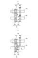
図3は、メイン軸5aに伝達されたトルクがドライブ軸5bに伝達されるメカニズムを説明するための概略図である。図3(a)および図3(b)においては、複数のギア5cのうちの2つのギア5c1,5c2が示され、複数のギア5dのうちの2つのギア5d1,5d2が示されている。
FIG. 3 is a schematic view for explaining a mechanism by which the torque transmitted to the
ギア5c1は、メイン軸5aの軸方向においては移動可能であるが、メイン軸5aの回転方向においてはメイン軸5aに固定されている。ギア5c2は、メイン軸5aの軸方向における移動が禁止された状態でメイン軸5aに回転可能に取り付けられている。
The gear 5c1 is movable in the axial direction of the
ギア5d1は、ドライブ軸5bの軸方向における移動が禁止された状態でドライブ軸5bに回転可能に取り付けられている。ギア5c1とギア5d1とが噛み合っている場合には、メイン軸5aが回転することによりギア5d1が回転する。
The gear 5d1 is rotatably attached to the
ギア5d2は、ドライブ軸5bの軸方向においては移動可能であるが、ドライブ軸5bの回転方向においてはドライブ軸5bに固定されている。そのため、ドライブ軸5bは、ギア5d2が回転することにより回転する。
The gear 5d2 is movable in the axial direction of the
図3(a)に示すように、ギア5d2がギア5d1から離間している場合には、ギア5d1は、ドライブ軸5bの回転方向においてドライブ軸5bに固定されていない。この場合、メイン軸5aが回転することにより、ギア5d1がメイン軸5aの回転に連動して回転するが、ドライブ軸5bはメイン軸5aの回転に連動することなく回転するかまたは停止する。すなわち、変速機5はエンジン107と後輪115との間でトルクを伝達しない。
As shown in FIG. 3A, when the gear 5d2 is separated from the gear 5d1, the gear 5d1 is not fixed to the
一方、図3(b)に示すように、ギア5d2がギア5d1に近づくように軸方向に移動する。これにより、ギア5d2の側面に設けられた凸状のドグ5fが、ギア5d1の側面に設けられた凹状のドグ穴(図示せず)に嵌め込まれると、ギア5d1とギア5d2とが固定される。この場合、メイン軸5aが回転することにより、ギア5d1とともにギア5d2がメイン軸5aの回転に連動して回転する。それにより、ドライブ軸5bがギア5d2とともにメイン軸5aの回転に連動して回転する。
On the other hand, as shown in FIG. 3B, the gear 5d2 moves in the axial direction so as to approach the gear 5d1. Thus, when the
なお、図3(a)の状態から、ギア5c1をギア5c2に近接させ、ギア5c1とギア5c2とを固定した場合には、ギア5c2はギア5c1とともに回転する。この場合、ギア5d2は、メイン軸5aおよびギア5c2の回転に連動して回転する。それにより、ドライブ軸5bがギア5d2とともにメイン軸5aの回転に連動して回転する。以下、ギア5c1,5d2のように、メイン軸5aまたはドライブ軸5b上を軸方向に移動するギアをスライドギアと称する。また、ギア5c2,5d1のように、メイン軸5aまたはドライブ軸5bの軸方向における移動が禁止されたギアをフィックスギアと称する。
When the gear 5c1 is moved close to the gear 5c2 and the gear 5c1 and the gear 5c2 are fixed from the state of FIG. 3A, the gear 5c2 rotates with the gear 5c1. In this case, the gear 5d2 rotates in conjunction with the rotation of the
このように、変速機5においては、1または複数のスライドギアを移動させ、1または複数のスライドギアと1または複数のフィックスギアとの組み合わせを変更することにより、メイン軸5aからドライブ軸5bへのトルクの伝達経路を変更することができる。それにより、メイン軸5aの回転速度に対してドライブ軸5bの回転速度を相対的に変更することができる。
As described above, in the transmission 5, the
変速機5において、1または複数のスライドギアを移動させるために、図2のシフト機構7が用いられる。図2に示すように、シフト機構7は、シフトペダル210、ペダルアーム211、第1のリンク機構220、シフト軸250、第2のリンク機構260、ストッパープレート300、シフトカム7bおよびシフトフォークc1〜c3を含む。
In the transmission 5, the shift mechanism 7 of FIG. 2 is used to move one or more slide gears. As shown in FIG. 2, the shift mechanism 7 includes a
後述するように、運転者はシフトペダル210を押し下げるかまたは押し上げる。この場合、図2に太い矢印で示すように、シフトペダル210に加わる荷重は、ペダルアーム211および第1のリンク機構220を通してシフト軸250に伝達される。これにより、シフト軸250が回転する。さらに、シフト軸250において発生するトルクは、第2のリンク機構260を通してシフトカム7bに伝達される。それにより、シフトカム7bが回転する。
As described below, the driver depresses or pushes up the
シフトカム7bには、カム溝d1〜d3が形成されている。シフトフォークc1〜c3は、摺動ピンe1〜e3によりカム溝d1〜d3にそれぞれ連結される。シフトカム7bの一端には、ストッパープレート300が取り付けられる。さらに、シフトカム7bの一端部近傍には、ストッパープレート300に近接してシフトカムセンサSE4が設けられる。エンジン107の作動時には、シフトカムセンサSE4により検出されたシフトカム7bの回転角度がECU50に出力される。
Cam grooves d1 to d3 are formed in the
運転者によるシフトぺダル210の操作によりシフトカム7bが回転すると、シフトフォークc1〜c3に連結される摺動ピンe1〜e3が各カム溝d1〜d3内を移動する。この場合、シフトフォークc1〜c3のいずれかがシフトカム7bの軸方向に移動し、1または複数のスライドギアが移動される。
When the
本例の変速機5は、ニュートラルポジションおよび1〜6速のギアポジションを有する。シフトカム7b(図2)が一方向に回転する場合、変速機5のギアポジションが1速、2速、3速、4速、5速および6速の順に切り替えられる。それにより、変速機5のギア比が順に高くなる(シフトアップ)。一方、シフトカム7b(図2)が逆方向に回転すると、変速機5のギアポジションが6速、5速、4速、3速、2速および1速の順に切り替えられる。それにより、変速機5のギア比が順に低くなる(シフトダウン)。
The transmission 5 of this example has a neutral position and gear positions of 1 to 6 gears. When the
ここで、運転者は、図1のクラッチレバー105aを操作することなく変速機5のギア比を切り替える、いわゆるクラッチレスシフトの意図を持ってシフトペダル210を操作する場合がある。以下の説明では、運転者が変速機5のギア比を切り替える意図を持って行うシフトぺダル210の操作をシフト操作と呼ぶ。本実施の形態では、シフト操作が行われたか否かが図2の荷重センサSE5からの出力信号に基づいて判定される。シフト操作が行われたか否かの判定方法の詳細は後述する。クラッチレバー105aが操作されることなくシフト操作が行われた場合、変速機5のギア比を切り替えるためのエンジン107の出力調整が適宜行われる。
Here, the driver may operate the
なお、シフト操作が行われたか否かの判定は、クラッチ3が接続状態にあるときに行われる。クラッチ3が接続状態にあるか否かは、例えば上記のクラッチセンサの検出値が予め定められた値を超えたか否かに基づいて判定することができる。 The determination as to whether or not the shift operation has been performed is performed when the clutch 3 is in the connected state. Whether or not the clutch 3 is in the connected state can be determined based on, for example, whether or not the detection value of the above-mentioned clutch sensor has exceeded a predetermined value.
[3]運転者によるシフトペダルの操作例と荷重センサによる荷重の検出
図4は、図1の第1のリンク機構220、シフトペダル210およびそれらの周辺部材を示す自動二輪車100の左側面図である。図4に示すように、自動二輪車100の左側面においては、前後方向に延びるようにペダルアーム211が設けられている。シフトペダル210は、ペダルアーム211の後端に取り付けられる。
[3] Example of operation of shift pedal by driver and detection of load by load sensor FIG. 4 is a left side view of the
ペダルアーム211のうち、中央部よりもやや前端に近い部分に取付部212が設けられている。ペダルアーム211の取付部212は、本体フレーム101(図1)から左方へ水平に延びる図示しない支持軸に回転可能に支持される。
An
ペダルアーム211の上方にシフト軸250が配置されている。ペダルアーム211とシフト軸250とを接続するように第1のリンク機構220が設けられる。具体的には、第1のリンク機構220は、第1のリンク軸221および第2のリンク軸222を含む。第2のリンク軸222の一端は、当該第2のリンク軸222がシフト軸250とともに回転可能となるようにかつシフト軸250から車両前方に延びるように、シフト軸250に固定される。第1のリンク軸221の一端はペダルアーム211の前端に回転可能に接続されている。第1のリンク軸221の他端は第2のリンク軸222の他端に回転可能に接続されている。
A
第1のリンク軸221の略中央部に荷重センサSE5が設けられている。荷重センサSE5は例えば弾性式(歪ゲージ式、静電容量式等)または磁歪式のロードセルからなり、第1のリンク軸221に加えられた引張荷重および圧縮荷重を検出可能に構成される。また、本例の荷重センサSE5は、シフトペダル210に荷重が加えられた場合に加えられた荷重に対応する検出値(電圧値)が出力されない不感帯領域を有する。荷重センサSE5の不感帯領域に対応する荷重を不感帯荷重と呼ぶ。シフトペダル210に加えられた荷重が不感帯荷重である場合、荷重センサSE5による荷重の検出値は0となる。
A load sensor SE5 is provided substantially at the center of the
運転者は、バックステップ120に左足を乗せた状態で、バックステップ120を支点としてシフトペダル210を押し下げまたは押し上げることによりシフトペダル210を操作する。
The driver operates the
図2のシフト機構7には、リターン式の変速方式が適用される。そのシフト機構7においては、シフトペダル210が押し上げられることにより、1速から6速までのシフトアップのための動作が行われる。また、シフトペダル210が押し下げられることにより、ニュートラルポジションから1速へギアポジションを切り替えるための動作または6速から1速までのシフトダウンのための動作が行われる。
A return type transmission system is applied to the shift mechanism 7 of FIG. In the shift mechanism 7, the
ここで、図4に太い一点鎖線の矢印SU1で示すように、運転者の左足FLによりシフトペダル210が押し上げられると、ペダルアーム211が反時計回りに回転する。これにより、太い一点鎖線の矢印SU2で示すように、第1のリンク軸221の一端(下端)が下方へ引き下げられる。また、太い一点鎖線の矢印SU3で示すように、第2のリンク軸222がシフト軸250を中心として反時計回りに回転する。このとき、第1のリンク軸221には引張荷重が加わる。引張荷重は荷重センサSE5により検出され、図2のECU50に出力される。なお、荷重センサSE5においては、引張荷重の検出値(電圧値)は0または正の値となる。
Here, as shown by a thick dashed-dotted arrow SU1 in FIG. 4, when the
一方、図4に太い点線の矢印SD1で示すように、運転者の左足FLによりシフトペダル210が押し下げられると、ペダルアーム211が時計回りに回転する。これにより、太い点線の矢印SD2で示すように、第1のリンク軸221の一端(下端)が上方へ押し上げられる。また、太い点線の矢印SD3で示すように、第2のリンク軸222がシフト軸250を中心として時計回りに回転する。このとき、第1のリンク軸221には圧縮荷重が加わる。圧縮荷重は荷重センサSE5により検出され、図2のECU50に出力される。なお、荷重センサSE5においては、圧縮荷重の検出値(電圧値)は0または負の値となる。
On the other hand, as shown by the thick dotted arrow SD1 in FIG. 4, when the
[4]シフト操作が行われたか否かの判定方法
以下の説明では、運転者が変速機5のギア比を切り替える意図を持たずに不感帯荷重を超える荷重をシフトペダル210に加える操作を非シフト操作と呼ぶ。非シフト操作は、例えば熟練していない運転者またはレースで緊張状態にある運転者等がシフトペダル210上で左足を無意識に踏み込む操作に相当する。あるいは、非シフト操作は、クラッチレスシフトのためのエンジンの出力調整機能を有しない鞍乗型車両に慣れた運転者、またはクラッチレスシフトの知識を有しない運転者が、変速機5のギア比を切り替える意図を持たずにシフトペダル210上で左足を踏み込む操作に相当する。
[4] Method of Determining Whether Shift Operation is Performed In the following description, the driver does not have an intention to switch the gear ratio of the transmission 5 and does not shift the operation of applying a load exceeding the dead zone load to the
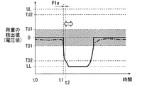
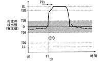
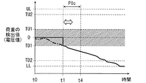
図5はシフトダウンのためのシフト操作時の荷重センサSE5の出力信号の一例を示す図であり、図6はシフトアップのためのシフト操作時の荷重センサSE5の出力信号の一例を示す図であり、図7は非シフト操作時の荷重センサSE5の出力信号の一例を示す図である。 FIG. 5 is a view showing an example of an output signal of the load sensor SE5 at the time of shift operation for downshift, and FIG. 6 is a view showing an example of an output signal of the load sensor SE5 at the time of shift operation for shift up. FIG. 7 is a view showing an example of the output signal of the load sensor SE5 at the time of non-shift operation.
図5〜図7では、縦軸が荷重センサSE5による荷重の検出値(電圧値)を示し、横軸が時間を示す。また、荷重センサSE5の検出上限値および検出下限値がそれぞれ符号UL,LLで示され、荷重センサSE5の不感帯領域がハッチングで示される。さらに、荷重センサSE5の出力信号の波形が太い実線で示されるとともに、不感帯領域がないと仮定した場合に出力されるべき荷重センサSE5の出力信号の波形が太い一点鎖線で示される。 In FIGS. 5 to 7, the vertical axis indicates the load detection value (voltage value) by the load sensor SE5, and the horizontal axis indicates time. Further, the detection upper limit value and the detection lower limit value of the load sensor SE5 are respectively indicated by reference symbols UL and LL, and the dead zone of the load sensor SE5 is indicated by hatching. Furthermore, the waveform of the output signal of the load sensor SE5 is indicated by a thick solid line, and the waveform of the output signal of the load sensor SE5 to be output when it is assumed that there is no dead zone is indicated by a thick dashed line.
図5の例では、時点t0から時点t1にかけて、太い一点鎖線に示されるように、出力されるべき検出値が不感帯領域内にある。そのため、荷重の検出値は0に維持される。時点t1で運転者がシフトダウンのためのシフト操作を開始する。この場合、シフトペダル210が押し下げられることにより、シフトペダル210に急激に大きな圧縮荷重が加えられる。それにより、荷重の検出値が短時間(例えば、100ms以下)で0から検出下限値LLまで到達する。その後、運転者は、シフトペダル210が一定量下方に移動したときにシフト操作を終了する。それにより、荷重の検出値が0に戻る。
In the example of FIG. 5, from the time point t0 to the time point t1, as indicated by the thick dashed-dotted line, the detected value to be output is in the dead zone region. Therefore, the detected load value is maintained at zero. At time t1, the driver starts a shift operation for downshifting. In this case, pressing the
図6の例においても、図5の例と同様に、時点t0から時点t1にかけて、荷重の検出値は0に維持される。時点t1で運転者がシフトアップのためのシフト操作を開始する。この場合、シフトペダル210が押し上げられることにより、シフトペダル210に急激に大きな引張荷重が加えられる。それにより、荷重の検出値が短時間(例えば、100ms以下)で0から検出上限値ULまで到達する。その後、運転者は、シフトペダル210が一定量上方に移動したときにシフト操作を終了する。それにより、荷重の検出値が0に戻る。
Also in the example of FIG. 6, as in the example of FIG. 5, the detected load value is maintained at 0 from time point t0 to time point t1. At time t1, the driver starts the shift operation for shift up. In this case, as the
図7の例においても、図5の例と同様に、時点t0から時点t1にかけて、荷重の検出値は0に維持される。時点t1で運転者により非シフト操作が開始される。この場合、時点t1で、圧縮荷重が不感帯領域に対応する荷重を超えることにより、荷重の検出値が0から負の値に変化する。このとき、非シフト操作においては、運転者は、変速機5のギア比を切り替える意図を持たないので、シフトペダル210を積極的に移動させるような操作を行わない。したがって、シフトペダル210に急激に大きな荷重が加えられることはない。しかしながら、非シフト操作中の運転者は、自己がどの程度の荷重をシフトペダル210に加えているかを全く認識していない。あるいは、非シフト操作中の運転者は、シフトペダル210を踏み込んでも図1のクラッチレバー105aおよびアクセルグリップのうち少なくとも一方を操作しない限りギア比は切り替えられないと考えている。そのため、シフトペダル210には、比較的大きな荷重が緩やかに加えられる可能性が高い。したがって、運転者によるシフトペダル210の操作がシフト操作であるかまたは非シフト操作であるかを、シフトペダル210に加わる荷重があるしきい値を超えたか否かのみで判定することは難しい。本例では、時点t1の経過後、荷重の検出値は、不感帯領域の下方の領域で比較的長い時間(例えば、1000ms程度)をかけて検出下限値LLに向かって緩やかに変化している。
Also in the example of FIG. 7, as in the example of FIG. 5, the detected load value is maintained at 0 from time point t0 to time point t1. At time t1, the driver starts the non-shifting operation. In this case, when the compression load exceeds the load corresponding to the dead zone at time t1, the detected load value changes from 0 to a negative value. At this time, in the non-shifting operation, since the driver does not have an intention to switch the gear ratio of the transmission 5, the driver does not positively move the
上記のように、運転者は、シフト操作を行う場合、シフトペダル210に比較的短時間で比較的大きな荷重を加える傾向がある。一方、運転者は、非シフト操作を行う場合、シフトペダル210に緩やかに荷重を加える傾向がある。本実施の形態では、これらの傾向を考慮した上で、運転者の意図によるシフト操作が行われたか否かの判定が以下のようにして行われる。
As described above, when the driver performs a shift operation, the driver tends to apply a relatively large load to the
まず、図5〜図7の縦軸に示されるように、図2のECU50に、荷重センサSE5により検出される荷重について、第1のシフトダウンしきい値TD1、第2のシフトダウンしきい値TD2、第1のシフトアップしきい値TU1および第2のシフトアップしきい値TU2が予め設定される。また、図5〜図7に白抜きの矢印で示されるように、所定長さの基準時間が予め設定される。
First, as shown by the vertical axes in FIGS. 5 to 7, the
第1のシフトダウンしきい値TD1および第2のシフトダウンしきい値TD2は負の値である。また、第2のシフトダウンしきい値TD2の絶対値は第1のシフトダウンしきい値TD1の絶対値よりも大きくかつ検出下限値LLの絶対値よりも小さい。さらに、第1のシフトダウンしきい値TD1は、不感帯領域の最小値以下となるように設定される。なお、本例の第1のシフトダウンしきい値TD1は、不感帯領域の最小値に設定されている。 The first downshift threshold TD1 and the second downshift threshold TD2 are negative values. The absolute value of the second downshift threshold TD2 is larger than the absolute value of the first downshift threshold TD1 and smaller than the absolute value of the lower detection limit LL. Furthermore, the first shift down threshold value TD1 is set to be equal to or less than the minimum value of the dead zone region. The first shift down threshold value TD1 in this example is set to the minimum value of the dead zone.
第1のシフトアップしきい値TU1および第2のシフトアップしきい値TU2は正の値である。また、第2のシフトアップしきい値TU2の絶対値は第1のシフトアップしきい値TU1の絶対値よりも大きくかつ検出上限値ULの絶対値よりも小さい。さらに、第1のシフトアップしきい値TU1は、不感帯領域の最大値以上となるように設定される。なお、本例の第1のシフトアップしきい値TU1は、不感帯領域の最大値に設定されている。 The first shift up threshold TU1 and the second shift up threshold TU2 are positive values. In addition, the absolute value of the second shift-up threshold TU2 is larger than the absolute value of the first shift-up threshold TU1 and smaller than the absolute value of the detection upper limit value UL. Further, the first shift-up threshold TU1 is set to be equal to or greater than the maximum value of the dead zone. The first shift up threshold value TU1 in this example is set to the maximum value of the dead zone.
基準時間は、運転者が変速機5のギア比を切り替える意図を持ってシフトペダル210を操作するために通常必要とされる時間を考慮して、例えば100msよりも長く200ms以下に定められる。
The reference time is set to, for example, more than 100 ms and 200 ms or less in consideration of the time normally required for the driver to operate the
シフト操作が行われたか否かの判定時には、まず荷重の検出値が第1のシフトダウンしきい値TD1よりも低くなったか否か、または荷重の検出値が第1のシフトアップしきい値TU1よりも高くなったか否かが判定される。すなわち、荷重の検出値が第1のシフトダウンしきい値TD1または第1のシフトアップしきい値TU1を超えたか否かが判定される。 When determining whether or not the shift operation has been performed, first, whether or not the detected load value is lower than the first downshift threshold value TD1, or the detected load value is the first shiftup threshold value TU1. It is determined whether it has become higher than that. That is, it is determined whether the detected load value exceeds the first downshift threshold value TD1 or the first upshift threshold value TU1.
荷重の検出値が第1のシフトダウンしきい値TD1を超えた場合には、その時点から荷重の検出値が第2のシフトダウンしきい値TD2よりも低くなるまでの時間が第1の操作時間として計測される。すなわち、荷重の検出値(絶対値)が第1のシフトダウンしきい値TD1(絶対値)を超えてから第2のシフトダウンしきい値TD2(絶対値)を超えるまでの時間が第1の操作時間として計測される。また、計測された第1の操作時間が予め設定された基準時間以下であるか否かが判定される。そこで、第1の操作時間が基準時間以下である場合には、運転者によるシフトペダル210の操作が、シフトダウンのためのシフト操作であると判定される。一方、第1の操作時間が基準時間よりも長い場合には、運転者によるシフトペダル210の操作が、シフト操作ではなく、非シフト操作であると判定される。
If the detected load value exceeds the first downshift threshold value TD1, the time from when the detected load value becomes lower than the second downshift threshold value TD2 is the first operation It is measured as time. That is, the time from when the detected load value (absolute value) exceeds the first shift down threshold value TD1 (absolute value) to when it exceeds the second shift down threshold value TD2 (absolute value) is the first It is measured as the operation time. Further, it is determined whether or not the measured first operation time is equal to or less than a preset reference time. Therefore, when the first operation time is equal to or less than the reference time, it is determined that the operation of the
図5の例では、時点t1で荷重の検出値が第1のシフトダウンしきい値TD1を超え、時点t2で荷重の検出値が第2のシフトダウンしきい値TD2を超えている。それにより、時点t1〜時点t2までの時間が第1の操作時間PIaとして計測される。計測された第1の操作時間PIaは、白抜きの矢印で示される基準時間以下である。それにより、運転者によるシフトペダル210の操作が、シフトダウンのためのシフト操作であると判定される。
In the example of FIG. 5, the detected load value exceeds the first downshift threshold TD1 at time t1, and the detected load value exceeds the second downshift threshold TD2 at time t2. Thereby, the time from time t1 to time t2 is measured as the first operation time PIa. The measured first operation time PIa is equal to or less than the reference time indicated by the white arrow. Thereby, it is determined that the driver's operation of the
図7の例では、時点t1で荷重の検出値が第1のシフトダウンしきい値TD1を超え、時点t4で荷重の検出値が第2のシフトダウンしきい値TD2を超えている。それにより、時点t1〜時点t4までの時間が第1の操作時間PIcとして計測される。計測された第1の操作時間PIcは、白抜きの矢印で示される基準時間よりも長い。それにより、運転者によるシフトペダル210の操作が、非シフト操作であると判定される。
In the example of FIG. 7, the detected load value exceeds the first downshift threshold value TD1 at time t1, and the detected load value exceeds the second downshift threshold value TD2 at time t4. Thereby, the time from time t1 to time t4 is measured as the first operation time PIc. The measured first operation time PIc is longer than the reference time indicated by the white arrow. Thus, it is determined that the driver's operation of the
荷重の検出値が第1のシフトアップしきい値TU1を超えた場合には、その時点から荷重の検出値が第2のシフトアップしきい値TU2よりも高くなるまでの時間が第2の操作時間として計測される。すなわち、荷重の検出値(絶対値)が第1のシフトアップしきい値TU1(絶対値)を超えてから第2のシフトアップしきい値TU2(絶対値)を超えるまでの時間が第2の操作時間として計測される。また、計測された第2の操作時間が予め定められた基準時間以下であるか否かが判定される。そこで、第2の操作時間が予め定められた基準時間以下である場合には、運転者によるシフトペダル210の操作が、シフトアップのためのシフト操作であると判定される。一方、第2の操作時間が予め定められた基準時間よりも長い場合には、運転者によるシフトペダル210の操作が、シフト操作ではなく、非シフト操作であると判定される。
If the detected load value exceeds the first shift-up threshold value TU1, the time until the detected load value becomes higher than the second shift-up threshold value TU2 from that time point is the second operation It is measured as time. That is, the time from when the detected load value (absolute value) exceeds the first shift-up threshold value TU1 (absolute value) to when it exceeds the second shift-up threshold value TU2 (absolute value) is the second It is measured as the operation time. Further, it is determined whether or not the measured second operation time is equal to or less than a predetermined reference time. Therefore, when the second operation time is equal to or less than a predetermined reference time, it is determined that the driver's operation of the
図6の例では、時点t1で荷重の検出値が第1のシフトアップしきい値TU1を超え、時点t3で荷重の検出値が第2のシフトアップしきい値TU2を超えている。それにより、時点t1〜時点t3までの時間が第2の操作時間PIbとして計測される。計測された第2の操作時間PIbは、白抜きの矢印で示される基準時間以下である。それにより、運転者によるシフトペダル210の操作が、シフトアップのためのシフト操作であると判定される。
In the example of FIG. 6, the detected load value exceeds the first shift-up threshold TU1 at time t1, and the detected load value exceeds the second shift-up threshold TU2 at time t3. Thereby, the time from time t1 to time t3 is measured as the second operation time PIb. The measured second operation time PIb is equal to or less than the reference time indicated by the white arrow. Thus, it is determined that the driver's operation of the
上記の判定方法によれば、非シフト操作がシフト操作であるという誤判定の発生が防止される。クラッチ3が接続された状態でシフト操作が行われたことが判定されると、後述するエンジン107の状態に応じてエンジン107の出力調整が行われる。それにより、変速機5のギア比が円滑に切り替えられる。
According to the above determination method, the occurrence of an erroneous determination that the non-shift operation is a shift operation is prevented. If it is determined that the shift operation has been performed with the clutch 3 connected, the output adjustment of the
なお、上記の判定方法においては、シフトダウンに対応する基準時間とシフトアップに対応する基準時間とが互いに異なるように個別に設定されてもよい。この場合、荷重の検出値が負の値である場合にシフトダウンに対応する基準時間を用いた判定を行い、荷重の検出値が正の値である場合にシフトアップに対応する基準時間を用いた判定を行う。それにより、シフト操作が行われたか否かをより適切に判定することが可能になる。 In the above determination method, the reference time corresponding to the downshift and the reference time corresponding to the upshift may be individually set so as to be different from each other. In this case, when the detected load value is a negative value, the determination is performed using the reference time corresponding to the downshift, and when the detected load value is a positive value, the reference time corresponding to the upshift is used. Make a decision. This makes it possible to more appropriately determine whether a shift operation has been performed.
なお、荷重センサSE5の出力信号はノイズ等の影響により乱れる場合がある。そこで、荷重の検出値が上記の各種しきい値を超えたか否かを正確に判定するために、基準時間よりも短い微小な判定時間が設定されてもよい。この場合、荷重の検出値が設定された判定時間の間連続して各種しきい値を超えた場合に、荷重の検出値が当該しきい値を超えたことが判定されてもよい。 The output signal of the load sensor SE5 may be disturbed by the influence of noise or the like. Therefore, a minute determination time shorter than the reference time may be set in order to accurately determine whether the detected load value exceeds the above-described various threshold values. In this case, it may be determined that the detected load value exceeds the threshold value when the detected load value exceeds various threshold values continuously during the set determination time.
例えば、荷重の検出値が第2のシフトアップしきい値TU2以下である状態から、判定時間の間第2のシフトアップしきい値TU2よりも高い状態が維持されたときに荷重の検出値が第2のシフトアップしきい値TU2を超えたことが判定されてもよい。また、荷重の検出値が第2のシフトダウンしきい値TD2以上である状態から、判定時間の間第2のシフトダウンしきい値TD2よりも低い状態が維持されたときに荷重の検出値が第2のシフトダウンしきい値TD2を超えたことが判定されてもよい。この場合、ノイズ等の影響による誤判定の発生が防止される。 For example, from the state where the detected load value is less than or equal to the second shift-up threshold TU2, the detected load value is maintained when the state higher than the second shift-up threshold TU2 is maintained for the determination time. It may be determined that the second shift up threshold TU2 has been exceeded. Also, from the state where the detected load value is equal to or higher than the second downshift threshold value TD2, when the state lower than the second downshift threshold value TD2 is maintained for the determination time, the detected load value is It may be determined that the second downshift threshold TD2 has been exceeded. In this case, the occurrence of an erroneous determination due to the influence of noise or the like is prevented.
[5]エンジン107の状態
ここで、エンジン107の作動中の状態について、変速機5におけるフィックスギアのドグ穴とスライドギアのドグとの関係とともに説明する。変速機5におけるフィックスギアのドグ穴とスライドギアのドグとの関係は、エンジン107の状態に応じて変化する。図8(a)〜(c)は、変速機5におけるフィックスギアのドグ穴とスライドギアのドグとの関係を示す図である。図8(a)〜(c)においては、スライドギア91におけるドグ92の形成部分およびフィックスギア93におけるドグ穴94の形成部分の断面図が模式的に示される。本例のスライドギア91およびフィックスギア93は、図3のギア5c1およびギア5c2にそれぞれ対応する。また、スライドギア91およびフィックスギア93の図8(a)〜(c)に示される部分は、太い矢印で示す方向に移動(回転)しているものとする。さらに、図2のクラッチ3は接続状態にあるものとする。
[5] State of
自動二輪車100が例えば上りの路面上で加速して走行している場合には、クランク軸2(図3)のトルクがドライブ軸5b(図3)に伝達される。具体的には、クランク軸2からメイン軸5aを通してスライドギア91に伝達されるトルクが、ドグ92によりフィックスギア93およびドライブ軸5bにさらに伝達される。この場合、図8(a)に示すように、ドグ92の移動方向における前方側の側面がドグ穴94の移動方向における前方側の側面に当接するとともに、ドグ92とドグ穴94との間に大きな噛み合い力が発生する。このように、クランク軸2から変速機5を通して後輪115にトルクが伝達される状態をエンジン107の駆動状態と呼ぶ。
For example, when the
一方、自動二輪車100が例えば下りの路面上でブレーキを用いることなく減速している場合には、ドライブ軸5bのトルクがクランク軸2に伝達される。具体的には、ドライブ軸5bからフィックスギア93に伝達されるトルクが、ドグ92によりスライドギア91およびメイン軸5aにさらに伝達される。この場合、図8(b)に示すように、ドグ92の移動方向における後方側の側面がドグ穴94の移動方向における後方側の側面に当接するとともに、ドグ92とドグ穴94との間に大きな噛み合い力が発生する。このように、後輪115から変速機5を通してクランク軸2にトルクが伝達される状態をエンジン107の被駆動状態と呼ぶ。エンジン107の被駆動状態は、いわゆるエンジンブレーキが作用しているときのエンジン107の状態である。
On the other hand, when the
エンジン107の状態が駆動状態および被駆動状態のいずれにも該当しない場合には、クランク軸2とドライブ軸5bとの間でトルクがほとんど伝達されない。この場合、ドグ92の回転速度とドグ穴94の回転速度とがほぼ等しくなることにより、ドグ92とドグ穴94との間に大きな噛み合い力が発生しない。それにより、図8(c)に白抜きの矢印で示すように、ドグ92がドグ穴94に対して回転方向およびメイン軸5aの軸方向に移動可能となる。このように、クランク軸2と後輪115との間でトルクが伝達されない状態をエンジン107の境界状態と呼ぶ。エンジン107の出力調整は、駆動状態または被駆動状態にあるエンジン107を境界状態に近づけるために行われる。
When the state of the
[6]エンジン107の状態の判定方法
本実施の形態に係る自動二輪車100においては、エンジン107の出力調整を行うか否かが、シフト操作の種類とエンジン107の状態との組み合わせに応じて決定される。
[6] Method of Determining the State of
具体的には、シフトダウンのためのシフト操作が行われた場合、シフトダウンのためのエンジン107の出力調整は、エンジン107が被駆動状態にあるときに行われ、エンジン107が駆動状態および境界状態にあるときに行われない。エンジン107が駆動状態にあるときに出力調整が行われないことにより、シフトダウン直後における駆動状態から被駆動状態への急激な切り替わりの発生が低減されるので、変速機5に過剰な負荷が加わることが低減される。したがって、変速機5の長寿命化が実現される。また、シフト操作が行われた時点でエンジン107が境界状態にあるときには、運転者がクラッチレスシフトの意図を持ってアクセル開度を調整している可能性が高い。したがって、エンジン107が境界状態にあるときに出力調整が行われないことにより、運転者の技能によるギア比の切り替えが可能となる。
Specifically, when a shift operation for downshifting is performed, the output adjustment of the
また、シフトアップのためのシフト操作が行われた場合、シフトアップのためのエンジン107の出力調整は、エンジン107が駆動状態にあるときに行われ、エンジン107が被駆動状態および境界状態にあるときに行われない。エンジン107が被駆動状態にあるときに出力調整が行われないことにより、エンジン107が被駆動状態にあるときに、自動二輪車100の速度が急激に上昇することが防止される。また、エンジン107が境界状態にあるときに出力調整が行われないことにより、運転者の技能によるギア比の切り替えが可能となる。
Also, when a shift operation for upshifting is performed, the output adjustment of the
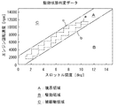
そこで、図2のECU50では、上記のようにシフト操作が行われたか否かの判定とともに、エンジン107が駆動状態、境界状態および被駆動状態のいずれの状態にあるかが判定される。具体的には、無負荷時のエンジン107の回転速度と後述するETV82(図10)のスロットル開度との関係を示すデータ(以下、駆動状態判定データと呼ぶ。)に基づいて、エンジン107が駆動状態、境界状態および被駆動状態のうちどの状態であるかが判定される。
Therefore, the
図9は、ECU50に記憶される駆動状態判定データの一例を示す図である。図9において、縦軸はエンジン107の回転速度を示し、横軸はETV82のスロットル開度を示す。
FIG. 9 is a view showing an example of drive state determination data stored in the
図9において、点線aは、ギア5c,5d(図2)が係合しないことにより変速機5がトルクを伝達しない状態にある場合のエンジン107の回転速度とスロットル開度との関係を示している。図9に示すように、変速機5がトルクを伝達しない状態にある場合、エンジン107の回転速度とスロットル開度との関係はヒステリシスループを形成する。なお、点線aに示す関係は、例えば、実験またはコンピュータを用いたシミュレーション等により導出することができる。
In FIG. 9, a dotted line a indicates the relationship between the rotational speed of the
本実施の形態においては、点線aに外接する2本の平行な直線の内側の帯状の領域(一点鎖線bと一点鎖線cとの間の領域)を境界領域Aと定義するとともに、一点鎖線bより下の領域を駆動領域Bと定義し、一点鎖線cより上の領域を被駆動領域Cと定義する。 In the present embodiment, a band-shaped area (area between the alternate long and short dash line b and the alternate long and short dash line c) inside two parallel straight lines circumscribing the dotted line a is defined as the boundary area A, and The lower region is defined as a drive region B, and the region above the alternate long and short dash line c is defined as a driven region C.
エンジン107の状態の判定時には、クランクセンサSE2の検出値に基づいてエンジン107の回転速度が算出される。算出された回転速度とスロットルセンサSE3の検出値とに基づいて、エンジン107とスロットル開度との関係が上記3つの領域のうちのどの領域に含まれているかが判定される。それにより、エンジン107が駆動状態、境界状態および被駆動状態のうちのどの状態であるかが判定される。
When determining the state of the
例えば、エンジン107の回転速度が6000rpmでスロットル開度が12degである状態は駆動領域Bに含まれる。この場合、エンジン107は駆動状態であると判定される。また、エンジン107の回転速度が6000rpmでスロットル開度が2degである状態は被駆動領域Cに含まれる。この場合、エンジン107は被駆動状態であると判定される。また、エンジン107の回転速度が6000rpmでスロットル開度が6degである状態は境界領域Aに含まれる。この場合、エンジン107は境界状態であると判定される。
For example, a state in which the rotational speed of the
[7]エンジン107およびその周辺部材と自動二輪車100の制御系
図10は、エンジン107およびその周辺部材と自動二輪車100の制御系の概略構成を示す図である。図10に示すように、エンジン107はシリンダ71を有し、シリンダ71内には、ピストン72が往復動可能に設けられる。また、シリンダ71内の上部には燃焼室73が形成される。燃焼室73は吸気ポート74および排気ポート75を介してエンジン107の外部に連通する。
[7] Control System of the
吸気ポート74の下流側の開口端74aに吸気弁76が開閉自在に設けられ、排気ポート75の上流側の開口端75aに排気弁77が開閉自在に設けられる。吸気弁76および排気弁77は、通常のカム機構により駆動される。燃焼室73の上部には、点火プラグ78が設けられる。
An
エンジン107には、吸気ポート74と連通するように吸気管79が取り付けられ、排気ポート75と連通するように排気管118が取り付けられる。吸気管79には、シリンダ71内に燃料を供給するためのインジェクタ108が設けられる。また、吸気管79内には、ETV82が設けられる。
An
エンジン107の作動時には、空気が吸気管79を通して吸気ポート74から燃焼室73内に吸入されるとともに、インジェクタ108により燃焼室73内に燃料が供給される。それにより、燃焼室73内で混合気が生成され、点火プラグ78により混合気に火花点火が行われる。燃焼室73内において混合気の燃焼により生じた既燃ガスは、排気ポート75から排気管118を通して排出される。
At the time of operation of the
ECU50においては、上記のようにCPUがROMに記憶された制御プログラムを実行する。それにより、記憶部51、荷重判定部52、時間計測部53、シフト判定部54、状態判定部55および出力制御部56の機能が実現される。なお、ECU50において実現される各機能部の構成の一部または全てが電子回路等のハードウェアにより実現されてもよい。
In the
記憶部51は、例えばROMおよびRAMの記憶領域の一部で構成され、第1のシフトダウンしきい値TD1、第2のシフトダウンしきい値TD2、第1のシフトアップしきい値TU1、第2のシフトアップしきい値TU2および基準時間を記憶する。また、記憶部51は、変速機5の複数のギアポジションにそれぞれ対応する複数の基準角度値を記憶するとともに、上記の駆動状態判定データを記憶する。
The
荷重判定部52は、荷重センサSE5からの出力信号に基づいて、荷重の検出値が第1のシフトダウンしきい値TD1を超えたか否かを判定するとともに、荷重の検出値が第2のシフトダウンしきい値TD2を超えたか否かを判定する。また、荷重判定部52は、荷重の検出値が第1のシフトダウンしきい値TD1を超えたか否かを判定するとともに、荷重の検出値が第2のシフトダウンしきい値TD2を超えたか否かを判定する。
The
時間計測部53は、荷重判定部52の判定結果に基づいて、荷重の検出値が第1のシフトダウンしきい値TD1を超えた時点から荷重の検出値が第2のシフトダウンしきい値TD2を超えた時点までの第1の操作時間を計測する。また、時間計測部53は、荷重判定部52の判定結果に基づいて、荷重の検出値が第1のシフトアップしきい値TU1を超えた時点から荷重の検出値が第2のシフトアップしきい値TU2を超えた時点までの第2の操作時間を計測する。
Based on the determination result of
シフト判定部54は、時間計測部53の計測結果に基づいて、運転者によるシフトペダル210の操作が運転者の意図によるシフト操作であるか否かを判定する。具体的には、シフト判定部54は、第1の操作時間が基準時間以下であるときにシフトダウンのためのシフト操作が行われたと判定し、第1の操作時間が基準時間よりも長いときに非シフト操作が行われたと判定する。また、シフト判定部54は、第2の操作時間が基準時間以下であるときにシフトアップのためのシフト操作が行われたと判定し、第2の操作時間が基準時間よりも長いときに非シフト操作が行われたと判定する。
The
さらに、シフト判定部54は、シフト操作が行われた場合に、シフトカムセンサSE4からの出力信号と記憶部51に記憶された複数の基準角度値とに基づいてギア比の切り替えが完了したか否かを判定する。
Furthermore, when the shift operation is performed,
状態判定部55は、クランクセンサSE2からの出力信号およびスロットルセンサSE3の出力信号と駆動状態判定データとに基づいて、エンジン107の状態を判定する。出力制御部56は、シフト操作が行われていない場合に、アクセルセンサSE1からの出力信号に基づいて、ETV82のスロットル開度を調整する。一方、出力制御部56は、クラッチレバー105aが操作されることなくシフト操作が行われた場合に、エンジン107の状態に応じてエンジン107の出力調整を行う。
The
なお、記憶部51には、上記の判定時間が記憶されてもよい。この場合、荷重判定部52は、荷重の検出値が判定時間の間連続して各種しきい値を超えた場合に、荷重の検出値が当該しきい値を超えたと判定する。
Note that the
[8]ECU50における制御動作
図11および図12は、ECU50における制御動作の一例を示すフローチャートである。以下に説明する制御動作は、停止状態にあるエンジン107が作動することにより開始され、作動状態にあるエンジン107が停止することにより終了する。
[8] Control Operation of the
制御動作が開始されると、出力制御部56は、通常時の制御処理として、アクセルセンサSE1により検出されたアクセル開度に応じてETV82のスロットル開度を調整する(ステップS501)。それにより、エンジン107の出力がアクセル開度に応じた値に調整される。
When the control operation is started, the
次に、荷重判定部52は、荷重の検出値が第1のシフトダウンしきい値TD1を超えたか否かを判定する(ステップS502)。荷重の検出値が第1のシフトダウンしきい値TD1を超えた場合、時間計測部53は、時間の計測を開始する(ステップS503)。
Next, the
その後、荷重判定部52は、荷重の検出値が第2のシフトダウンしきい値TD2を超えたか否かを判定する(ステップS504)。荷重の検出値が第2のシフトダウンしきい値TD2を超えていない場合、荷重判定部52は、直前のステップS503で時間の計測が開始された後、予め定められた計測制限時間が経過したか否かを判定する(ステップS505)。なお、計測制限時間は、基準時間よりも長くかつ数秒程度に設定される。
Thereafter, the
ステップS505において、計測が開始されてから計測制限時間が経過していない場合、荷重判定部52はステップS504の処理に戻る。一方、計測が開始されてから計測制限時間が経過した場合、出力制御部56はステップS501の処理に戻る。それにより、シフト操作が行われたか否かの判定が初期状態に戻される。このとき、時間計測部53は、時間の計測を終了する。
In step S505, when the measurement limit time has not elapsed since the measurement was started, the
ステップS504において、荷重の検出値が第2のシフトダウンしきい値TD2を超えた場合、時間計測部53は、時間の計測を終了し、計測の開始から終了までの時間を第1の操作時間とする(ステップS506)。
In step S504, when the detected load value exceeds the second downshift threshold value TD2, the
次に、シフト判定部54は、計測された第1の操作時間が基準時間以下であるか否かを判定する(ステップS507)。第1の操作時間が基準時間よりも長い場合、シフト判定部54はシフト操作が行われておらず、非シフト操作が行われていると判定する。そこで、出力制御部56はステップS501の処理に戻る。
Next, the
一方、第1の操作時間が基準時間以下である場合、シフト判定部54はシフトダウンのためのシフト操作が行われたと判定する。そこで、状態判定部55は、エンジン107が被駆動状態にあるか否かを判定する(ステップS508)。
On the other hand, when the first operation time is equal to or less than the reference time, the
ステップS508において、エンジン107が被駆動状態にある場合、出力制御部56は、シフトダウンのためのエンジン107の出力調整を開始する(ステップS509)。シフトダウンのためのエンジン107の出力調整では、例えばETV82のスロットル開度が増加される。それにより、エンジン107の出力が増加され、クランク軸2に発生するトルクが0に近づくように調整される。
In step S508, when the
なお、ステップS509の出力調整では、ETV82のスロットル開度を増加させる代わりに、インジェクタ108の燃料噴射量を増加させることにより、エンジン107の出力を増加させてもよい。あるいは、混合気の点火時期をずらすことによりエンジン107の出力を増加させてもよい。
In the output adjustment of step S509, the output of the
ステップS508でエンジン107が被駆動状態にない場合、出力制御部56はステップS501の処理に戻る。この場合、エンジン107の出力調整が行われない。
If the
ステップS509の処理後、シフト判定部54は、シフトカムセンサSE4の出力信号に基づいて変速機5におけるシフトダウンが完了したか否かを判定する(ステップS510)。シフト判定部54は、シフトダウンが完了するまでステップS510の処理を繰り返す。その後、シフトダウンが完了すると、出力制御部56は、エンジン107の出力調整を終了し(ステップS511)、ステップS501の処理に戻る。
After the process of step S509, the
上記のステップS502において、荷重の検出値が第1のシフトダウンしきい値TD1を超えていない場合、荷重判定部52は、荷重の検出値が第1のシフトアップしきい値TU1を超えたか否かを判定する(ステップS521)。荷重の検出値が第1のシフトアップしきい値TU1を超えた場合、時間計測部53は、時間の計測を開始する(ステップS522)。
In step S502 above, when the detected load value does not exceed the first downshift threshold value TD1, the
その後、荷重判定部52は、荷重の検出値が第2のシフトアップしきい値TU2を超えたか否かを判定する(ステップS523)。荷重の検出値が第2のシフトアップしきい値TU2を超えていない場合、荷重判定部52は、直前のステップS522で時間の計測が開始された後、予め定められた計測制限時間が経過したか否かを判定する(ステップS524)。
Thereafter, the
ステップS524において、計測が開始されてから計測制限時間が経過していない場合、荷重判定部52はステップS523の処理に戻る。一方、計測が開始されてから計測制限時間が経過した場合、出力制御部56はステップS501の処理に戻る。それにより、シフト操作が行われたか否かの判定が初期状態に戻される。このとき、時間計測部53は、時間の計測を終了する。
In step S524, when the measurement limit time has not elapsed since the measurement was started, the
ステップS523において、荷重の検出値が第2のシフトアップしきい値TU2を超えた場合、時間計測部53は、時間の計測を終了し、計測の開始から終了までの時間を第2の操作時間とする(ステップS525)。
In step S523, when the detected load value exceeds the second shift-up threshold value TU2, the
次に、シフト判定部54は、計測された第2の操作時間が基準時間以下であるか否かを判定する(ステップS526)。第2の操作時間が基準時間よりも長い場合、シフト判定部54はシフト操作が行われておらず、非シフト操作が行われていると判定する。そこで、出力制御部56はステップS501の処理に戻る。
Next, the
一方、第2の操作時間が基準時間以下である場合、シフト判定部54はシフトアップのためのシフト操作が行われたと判定する。そこで、状態判定部55は、エンジン107が駆動状態にあるか否かを判定する(ステップS527)。
On the other hand, when the second operation time is equal to or less than the reference time, the
ステップS527において、エンジン107が駆動状態にある場合、出力制御部56は、シフトアップのためのエンジン107の出力調整を開始する(ステップS528)。シフトアップのためのエンジン107の出力調整では、例えば点火プラグ78による混合気の点火が停止される。それにより、エンジン107の出力が低下され、クランク軸2に発生するトルクが0に近づくように調整される。
In step S527, when the
なお、ステップS528の出力調整では、混合気の点火を停止させる代わりに、ETV82のスロットル開度を減少させるかまたはインジェクタ108の燃料噴射量を減少させることにより、エンジン107の出力を低下させてもよい。あるいは、混合気の点火時期をずらすことによりエンジン107の出力を低下させてもよい。
In the output adjustment of step S528, instead of stopping the ignition of the air-fuel mixture, the output of the
ステップS527でエンジン107が駆動状態にない場合、出力制御部56はステップS501の処理に戻る。この場合、エンジン107の出力調整が行われない。
If the
ステップS528の処理後、シフト判定部54は、シフトカムセンサSE4の出力信号に基づいて変速機5におけるシフトアップが完了したか否かを判定する(ステップS529)。シフト判定部54は、シフトアップが完了するまでステップS529の処理を繰り返す。その後、シフトアップが完了すると、出力制御部56は、ステップS511の処理に進み、エンジン107の出力調整を終了し、ステップS501の処理に戻る。
After the process of step S528, the
[9]実施の形態の効果
(a)シフト操作時に、運転者は、シフトペダル210に比較的短時間で比較的大きな荷重を加える傾向がある。一方、非シフト操作時に、運転者は、シフトペダル210に比較的緩やかに荷重を加える傾向がある。これらの傾向に基づいて、上記の自動二輪車100においては、運転者の意図によるシフト操作が行われたか否かの判定が行われる。
[9] Effects of Embodiment (a) At the time of shift operation, the driver tends to apply a relatively large load to the
具体的には、荷重センサSE5による荷重の検出値が第1のシフトダウンしきい値TD1を超えた時点から第2のシフトダウンしきい値TD2を超えた時点までの時間が第1の操作時間として計測される。第1の操作時間が基準時間以下であるときに、運転者によるシフトペダル210の操作がシフトダウンのためのシフト操作であると判定される。一方、第1の操作時間が基準時間よりも長いときに、運転者によるシフトペダル210の操作が運転者の意図によらない非シフト操作であると判定される。
Specifically, the time from the time when the detected value of the load by the load sensor SE5 exceeds the first downshift threshold TD1 to the time when the second downshift threshold TD2 is exceeded is the first operation time It is measured as When the first operation time is equal to or less than the reference time, it is determined that the driver's operation of
また、荷重センサSE5による荷重の検出値が第1のシフトアップしきい値TU1を超えた時点から第2のシフトアップしきい値TU2を超えた時点までの時間が第2の操作時間として計測される。第2の操作時間が基準時間以下であるときに、運転者によるシフトペダル210の操作がシフトアップのためのシフト操作であると判定される。一方、第2の操作時間が基準時間よりも長いときに、運転者によるシフトペダル210の操作が運転者の意図によらない非シフト操作であると判定される。
Also, the time from the time when the detected value of the load by the load sensor SE5 exceeds the first shift up threshold TU1 to the time when the second shift up threshold TU2 is exceeded is measured as the second operation time Ru. When the second operation time is equal to or less than the reference time, it is determined that the operation of the
それにより、運転者が変速機5のギア比を切り替える意図を持たずにシフトペダル210を操作した場合に、当該操作がシフト操作であると誤って判定されることが防止される。したがって、運転者の意図によるシフト操作の有無が正確に判定されるので、変速機5のギア比を切り替えるためのエンジン107の出力調整を適切に行うことが可能となる。
Thereby, when the driver operates the
(b)上記の例では、第1のシフトダウンしきい値TD1は不感帯領域の最小値以下となるように設定されている。この場合、不感帯領域を有する荷重センサSE5が用いられる場合でも、荷重の検出値が第1のシフトダウンしきい値TD1を超えたか否かを正確に判定することができる。また、第1のシフトアップしきい値TU1は、不感帯領域の最大値以上となるように設定されている。この場合、不感帯領域を有する荷重センサSE5が用いられる場合でも、荷重の検出値が第1のシフトアップしきい値TU1を超えたか否かを正確に判定することができる。 (B) In the above example, the first downshift threshold value TD1 is set to be equal to or less than the minimum value of the dead zone. In this case, even when the load sensor SE5 having the dead zone is used, it can be accurately determined whether or not the detected load value exceeds the first downshift threshold value TD1. The first shift up threshold TU1 is set to be equal to or greater than the maximum value of the dead zone. In this case, even when the load sensor SE5 having the dead zone is used, it can be accurately determined whether the detected load value exceeds the first shift-up threshold value TU1.
それにより、不感帯領域を有しない高価な荷重センサを用いる必要がないので、荷重センサによるコストの増大が抑制される。 Thereby, since it is not necessary to use the expensive load sensor which does not have a dead zone area | region, the increase in the cost by a load sensor is suppressed.
[10]他の実施の形態
(a)上記実施の形態では、荷重センサSE5は、第1のリンク軸221に加えられる圧縮荷重および引張荷重を検出可能に構成されるが、本発明はこれに限定されない。荷重センサSE5は、圧縮荷重および引張荷重のうち一方のみを検出可能に構成されてもよい。
[10] Other Embodiments (a) In the above embodiment, the load sensor SE5 is configured to detect the compressive load and the tensile load applied to the
この場合、シフトアップおよびシフトダウンのうち一方のためのシフト操作のみが判定対象となる。それにより、図11および図12の制御動作においては、ステップS503〜S510の処理、およびステップS522〜S529の処理のうち一方の処理を行う必要がなくなる。 In this case, only the shift operation for one of upshift and downshift is to be determined. Thus, in the control operations of FIGS. 11 and 12, it is not necessary to perform one of the processing of steps S503 to S510 and the processing of steps S522 to S529.
(b)上記実施の形態では、シフトペダル210が押し上げられることによりシフトアップが行われ、シフトペダル210が押し下げられることによりシフトダウンが行われるが、本発明はこれに限定されない。
(B) In the above embodiment, upshifting is performed by pushing up the
シフト機構7は、シフトペダル210が押し下げられることによりシフトアップが行われ、シフトペダル210が押し上げられることによりシフトダウンが行われるように構成されてもよい。この場合、第1および第2のシフトダウンしきい値TD1,TD2は正の値となり、第1および第2のシフトアップしきい値TU1,TU2は負の値となる。
The shift mechanism 7 may be configured to shift up by pressing the
(c)上記実施の形態では、エンジン107が駆動状態にある場合にはシフトダウンのためのエンジン107の出力調整が行われないが、本発明はこれに限定されない。
(C) In the above embodiment, the output adjustment of the
エンジン107が駆動状態にある場合であっても、シフトダウンのためのシフト操作に基づいてエンジン107の出力調整が行われてもよい。この場合、エンジン107が境界状態にある場合にのみエンジン107の出力調整が行われなくてもよい。
Even when the
また、上記実施の形態では、エンジン107が被駆動状態にある場合にはシフトアップのためのエンジン107の出力調整が行われないが、本発明はこれに限定されない。エンジン107が被駆動状態にある場合であっても、シフトアップのためのシフト操作に基づいてエンジン107の出力調整が行われてもよい。この場合、エンジン107が境界状態にある場合にのみエンジン107の出力調整が行われなくてもよい。
In the above embodiment, when the
なお、エンジン107の状態によらず、シフトダウンおよびシフトアップのためのエンジン107の出力調整が可能となる場合には図10の状態判定部55はなくてもよい。
If the output adjustment of the
(d)上記実施の形態では、荷重センサSE5は不感帯領域を有するが、荷重センサSE5は不感帯領域を有さなくてもよい。 (D) In the above-mentioned embodiment, although load sensor SE5 has a dead zone area, load sensor SE5 does not need to have a dead zone area.
(e)上記実施の形態では、荷重センサSE5が第1のリンク軸221に設けられるが、本発明はこれに限定されない。荷重センサSE5は、運転者がシフトペダル210に加える荷重を直接的または間接的に検出することができればよい。したがって、荷重センサSE5は、第1のリンク軸221に代えて、第2のリンク軸222に設けられてもよいし、シフトペダル210に設けられてもよい。
(E) In the above-mentioned embodiment, although load sensor SE5 is provided in the
(f)上記実施の形態は、本発明を上記実施の形態は、本発明を自動二輪車に適用した例であるが、これに限らず、自動四輪車、自動三輪車もしくはATV(All Terrain Vehicle;不整地走行車両)等の他の鞍乗型車両に本発明を適用してもよい。 (F) The above embodiment is an example in which the present invention is applied to a motorcycle according to the above embodiment. However, the present invention is not limited to this. A four-wheeled vehicle, a three-wheeled motor vehicle or an ATV (All Terrain Vehicle; The present invention may be applied to other straddle-type vehicles such as rough terrain vehicles).
[11]参考形態
参考形態に係る自動二輪車は、以下の点を除いて上記実施の形態に係る自動二輪車100と同じ構成を有する。
[11] Reference Embodiment A motorcycle according to a reference embodiment has the same configuration as the
参考形態に係る自動二輪車においては、シフトダウンのためのシフト操作が行われかつエンジン107が被駆動状態にある場合に、ECU50の出力制御部56が、エンジン107の出力を調整する代わりに、クラッチ3を一時的に切断する。また、シフトアップのためのシフト操作が行われかつエンジン107が駆動状態にある場合に、ECU50の出力制御部56が、エンジン107の出力を調整する代わりに、クラッチ3を一時的に切断する。これらの場合、クラッチ3が自動的に切断されることにより変速機5のギア比の切り替えが円滑に行われる。
In the motorcycle according to the reference embodiment, when the shift operation for downshift is performed and
[12]実施の形態の各部と請求項の各構成要素との対応
以下、請求項の各構成要素と実施の形態の各構成要素との対応の例について説明するが、本発明は下記の例に限定されない。
[12] Correspondence between each component of the embodiment and each component of the claim Hereinafter, an example of the correspondence between each component of the claim and each component of the embodiment will be described, but the present invention is not limited to the following example It is not limited to.
上記の実施の形態においては、自動二輪車100が鞍乗型車両の例であり、エンジン107がエンジンの例であり、後輪115が駆動輪の例であり、変速機5が変速機の例であり、シフトペダル210が操作部材およびシフトペダルの例であり、荷重センサSE5が荷重センサの例であり、第1のシフトダウンしきい値TD1および第1のシフトアップしきい値TU1が第1のしきい値の例であり、第2のシフトダウンしきい値TD2および第2のシフトアップしきい値TU2が第2のしきい値の例である。
In the above embodiment, the
また、荷重判定部52と時間計測部53とを含む構成が計測部の例であり、基準時間が第1の時間、シフトダウン基準時間およびシフトアップ基準時間の例であり、シフト判定部54がシフト判定部の例であり、出力制御部56が制御部の例であり、荷重判定部52が荷重判定部の例であり、判定時間が第2の時間の例である。
The configuration including the
また、図4に太い点線の矢印SD1で示されるようにシフトペダル210が押し下げられる方向が第1の方向の例であり、図4に太い一点鎖線の矢印SU1で示されるようにシフトペダル210が押し上げられる方向が第2の方向の例であり、圧縮荷重が第1の荷重の例であり、引張荷重が第2の荷重の例である。
Also, as shown by the thick dotted arrow SD1 in FIG. 4, the direction in which the
請求項の各構成要素として、請求項に記載されている構成または機能を有する他の種々の構成要素を用いることもできる。 Various other components having the configurations or functions described in the claims can also be used as the components in the claims.
2…クランク軸,3…クラッチ,5…変速機,5a…メイン軸,5b…ドライブ軸,5c,5d,5c1,5c2,5d1,5d2…ギア,5e…後輪ドライブスプロケット,5f,92…ドグ,7…シフト機構,7b…シフトカム,50…ECU,51…記憶部,52…荷重判定部,53…時間計測部,54…シフト判定部,55…状態判定部,56…出力制御部,71…シリンダ,72…ピストン,73…燃焼室,74…吸気ポート,74a,75a…開口端,75…排気ポート,76…吸気弁,77…排気弁,78…点火プラグ,79…吸気管,82…ETV,91…スライドギア,92…ドグ,93…フィックスギア,94…ドグ穴,100…自動二輪車,101…本体フレーム,102…ヘッドパイプ,103…フロントフォーク,104…前輪,105…ハンドル,105a…クラッチレバー,107…エンジン,108…インジェクタ,109…クランクケース,110…ミッションケース,112…燃料タンク,113…シート,114…リアアーム,115…後輪,116…後輪ドリブンスプロケット,117…チェーン,118…排気管,120…バックステップ,210…シフトペダル,211…ペダルアーム,212…取付部,220…第1のリンク機構,221…第1のリンク軸,222…第2のリンク軸,250…シフト軸,260…第2のリンク機構,300…ストッパープレート,B…駆動領域,C…被駆動領域,c1〜c3…シフトフォーク,d1〜d3…カム溝,e1〜e3…摺動ピン,FL…左足,LL…検出下限値,PIa,PIc…第1の操作時間,PIb…第2の操作時間,SE1…アクセルセンサ,SE2…クランクセンサ,SE3…スロットルセンサ,SE4…シフトカムセンサ,SE5…荷重センサ,TD1…第1のシフトダウンしきい値,TD2…第2のシフトダウンしきい値,TU1…第1のシフトアップしきい値,TU2…第2のシフトアップしきい値,UL…検出上限値
DESCRIPTION OF
Claims (5)
駆動輪と、
前記エンジンにより発生されるトルクを前記駆動輪に伝達する変速機と、
前記変速機のギア比を切り替えるために運転者により操作される操作部材と、
運転者により前記操作部材に加えられた荷重を検出する荷重センサと、
前記荷重センサにより検出される荷重が第1のしきい値を超えた時点から前記第1のしきい値よりも大きい第2のしきい値を超えた時点までの時間を操作時間として計測する計測部と、
前記計測部により計測された操作時間が第1の時間以下であるときに運転者による前記操作部材の操作が前記変速機のギア比を切り替えるためのシフト操作であると判定し、前記計測部により計測された操作時間が前記第1の時間よりも長いときに運転者による前記操作部材の操作が前記シフト操作でないと判定するシフト判定部と、
前記シフト判定部により運転者による前記操作部材の操作が前記シフト操作であると判定された場合に、前記変速機のギア比を切り替えるためにエンジンの出力を調整する制御部とを備える、鞍乗型車両。 With the engine,
Drive wheels,
A transmission for transmitting torque generated by the engine to the drive wheels;
An operating member operated by a driver to switch a gear ratio of the transmission;
A load sensor for detecting a load applied to the operation member by a driver;
Measurement that measures the time from when the load detected by the load sensor exceeds a first threshold to when it exceeds a second threshold larger than the first threshold as the operation time Department,
When the operation time measured by the measurement unit is equal to or less than the first time, it is determined that the operation of the operation member by the driver is a shift operation for switching the gear ratio of the transmission, and the measurement unit A shift determination unit that determines that the operation of the operation member by the driver is not the shift operation when the measured operation time is longer than the first time;
A control unit for adjusting an output of an engine to switch a gear ratio of the transmission when the shift determination unit determines that the operation of the operation member by the driver is the shift operation; Type vehicle.
前記第1のしきい値の絶対値は、前記不感帯領域の最大値の絶対値以上である、請求項1記載の鞍乗型車両。 The load sensor has a dead zone region,
The straddle-type vehicle according to claim 1, wherein the absolute value of the first threshold is equal to or greater than the absolute value of the maximum value of the dead zone.
前記荷重判定部は、前記荷重センサにより検出された荷重が前記第1の時間よりも短い第2の時間連続して前記第2のしきい値を超えた場合に、前記荷重センサにより検出される荷重が前記第2のしきい値を超えたことを判定する、請求項1または2記載の鞍乗型車両。 The measurement unit includes a load determination unit that determines whether a load detected by the load sensor exceeds the second threshold value.
The load determination unit is detected by the load sensor when the load detected by the load sensor continuously exceeds the second threshold for a second period of time shorter than the first period of time. The straddle-type vehicle according to claim 1 or 2, wherein it is determined that a load exceeds the second threshold.
前記荷重センサは、前記第1の方向に加わる荷重を第1の荷重として検出可能であり、前記第2の方向に加わる荷重を第2の荷重として検出可能であり、
前記第1のしきい値は、第1のシフトダウンしきい値および第1のシフトアップしきい値を含み、
前記第2のしきい値は、第2のシフトダウンしきい値および第2のシフトアップしきい値を含み、
前記第1の時間は、シフトダウン基準時間およびシフトアップ基準時間を含み、
前記計測部は、前記荷重センサにより検出された前記第1の荷重が前記第1のシフトダウンしきい値を超えた時点から前記第2のシフトダウンしきい値を超えた時点までの時間を第1の操作時間として計測し、前記荷重センサにより検出された前記第2の荷重が前記第1のシフトアップしきい値を超えた時点から前記第2のシフトアップしきい値を超えた時点までの時間を第2の操作時間として計測し、
前記シフト判定部は、前記計測部により計測された第1の操作時間が前記シフトダウン基準時間以下であるときに運転者による前記操作部材の操作が前記シフトダウンのためのシフト操作であると判定し、前記計測部により計測された第1の操作時間が前記シフトダウン基準時間よりも長いときに運転者による前記操作部材の操作が前記シフトダウンのためのシフト操作でないと判定し、前記計測部により計測された第2の操作時間が前記シフトアップ基準時間以下であるときに運転者による前記操作部材の操作が前記シフトアップのためのシフト操作であると判定し、前記計測部により計測された第2の操作時間が前記シフトアップ基準時間よりも長いときに運転者による前記操作部材の操作が前記シフトアップのためのシフト操作でないと判定する、請求項1〜3のいずれか一項に記載の鞍乗型車両。 The operating member is configured to be operable by the driver in a first direction for downshifting the transmission, and is different from the first direction by the driver for upshifting the transmission. Configured to be operable in a second direction,
The load sensor can detect a load applied in the first direction as a first load, and can detect a load applied in the second direction as a second load.
The first threshold includes a first shift down threshold and a first shift up threshold.
The second threshold includes a second shift down threshold and a second shift up threshold.
The first time includes a downshift reference time and an upshift reference time,
The measurement unit is configured to calculate a time from a point in time when the first load detected by the load sensor exceeds the first shift down threshold to a point in time when the second load down threshold is exceeded. From the time when the second load detected by the load sensor exceeds the first shift-up threshold to the time when the second shift-up threshold is exceeded Measure the time as the second operation time,
The shift determination unit determines that the operation of the operation member by the driver is the shift operation for the downshift when the first operation time measured by the measurement unit is equal to or less than the downshift reference time. When the first operation time measured by the measurement unit is longer than the downshift reference time, it is determined that the operation of the operation member by the driver is not the shift operation for the downshift, and the measurement unit When it is determined that the operation of the operation member by the driver is the shift operation for the shift up when the second operation time measured by the second operation time is equal to or less than the shift up reference time, the measurement unit measures When the second operation time is longer than the shift-up reference time, the operation of the operating member by the driver is not the shift operation for the shift-up Determining, straddle-type vehicle according to any one of claims 1 to 3.
Priority Applications (2)
| Application Number | Priority Date | Filing Date | Title |
|---|---|---|---|
| JP2017235055A JP2019100511A (en) | 2017-12-07 | 2017-12-07 | Saddle-riding type vehicle |
| EP18190177.8A EP3495697B1 (en) | 2017-12-07 | 2018-08-22 | Straddled vehicle |
Applications Claiming Priority (1)
| Application Number | Priority Date | Filing Date | Title |
|---|---|---|---|
| JP2017235055A JP2019100511A (en) | 2017-12-07 | 2017-12-07 | Saddle-riding type vehicle |
Publications (1)
| Publication Number | Publication Date |
|---|---|
| JP2019100511A true JP2019100511A (en) | 2019-06-24 |
Family
ID=63363940
Family Applications (1)
| Application Number | Title | Priority Date | Filing Date |
|---|---|---|---|
| JP2017235055A Pending JP2019100511A (en) | 2017-12-07 | 2017-12-07 | Saddle-riding type vehicle |
Country Status (2)
| Country | Link |
|---|---|
| EP (1) | EP3495697B1 (en) |
| JP (1) | JP2019100511A (en) |
Cited By (1)
| Publication number | Priority date | Publication date | Assignee | Title |
|---|---|---|---|---|
| JP2025133193A (en) * | 2024-03-01 | 2025-09-11 | 本田技研工業株式会社 | Saddle-riding type vehicle |
Family Cites Families (6)
| Publication number | Priority date | Publication date | Assignee | Title |
|---|---|---|---|---|
| JP2813009B2 (en) * | 1989-10-23 | 1998-10-22 | 本田技研工業株式会社 | Transmission for vehicles |
| JPH09509730A (en) * | 1994-12-24 | 1997-09-30 | ルーク ゲトリーベ−ジステーメ ゲゼルシャフト ミット ベシュレンクテル ハフツング | Device and method for controlling an effective torque transmission system between a drive unit and a transmission |
| JP4762182B2 (en) | 2007-03-20 | 2011-08-31 | 川崎重工業株式会社 | Vehicle shift control device and vehicle equipped with the same |
| EP2080884A3 (en) * | 2008-01-16 | 2013-11-20 | Yamaha Hatsudoki Kabushiki Kaisha | Control system and saddle-straddling type vehicle including the same |
| JP6107621B2 (en) * | 2013-11-29 | 2017-04-05 | スズキ株式会社 | Motorcycle shift rod device |
| JP6731264B2 (en) * | 2016-03-18 | 2020-07-29 | 本田技研工業株式会社 | Shift control device |
-
2017
- 2017-12-07 JP JP2017235055A patent/JP2019100511A/en active Pending
-
2018
- 2018-08-22 EP EP18190177.8A patent/EP3495697B1/en active Active
Cited By (2)
| Publication number | Priority date | Publication date | Assignee | Title |
|---|---|---|---|---|
| JP2025133193A (en) * | 2024-03-01 | 2025-09-11 | 本田技研工業株式会社 | Saddle-riding type vehicle |
| JP7805384B2 (en) | 2024-03-01 | 2026-01-23 | 本田技研工業株式会社 | Saddle-type vehicle |
Also Published As
| Publication number | Publication date |
|---|---|
| EP3495697A1 (en) | 2019-06-12 |
| EP3495697B1 (en) | 2019-11-20 |
Similar Documents
| Publication | Publication Date | Title |
|---|---|---|
| JP5041974B2 (en) | Control system and vehicle | |
| US7846062B2 (en) | Control system and vehicle including the same | |
| US20080149409A1 (en) | Engine output adjustment system and vehicle including the same | |
| JP5238464B2 (en) | Control system and saddle riding type vehicle equipped with the same | |
| JP5112346B2 (en) | Control system and saddle riding type vehicle equipped with the same | |
| JP2010052726A (en) | Transmission control system and vehicle | |
| US7513849B2 (en) | Automated transmission controller and vehicle including the automated transmission controller | |
| JP2021055814A (en) | Control device of automobile with quick shifter and motorcycle | |
| JP5121654B2 (en) | Shift control system and vehicle | |
| CN102395816B (en) | Two-wheeled motor vehicle | |
| JP2019100307A (en) | Saddle-riding type vehicle | |
| JP5124398B2 (en) | Torque estimation system and vehicle | |
| JP2019100511A (en) | Saddle-riding type vehicle | |
| JP5263449B2 (en) | Shift determination device for manual transmission | |
| JP2019100308A (en) | Saddle-riding type vehicle | |
| JP5150538B2 (en) | Control system and saddle riding type vehicle equipped with the same | |
| JP2007303298A (en) | Saddle riding vehicle | |
| JP2019177824A (en) | Saddle-type vehicle | |
| JP2009221964A (en) | Control system and straddle type vehicle with the same | |
| JP2013092194A (en) | Output error determination device of neutral sensor for transmission |