JP2019105703A - Phase difference image inspection device and phase difference image inspection method - Google Patents
Phase difference image inspection device and phase difference image inspection method Download PDFInfo
- Publication number
- JP2019105703A JP2019105703A JP2017237319A JP2017237319A JP2019105703A JP 2019105703 A JP2019105703 A JP 2019105703A JP 2017237319 A JP2017237319 A JP 2017237319A JP 2017237319 A JP2017237319 A JP 2017237319A JP 2019105703 A JP2019105703 A JP 2019105703A
- Authority
- JP
- Japan
- Prior art keywords
- cell
- light
- image
- sample
- order light
- Prior art date
- Legal status (The legal status is an assumption and is not a legal conclusion. Google has not performed a legal analysis and makes no representation as to the accuracy of the status listed.)
- Pending
Links
Images




Landscapes
- Microscoopes, Condenser (AREA)
Abstract
Description
本発明は、生体細胞の核やガラス板中の微小欠陥、気泡など微細な位相物体の通常の顕微鏡では殆ど見えない微細な位相差を明確に可視化し、位相物体の形状や、物質中の異物、歪、屈折率変化や、マイクロクラックなどの微細な異常部分を、大視野で画像抽出して、検査をすることを可能にしたり、内部に核を持つ位相物体である細胞の形状別自動識別を可能にしたりするなど、透明物体の位相差を用いて被検査物体の種類の識別を行う検査方法および装置に関する。 The present invention clearly visualizes fine phase differences almost invisible with a normal microscope of fine phase objects such as micro defects in the nuclei of living cells and glass plates and bubbles, and the shapes of phase objects and foreign substances in substances. Extracts, with a large field of view, microscopic anomalies such as distortions, refractive index changes, and micro cracks, enables inspection, and automatically identifies the shape of cells that are phase objects with nuclei inside And an inspection method and apparatus for identifying the type of the object to be inspected using the phase difference of the transparent object.
従来、生体細胞など透明な粒子状位相物体の観測や計測は、位相差顕微鏡[非特許文献1]を使って行われてきた。しかし、従来の位相差顕微鏡では、照射光にリング絞りを入れて集光レンズで絞って狭い視野をつくり、試料の後に置かれた対物レンズの後焦点面にリング状の位相板を置いて観察するという複雑な光学系が用いられた。 Conventionally, observation and measurement of transparent particulate phase objects such as living cells have been performed using a phase contrast microscope [Non-Patent Document 1]. However, in the conventional phase contrast microscope, a ring diaphragm is inserted into the irradiation light, and it is narrowed with a condenser lens to create a narrow field of view, and a ring phase plate is placed on the back focal plane of the objective lens placed behind the sample. A complex optical system was used.
また、従来の位相差顕微鏡は、光源にコヒーレンシィ(可干渉性)のある光源が使われている訳ではなく、光源からの光の波連の位相が空間的にも時間的にも揃っていない。したがって、光波の干渉縞は空間的にも時間的にも変動するために、生体細胞中にある核などのような位相差物体の干渉画像が必ずしも鮮明ではないという欠点があった。 Moreover, the conventional phase contrast microscope does not necessarily use a light source with coherency (coherence) as the light source, and the phases of the wave train of the light from the light source are aligned spatially and temporally. Absent. Therefore, since the interference fringes of the light wave fluctuate spatially and temporally, there is a disadvantage that the interference image of the phase difference object such as a nucleus in a living cell is not always clear.
なお、光源にレーザを使う位相差顕微鏡[特許文献1]であって、照射光の波連が空間的にも時間的にも揃っている光源を持つ位相差顕微鏡であっても、画像を鮮明にしよとしてリング状の照明を用いている位相差顕微鏡[特許文献1]では、従来の位相差顕鏡と同じく視野が狭く浅く、多数の微細な対象を広い視界中で同時に観察することは困難であった。 In addition, it is a phase contrast microscope [patent document 1] which uses a laser as a light source, and even if it is a phase contrast microscope having a light source in which wave series of irradiation light are uniform both spatially and temporally, the image is clear In a phase contrast microscope using a ring-shaped illumination [Patent Document 1], the field of view is narrow and shallow as in a conventional phase contrast microscope, and it is difficult to simultaneously observe a large number of fine objects in a wide field of view. Met.
また、従来の位相差顕微鏡に比べて、測定視界に大幅な自由度を確保するために位相差
コンデンサ部の位相リングを除去しようとする試み[特許文献2]があったが、最終的に
は、画像を鮮明にするためにリング状の照明を用いているから、真の意味での広くて深い
測定視界を持つ位相差顕微鏡は見当たらず、これまで開発されてきた何れの位相差顕微鏡
でも、その視野が狭く浅く、多数の微細な対象を広い視界中で同時に観察することは困難
であった。
In addition, there has been an attempt to remove the phase ring of the phase difference condenser section in order to secure a large degree of freedom in the measurement field of view compared to the conventional phase contrast microscope [Patent Document 2]. Because a ring-shaped illumination is used to sharpen the image, no phase contrast microscope with a wide and deep measurement field in the true sense is found, and any phase contrast microscope developed so far, The field of view was narrow and shallow, and it was difficult to observe many fine objects simultaneously in a wide field of view.
更にまた、従来の位相差顕微鏡では、位相差を含めた異なる形状の複数形状粒子群を同
一形状ごとに同時にその数や挙動を自動的に計測するという機能は持っていなかった。
Furthermore, conventional phase contrast microscopes do not have the function of automatically measuring the number and behavior of plural shaped particle groups of different shapes including phase difference simultaneously for each same shape.
本願特許出願人は、このような問題を解決する発明について特許出願をして、特許第5733940号[特許文献3]を取得した。 The applicant of the present patent application has filed a patent application for an invention that solves such a problem, and has obtained patent 5733940 [patent document 3].
また、本願特許出願人は、このような問題を解決する発明について特許出願をした。特許文献4は、当該本件特許出願になるものである。 In addition, the present applicant has filed a patent application for an invention that solves such a problem. Patent Document 4 is the subject patent application.
特許文献5には、細胞の遺伝子の複数世代にわたって解析可能な細胞画像解析装置が開示されている。 Patent Document 5 discloses a cell image analysis apparatus capable of analyzing a plurality of generations of cell genes.
特許文献6には、位相差顕微鏡を用いて位相差画像を取得し、位相差画像に対して二次微分フイルタを用いてエッジを抽出し、当該エッジを持つ浮遊細胞の形状に基づいて当該浮遊細胞の活性状態を判定することが記載される。
In
特許文献7には、全焦点画像を原画像として生成する全焦点画像生成部を有して、当該原画像から細胞に出現する神経突起を抽出し、当該神経突起の状態を判定することが記載される。
特許文献3には、レーザ光源、可干渉性拡大平行レーザ光束を形成するレーザ光拡大平行光構成光学系、可干渉性平行レーザ光束中に設置されたフーリエ変換レンズ、該フーリエ変換レンズの前側に設けられた物体導入手段、該フーリエ変換レンズの後焦点面に設けられてフーリエ変換像の光回折パターンを通す位相フィルタ、前記フーリエ変換レンズの後焦点面を前焦点面として設置され、位相フィルタを通過した高次の回折光および零次光を集光する逆フーリエ変換レンズ、および該逆フーリエ変換レンズの集光面に結像された光学像を撮影するために設置された電子カメラ、のそれぞれが光軸上に設置されて、から構成される、物体導入手段から投写される導入物体の位相差物体干渉像を形成する位相差画像作成光学系を備え、
該位相差画像作成光学系は、前記フーリエ変換レンズが可干渉性拡大平行レーザ光束中に設置されて、前記フーリエ変換レンズの前焦点面導入物体の画像を前記逆フーリエ変換レンズの後焦点面に結像させる該後焦点面の位置に、前記フーリエ変換レンズの前焦点面上の光軸上および光軸から直角方向に外方に外れた位置の導入物体の位相差顕微鏡を広い視野で撮り込むこと
を特徴とする位相差画像表示装置が記載されている。
Patent Document 3 discloses a laser light source, a laser beam expanding parallel light constructing optical system for forming a coherent expanding parallel laser beam, a Fourier transform lens disposed in the coherent parallel laser beam, and a front side of the Fourier transform lens Object introducing means provided, a phase filter provided on the back focal plane of the Fourier transform lens and passing a light diffraction pattern of the Fourier transform image, a back focal plane of the Fourier transform lens set as the front focal plane, and the phase filter An inverse Fourier transform lens that condenses high-order diffracted light and zero-order light that has passed through, and an electronic camera installed to capture an optical image formed on the condensing surface of the inverse Fourier transform lens. A phase difference image creating optical system for forming a phase difference object interference image of the introduced object projected from the object introducing means, which is installed on the optical axis,
In the phase difference image creating optical system, the Fourier transform lens is disposed in the coherent magnified parallel laser beam, and an image of a front focal plane introduced object of the Fourier transform lens is placed on a back focal plane of the inverse Fourier transform lens. At a position of the back focal plane to be imaged, a wide field of view is taken of the phase contrast microscope of the introduced object at a position on the optical axis on the front focal plane of the Fourier transform lens and outward outward in a direction perpendicular to the optical axis. A phase-contrast image display device is described.
本発明者は、透明な試料を染色せずに観察することのできる有用な技術である位相差顕微鏡を開発して、従来型の位相差顕微鏡の欠点である、(1)像の輪郭がぼやけること、(2)試料にない後光のような模様が出る現象(halo effect)を解決して、従来型の位相差顕微鏡に比べて広い視野、深い被写界深度も持つ位相画像を撮り込むことが出来た。 The present inventor has developed a phase contrast microscope, which is a useful technique that enables observation of transparent samples without staining, and the image outline is blurred, which is a drawback of conventional phase contrast microscopes. And (2) to solve the halo effect that is not present in the sample and to capture a phase image with a wider field of view and a deeper depth of field as compared to the conventional phase contrast microscope It was possible.
従来型の位相差顕微鏡には、上述した2つの課題の他に、(3)異なる透過度に合わせたコントラストを最適化が出来ないという解決すべき技術課題がある。特許公報に記載された技術には、第3の技術課題についての解決方法が提示されていない。 In addition to the two problems described above, the conventional phase contrast microscope has a technical problem to be solved that (3) the contrast can not be optimized in accordance with different transmittances. In the technology described in the patent publication, no solution for the third technical problem is presented.
本願になる発明者は、特許文献3に記載された光学系を保持して、上述した三つの技術課題を同時に解決することを内容とする特許出願を行い、当該特許出願は、特許文献7として公開された。 The inventor of the present application holds a patent application that holds the optical system described in Patent Document 3 and simultaneously solves the three technical problems described above. It was published.
当該位相差顕微鏡ががん細胞など生体細胞の非染色実時間検査用顕微干渉計として用いられるとき、従来の検査装置と比較してその機能の細部観察上の優位性が明らかとなってきたことで、「機能的診断法」の有効な支援手段としてなり得ることが分かった。 When the phase-contrast microscope is used as a non-staining real-time inspection micro-interferometer for living cells such as cancer cells, its superiority in detailed observation of its function has become clear as compared with conventional inspection devices. So, it turned out that it could be an effective support tool for "functional diagnosis".
本発明は、かかる点に鑑み当該位相差顕微鏡を生体細胞、特にがん細胞などの増殖性細胞観測の非染色実時間検査用顕微干渉計として用いて、従来の検査装置と比較してその機能の細部観察上の優位性を生かし、「機能的診断法」の実施に際して有効な支援手段を提供することを課題とする。 In view of such a point, the present invention uses the phase contrast microscope as a microscopic interferometer for non-staining real-time examination of living cells, particularly proliferative cells such as cancer cells, in comparison with a conventional examination apparatus, and its function It is an object of the present invention to provide effective support means for the implementation of “functional diagnostic methods” by making use of the superiority in detail observation.
課題解決のため、均一強度で平行な干渉性レーザ光を試料に照射し、微細画像情報を含む散乱回析光の高次光までも取り込み、散乱回析光の内、高次光と零次光とを光学フイルタで干渉させて試料の微細部分の観測データを取得し、画像化された干渉画像を取得することが可能なレーザ位相差画像取得顕微鏡が用いられる。 In order to solve the problem, the sample is irradiated with a coherent laser beam with uniform intensity and parallel to the sample, high-order light of scattered diffraction light including fine image information is taken in, and among the scattered light, high-order light and zero-order light are optical A laser phase-contrast image acquisition microscope is used, which is capable of interference with a filter to acquire observation data of a minute part of a sample and acquiring an imaged interference image.
より具体的には、レーザ光源、可干渉性拡大平行レーザ光束を形成するレーザ光拡大平行光構成光学系、可干渉性平行レーザ光束中に設置されたフーリエ変換レンズ手段、該フーリエ変換レンズの前側に設けられた物体導入手段、該フーリエ変換レンズの後焦点面に設けられてフーリエ変換像の光回折パターンの零次光を直線偏光に変え、高次回折光を円偏光に変えて透過させる位相フィルタ手段、前記フーリエ変換レンズ手段の後焦点面を前焦点面として設置され、位相フィルタを通過した高次の回折光および零次光を集光する逆フーリエ変換レンズ手段、該フーリエ変換レンズ手段の前または後ろに設置された偏光板、および該逆フーリエ変換レンズ手段の集光面に結像された光学像を撮影するために設置された電子カメラ、のそれぞれが光軸上に設置されて構成され、偏光板によって強度差が調整された前記透過した零次光直線偏光と前記高次回折光円偏光とで、物体導入手段から投写される導入物体の位相差物体干渉像を形成する位相差画像作成光学系を備え、
該位相差画像作成光学系は、前記フーリエ変換レンズ手段が可干渉性拡大平行レーザ光束中に設置されて、前記フーリエ変換レンズ手段の前焦点面導入物体の画像を前記逆フーリエ変換レンズ手段の後焦点面に結像させる該後焦点面の位置に、前記フーリエ変換レンズ手段の前焦点面上の光軸上および光軸から直角方向に外方に外れた位置の導入物体についての、強度差が調整された前記透過した零次光直線偏光と前記高次円偏光によって形成された位相差物体干渉像を広い視野で撮り込むこと
を特徴とする位相差画像検査装置が用いられ得る。
More specifically, a laser light source, a laser beam expanding parallel light constructing optical system for forming a coherent expanding parallel laser beam, Fourier transform lens means disposed in the coherent parallel laser beam, a front side of the Fourier transform lens Object introducing means provided in the phase filter, provided on the back focal plane of the Fourier transform lens, a phase filter for converting zero-order light of the light diffraction pattern of the Fourier transform image into linearly polarized light and converting high-order diffracted light into circularly polarized light Means, inverse Fourier transform lens means disposed with the back focal plane of the Fourier transform lens means as the front focal plane and condensing high-order diffracted light and zero-order light passed through the phase filter, in front of the Fourier transform lens means Or a polarizing plate placed behind, and an electronic camera placed to take an optical image formed on the light collecting surface of the inverse Fourier transform lens means. The phase difference object of the introduced object projected from the object introducing means with the transmitted zero-order light linearly polarized light and the high-order diffracted light circularly polarized light installed on the optical axis and adjusted in intensity difference by the polarizing plate It has a phase difference image creation optical system that forms an interference image,
In the phase difference image forming optical system, the Fourier transform lens means is disposed in the coherent magnified parallel laser beam, and an image of a front focal plane introduced object of the Fourier transform lens means is placed behind the inverse Fourier transform lens means. At the position of the back focal plane to be imaged on the focal plane, the intensity difference for the introduced object on the optical axis on the front focal plane of the Fourier transform lens means and at the position outwardly deviated perpendicular to the optical axis is A phase difference image inspection apparatus characterized in that the phase difference object interference image formed by the adjusted transmitted zero-order light linear polarization and the high-order circular polarization is captured in a wide field of view may be used.
上述された位相差画像検査装置は、可干渉性拡大平行レーザ光束を形成するレーザ光拡大平行光構成光学系の前に回転可能なλ/2板(πフィルタ)を備える
本発明のレーザ位相差画像取得顕微鏡による生体細胞の観測方法は、均一強度で平行な干渉性レーザ光を試料に照射し、微細画像情報を含む散乱回析光の高次光までも取り込み、散乱回析光の内、高次光と零次光とを光学フイルタで干渉させて試料の微細部分の観測データを取得し、画像化された干渉画像を取得することが可能なレーザ位相差画像取得顕微鏡による生体細胞の観測方法において、
試料が生体細胞であって、
当該細胞に均一強度で平行な干渉性レーザ光を試料に照射して画像を形成し、画像に表示された内の細胞を特定し、特定した細胞についての散乱回析光の高次光までも取り込み、
取り込まれた散乱回析光の内、高次光と零次光とをフイルタで、継続して干渉させ、時々刻々に変化する当該細胞の細胞外観変化現象(A)及び細胞内構造変化現象(B)になる変化現象からなる観測データを時々刻々に取得すること
を特徴としている。
The phase difference image inspection apparatus described above comprises a rotatable λ / 2 plate (π filter) in front of a laser beam expanding parallel beam forming optical system forming a coherent expanding parallel laser beam bundle. The observation method of living cells with an image acquisition microscope irradiates a sample with coherent laser light of uniform intensity and parallel to it, and captures even higher-order light of scattered diffraction light including fine image information, and among the scattered light, higher-order light and In an observation method of a living cell by a laser phase difference image acquisition microscope capable of acquiring observation data of a minute part of a sample by causing interference with zero-order light with an optical filter, and acquiring an imaged interference image,
The sample is a living cell and
The sample is irradiated with coherent laser light of uniform intensity and parallel to the cells to form an image, the cells displayed in the image are identified, and higher-order light of scattered diffraction light of the identified cells is also incorporated,
Among the scattered and diffracted light taken in, the filter sequentially interferes with the higher-order light and the zero-order light and changes the cell appearance of the cell (A) and the intracellular structure change (B) which change from moment to moment It is characterized in that observation data consisting of change phenomena that become
本発明のレーザ位相差画像取得顕微鏡を用いた生体細胞の観測方法は、均一強度で平行な干渉性レーザ光を試料に照射し、微細画像情報を含む散乱回析光の高次光までも取り込み、散乱回析光の内、高次光と零次光とを光学フイルタで干渉させて試料の微細部分の観測データを取得し、画像化された干渉画像を取得することが可能なレーザ位相差画像取得顕微鏡を用いた生体細胞の観測方法において、
試料が生体細胞であって、
当該細胞に均一強度で平行な干渉性レーザ光を試料に照射して画像を形成し、画像に表示された内の細胞を特定し、特定した細胞についての散乱回析光の高次光までも取り込み、
取り込まれた散乱回析光の内、高次光と零次光とをフイルタで、継続して干渉させ、時々刻々に変化する当該細胞の細胞外観形状(A1)及び細胞サイズ(A2)を含む細胞外観変化現象(A)と、細胞内形状(B1)及び細胞内小器官サイズ(B2)を含む細胞内構造変化現象(B)と、になる変化現象からなる観測データを時々刻々に取得し、当該組み合わせになるいずれかの変化現象もしくは全ての変化現象に基づいて画像化された時々刻々の干渉画像を取得すること
を特徴としている。
The observation method of a living cell using the laser phase contrast image acquisition microscope of the present invention irradiates a sample with coherent laser light of uniform intensity and parallel to it, takes in even higher-order light of scattered diffraction light including fine image information, and scatters it Among diffracted light, a laser phase difference image acquisition microscope capable of acquiring observation data of a minute part of a sample by causing high-order light and zero-order light to interfere with an optical filter, and acquiring an imaged interference image. In the observation method of the living cell used,
The sample is a living cell and
The sample is irradiated with coherent laser light of uniform intensity and parallel to the cells to form an image, the cells displayed in the image are identified, and higher-order light of scattered diffraction light of the identified cells is also incorporated,
Of the incorporated scattered diffraction light, a filter is used to continuously interfere with the high order light and the zero order light with a filter, and the cell appearance including the cell appearance shape (A1) and the cell size (A2) of the cell which changes from moment to moment Observation data consisting of the change phenomenon (B) including the change phenomenon (A) and the intracellular structure change phenomenon (B) including the intracellular shape (B1) and the intracellular organelle size (B2) are acquired from time to time, It is characterized by acquiring an intermittent interference image imaged based on any change phenomenon or all change phenomena to be combined.
本発明のレーザ位相差画像取得顕微鏡を用いた生体細胞の観測方法は、上述されたレーザ位相差画像取得顕微鏡を用いた生体細胞の観測方法において、時々刻々の干渉画像の時間的に前後の干渉画像の比較による当該細胞の細胞外観形状(A1)及び細胞サイズ(A2)を含む細胞外観変化現象(A)と、細胞内形状(B1)及び細胞内小器官サイズ(B2)を含む細胞内構造変化現象(B)と、になる変化現象を取得し、当該変化現象から細胞の種類を同定することを特徴としている。 The observation method of a living cell using the laser phase contrast image acquisition microscope of the present invention is the above-mentioned observation method of a living cell using the laser phase contrast image acquisition microscope. Intracellular structure including the cell appearance change phenomenon (A) including the cell appearance shape (A1) and the cell size (A2) of the cells by comparison of images, and the intracellular structure including the intracellular shape (B1) and the intracellular organelle size (B2) It is characterized in that the change phenomenon (B) and the change phenomenon to become are obtained, and the cell type is identified from the change phenomenon.
本発明のレーザ位相差画像取得顕微鏡は、均一強度で平行な干渉性レーザ光を試料に照射し、微細画像情報を含む散乱回析光の高次光までも取り込み、散乱回析光の内、高次光と零次光とを光学フイルタで干渉させて試料の微細部分の観測データを取得し、画像化された干渉画像を取得することが可能なレーザ位相差画像取得顕微鏡において、
試料が生体細胞であって、
当該細胞に均一強度で平行な干渉性レーザ光を試料に照射して画像を形成し、画像に表示された内の細胞を特定し、特定した細胞についての散乱回析光の高次光までも取り込み、
取り込まれた散乱回析光の内、高次光と零次光とをフイルタで、継続して干渉させ、時々刻々に変化する当該細胞の細胞外観変化現象(A)及び細胞内構造変化現象(B)になる変化現象からなる観測データを時々刻々に取得すること
を特徴としている。
The laser phase-contrast image acquisition microscope of the present invention irradiates a sample with coherent laser light of uniform intensity and in parallel, and captures even higher-order light of scattered diffraction light including fine image information, and among the scattered diffraction light, higher-order light and In a laser phase difference image acquisition microscope capable of acquiring observation data of a minute portion of a sample by causing interference with zero-order light with an optical filter, and acquiring an imaged interference image,
The sample is a living cell and
The sample is irradiated with coherent laser light of uniform intensity and parallel to the cells to form an image, the cells displayed in the image are identified, and higher-order light of scattered diffraction light of the identified cells is also incorporated,
Among the scattered and diffracted light taken in, the filter sequentially interferes with the higher-order light and the zero-order light and changes the cell appearance of the cell (A) and the intracellular structure change (B) which change from moment to moment It is characterized in that observation data consisting of change phenomena that become
本発明のレーザ位相差画像取得顕微鏡を用いた生体細胞観測装置は、均一強度で平行な干渉性レーザ光を試料に照射し、微細画像情報を含む散乱回析光の高次光までも取り込み、散乱回析光の内、高次光と零次光とを光学フイルタで干渉させて試料の微細部分の観測データを取得し、画像化された干渉画像を取得することが可能なレーザ位相差画像取得顕微鏡を用いた生体細胞観測装置において、
試料が生体細胞であって、
当該レーザ位相差画像取得顕微鏡が、
当該細胞に均一強度で平行な干渉性レーザ光を試料に照射して画像を形成し、画像に表示された内の細胞を特定し、特定した細胞についての散乱回析光の高次光までも取り込み、
取り込まれた散乱回析光の内、高次光と零次光とをフイルタで、継続して干渉させ、時々刻々に変化する当該細胞の細胞外観形状(A1)及び細胞サイズ(A2)を含む細胞外観変化現象(A)と、細胞内形状(B1)及び細胞内小器官サイズ(B2)を含む細胞内構造変化現象(B)と、になる変化現象からなる観測データを時々刻々に取得し、
生体細胞観測手段が、
当該組み合わせになるいずれかの変化現象もしくは全ての変化現象に基づいて画像化された時々刻々の干渉画像を取得すること
を特徴としている。
The biological cell observation apparatus using the laser phase contrast image acquisition microscope of the present invention irradiates a sample with coherent laser light with uniform intensity and parallel, and takes in even higher-order light of scattered diffraction light including fine image information, Among the diffracted lights, a laser phase difference image acquisition microscope is used that can acquire observation data of a minute part of the sample by causing high-order light and zero-order light to interfere with each other with an optical filter. In the living cell observation device,
The sample is a living cell and
The laser phase contrast image acquisition microscope
The sample is irradiated with coherent laser light of uniform intensity and parallel to the cells to form an image, the cells displayed in the image are identified, and higher-order light of scattered diffraction light of the identified cells is also incorporated,
Of the incorporated scattered diffraction light, a filter is used to continuously interfere with the high order light and the zero order light with a filter, and the cell appearance including the cell appearance shape (A1) and the cell size (A2) of the cell which changes from moment to moment The observation data consisting of the change phenomenon (B) including the change phenomenon (A) and the intracellular structure change phenomenon (B) including the intracellular shape (B1) and the intracellular organelle size (B2) are acquired from time to time,
Means of observing living cells
It is characterized by acquiring an intermittent interference image imaged on the basis of any change phenomenon or all change phenomena in the combination.
本発明のレーザ位相差画像取得顕微鏡を用いた生体細胞観測装置は、上述されたレーザ位相差画像取得顕微鏡を用いた生体細胞観測装置において、時々刻々の干渉画像の時間的に前後の干渉画像の比較による当該細胞の細胞外観形状(A1)及び細胞サイズ(A2)を含む細胞外観変化現象(A)と、細胞内形状(B1)及び細胞内小器官サイズ(B2)を含む細胞内構造変化現象(B)と、になる変化現象を取得し、当該変化現象から細胞の種類を同定することを特徴としている。 The biological cell observation apparatus using the laser phase contrast image acquisition microscope of the present invention is the biological cell observation apparatus using the above-described laser phase contrast image acquisition microscope, and it is Changes in cell appearance (A) including the cell appearance shape (A1) and cell size (A2) of the cells by comparison, and intracellular structure change phenomena including the intracellular shape (B1) and intracellular organelle size (B2) (B) It is characterized by acquiring the change phenomenon which becomes and identifying the cell type from the change phenomenon.
レーザ位相差画像取得顕微鏡を用いることで、
(1)広い領域を持つ回析光を高次光まで取り込むことで高次光による微細画像再構成で輪郭明確化が実現される。
(2)フィルタ手段に零次光透過光透過手段を設けることにより、試料透過の零次光が自己干渉を起こすことを防ぎ、零次光干渉の効果による後光効果(halo effect)を防ぐことが出来る。
(3)偏光板の角度調整により、零次光を減衰させ、バックグラウンド光を弱めることで、散乱光強度を相対的に強め、零次光のバックグラウンド光と高次散乱光との干渉を強め、画像のコントラストを強めることが出来る。
By using a laser phase contrast imaging microscope,
(1) By taking diffracted light having a wide area into high order light, contour definition is realized by fine image reconstruction by high order light.
(2) By providing the zero-order light transmission light transmitting means in the filter means, the zero-order light transmitted through the sample is prevented from causing self-interference, and the halo effect due to the effect of the zero-order light interference is prevented Can do.
(3) By adjusting the angle of the polarizing plate to attenuate the zero-order light and weaken the background light, the scattered light intensity is relatively strengthened, and the interference between the zero-order light background light and the high-order scattered light is It can enhance the contrast of the image.
このように、(1)像の輪郭がぼやけること、(2)試料にない後光のような模様が出る現象(halo effect)を解決して、従来型の位相差顕微鏡に比べて広い視野、深い被写界深度も持つ位相画像を撮り込むことが出来、更に(3)異なる透過度に合わせたコントラストの最適化を実現することが出来る。 In this way, (1) the outline of the image is blurred and (2) the halo effect of the back light like pattern does not appear on the sample is solved, and the wide field of view compared to the conventional phase contrast microscope, A phase image having a deep depth of field can be captured, and (3) the optimization of contrast can be realized in accordance with different transmittances.
このような状況下、本発明によれば、レーザ位相差画像取得顕微鏡を用いた生体細胞の観測方法によって、時々刻々の干渉画像の時間的に前後の干渉画像の比較による当該細胞の外観形状(A1)及び細胞サイズ(A2)を含む細胞外観変化現象(A)と、細胞内形状(B1)及び細胞内小器官サイズ(B2)を含む細胞内構造変化現象(B)と、核内形状(C1)及び核内小器官サイズ(C2)を含む核内構造変化現象(C)からなる変化現象を取得することができる。 Under such circumstances, according to the present invention, the observation method of a living cell using a laser phase contrast image acquisition microscope is an appearance shape of the cell by comparing interference images before and after timely interference images A1) Cell appearance change phenomenon (A) including cell size (A2), intracellular structure change phenomenon (B) including intracellular shape (B1) and intracellular organelle size (B2), nuclear shape (A) It is possible to obtain a change phenomenon consisting of nuclear structural change phenomenon (C) including C1) and nuclear organelle size (C2).
このように、本発明によれば、当該位相差顕微鏡をがん細胞など生体細胞の非染色実時間検査用顕微干渉計として用いて、従来の検査装置と比較してその機能の細部観察上の優位性を生かし、「機能的診断法」の有効な支援手段を提供することができる。 As described above, according to the present invention, the phase contrast microscope is used as a microscopic interferometer for non-staining real-time examination of living cells such as cancer cells, and compared with the conventional examination apparatus in detail observation of its function. It is possible to provide an effective means of supporting “functional diagnostic methods” by taking advantage of its superiority.
以下、本発明の実施例になるレーザ位相差画像取得顕微鏡を用いた生体細胞観測装置を説明する。 Hereinafter, a living cell observation apparatus using a laser phase contrast image acquisition microscope according to an embodiment of the present invention will be described.
レーザ位相差画像取得顕微鏡を用いた生体細胞観測装置を説明する前に、当該レーザ位相差画像取得顕微鏡を説明する。 Before describing a living cell observation apparatus using a laser phase contrast image acquisition microscope, the laser phase contrast image acquisition microscope will be described.
当該レーザ位相差画像取得顕微鏡は、フーリエ変換像の光回折パターンの零次光を直線偏光に変え、高次回折光を円偏光に変えて透過させる位相フィルタ手段、例えばフーリエ変換面の中央に零次光透過の穴を開けたλ/4板(π/2フィルタ)を置き、カメラの前方に偏光板を置くことで、λ/4板で試料からの零次透過光とλ/4板透過の高次回折光とに位相差を生じさせ、偏光板で零次透過光(零次直線偏光)と高次回折透過光(高次円偏光)との強度差を生じさせて、偏光板を、例えば任意に回転させることによって角度を調節して画像のコントラストを任意に変えることを可能にし、相対的に高次回折透過光の強度を強めることで調節して、それらの干渉を強めると共に高次回折透過光の微細画像作像の寄与度を高めて、広い視野で撮り込んだ試料の輪郭や内部核などの輪郭を明確に画像化することを特徴とする。 The laser phase difference image acquisition microscope is a phase filter means for converting zero-order light of the light diffraction pattern of the Fourier transform image into linearly polarized light and converting high-order diffracted light into circularly polarized light and transmitting it, for example, zero-order at the center of the Fourier transform plane. By placing a λ / 4 plate (π / 2 filter) with holes for light transmission and placing a polarizing plate in front of the camera, zero-order transmitted light from the sample and λ / 4 plate transmission can be obtained with the λ / 4 plate For example, the polarizing plate is produced by causing a phase difference with high-order diffracted light and causing an intensity difference between zero-order transmitted light (zero-order linearly polarized light) and high-order diffracted transmitted light (high-order circularly polarized light) with a polarizing plate. Arbitrary rotation makes it possible to adjust the angle and arbitrarily change the contrast of the image, and to adjust by relatively increasing the intensity of the high-order diffracted transmitted light to intensify their interference as well as the high-order diffraction Increase the contribution of micro-imaging of transmitted light for a wide field of view Characterized in that it clearly image the contours of such elaborate sample outline and the internal nucleus Ri.
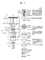
図1に、当該レーザ位相差画像取得顕微鏡の持つ位相差画像表示装置100の全体概略を示す。図2は、図1のimage plane 位置での拡大図である。拡大図についての詳細説明は、図中に記載した。
FIG. 1 shows an overall outline of a phase difference
図3は、図1に示した位相差画像表示装置100を容易に理解できるように対比して提示した特許文献3に記載された位相差画像表示装置100Aを示した。
FIG. 3 shows a phase difference
図1に示した位相差画像検査装置100(位相差画像表示装置ともいえる)100及び図3に示した位相差画像検査装置100A共、レーザ光源1から照射された可干渉性光はレンズ2,3を通して平行光束として照射される。可干渉性平行光束中に置かれたフーリエ変換レンズ(フーリエ変換レンズ手段、以下同じ)7の前側あるいはフーリエ変換レンズ7の前焦点面付近に設置された物体導入手段6に被検査物体を入れれば、そのフーリエ変換像(光回折パターン)はフーリエ変換レンズ7の後焦点面に形成される。
In the phase difference image inspection apparatus 100 (also referred to as a phase difference image display apparatus) 100 shown in FIG. 1 and the phase difference
図3の位相差画像検査装置100Aにあっては、該フーリエ変換像の零次光を、位相板(λ/4板)20を通し光強度調整の減光フィルタを通して、フーリエ変換レンズ7の後焦点面を前焦点面として設置された逆フーリエ変換レンズ9を通せば、逆フーリエ変換した物体光と位相変換して減光し平行光とされた零次参照光とが逆フーリエ変換レンズ9の集光面で位相差物体の干渉像が電子カメラ10で撮像される。
In the phase difference
図3に示される技術は、可干渉性平行レーザ光を検査物体の照射光として使ったために、検査法は極めて単純になり、従来法のように、照射光のリング絞りと集光レンズの後焦点面のリング状の位相板の位置合わせに労力を要しない。また、本技術では、フーリエ変換レンズの後焦点面に位相板と減光フィルタを置くだけで、フーリエ変換像の零次光は確実に位相画像の参照光になって、位相物体の位相差が光強度画像情報に変えられるから、本技術は、位相画像の単純化効果を持つ。 Since the technique shown in FIG. 3 uses coherent parallel laser light as the irradiation light of the inspection object, the inspection method becomes extremely simple, and as in the conventional method, after the ring diaphragm of the irradiation light and the condenser lens No effort is required to align the ring-shaped phase plate in the focal plane. Further, in the present technology, the zero-order light of the Fourier transform image is surely the reference beam of the phase image only by placing the phase plate and the attenuation filter on the back focal plane of the Fourier transform lens, and the phase difference of the phase object is The present technology has a simplification effect of the phase image because it can be converted to light intensity image information.
図1に示される位相差画像検査装置100にあっても、位相板(λ/4板)20、逆フーリエ変換レンズ9及び電子カメラ10を備え、上述した効果を達成する。位相差画像検査装置100は、位相板(λ/4板)20と偏光板23とをペアフィルタ(pair filter)として構成している。この構成によって、当該実施例は、位相画像の鮮明化という効果を達成する。更に、回転可能なλ/2板(πフィルタ)21を組み合わせている。通常、円偏光と直線偏光は干渉せず、偏光板があってはじめて同じ偏光面の光波が干渉する。この構成によって、当該実施例は、位相画像の更なる鮮明化という効果を達成する。なお、高次光の他の偏光面を持つ円偏光は物体の細部情報の明確化に寄与する。
Even in the phase difference
図1において、位相差画像検査装置100は、レーザ光源1、回転可能なλ/2板(πフィルタ)21、可干渉性拡大平行レーザ光束を形成するレーザ光拡大平行光構成光学系、可干渉性平行レーザ光束中に設置されたフーリエ変換レンズ7、このフーリエ変換レンズの前側に設けられた物体導入手段6、このフーリエ変換レンズの後焦点面に設けられてフーリエ変換像の光回折パターンの零次光だけを通す穴22を中央に備え高次回折光を円偏光に変えて透過させるλ/4板(π/2フィルタ)位相フィルタ20、前記フーリエ変換レンズの後焦点面を前焦点面として設置され、位相フィルタ20を通過した高次の回折光および零次光を集光する逆フーレ家変換レンズ9、このフーリエ変換レンズ7の前または後ろに設置された回転可能な偏光板23、および該逆フーリエ変換レンズの集光面に結像された光学像を撮影するために設置された電子カメラのそれぞれが光軸上に設置され構成される、物体導入手段6から投写される導入物体の位相差物体干渉像を形成する位相差画像作成光学系を備える。 In FIG. 1, a phase difference image inspection apparatus 100 includes a laser light source 1, a rotatable λ / 2 plate (π filter) 21, a laser light expansion parallel light configuration optical system that forms a coherent expansion parallel laser light flux, and a coherence Transform lens 7 installed in a collimated parallel laser beam, object introducing means 6 provided on the front side of this Fourier transform lens, zero on the light focal pattern of the Fourier transform image provided on the back focal plane of this Fourier transform lens A λ / 4 plate (π / 2 filter) phase filter 20 having a hole 22 at the center for passing only the next light and changing high-order diffracted light into circularly polarized light and transmitting it, and setting the back focal plane of the Fourier transform lens as the front focal plane Fourier transform lens 9 for collecting high-order diffracted light and zero-order light that has passed through the phase filter 20, and a rotatable polarization installed in front of or behind this Fourier transform lens 7 Each of the plate 23 and an electronic camera installed to capture an optical image formed on the light collecting surface of the inverse Fourier transform lens is projected on the optical axis and projected from the object introducing means 6 A phase difference image forming optical system for forming a phase difference object interference image of the introduced object.
この位相差画像作成光学系は、フーリエ変換レンズ7が可干渉性拡大平行レーザ光束中に設置されて、フーリエ変換レンズ7の前焦点面導入物体の画像を前記逆フーリエ変換レンズ9の後焦点面に結像させる後焦点面の位置に、フーリエ変換レンズ7の前焦点面上の光軸上および光軸から直角方向に外側に外れた位置の導入物体の位相差像を電子カメラ10に広い視野で撮り込むことが出来る。
λ/4板(π/2フィルタ)位相フィルタ20は、典型的にフーリエ変換レンズ7の後焦点面に設けられてフーリエ変換像の光回折パターンの零次光を通す穴22を中央に備え高次回折光を円偏光に変えて透過させる。穴22を減光フィルタで塞いで零次光を減光させることはできるが、減光フィルタの強度を連続的変えて、零次光の強度を任意に変えるために穴とすることがよい。したがって、本実施例における穴とは、物理的な穴ばかりでなく、零次光を通すことに何の障害もない手段をも意味している。
In this phase difference image forming optical system, a
The λ / 4 plate (π / 2 filter)
フーリエ変換レンズ7の前または後に設置された偏光板23が、光軸上に設置され、強度差が調整された前記透過した零次光と前記高次回折光とで、物体導入手段から投写される導入物体の位相差物体干渉像を形成する。零次光と高次光との強度比を連続的に変えられる。
A
前記フーリエ変換レンズ7の前焦点面導入物体の画像を前記逆フーリエ変換レンズ9の後焦点面に結像させる該後焦点面の位置に、前記フーリエ変換レンズ7の前焦点面上の光軸上および光軸から直角方向に外方に外れた位置の導入物体についての、強度差が調整された前記透過した零次光と前記高次回折光によって形成された位相差物体干渉像を広い視野で撮り込む。
On the optical axis on the front focal plane of the
上述したように、可干渉性拡大平行レーザ光束を形成するレーザ光拡大平行光構成光学系のレーザ光源1の後ろに回転可能なλ/2板(πフィルタ)21を備える。回転することで角度が調節される。レーザ光源1の後ろに置いたλ/2板21は直線偏光しているレーザ光の偏光面を変える(直線偏光の偏光面の角度が変わる)働きをする。λ/2板が無くても本発明の特徴は得られるが、λ/2板21を配設することによって偏光依存性を持つ試料を観測する場合に効果的な働きを得ることが出来る。
As described above, the rotatable λ / 2 plate (π filter) 21 is provided behind the laser light source 1 of the laser light expanding parallel light constructing optical system forming the coherent expanding parallel laser light flux. The angle is adjusted by rotating. The λ / 2
上述したように、偏光板23は、回転可能であり、回転することで角度が調節される。
As described above, the
穴あきλ/4板の設置位置は、前記フーリエ変換レンズ7の後焦点面であり、偏光板23の配置位置は、穴あきλ/4板の後で逆フーリエ変換レンズ9の前でも後ろでもよい。
The installation position of the perforated λ / 4 plate is the back focal plane of the
特許文献3に記載された技術では、零次光をλ/4板を通過させ減光フィルタで減光させることで散乱光との干渉を図ることに対し、本実施例では広い領域を持つλ/4板中央に零次光透過の穴22を開け、カメラ10の前方に偏光板23を置くことにより特許文献3に記載された技術とは逆に散乱高次光をλ/4板を通過させ、偏光板23通過で減光した零次光と干渉させる。
In the technique described in Patent Document 3, interference with scattered light is achieved by passing zero-order light through a λ / 4 plate and reducing light with a light reduction filter, but in the present embodiment λ By making a
λ/2板(πフィルタ)21は、πフィルタによる偏光面を形成し、λ/2板(πフィルタ)21の回転によって照射光又は零次光(赤色表示)、及び高次回折光(青色表示)を、偏光面方向に偏光させる。 The λ / 2 plate (π filter) 21 forms a polarization plane by a π filter, and irradiation light or zero-order light (red display) and high-order diffracted light (blue display) are generated by rotation of the λ / 2 plate (π filter) 21. ) Is polarized in the polarization plane direction.
試料を通った零次直線偏光と高次回折円偏光とが形成される。 Zero-order linear polarization and high-order diffracted circular polarization passing through the sample are formed.
π/2フィルタを透過した高次回折円偏光(青色表示)と零次直線偏光(赤色表示)は、図に示す形態となる。 The high-order diffracted circularly polarized light (blue display) and the zero-order linearly polarized light (red display) transmitted through the π / 2 filter have the form shown in the figure.
今、偏光板23の角度が図に示される位置(黒色表示)に調整されたとする。
Now, it is assumed that the angle of the
図に、穴あきλ/4板20と角度調節可能な偏光板23とからなるフィルタ対を透過した透過光の形態状態が黒、赤及び青色3色で表示される。偏向板23の作用によって、偏光板の偏光透過面(図で黒色表示)の方向と円偏光の高次光(青色表示)の同方向偏光透過光の強さがベクトルで示されるようになり、高次回折光の微細画像作像の寄与度が高められる。
In the figure, the form state of the transmitted light transmitted through the filter pair consisting of the perforated λ / 4
ここで、λ/4板通過の散乱高次光は円偏光になり、偏光板での減衰が少ないことから、偏光板23を零次光の口径にあわせ微細加工する必要がないという簡便さの利点が得られる。
Here, since the scattered high-order light passing through the λ / 4 plate is circularly polarized and has less attenuation at the polarizing plate, there is the advantage of simplicity that there is no need to finely process the
穴あきλ/4板20と角度調節可能な偏光板23とからなるフィルタ対を用いることで、次のような利点が得られる。
(1)広いλ/4板で回折光を高次光まで取り込むことにより高次光による微細画像再構成で輪郭明確化が実現される。
(2)λ/4板中央に零次光透過穴を開けることにより、試料透過の零次光が自己干渉を起こすことを防ぎ、従来型に生ずる零次光干渉の効果による、後光効果(halo effect)を防ぐことができる。
(3)偏光板の角度調整により、零次光を減衰させ、バックグラウンド光を弱めることで、散乱光強度を相対的に強め、零次光のバックグラウンド光と高次散乱光との干渉を強め、画像のコントラストを強め、検査体の輪郭ばかりでなく内部構造までも明確な画像とすることができる。
The following advantages can be obtained by using a filter pair consisting of the perforated λ / 4
(1) By taking diffracted light into high-order light with a wide λ / 4 plate, contour clarification is realized by fine image reconstruction by high-order light.
(2) By opening a zero-order light transmission hole at the center of the λ / 4 plate, it is possible to prevent the zero-order light transmitted through the sample from causing self-interference, and the back light effect Halo effect can be prevented.
(3) By adjusting the angle of the polarizing plate to attenuate the zero-order light and weaken the background light, the scattered light intensity is relatively strengthened, and the interference between the zero-order light background light and the high-order scattered light is The image can be intensified, the image contrast can be intensified, and not only the outline of the object but also the internal structure can be made clear.
図4は、位相差画像検査装置100(図4(a))及び引用文献3に記載された位相差画像検査装置100Aによって取得されたガラス破片の顕微鏡画像(図4(b))の比較を示す図である。
FIG. 4 shows a comparison of microscopic images (FIG. 4 (b)) of glass fragments obtained by the phase
本実施例によって取得された画像はガラス破片の傾斜部の厚さ情報が図に示されるように内部が等高線になって現れ、位相差情報が引用文献3に記載された位相差画像検査装置によって取得されたガラス破片の顕微鏡画像に比べて輪郭ばかりでなく内部まで明確に現われる。 In the image obtained according to the present embodiment, the thickness information of the inclined portion of the glass fragments appears as contour lines as shown in the figure, and the phase difference information is recorded by the phase difference image inspection apparatus described in reference 3 Not only the contour but also the interior clearly appears as compared to the microscopic image of the glass fragments obtained.
また、透明物体の微細な情報が細部に亘って明確になり、取得画像は引用文献3に記載された位相差画像検査装置によって取得されたガラス破片の顕微鏡画像と質的に異なることが示されている。 In addition, it is shown that the minute information of the transparent object becomes clear in detail, and the acquired image is qualitatively different from the microscopic image of the glass fragments acquired by the phase-contrast image inspection device described in reference 3 ing.
図1、図2において、2のλ/2板(πフィルタ)の代わりにλ/4板(π/2フィルタ)とし、穴あきλ/4板(π/2フィルタ)の代わりにガラス板の中央に貼った零次光だけが通る大きさの円形λ/4板とした位相フィルタの組み合わせによっても、上述した効果と同等の効果を生じさせることができる。この組み合わせフィルタでも、高次回折光は円偏光となり、零次光は直線偏光となるので、カメラの前に設置された偏光板23によって、同等の効果が生ずる。すなわち、零次光を直線偏光とする零次光の直線偏光化フィルタ手段及び高次回折光を円偏光とする高次回折光円偏光化フィルタ手段を設ける。
In Fig. 1 and Fig. 2, instead of 2 λ / 2 plate (π filter), λ / 4 plate (π / 2 filter) is used, and instead of perforated λ / 4 plate (π / 2 filter), glass plate is used The same effect as the above-described effect can also be produced by combining a phase filter having a circular λ / 4 plate with a size through which only zero-order light passes in the center. Also in this combined filter, the high-order diffracted light is circularly polarized and the zero-order light is linearly polarized, so the
本実施例は、ポリスチレンラテックス20.3μm、10.3μm及び5.0μm標準粒子群についても適用して粒子画像の縁が引用文献3に記載された位相差画像検査装置によって取得された顕微鏡画像に比べて明確に現われた。 This embodiment is also applied to polystyrene latex 20.3 μm, 10.3 μm and 5.0 μm standard particle groups, and the microscope image obtained by the phase-contrast image inspection device whose edge of the particle image is described in reference 3 It clearly appeared in comparison.
以上に示したように、複数形状の同時並列実時間識別が可能とされる。 As described above, simultaneous and real-time identification of a plurality of shapes is possible.
レーザ位相差画像取得顕微鏡を用いた生体細胞の観測方法において、
試料が生体細胞であって、
当該細胞に均一強度で平行な干渉性レーザ光を試料に照射して画像を形成し、画像に表示された内の細胞を特定し、特定した細胞についての散乱回析光の高次光までも取り込み、
取り込まれた散乱回析光の内、高次光と零次光とをフイルタで、継続して干渉させ、時々刻々に変化する当該細胞の細胞外観形状(A1)及び細胞サイズ(A2)を含む細胞外観変化現象(A)と、細胞内形状(B1)及び細胞内小器官サイズ(B2)を含む細胞内構造変化現象(B)と、になる変化現象からなる観測データを時々刻々に取得し、当該組み合わせになるいずれかの変化現象もしくは全ての変化現象に基づいて画像化された時々刻々の干渉画像を取得する。
In a method of observing a living cell using a laser phase contrast imaging microscope,
The sample is a living cell and
The sample is irradiated with coherent laser light of uniform intensity and parallel to the cells to form an image, the cells displayed in the image are identified, and higher-order light of scattered diffraction light of the identified cells is also incorporated,
Of the incorporated scattered diffraction light, a filter is used to continuously interfere with the high order light and the zero order light with a filter, and the cell appearance including the cell appearance shape (A1) and the cell size (A2) of the cell which changes from moment to moment Observation data consisting of the change phenomenon (B) including the change phenomenon (A) and the intracellular structure change phenomenon (B) including the intracellular shape (B1) and the intracellular organelle size (B2) are acquired from time to time, A point-in-time interference image is acquired which is imaged on the basis of any or all of the combination phenomena being combined.
当該レーザ位相差画像取得顕微鏡を用いることで、取り込まれた散乱回析光の内、高次光と零次光とをフイルタで、継続して干渉させ、時々刻々に変化する当該細胞の細胞外観形状(A1)及び細胞サイズ(A2)を含む細胞外観変化現象(A)と、細胞内形状(B1)及び細胞内小器官サイズ(B2)を含む細胞内構造変化現象(B)と、になる変化現象からなる観測データを時々刻々に取得できることが分かった。 By using the laser phase contrast image acquisition microscope, among the captured scattered diffraction light, the high-order light and the zero-order light are continuously interfered with a filter, and the cell external appearance shape of the cell changes from moment to moment ((2) A1) The cell appearance change phenomenon (A) including the cell size (A2), and the intracellular change phenomenon (B) including the intracellular shape (B1) and the intracellular organelle size (B2) It turned out that the observation data consisting of can be acquired every moment.
図5は、変化現象に基づいて画像化された干渉画像200を模式的に示す図である。
FIG. 5 is a view schematically showing an
図5において、変化現象は、当該細胞の細胞外観形状(A1)及び細胞サイズ(A2)を含む細胞外観変化現象(A)と、細胞内形状(B1)及び細胞内小器官サイズ(B2)を含む細胞内構造変化現象(B)と、になる変化現象からなる。 In FIG. 5, the change phenomenon includes the cell appearance change phenomenon (A) including the cell appearance shape (A1) and the cell size (A2) of the cells, the intracellular shape (B1) and the intracellular organelle size (B2). It consists of a change phenomenon that becomes an intracellular structural change phenomenon (B), and so on.
図5において、細胞外観形状(A1)として、新突起発生
細部サイズ(A2)として、細胞サイズ変化
細胞内形状(B1)として、新膜発生、新核内膜発生、新小器官発生、
細胞内小器官減、核内小器官形状変化
細胞内小器官サイズ(B2)として、小器官サイズ変化、核内小器官サ
イズ変化
が示される。当該レーザ位相差画像取得顕微鏡を用いることで、細胞外観変化現象(A)と細胞内構造変化現象(B)とを組み合わせたこれらの変化現象を観察することができる。
In FIG. 5, as a cell appearance shape (A1), new process generation
Cell size change as detail size (A2)
As intracellular shape (B1), new membrane development, new nuclear endometrial development, new organelle development,
Decreased intracellular organelles, nuclear organelle shape change
As organelle size (B2), organelle size change, nuclear organelle size
Change is shown. By using the said laser phase contrast image acquisition microscope, these change phenomena which combined the cell external appearance change phenomenon (A) and the intracellular structure change phenomenon (B) can be observed.
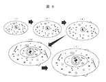
図6は、取り込まれた散乱回析光の内、高次光と零次光とをフイルタで、継続して干渉させ、時々刻々に変化する当該細胞の細胞外観変化現象(A)及び細胞内構造変化現象(B)になる変化現象からなる観測データを時々刻々に取得する状況を示す図である。
図6(i)から(v)に示されるように当該細胞の細胞外観及び細胞内構造は、時々刻々に変化する。このように変化する変化現象が、細胞外観形状(A1)及び細胞サイズ(A2)を含む細胞外観変化現象(A)と、細胞内形状(B1)及び細胞内小器官サイズ(B2)を含む細胞内構造変化現象(B)として観測され、観測データとして取得される。取得された観測データは、レーザ位相差画像取得顕微鏡に付随して設けられたコンピュータ、例えばパソコンに送信され、その画像装置の画面に直ちに撮像された干渉画像として表示される。
FIG. 6 shows the change in the cell appearance (A) and the intracellular structure change of the cells, in which the higher-order light and the zero-order light are continuously interfered with each other by the filter among the scattered and scattered light taken up. It is a figure which shows the condition which acquires observation data which consist of a change phenomenon used as a phenomenon (B) momentarily.
As shown in FIGS. 6 (i) to (v), the cell appearance and the intracellular structure of the cells change from time to time. Such change phenomena include cell appearance change phenomenon (A) including cell appearance shape (A1) and cell size (A2), and cells including intracellular shape (B1) and intracellular organelle size (B2) It is observed as an internal structure change phenomenon (B) and acquired as observation data. The acquired observation data is transmitted to a computer, for example, a personal computer, provided in addition to the laser phase difference image acquisition microscope, and displayed as an interference image immediately captured on the screen of the imaging device.
その画像装置の画面に直ちに撮像された干渉画像として表示する場合に、観測者のニーズに従って干画像の内の一部分を画像削除手段用いて削除することで、画面に表示することができる。変化現象からなる観測データを時々刻々に取得し、当該組み合わせになるいずれかの変化現象もしくは全ての変化現象に基づいて画像化された時々刻々の干渉画像を取得することができる。 When displaying as an interference image immediately captured on the screen of the image device, it is possible to display on the screen by deleting a part of the dry image using the image deleting means according to the needs of the observer. Observation data consisting of change phenomena can be acquired momentarily, and momentary interference images imaged on the basis of any change phenomenon or all alteration phenomena in the combination can be acquired.
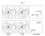
図7は、細胞外観形状(A1)及び細胞サイズ(A2)を含む細胞外観変化現象(A)と、細胞内形状(B1)及び細胞内小器官サイズ(B2)を含む細胞内構造変化現象(B)の時々刻々に変化する現象について、変化の前後の変化分を時々刻々の干渉画像として取得して表示した例を示す。これらの例では、上図に、新器官発生と小器官サイズ変化が抽出されて表示された。下図に、細胞外観形状変化としての新突起発生が抽出され、表示された。これらの変化が双方あった場合には、これらの変化が組み合わされて画面に表示される。 FIG. 7 shows a cell appearance change phenomenon (A) including cell appearance shape (A1) and cell size (A2), and an intracellular structure change phenomenon (cell shape (B1) and intracellular organelle size (B2). An example is shown in which the variation before and after the change is acquired and displayed as an interference image from moment to moment about the phenomenon that changes from moment to moment in B). In these examples, neonatal development and organelle size change were extracted and displayed in the upper figure. In the figure below, the occurrence of new projections as cell appearance shape change was extracted and displayed. If both of these changes occur, these changes are combined and displayed on the screen.
時々刻々の干渉画像の時間的に前後の干渉画像の比較による当該細胞の細胞外観形状(A1)及び細胞サイズ(A2)を含む細胞外観変化現象(A)と、細胞内形状(B1)及び細胞内小器官サイズ(B2)を含む細胞内構造変化現象(B)と、になる変化現象を取得し、当該変化現象から細胞の種類を同定することが可能になる。 Cell appearance change phenomenon (A) including the cell appearance shape (A1) and cell size (A2) of the cell by comparison of interference images before and after from time to time, intracellular shape (B1) and cells It becomes possible to obtain the change phenomenon that becomes the intracellular structural change phenomenon (B) including the organelle size (B2) and the change phenomenon and to identify the cell type from the change phenomenon.
試料がん生体細胞である場合、時々刻々の干渉画像の時間的に前後の干渉画像の比較による当該細胞の細胞外観形状(A1)及び細胞サイズ(A2)を含む細胞外観変化現象(A)と、細胞内形状(B1)及び細胞内小器官サイズ(B2)を含む細胞内構造変化現象(B)と、になる変化現象を取得し、当該変化現象から変化現象で特定された、細胞増殖が激しいがん細胞の種類を同定することに寄与できる。 In the case of a sample cancer living cell, a cell appearance change phenomenon (A) including the cell appearance shape (A1) and the cell size (A2) of the cell by comparison of interference images before and after in time Obtain a change phenomenon that becomes an intracellular structure change phenomenon (B) including an intracellular shape (B1) and an intracellular organelle size (B2), and from the change phenomenon, cell proliferation specified by the change phenomenon is obtained. It can contribute to identifying the type of intense cancer cells.
当該細胞の細胞外観形状(A1)及び細胞サイズ(A2)を含む細胞外観変化現象(A)と、細胞内形状(B1)及び細胞内小器官サイズ(B2)を含む細胞内構造変化現象(B)二に分けたが、細胞内構造変化現象(B)を細分化して、細胞内構造変化現象と核内構造変化現象とに分けることができる。
Cell appearance change phenomenon (A) including the cell appearance shape (A1) and cell size (A2) of the cells, and intracellular structure change phenomenon (B) including the intracellular shape (B1) and the intracellular organelle size (B2) 2.) It is divided into two, but the intracellular structural change phenomenon (B) can be subdivided into an intracellular structural change phenomenon and a nuclear structural change phenomenon.
図8〜図15は、観察した肺がん細胞の変化状況を捉えた画像である。試料が肺がんの生体細胞である。試料が肺がんの生体細胞に特定されず、特に増殖性細胞の詳細な観測が必要とされる試料について効果があるが、以下、試料を肺がんの生体細胞に特定して説明する。 FIGS. 8 to 15 are images capturing changes in observed lung cancer cells. The sample is a living cell of lung cancer. Although the sample is not specified as a lung cancer biological cell and is particularly effective for a sample that requires detailed observation of proliferative cells, the sample is specified and described as a lung cancer biological cell.
図8は、観察した肺がん細胞の全体視野画像を示す。 FIG. 8 shows a whole field image of observed lung cancer cells.
図9は、図8の全体視野画像が時々刻々に変化する状況を取り出して示した図である。 FIG. 9 is a diagram showing a situation in which the entire view image of FIG. 8 changes from moment to moment.
図10は、がん細胞形状変化と細胞核形状変化を捉えた観測データから表示された画像を示す。 FIG. 10 shows an image displayed from observation data capturing cancer cell shape change and cell nucleus shape change.
図11は、図10の観測データが時々刻々に変化する状況を取り出して示した図である。 FIG. 11 is a diagram showing the situation where the observation data of FIG. 10 changes momentarily.
図12は、がん細胞形状変化と細胞核の形状・核内小器官の変化を捉えた観測データから表示された画像を示す。 FIG. 12 shows an image displayed from observation data capturing changes in cancer cell shape and changes in the shape of the cell nucleus and organelles in the nucleus.
図13は、図12の観測データが時々刻々に変化する状況を取り出して示した図である。 FIG. 13 is a diagram showing the situation where the observation data of FIG. 12 changes every moment.
図14は、全体視野画像の中で特定され、切り出された画像領域内に存在する複数の細胞の内の他方の細胞について、がん細胞形状変化と細胞核の形状・小器官変化を捉えた観測データから表示された画像を示す。 FIG. 14 is an observation that captures changes in the shape of cancer cells and changes in the shape of the cell nucleus and changes in the shape of the cell nuclei and organelles in the other cells of the plurality of cells identified in the entire visual field image and present in the extracted image area Shows the image displayed from the data.
図15は、図14の観測データが時々刻々に変化する状況を取り出して示した図である。 FIG. 15 is a diagram showing a situation in which the observation data of FIG. 14 changes momentarily.
よって、図8を見るときには、図9を参照する手法で、二つの図をペアでみることが勧められる。以下、同様である。また、図8の画像を取得したときに、図9に示される画像が画像加工ソフトウエアによって容易に取得される。 Thus, when viewing FIG. 8, it is recommended to view the two figures in pairs in the manner referring to FIG. The same applies below. Also, when the image of FIG. 8 is acquired, the image shown in FIG. 9 is easily acquired by the image processing software.
図8、図9において、当該細胞に均一強度で平行な干渉性レーザ光が試料である肺がん生体細胞に照射されて全体視野画像が形成され、画像に表示された複数の細胞の内、いくつかの細胞を含む領域が特定され、観測領域とされた。観測領域が図面上に枠で示される。 In FIGS. 8 and 9, coherent laser light having a uniform intensity and parallel to the cells is irradiated to a lung cancer living cell as a sample to form a whole field image, and some of the plurality of cells displayed in the image The area containing the cells of was identified as the observation area. The observation area is indicated by a frame on the drawing.
図10、図11において、画面に、がん細胞形状変化と細胞核形状変化を捉えた干渉画像が表示された。左上に、模式的にこれらの変化状況を示した。これらの画面から分かるように、一つの画面上に、細胞外観変化現象(A)として、がん細胞形状変化ばかりでなく、細胞サイズに変化が表示され、さらに細胞内構造変化現象(B)として、細胞核形状変化干渉画像が表示された。 In FIG. 10 and FIG. 11, the interference image which captured the cancer cell shape change and the cell-nucleus shape change was displayed on the screen. In the upper left, these changes are shown schematically. As can be seen from these screens, not only cancer cell shape change but also change in cell size are displayed as cell appearance change phenomenon (A) on one screen, and further as intracellular structure change phenomenon (B) Cell nucleus shape change interference image was displayed.
図12、図13において、画面に、がん細胞形状変化と細胞核の形状・核内小器官の変化を捉えた干渉画像が表示された。左上に、模式的にこれらの変化状況を示した。これらの画面から分かるように、一つの画面上に、細胞外観変化現象(A)として、がん細胞形状変化ばかりでなく、細胞サイズが増大した状況を示す変化が表示され、さらに細胞内構造変化現象(B)として、細胞核の形状・核内小器官変化干渉画像が表示された。 In FIG. 12 and FIG. 13, the interference image which captured the change of the cancer cell shape, the shape of the cell nucleus, and the change of the nuclear organelle was displayed on the screen. In the upper left, these changes are shown schematically. As can be seen from these screens, on one screen, not only cancer cell shape change but also change showing the situation of increased cell size are displayed as cell appearance change phenomenon (A), and further intracellular structure change As the phenomenon (B), the shape of the cell nucleus and the nuclear organelle change interference image were displayed.
図14、図15において、画面に、他方の細胞について、がん細胞形状変化と細胞核の形状・核内小器官の変化を捉えた干渉画像が表示された。左上に、模式的にこれらの変化状況を示した。これらの画面から分かるように、一つの画面上に、他方の細胞について、細胞外観変化現象(A)として、がん細胞形状変化ばかりでなく、細胞サイズに変化が表示され、さらに細胞内構造変化現象(B)として、細胞核の形状・核内小器官変化干渉画像が表示された。図11に示されるように、一つの画面上に、複数の細胞について、細胞外観変化現象(A)として、がん細胞形状変化ばかりでなく、細胞サイズに変化が表示され、さらに細胞内構造変化現象(B)として、細胞核の形状・核内小器官変化干渉画像を表示することができる。広い領域で細胞内部まで一度に観察することの出来る干渉画像が提供される。 In FIG. 14 and FIG. 15, the interference image which displayed the change of a cancer cell shape, the shape of a cell nucleus, and the change of the nuclear organelle about the other cell was displayed on the screen. In the upper left, these changes are shown schematically. As can be seen from these screens, not only cancer cell shape change but also cell size change is displayed on one screen as cell appearance change phenomenon (A) for the other cell, and further intracellular structure change As the phenomenon (B), the shape of the cell nucleus and the nuclear organelle change interference image were displayed. As shown in FIG. 11, not only cancer cell shape change but also change in cell size are displayed as cell appearance change phenomenon (A) for a plurality of cells on one screen, and further intracellular structural change As the phenomenon (B), it is possible to display a shape of a cell nucleus and a nuclear organelle change interference image. An interference image is provided which can be observed at one time to the inside of the cell in a wide area.
これらの画像から分かるように、本実施例によれば、前処理を要さず、検体組織中の癌細胞の活発な動きを実時間で時々刻々に画像検査することが可能とされ、初期段階のがん疾患を迅速・明確に診断するための支援画面が提供される。この支援画面は、非染色実時間の時々刻々検査を可能とさせ、機能的な診断を可能とさせる。がん細胞採取のその場での判定を可能とし、判定に要する時間は、数分から1時間もあれば十分であり、短時間診断に寄与することになる。
As can be seen from these images, according to the present embodiment, it is possible to image the active movement of cancer cells in the sample tissue in real time from moment to moment without requiring pretreatment. A support screen is provided for the rapid and clear diagnosis of cancer diseases. This support screen enables non-staining real-time examination every moment and enables functional diagnosis. The determination of cancer cells in situ can be made, and the time required for the determination may be several minutes to one hour, which contributes to a short time diagnosis.
本実施例の実施に際して、生体細胞を染色や薄切理などの加工を要せず、細胞、細胞核、細胞内小器官の実時間の時々刻々の動きからこれら細胞の観測画像を取得でき、特に増殖によって動きの激しいがん細胞の観測画像を取得できる。このように、本発明によれば、当該位相差顕微鏡をがん細胞など生体細胞の非染色実時間検査用顕微干渉計として用いて、従来の検査装置と比較してその機能の細部観察上の優位性を生かし、「機能的診断法」の有効な支援手段を提供することができる。 At the time of implementation of this embodiment, it is possible to obtain observation images of the cells from the momentary movement of real time of the cells, the cell nucleus and the subcellular organelle without requiring processing such as staining and thinning of the living cells, especially It is possible to acquire an observation image of a cancer cell with strong movement by proliferation. As described above, according to the present invention, the phase contrast microscope is used as a microscopic interferometer for non-staining real-time examination of living cells such as cancer cells, and compared with the conventional examination apparatus in detail observation of its function. It is possible to provide an effective means of supporting “functional diagnostic methods” by taking advantage of its superiority.
1:光源(レーザ)
2:レンズ
3:レンズ
6:物体導入手段
7:フーリエ変換レンズ
9:逆フーリエ変換レンズ
10:電子カメラまたはCCDカメラ
20:λ/4板(π/2フィルタ)位相フィルタ(位相フィルタ手段)
21:λ/2板(πフィルタ)
22:穴
23:偏光板
1: Light source (laser)
2: Lens 3: Lens 6: Object introduction means 7: Fourier transform lens 9: Inverse Fourier transform lens 10: Electronic camera or CCD camera 20: λ / 4 plate (π / 2 filter) phase filter (phase filter means)
21: λ / 2 plate (π filter)
22: hole 23: polarizing plate
Claims (6)
試料が生体細胞であって、
当該細胞に均一強度で平行な干渉性レーザ光を試料に照射して画像を形成し、画像に表示された内の細胞を特定し、特定した細胞についての散乱回析光の高次光までも取り込み、
取り込まれた散乱回析光の内、高次光と零次光とをフイルタで、継続して干渉させ、時々刻々に変化する当該細胞の細胞外観変化現象(A)及び細胞内構造変化現象(B)になる変化現象からなる観測データを時々刻々に取得すること
を特徴とするレーザ位相差画像取得顕微鏡による生体細胞の観測方法。 The sample is irradiated with coherent laser light of uniform intensity and parallel to the sample, high-order light of the scattered diffraction light including fine image information is also taken in, and the high-order light and the zero-order light among the scattered diffraction light are interfered by the optical filter. In an observation method of a living cell by a laser phase contrast image acquisition microscope capable of acquiring observation data of a minute part of a sample and acquiring an imaged interference image,
The sample is a living cell and
The sample is irradiated with coherent laser light of uniform intensity and parallel to the cells to form an image, the cells displayed in the image are identified, and higher-order light of scattered diffraction light of the identified cells is also incorporated,
Among the scattered and diffracted light taken in, the filter sequentially interferes with the higher-order light and the zero-order light and changes the cell appearance of the cell (A) and the intracellular structure change (B) which change from moment to moment The observation method of biological cells with a laser phase contrast image acquisition microscope characterized by acquiring observation data consisting of change phenomena every moment.
試料が生体細胞であって、
当該細胞に均一強度で平行な干渉性レーザ光を試料に照射して画像を形成し、画像に表示された内の細胞を特定し、特定した細胞についての散乱回析光の高次光までも取り込み、
取り込まれた散乱回析光の内、高次光と零次光とをフイルタで、継続して干渉させ、時々刻々に変化する当該細胞の細胞外観形状(A1)及び細胞サイズ(A2)を含む細胞外観変化現象(A)と、細胞内形状(B1)及び細胞内小器官サイズ(B2)を含む細胞内構造変化現象(B)と、になる変化現象からなる観測データを時々刻々に取得し、当該組み合わせになるいずれかの変化現象もしくは全ての変化現象に基づいて画像化された時々刻々の干渉画像を取得すること
を特徴とするレーザ位相差画像取得顕微鏡を用いた生体細胞の観測方法。 The sample is irradiated with coherent laser light of uniform intensity and parallel to the sample, high-order light of the scattered diffraction light including fine image information is also taken in, and the high-order light and the zero-order light among the scattered diffraction light are interfered by the optical filter. In a method of observing a living cell using a laser phase contrast image acquisition microscope capable of acquiring observation data of a minute part of a sample and acquiring an imaged interference image,
The sample is a living cell and
The sample is irradiated with coherent laser light of uniform intensity and parallel to the cells to form an image, the cells displayed in the image are identified, and higher-order light of scattered diffraction light of the identified cells is also incorporated,
Of the incorporated scattered diffraction light, a filter is used to continuously interfere with the high order light and the zero order light with a filter, and the cell appearance including the cell appearance shape (A1) and the cell size (A2) of the cell which changes from moment to moment Observation data consisting of the change phenomenon (B) including the change phenomenon (A) and the intracellular structure change phenomenon (B) including the intracellular shape (B1) and the intracellular organelle size (B2) are acquired from time to time, A method of observing a living cell using a laser phase contrast image acquisition microscope, which comprises acquiring an intermittent interference image imaged on the basis of any change phenomenon or all change phenomena to be combined.
試料が生体細胞であって、
当該細胞に均一強度で平行な干渉性レーザ光を試料に照射して画像を形成し、画像に表示された内の細胞を特定し、特定した細胞についての散乱回析光の高次光までも取り込み、
取り込まれた散乱回析光の内、高次光と零次光とをフイルタで、継続して干渉させ、時々刻々に変化する当該細胞の細胞外観変化現象(A)及び細胞内構造変化現象(B)になる変化現象からなる観測データを時々刻々に取得すること
を特徴とするレーザ位相差画像取得顕微鏡。 The sample is irradiated with coherent laser light of uniform intensity and parallel to the sample, high-order light of the scattered diffraction light including fine image information is also taken in, and the high-order light and the zero-order light among the scattered diffraction light are interfered by the optical filter. In a laser phase difference image acquisition microscope capable of acquiring observation data of a minute part of a sample and acquiring an imaged interference image,
The sample is a living cell and
The sample is irradiated with coherent laser light of uniform intensity and parallel to the cells to form an image, the cells displayed in the image are identified, and higher-order light of scattered diffraction light of the identified cells is also incorporated,
Among the scattered and diffracted light taken in, the filter sequentially interferes with the higher-order light and the zero-order light and changes the cell appearance of the cell (A) and the intracellular structure change (B) which change from moment to moment A laser phase-contrast image acquisition microscope characterized by acquiring observation data consisting of change phenomena every moment.
試料が生体細胞であって、
当該レーザ位相差画像取得顕微鏡が、
当該細胞に均一強度で平行な干渉性レーザ光を試料に照射して画像を形成し、画像に表示された内の細胞を特定し、特定した細胞についての散乱回析光の高次光までも取り込み、
取り込まれた散乱回析光の内、高次光と零次光とをフイルタで、継続して干渉させ、時々刻々に変化する当該細胞の細胞外観形状(A1)及び細胞サイズ(A2)を含む細胞外観変化現象(A)と、細胞内形状(B1)及び細胞内小器官サイズ(B2)を含む細胞内構造変化現象(B)と、になる変化現象からなる観測データを時々刻々に取得し、
生体細胞観測手段が、
当該組み合わせになるいずれかの変化現象もしくは全ての変化現象に基づいて画像化された時々刻々の干渉画像を取得すること
を特徴とするレーザ位相差画像取得顕微鏡を用いた生体細胞観測装置。 The sample is irradiated with coherent laser light of uniform intensity and parallel to the sample, high-order light of the scattered diffraction light including fine image information is also taken in, and the high-order light and the zero-order light among the scattered diffraction light are interfered by the optical filter. In a biological cell observation apparatus using a laser phase contrast image acquisition microscope capable of acquiring observation data of a minute part of a sample and acquiring an imaged interference image,
The sample is a living cell and
The laser phase contrast image acquisition microscope
The sample is irradiated with coherent laser light of uniform intensity and parallel to the cells to form an image, the cells displayed in the image are identified, and higher-order light of scattered diffraction light of the identified cells is also incorporated,
Of the incorporated scattered diffraction light, a filter is used to continuously interfere with the high order light and the zero order light with a filter, and the cell appearance including the cell appearance shape (A1) and the cell size (A2) of the cell which changes from moment to moment The observation data consisting of the change phenomenon (B) including the change phenomenon (A) and the intracellular structure change phenomenon (B) including the intracellular shape (B1) and the intracellular organelle size (B2) are acquired from time to time,
Means of observing living cells
An organism cell observation device using a laser phase contrast image acquisition microscope, characterized in that an interference image is acquired momentarily which is imaged based on any change phenomenon or all change phenomena which become the combination.
Priority Applications (1)
| Application Number | Priority Date | Filing Date | Title |
|---|---|---|---|
| JP2017237319A JP2019105703A (en) | 2017-12-12 | 2017-12-12 | Phase difference image inspection device and phase difference image inspection method |
Applications Claiming Priority (1)
| Application Number | Priority Date | Filing Date | Title |
|---|---|---|---|
| JP2017237319A JP2019105703A (en) | 2017-12-12 | 2017-12-12 | Phase difference image inspection device and phase difference image inspection method |
Publications (1)
| Publication Number | Publication Date |
|---|---|
| JP2019105703A true JP2019105703A (en) | 2019-06-27 |
Family
ID=67062395
Family Applications (1)
| Application Number | Title | Priority Date | Filing Date |
|---|---|---|---|
| JP2017237319A Pending JP2019105703A (en) | 2017-12-12 | 2017-12-12 | Phase difference image inspection device and phase difference image inspection method |
Country Status (1)
| Country | Link |
|---|---|
| JP (1) | JP2019105703A (en) |
Cited By (2)
| Publication number | Priority date | Publication date | Assignee | Title |
|---|---|---|---|---|
| JP2020089368A (en) * | 2003-08-01 | 2020-06-11 | ビーエーエスエフ プラント サイエンス ゲーエムベーハー | Method for producing polyunsaturated fatty acids in transgenic organisms |
| KR20220006221A (en) | 2020-07-08 | 2022-01-17 | 재단법인대구경북과학기술원 | Imaging System |
Citations (9)
| Publication number | Priority date | Publication date | Assignee | Title |
|---|---|---|---|---|
| JPH06225220A (en) * | 1993-01-25 | 1994-08-12 | Fujitsu Ltd | Radiation image display device |
| JPH06237917A (en) * | 1993-02-19 | 1994-08-30 | Hitachi Ltd | Time sequential image data display method |
| WO2007139201A1 (en) * | 2006-05-31 | 2007-12-06 | Olympus Corporation | Organism specimen imaging method and organism specimen imaging device |
| JP2011239778A (en) * | 2010-04-23 | 2011-12-01 | Nagoya Univ | Screening method of chemical substance |
| JP2014504882A (en) * | 2011-02-01 | 2014-02-27 | ナノ3ディー バイオサイエンスィズ,インコーポレイテッド | 3D cell viability assay |
| JP2016184224A (en) * | 2015-03-25 | 2016-10-20 | 株式会社日立ハイテクノロジーズ | Cell diagnosis support apparatus, cell diagnosis support method, remote diagnosis support system, service providing system, and image processing method |
| JP2017016628A (en) * | 2015-06-30 | 2017-01-19 | ソニー株式会社 | Information processor, information processing system, and information processing method |
| JP2017129760A (en) * | 2016-01-21 | 2017-07-27 | 有限会社 高度技術研究所 | Phase difference image inspection device and phase difference image inspection method |
| JP2017205053A (en) * | 2016-05-18 | 2017-11-24 | 富士フイルム株式会社 | Imaging apparatus and method |
-
2017
- 2017-12-12 JP JP2017237319A patent/JP2019105703A/en active Pending
Patent Citations (9)
| Publication number | Priority date | Publication date | Assignee | Title |
|---|---|---|---|---|
| JPH06225220A (en) * | 1993-01-25 | 1994-08-12 | Fujitsu Ltd | Radiation image display device |
| JPH06237917A (en) * | 1993-02-19 | 1994-08-30 | Hitachi Ltd | Time sequential image data display method |
| WO2007139201A1 (en) * | 2006-05-31 | 2007-12-06 | Olympus Corporation | Organism specimen imaging method and organism specimen imaging device |
| JP2011239778A (en) * | 2010-04-23 | 2011-12-01 | Nagoya Univ | Screening method of chemical substance |
| JP2014504882A (en) * | 2011-02-01 | 2014-02-27 | ナノ3ディー バイオサイエンスィズ,インコーポレイテッド | 3D cell viability assay |
| JP2016184224A (en) * | 2015-03-25 | 2016-10-20 | 株式会社日立ハイテクノロジーズ | Cell diagnosis support apparatus, cell diagnosis support method, remote diagnosis support system, service providing system, and image processing method |
| JP2017016628A (en) * | 2015-06-30 | 2017-01-19 | ソニー株式会社 | Information processor, information processing system, and information processing method |
| JP2017129760A (en) * | 2016-01-21 | 2017-07-27 | 有限会社 高度技術研究所 | Phase difference image inspection device and phase difference image inspection method |
| JP2017205053A (en) * | 2016-05-18 | 2017-11-24 | 富士フイルム株式会社 | Imaging apparatus and method |
Cited By (2)
| Publication number | Priority date | Publication date | Assignee | Title |
|---|---|---|---|---|
| JP2020089368A (en) * | 2003-08-01 | 2020-06-11 | ビーエーエスエフ プラント サイエンス ゲーエムベーハー | Method for producing polyunsaturated fatty acids in transgenic organisms |
| KR20220006221A (en) | 2020-07-08 | 2022-01-17 | 재단법인대구경북과학기술원 | Imaging System |
Similar Documents
| Publication | Publication Date | Title |
|---|---|---|
| US11644791B2 (en) | Holographic imaging device and data processing method therefor | |
| EP3065001B1 (en) | Holographic microscope and data processing method for high-resolution hologram image | |
| CN102749834B (en) | Optical microscopic imaging system and imaging method | |
| WO2020087966A1 (en) | Three-dimensional diffraction tomography microscopic imaging method based on led array coding illumination | |
| CN107290846A (en) | The quantitative phase micro imaging method of LED illumination is may be programmed based on ring-type | |
| CN108982456B (en) | Three-dimensional live cell super-resolution microscopy imaging method and device based on evanescent wave illumination | |
| CN109709786B (en) | Super-resolution digital holographic imaging system and imaging method | |
| US10132609B2 (en) | Gradient light interference microscopy for 3D imaging of unlabeled specimens | |
| JP2009521216A (en) | Methods and apparatus for cell sample analysis | |
| CN108169173A (en) | A kind of big visual field high-resolution three dimensional diffraction chromatography micro imaging method | |
| CN104567659A (en) | Vortex light lighting-based dark field digital holographic microscopy device and method | |
| Wan et al. | Parallel phase-shifting self-interference digital holography with faithful reconstruction using compressive sensing | |
| KR100924574B1 (en) | Polarized phase microscope | |
| JP5733940B2 (en) | Method and apparatus for phase contrast image inspection | |
| JP6603588B2 (en) | Phase difference image inspection apparatus and phase difference image inspection method | |
| Chang et al. | Computational approach to dark-field optical diffraction tomography | |
| JP2019105703A (en) | Phase difference image inspection device and phase difference image inspection method | |
| Rathor et al. | Single-Shot Quantitative Polarization Imaging of Live Cancer Cells | |
| CN112596362A (en) | Full-field super-resolution digital holographic device and imaging method | |
| Liu et al. | Coherent noise reduction of reconstruction of digital holographic microscopy using a laterally shifting hologram aperture | |
| Gao | Development and applications of digital holography to particle field measurement and in vivo biological imaging | |
| CN203929011U (en) | Hyperchannel white light common path interference micro tomography system based on crossed polarized light | |
| CN109780993B (en) | Differential Phase Contrast Microscopy System and Method | |
| JP6694182B2 (en) | Micro sample observation system and micro sample observation method | |
| Cheng et al. | Superresolution imaging in synthetic aperture digital holographic microscopy |
Legal Events
| Date | Code | Title | Description |
|---|---|---|---|
| A80 | Written request to apply exceptions to lack of novelty of invention |
Free format text: JAPANESE INTERMEDIATE CODE: A80 Effective date: 20171212 |
|
| A621 | Written request for application examination |
Free format text: JAPANESE INTERMEDIATE CODE: A621 Effective date: 20201104 |
|
| A977 | Report on retrieval |
Free format text: JAPANESE INTERMEDIATE CODE: A971007 Effective date: 20211027 |
|
| A131 | Notification of reasons for refusal |
Free format text: JAPANESE INTERMEDIATE CODE: A131 Effective date: 20211102 |
|
| A521 | Request for written amendment filed |
Free format text: JAPANESE INTERMEDIATE CODE: A523 Effective date: 20211122 |
|
| A131 | Notification of reasons for refusal |
Free format text: JAPANESE INTERMEDIATE CODE: A131 Effective date: 20220315 |
|
| A521 | Request for written amendment filed |
Free format text: JAPANESE INTERMEDIATE CODE: A523 Effective date: 20220331 |
|
| A131 | Notification of reasons for refusal |
Free format text: JAPANESE INTERMEDIATE CODE: A131 Effective date: 20220705 |
|
| A521 | Request for written amendment filed |
Free format text: JAPANESE INTERMEDIATE CODE: A523 Effective date: 20220726 |
|
| A02 | Decision of refusal |
Free format text: JAPANESE INTERMEDIATE CODE: A02 Effective date: 20221004 |