JP2019106931A - Combine - Google Patents

Combine Download PDF

Info

Publication number
JP2019106931A
JP2019106931A JP2017242092A JP2017242092A JP2019106931A JP 2019106931 A JP2019106931 A JP 2019106931A JP 2017242092 A JP2017242092 A JP 2017242092A JP 2017242092 A JP2017242092 A JP 2017242092A JP 2019106931 A JP2019106931 A JP 2019106931A
Authority
JP
Japan
Prior art keywords
displacement
frame
cutting device
working position
threshing
Prior art date
Legal status (The legal status is an assumption and is not a legal conclusion. Google has not performed a legal analysis and makes no representation as to the accuracy of the status listed.)
Granted
Application number
JP2017242092A
Other languages
Japanese (ja)
Other versions
JP6947622B2 (en
Inventor
梅林 竜司
Ryuji Umebayashi
竜司 梅林
Current Assignee (The listed assignees may be inaccurate. Google has not performed a legal analysis and makes no representation or warranty as to the accuracy of the list.)
Kubota Corp
Original Assignee
Kubota Corp
Priority date (The priority date is an assumption and is not a legal conclusion. Google has not performed a legal analysis and makes no representation as to the accuracy of the date listed.)
Filing date
Publication date
Application filed by Kubota Corp filed Critical Kubota Corp
Priority to JP2017242092A priority Critical patent/JP6947622B2/en
Priority to KR1020180156603A priority patent/KR102687536B1/en
Priority to CN201811552772.0A priority patent/CN109923997B/en
Publication of JP2019106931A publication Critical patent/JP2019106931A/en
Priority to JP2021151263A priority patent/JP7262543B2/en
Application granted granted Critical
Publication of JP6947622B2 publication Critical patent/JP6947622B2/en
Active legal-status Critical Current
Anticipated expiration legal-status Critical

Links

Images

Landscapes

  • Threshing Machine Elements (AREA)

Abstract

【課題】排藁搬送装置及び排藁切断装置の設置位置を適正に保ちながら、排藁フレームが上昇している状態で、排藁切断装置を作業位置と非作業位置とに切り替える際に、排藁切断装置が排藁搬送装置の搬送終端側部位に接触する事態を回避可能なコンバインが要望されている。【解決手段】コンバインは、排藁フレームが第二上昇位置まで上昇している状態では、排藁切断装置を作業位置と非作業位置とに切り替え可能であり、排藁フレームが第一上昇位置まで上昇している状態では、排藁切断装置を作業位置と非作業位置とに切り替え不可能である。【選択図】図21PROBLEM TO BE SOLVED: To remove a straw when switching the straw cutting device between a working position and a non-working position while the straw removing frame is raised while maintaining an appropriate installation position of the straw removing device and the straw cutting device. There is a demand for a combine that can prevent the straw cutting device from coming into contact with the transport end side portion of the straw transport device. SOLUTION: When the straw exhaust frame is raised to the second ascending position, the combine can switch the straw excretion cutting device between the working position and the non-working position, and the straw exhaling frame is raised to the first ascending position. In the raised state, the straw cutting device cannot be switched between the working position and the non-working position. [Selection diagram] FIG. 21

Description

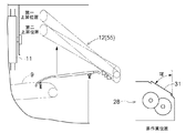
本発明は、刈取穀稈を挟持搬送するフィードチェーンと、扱胴を有すると共にフィードチェーンによって搬送される刈取穀稈を脱穀処理する脱穀装置と、脱穀装置の後側に連設されると共にフィードチェーンから脱穀処理後の排藁を受け取って後方へ挟持搬送する排藁搬送装置と、排藁搬送装置の搬送終端側部位の下方に設けられると共に排藁搬送装置によって搬送された排藁を切断処理する排藁切断装置と、が備えられたコンバインに関する。   The present invention relates to a feed chain for holding and transporting cutting grain gutters, a threshing device for threshing a cutting grain grit that has a threshing cylinder and is transported by the feed chain, and a feed chain connected to the rear side of the threshing equipment. The waste transport device receives the waste after the threshing treatment from behind and sandwiches and transports it backward, and is disposed under the transport end side portion of the waste transport device and cuts the waste transported by the waste transport device And an exhaust cutting device.

上記のようなコンバインとして、例えば、特許文献1に記載のコンバインが既に知られている。特許文献1に記載のコンバインには、刈取穀稈を挟持搬送するフィードチェーン(文献では「脱穀フィードチェン〔38〕」)と、扱胴を有すると共にフィードチェーンによって搬送される刈取穀稈を脱穀処理する脱穀装置(文献では「脱穀装置〔17〕」)と、脱穀装置の後側に連設されると共にフィードチェーンから脱穀処理後の排藁を受け取って後方へ挟持搬送する排藁搬送装置(文献では「排藁搬送装置〔23〕」)と、排藁搬送装置の搬送終端側部位の下方に設けられると共に排藁搬送装置によって搬送された排藁を切断処理する排藁切断装置(文献では「後処理装置〔22〕」)と、が備えられている。排藁切断装置は、左右一端部側で上下方向に延びる揺動軸心(文献では「Y軸」)周りにおいて、排藁搬送装置の搬送終端側部位の下方に位置する作業位置と、排藁搬送装置の搬送終端側部位の下方から離れて位置する非作業位置とに亘って揺動可能である。   For example, a combine described in Patent Document 1 is already known as a combine as described above. In the combine described in Patent Document 1, a feed chain (in the literature, "threshing feed chain [38]") for holding and transporting cut grain pods, and a cut grain pod having a threshing cylinder and transported by the feed chain are subjected to threshing processing A threshing device (in the literature, “threshing device [17]”), and a waste transfer device (document) which is connected to the rear side of the threshing device and receives the waste after threshing treatment from the feed chain In the “Excavator / Transporter [23]”, an exhaust / disruption device (in the literature, provided under the transport end side of the eliminator / transporter and for processing the excrement transported by the eliminator / transporter) And a post-processing device [22] ". The displacement cutting device has a working position located below the transport end side portion of the displacement conveying device around a swing axis ("Y axis" in the literature) extending vertically in the left and right end portions, It is swingable over a non-working position located away from below the end of transport end of the transport device.

特許文献2には、排藁搬送装置(文献では「排藁搬送装置〔15〕」)を平面視で排藁搬送装置の搬送終端側ほど機体左右方向の一方側に位置するように傾斜する状態で支持すると共に機体左右方向の一方側で機体前後方向に延びる揺動軸心(文献では「回動軸〔45〕」)周りで上下揺動可能な排藁フレーム(文献では「株元側支持フレーム〔31〕」)が備えられたコンバインが開示されている。   According to Patent Document 2, the waste transport device (in the literature, "the waste transport device [15]") is inclined to be positioned on one side in the left-right direction of the machine toward the transport end of the waste transport device in plan view And a rocking frame which can be rocked up and down around a rocking axis ("Pivot axis [45]" in the literature) which extends in the longitudinal direction of the machine on one side in the left-right direction of the machine A combine equipped with a frame [31] ") is disclosed.

特開2008−295395号公報JP 2008-295395 A 特開2012−50339号公報JP, 2012-50339, A

ここで、排藁フレームが上方に揺動されるのに伴って、排藁搬送装置の搬送終端側部位が下がることになり、排藁細断装置の搬送終端側部位の位置は、排藁フレームの上昇位置が高くなるほど低くなる。このため、排藁フレームが比較的高い上昇位置まで上昇している状態で、排藁切断装置を作業位置と非作業位置とに切り替えようとすると、排藁切断装置が排藁搬送装置の搬送終端側部位に接触する虞がある。   Here, as the discharge frame is swung upward, the transfer end side portion of the discharge transfer device falls, and the position of the transfer end side portion of the discharge shredding device is the discharge frame The lower the rise position of the For this reason, when the displacement cutting device is to be switched between the working position and the non-working position in a state where the displacement frame is lifted to a relatively high raised position, the displacement cutting device is the transfer end of the displacement conveyance device. There is a risk of touching the side part.

ところで、排藁搬送装置の設置位置を上側に移動したり、あるいは、排藁切断装置の設置位置を下側に移動したりすることにより、排藁搬送装置と排藁切断装置との上下間隔を広げて、上記のような接触を回避するという考え方もある。しかし、排藁搬送装置及び排藁切断装置の設置位置を単純に移動するのは、フィードチェーンと排藁搬送装置との間の排藁の受け渡しや、排藁搬送装置から排藁切断装置への排藁の供給を良好に行う点から得策ではない。   By the way, by moving the installation position of the discharge conveying apparatus upward or moving the installation position of the discharge cutting apparatus downward, the vertical distance between the discharge conveying apparatus and the discharge cutting apparatus There is also a concept of spreading and avoiding the above-mentioned contact. However, simply moving the installation position of the discharge conveying device and the discharge cutting device requires delivery of discharge between the feed chain and the discharge conveying device, or from the discharge conveying device to the discharge cutting device. It is not a good idea in terms of providing a good supply of waste.

上記状況に鑑み、排藁搬送装置及び排藁切断装置の設置位置を適正に保ちながら、排藁フレームが上昇している状態で、排藁切断装置を作業位置と非作業位置とに切り替える際に、排藁切断装置が排藁搬送装置の搬送終端側部位に接触する事態を回避可能なコンバインが要望されている。   In view of the above situation, when switching the exhaust cutting device between the working position and the non-working position in a state where the exhaust frame is elevated while properly maintaining the installation positions of the exhaust conveying device and the exhaust cutting device There is a demand for a combine that can avoid the situation in which the exhaust cutting device comes in contact with the delivery end side portion of the exhaust conveying device.

本発明の特徴は、
刈取穀稈を挟持搬送するフィードチェーンと、
扱胴を有すると共に前記フィードチェーンによって搬送される刈取穀稈を脱穀処理する脱穀装置と、
前記脱穀装置の後側に連設されると共に前記フィードチェーンから脱穀処理後の排藁を受け取って後方へ挟持搬送する排藁搬送装置と、
前記排藁搬送装置の搬送終端側部位の下方に設けられると共に前記排藁搬送装置によって搬送された排藁を切断処理する排藁切断装置と、が備えられたコンバインであって、
前記排藁切断装置は、左右一端部側で上下方向に延びる揺動軸心周りにおいて、前記排藁搬送装置の搬送終端側部位の下方に位置する作業位置と、前記排藁搬送装置の搬送終端側部位の下方から離れて位置する非作業位置とに亘って揺動可能であり、
前記排藁搬送装置を平面視で前記排藁搬送装置の搬送終端側ほど機体左右方向の一方側に位置するように傾斜する状態で支持すると共に機体左右方向の前記一方側で機体前後方向に延びる揺動軸心周りで上下揺動可能な排藁フレームが備えられ、
前記排藁フレームの上昇限界として、少なくとも、第一上昇位置と、前記第一上昇位置よりも低い第二上昇位置と、が設定され、
前記排藁フレームが前記第二上昇位置まで上昇している状態では、前記排藁切断装置を前記作業位置と前記非作業位置とに切り替え可能であり、
前記排藁フレームが前記第一上昇位置まで上昇している状態では、前記排藁切断装置を前記作業位置と前記非作業位置とに切り替え不可能であることにある。
The features of the present invention are:
A feed chain for holding and transporting a reaper
A threshing device having a threshing cylinder and threshing a reaping cropping grain carried by the feed chain;
A waste transport device which is connected to the rear side of the threshing device and receives the waste after threshing treatment from the feed chain and nips and transports it backward;
And a drainage / cutting device provided under the conveyance end side portion of the drainage / conveying device and cutting the drainage conveyed by the drainage / conveying device,
The displacement cutting device has a work position located below the transport end side portion of the displacement and transport device around a swing axis extending vertically in the left and right end portions, and the transport end of the displacement and transport device Swingable over a non-working position located away from below the side part,
The exhaust transport device is supported in an inclined state so as to be positioned on one side in the left-right direction of the machine toward the transport end side of the discharge transport device in plan view and extends in the front-rear direction on the one side in the left-right direction A displacement frame is provided which can be pivoted up and down around the pivot axis,
As a rising limit of the displacement frame, at least a first rising position and a second rising position lower than the first rising position are set.
In the state where the displacement frame is raised to the second raised position, the displacement / cutting device can be switched between the working position and the non-working position,
When the displacement frame is raised to the first raised position, the displacement / cutting device can not be switched between the working position and the non-working position.

本特徴構成によれば、排藁フレームが比較的高い第一上昇位置まで上昇している状態では、排藁切断装置が作業位置と非作業位置とに切り替えられることがない。これにより、排藁フレームが上昇している状態で、排藁切断装置を作業位置と非作業位置とに切り替える際に、排藁切断装置が排藁搬送装置の搬送終端側部位に接触する事態を回避することができる。また、排藁搬送装置の設置位置や排藁切断装置の設置位置の移動を伴わないため、排藁搬送装置及び排藁切断装置の設置位置を適正に保つことができる。   According to this feature configuration, in the state in which the displacement frame is raised to the relatively high first rising position, the displacement cutting device is not switched to the working position and the non-working position. As a result, when the displacement cutting device is switched between the working position and the non-working position in a state where the displacement frame is lifted, a situation in which the displacement cutting device contacts the conveyance end side portion of the displacement conveyance device It can be avoided. Moreover, since the movement of the installation position of the discharge conveyance apparatus and the installation position of the discharge cutting apparatus is not involved, the installation positions of the discharge conveyance apparatus and the discharge cutting apparatus can be properly maintained.

さらに、本発明において、
前記排藁切断装置の前記作業位置から前記非作業位置側への揺動と、前記排藁切断装置の前記非作業位置から前記作業位置側への揺動とを規制するロック機構が備えられていると好適である。
Furthermore, in the present invention,
A lock mechanism is provided which restricts the swinging of the displacement cutting device from the working position to the non-working position and the swinging of the displacement cutting device from the non-working position to the working position. Is preferable.

本特徴構成によれば、ロック機構という機械的な手段により、排藁フレームが第一上昇位置まで上昇している状態で、排藁切断装置が作業位置と非作業位置とに切り替わらないように確実にすることができる。   According to this feature configuration, the mechanical means of the lock mechanism ensures that the drainage cutting device does not switch between the working position and the non-working position while the drainage frame is raised to the first raised position. Can be

さらに、本発明において、
前記排藁フレームの上昇に連動して前記ロック機構が前記排藁切断装置の揺動を規制するように、前記排藁フレームの上昇動作に前記ロック機構の規制動作を連動させる連動機構が備えられていると好適である。
Furthermore, in the present invention,
An interlocking mechanism is provided which interlocks the restraining operation of the lock mechanism with the elevating operation of the eliminator frame so that the lock mechanism restraining the swing of the eliminator cutting device interlockingly with the elevating of the eliminator frame Is preferable.

本特徴構成によれば、排藁フレームが上昇すると、排藁切断装置の揺動が自動的に規制されることになるため、排藁フレームが第一上昇位置まで上昇している状態で、排藁切断装置の揺動が規制されていない事態を回避することができる。   According to this feature configuration, when the displacement frame is lifted, the swing of the displacement and cutting device is automatically restricted. Therefore, the displacement frame is lifted up to the first raised position. It is possible to avoid a situation in which the swinging of the scissors cutting device is not restricted.

さらに、本発明において、
前記ロック機構は、前記排藁切断装置の揺動を規制する状態において、前記排藁切断装置が一定角度範囲だけ揺動するのを許容すると好適である。
Furthermore, in the present invention,
It is preferable that the locking mechanism allows the displacement and cutting device to swing by a predetermined angle range in a state in which the swing and cutting of the displacement and cutting device is regulated.

本特徴構成によれば、排藁切断装置が作業位置又は非作業位置に位置している状態において、ロック機構による規制を解除する手間を要することなく、排藁切断装置を非作業位置側又は作業位置側に少しだけ揺動させることができる。   According to the present feature configuration, in the state where the exhaust cutting device is located at the working position or the non-working position, the exhaust cutting device can be at the non-working position side or at the working position without requiring an effort It can be rocked slightly to the position side.

さらに、本発明において、
前記排藁切断装置の揺動角度を検出する角度検出センサが備えられ、
前記角度検出センサは、前記排藁切断装置を揺動可能に支持する支持部に設けられていると好適である。
Furthermore, in the present invention,
An angle detection sensor for detecting a swing angle of the displacement cutting device is provided.
It is preferable that the angle detection sensor be provided on a support portion that swingably supports the displacement cutting device.

本特徴構成によれば、角度検出センサが排藁切断装置の揺動軸心の近くの位置で排藁切断装置の揺動角度を精度良く検出することができる。   According to this feature configuration, the angle detection sensor can accurately detect the swing angle of the displacement cutting device at a position near the swing axis of the displacement cutting device.

さらに、本発明において、
前記角度検出センサが取り付けられるブラケットが備えられ、
前記角度検出センサは、揺動式の検出アームを有し、
前記ブラケットに、前記検出アームが初期位置から検出範囲外に揺動しないように前記検出アームの揺動を阻止するストッパが設けられていると好適である。
Furthermore, in the present invention,
A bracket on which the angle detection sensor is mounted;
The angle detection sensor has a rocking detection arm,
Preferably, the bracket is provided with a stopper that prevents the detection arm from swinging so that the detection arm does not swing out of the detection range from the initial position.

本特徴構成によれば、ブラケットを利用して、ストッパを容易に設けることができる。また、排藁切断装置を取り外したとしてもストッパが機体側に残ることになり、これにより、検出アームの揺動をストッパによって阻止することができる。   According to this feature configuration, the stopper can be easily provided using the bracket. In addition, even if the exhaust cutting device is removed, the stopper remains on the machine body side, whereby the swing of the detection arm can be blocked by the stopper.

さらに、本発明において、
前記排藁フレームが前記第一上昇位置まで上昇している状態において、前記排藁切断装置を前記作業位置と前記非作業位置とに切り替えようとすると警報を発する警報部が備えられていると好適である。
Furthermore, in the present invention,
It is preferable that an alarm unit is provided that issues an alarm when the displacement / cutting device is to be switched between the working position and the non-working position in a state where the displacement frame is raised to the first raised position. It is.

本特徴構成によれば、警報が発せられることにより、排藁フレームが第一上昇位置まで上昇している状態で、排藁切断装置を作業位置と非作業位置とに切り替えようとしていることを、作業者に知らしめることができる。   According to this feature configuration, when the discharge frame is raised to the first raised position, the discharge cutting device is to be switched between the working position and the non-working position by issuing an alarm. It can be informed to the workers.

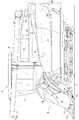
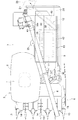
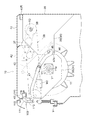
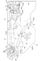
自脱型コンバインを示す左側面図である。It is a left view which shows a self removal type combine. 自脱型コンバインを示す平面図である。It is a top view which shows a self removal type combine. 脱穀装置を示す左側面図である。It is a left side view showing a threshing device. 扱胴フレームを下降させた状態の脱穀装置を示す背面図である。It is a rear view which shows the threshing apparatus of the state which lowered the threshing drum frame. 扱胴フレームを上昇させた状態の脱穀装置を示す背面図である。It is a rear view which shows the threshing apparatus of the state which raised the threshing drum frame. 脱穀装置の後部及び排藁搬送装置を示す平面図である。It is a top view which shows the rear part of a threshing apparatus, and a displacement delivery apparatus. 扱胴フレーム及び排藁フレームを下降させた状態における脱穀装置の後部及び排藁搬送装置を示す左側面図である。It is a left view which shows the rear of a threshing apparatus in the state to which the threshing body flame | frame and the displacement frame were made to descend | fall, and a displacement transfer apparatus. 扱胴フレーム及び排藁フレームを上昇させた状態における脱穀装置の後部及び排藁搬送装置を示す左側面図である。It is a left view which shows the rear of a threshing apparatus in the state which raised the threshing-body flame | frame and the displacement frame, and a displacement-delivery apparatus. 扱胴フレーム及び排藁フレームを下降させた状態における脱穀装置を示す背面図である。It is a rear view which shows the threshing apparatus in the state which lowered the threshing drum frame and the displacement frame. 排藁フレーム及び扱胴フレームを上昇させた状態における脱穀装置を示す背面図である。It is a rear view which shows the threshing apparatus in the state which raised the displacement frame and the threshing drum frame. 排藁フレームが下降位置に位置する状態の排藁搬送装置を示す背面図である。It is a rear view which shows the displacement-delivery apparatus in the state in which a displacement frame is located in a descent | fall position. 排藁フレームを上昇させた状態の排藁搬送装置を示す背面図である。It is a rear view which shows the displacement conveying apparatus of the state which raised the displacement frame. 扱胴フレーム、排藁フレーム及び後部フレームを示す分解斜視図である。It is an exploded perspective view showing a threshing drum frame, a displacement frame and a rear frame. 排藁フレームの基端側の構造を示す分解斜視図である。It is a disassembled perspective view which shows the structure of the proximal end of a displacement frame. 排藁搬送装置及び排藁切断装置を示す背面図である。It is a rear view which shows a discharge conveyance apparatus and a discharge cutting device. ロック機構及び連動機構を示す分解斜視図である。It is an exploded perspective view showing a lock mechanism and an interlocking mechanism. 排藁フレームが下降位置に位置している状態におけるロック機構及び連動機構を示す平面図である。It is a top view which shows the locking mechanism and interlocking mechanism in the state in which the displacement frame is located in the fall position. 排藁フレームが下降位置に位置している状態におけるロック機構及び連動機構を示す左側面図である。It is a left side view showing a lock mechanism and an interlocking mechanism in the state where a displacement frame is located in a descent position. 排藁フレームが第二上昇位置まで上昇した状態におけるロック機構及び連動機構を示す左側面図である。It is a left view which shows the locking mechanism and interlocking mechanism in the state which the displacement frame lifted to the 2nd raise position. 排藁フレームが第一上昇位置まで上昇した状態におけるロック機構及び連動機構を示す左側面図である。It is a left side view showing a locking mechanism and an interlocking mechanism in the state where the displacement frame was raised to the first raised position. 排藁フレームの位置とロック機構の状態と排藁切断装置の切り替えの可否との関係を示す図である。It is a figure which shows the relationship between the position of a displacement frame, the state of a locking mechanism, and the decision | availability of switching of a displacement cutting device. 排藁フレームが下降位置に位置している状態における排藁切断装置の切り替え態様を示す図である。It is a figure which shows the switching aspect of the displacement cutting apparatus in the state in which the displacement frame is located in the fall position. 排藁フレームが第二上昇位置まで上昇した状態における排藁切断装置の切り替え態様を示す図である。It is a figure which shows the switching aspect of the displacement cutting apparatus in the state which the displacement frame raised to the 2nd raise position. 排藁フレームが第一上昇位置まで上昇した状態における排藁切断装置の切り替え態様を示す図である。It is a figure which shows the switching aspect of the displacement cutting apparatus in the state which the displacement frame raised to the 1st raise position. 規制状態のロック機構であって、排藁切断装置が作業位置に位置している状態を示す平面図である。It is a lock mechanism of a regulation state, and is a top view showing the state where a displacement cutting device is located in a working position. 規制状態のロック機構であって、排藁切断装置が第一ロック位置に位置している状態を示す平面図である。It is a lock mechanism of a regulation state, and a displacement cutting device is a top view showing the state where it is located in the 1st lock position. 規制状態のロック機構であって、排藁切断装置が非作業位置に位置している状態を示す平面図である。It is a lock mechanism of a regulation state, and is a top view showing the state where a displacement cutting device is located in a non-working position. 規制状態のロック機構であって、排藁切断装置が第二ロック位置に位置している状態を示す平面図である。It is a lock mechanism of a regulation state, and is a top view showing the state where a displacement cutting device is located in the 2nd lock position. 排藁切断装置の位置と、ロック機構による排藁切断装置の揺動規制と、警報部による警報との関係とを示す図である。It is a figure which shows the relationship between the position of a displacement cutting device, the rocking | fluctuation control of the displacement cutting device by a locking mechanism, and the warning by an alarm part. 制御ブロックを示す図である。It is a figure which shows a control block. 排藁切断装置の位置と排藁フレームの上昇限界との関係を示す図である。It is a figure which shows the relationship between the position of a displacement cutting apparatus, and the raising limit of a displacement frame. 排藁切断装置の位置と排藁フレームの位置と切り替え板の切り替えの可否との関係を示す図である。It is a figure which shows the relationship between the position of a displacement cutting apparatus, the position of a displacement frame, and the decision | availability of switching of a switching board. 排藁切断装置が作業位置に位置している状態における排藁フレームの上昇限界及び切り替え板の切り替え態様を示す図である。It is a figure which shows the switching limit of the raising limit of a displacement frame, and the switching plate in the state in which the displacement cutting device is located in a working position. 排藁切断装置が非作業位置に位置している状態における排藁フレームの上昇限界及び切り替え板の切り替え態様を示す図である。It is a figure which shows the raising limit of the displacement frame in the state in which the displacement cutting device is located in a non-working position, and the switching aspect of a switching board. 排藁切断装置が中間位置に位置している状態における排藁フレームの上昇限界を示す図である。It is a figure which shows the raising limit of the displacement frame in the state in which the displacement cutting device is located in an intermediate position.

〔コンバインの全体構成〕
図1及び図2には、自脱型コンバインを示している。本コンバインは、機体フレーム1と、機体フレーム1を支持する走行装置2と、を備えている。機体の前部における右側には、運転キャビン3が設けられている。運転キャビン3は、運転者が搭乗する運転部4と、運転部4を覆うキャビン5と、を備えている。運転部4の下方には、エンジン(図示省略)が設けられている。
[Overall configuration of combine]
FIG. 1 and FIG. 2 show a self-eliminating type combine. The combine includes an airframe frame 1 and a traveling device 2 for supporting the airframe frame 1. A driving cabin 3 is provided on the right side at the front of the vehicle. The driving cabin 3 includes a driving unit 4 on which a driver rides, and a cabin 5 that covers the driving unit 4. Below the driving unit 4, an engine (not shown) is provided.

運転キャビン3の前方には、植立穀稈を刈り取る刈取部6が設けられている。運転キャビン3の後方には、穀粒を貯留する穀粒貯留タンク7が設けられている。穀粒貯留タンク7内の穀粒を排出する穀粒排出装置8が設けられている。機体の左側部には、刈取穀稈を挟持搬送するフィードチェーン9が設けられている。穀粒貯留タンク7の左隣には、脱穀装置10が設けられている。脱穀装置10は、扱胴11を有すると共にフィードチェーン9によって搬送される刈取穀稈を脱穀処理する。脱穀装置10の後側には、排藁搬送装置12が連設されている。排藁搬送装置12は、フィードチェーン9から脱穀処理後の排藁を受け取って後方へ挟持搬送する。排藁搬送装置12の搬送終端側部位の下方には、排藁搬送装置12によって搬送された排藁を切断処理する排藁切断装置28が設けられている。   In front of the driving cabin 3, a reaper 6 is provided to reap the cropped rice straw. Behind the driving cabin 3, a grain storage tank 7 for storing grains is provided. A grain discharging device 8 for discharging grains in the grain storage tank 7 is provided. At the left side of the machine body, a feed chain 9 is provided for holding and transporting the reaper. A threshing device 10 is provided on the left side of the grain storage tank 7. The threshing device 10 has a threshing cylinder 11 and threshs the reaping grain carried by the feed chain 9. On the rear side of the threshing device 10, a discharge conveyance device 12 is continuously provided. The waste transport device 12 receives the waste after the threshing process from the feed chain 9 and nips and transports the waste backward. Below the delivery end side portion of the discharge conveyance device 12, a discharge cutting device 28 for cutting the discharge waste transferred by the discharge conveyance device 12 is provided.

刈取部6は、複数刈り仕様(例えば、六条刈り仕様)に構成されている。刈取部6は、複数(例えば、七個)の分草具13と、複数(例えば、六個)の引起装置14と、切断装置15と、搬送装置16と、を備えている。分草具13は、圃場の植立穀稈を分草する。引起装置14は、分草された植立穀稈を引き起こす。切断装置15は、引き起こされた植立穀稈を切断する。搬送装置16は、刈取穀稈を脱穀装置10に向けて後方へ搬送する。   The reaper 6 is configured to have a plurality of cutting specifications (for example, a six-row cutting specification). The reaper 6 includes a plurality of (for example, seven) weighing tools 13, a plurality (for example, six) of raising devices 14, a cutting device 15, and a conveying device 16. The wedging tool 13 disperses the crop of the field. The inducer 14 causes the planted cereals to be divided. The cutting device 15 cuts off the induced cereal grains. The transport device 16 transports the reaper to the threshing device 10 rearward.

〔脱穀装置等〕
図3に示すように、脱穀装置10の上部には、扱室17が形成されている。扱室17には、扱胴11が設けられている。扱胴11は、機体前後方向に延びる回転軸心Y1周りで回転可能である。扱胴11の下方には、受網18が設けられている。扱室17の後方には、塵埃を外部に排出する排塵ファン19が設けられている。
[Threshing equipment etc.]
As shown in FIG. 3, at the upper part of the threshing device 10, a throttling chamber 17 is formed. A threshing cylinder 11 is provided in the throttling chamber 17. The threshing cylinder 11 is rotatable around a rotational axis Y1 extending in the longitudinal direction of the vehicle. A net 18 is provided below the threshing drum 11. At the rear of the handling chamber 17, a dust collecting fan 19 for discharging dust to the outside is provided.

脱穀装置10の下部には、選別対象物を揺動選別する揺動選別装置20、揺動選別装置20に選別風を送風する唐箕21、一番物の穀粒(単粒化穀粒等)を回収する一番回収部22、二番物の穀粒(枝梗付き穀粒等)を回収する二番回収部23等が設けられている。   At the lower part of the threshing apparatus 10, a rocking and sorting apparatus 20 for rocking and sorting the objects to be sorted, a tile 21 for blowing the selection wind to the rocking and sorting apparatus 20, grain of the first item (grains etc.) No. 2 collection part 23 which collects the first collection part 22 which collect | recovers, and the grain (grains etc. with a branch stem) of a second thing are provided.

一番回収部22には、一番物の穀粒を右方へ搬送する一番スクリュ24が設けられている。一番スクリュ24の右端部には、一番物の穀粒を穀粒貯留タンク7に揚穀搬送する揚穀装置25が連動連結されている。   The first recovery section 22 is provided with a first screw 24 for conveying the grain of the first object to the right. At the right end portion of the first screw 24, a threshing device 25 for throttling and transporting the grain of the first product to the grain storage tank 7 is interlocked and coupled.

二番回収部23には、二番物の穀粒を右方へ搬送する二番スクリュ26が設けられている。二番スクリュ26の右端部には、二番物の穀粒を揺動選別装置20に還元する二番還元装置27が連動連結されている。   The second collecting portion 23 is provided with a second screw 26 for conveying a second grain to the right. At the right end of the second screw 26, a second reduction device 27 for reducing the grain of the second shot to the rocking and sorting device 20 is interlocked and connected.

排藁切断装置28は、右端部側で上下方向に延びる揺動軸心Z1周りにおいて、排藁搬送装置12の搬送終端側部位の下方に位置する作業位置と、排藁搬送装置12の搬送終端側部位の下方から離れて位置する非作業位置とに亘って揺動可能である(図2参照)。排藁切断装置28は、排藁を切断するカッタ29と、カッタ29を覆うカバー30と、切り替え板31と、を備えている。カバー30のうちカッタ29の上方に位置する部分には、排藁が投入される投入口30aが形成されている。カバー30の上部における左側壁と右側壁とに亘って、機体左右方向に延びる横フレーム32が設けられている。   The displacement cutting device 28 has a work position located below the conveyance end side portion of the displacement conveyance device 12 around the swing axis Z1 extending in the vertical direction on the right end side, and the conveyance end of the displacement conveyance device 12 It is pivotable over a non-working position which is located away from below the side part (see FIG. 2). The drainage and cutting device 28 includes a cutter 29 for cutting the drainage, a cover 30 that covers the cutter 29, and a switching plate 31. A portion of the cover 30 located above the cutter 29 is formed with an insertion port 30 a into which the drainage is inserted. A transverse frame 32 extending in the left-right direction of the vehicle body is provided across the left side wall and the right side wall at the top of the cover 30.

切り替え板31は、投入口30aを開く切断位置と投入口30aを閉じる非切断位置とに切り替え可能であり、機体左右方向に延びる揺動軸心周りで上昇側の切断位置と下降側の非切断位置とに亘って揺動開閉可能である。排藁切断装置28の右側部には、切り替え板31を揺動駆動するモータM1(図30参照)が設けられている。切り替え板31が開いた状態(切断位置の状態)では、排藁搬送装置12によって搬送された排藁が投入口30aに投入されてカッタ29によって切断される。切り替え板31が閉じた状態(非切断位置の状態)では、排藁搬送装置12によって搬送された排藁が切り替え板31の上面を滑って地面に落下する。   The switching plate 31 can be switched between a cutting position for opening the inlet 30a and a non-cutting position for closing the inlet 30a, and the cutting position on the rising side and the non-cutting on the lowering side around the swing axis extending in the left and right direction of the machine. It can swing open and close over the position. A motor M1 (see FIG. 30) for swinging and driving the switching plate 31 is provided on the right side of the displacement cutting device. In the state where the switching plate 31 is open (the state of the cutting position), the drainage transported by the drainage conveying device 12 is inserted into the insertion port 30 a and cut by the cutter 29. In the state where the switching plate 31 is closed (the state of the non-cutting position), the drainage transported by the drainage conveyance device 12 slips on the upper surface of the switching plate 31 and falls to the ground.

図3から図5に示すように、扱室17における前端部及び後端部には、夫々、壁部34が設けられている。前側の壁部34は、扱室17の前壁部を構成している。後側の壁部34は、扱室17の後壁部を構成している。壁部34は、可動壁35と、固定壁36と、を備えている。可動壁35には、扱胴11が扱胴軸11aを介して回転可能に支持されている。可動壁35と固定壁36とに亘って、これらを連結する連結アーム37が設けられている。可動壁35は、連結アーム37を介して機体前後方向に延びる揺動軸心Y2周りで上下揺動可能に固定壁36に支持されている。前側の固定壁36と後側の固定壁36とに亘って、前記エンジンの動力が伝達される伝動軸38が設けられている。脱穀装置10の左右両側部には、夫々、機体前後方向に延びる前後向きフレーム40L・40Rが設けられている。   As shown in FIGS. 3 to 5, wall portions 34 are provided at the front end portion and the rear end portion of the handling chamber 17, respectively. The front wall portion 34 constitutes a front wall portion of the processing chamber 17. The rear wall 34 constitutes a rear wall of the handling room 17. The wall portion 34 includes a movable wall 35 and a fixed wall 36. The threshing drum 11 is rotatably supported by the movable wall 35 via the threshing drum shaft 11 a. A connecting arm 37 connecting the movable wall 35 and the fixed wall 36 is provided. The movable wall 35 is supported by the fixed wall 36 so as to be vertically swingable around a swing axis Y2 extending in the longitudinal direction of the machine via the connection arm 37. A transmission shaft 38 to which the power of the engine is transmitted is provided across the front fixed wall 36 and the rear fixed wall 36. At the left and right sides of the threshing device 10, front and rear facing frames 40L and 40R extending in the longitudinal direction of the vehicle are provided.

扱胴11を上方から覆う扱胴カバー42が設けられている。扱胴カバー42の右隣には、右上部カバー43が設けられている。右上部カバー43は、機体前後方向に延びる揺動軸心周りで上下揺動可能に右側の前後向きフレーム40Rに支持されている。   A threshing cylinder cover 42 covering the throttling cylinder 11 from above is provided. An upper right cover 43 is provided on the right of the threshing drum cover 42. The right upper cover 43 is supported by the right front-rear direction frame 40R so as to be swingable up and down around a swing axis extending in the longitudinal direction of the machine body.

扱胴11を支持すると共に揺動軸心Y2周り上下揺動可能な扱胴フレーム44が設けられている。扱胴フレーム44は、前後一対の可動壁35と、左側の前後向きフレーム40Lと、を備えている。扱胴フレーム44には、扱胴カバー42も支持されている。   A threshing drum frame 44 is provided which supports the threshing drum 11 and can be pivoted up and down around a pivot axis Y2. The threshing drum frame 44 is provided with a pair of front and rear movable walls 35 and a left and front facing frame 40L. The threshing drum cover 44 is also supported by the threshing drum frame 44.

扱胴フレーム44を上下揺動させるシリンダ45が設けられている。シリンダ45は、後側の可動壁35と後側の固定壁36とに亘って設けられている。本実施形態では、シリンダ45は、電動シリンダによって構成されている。   A cylinder 45 for swinging the threshing drum frame 44 up and down is provided. The cylinder 45 is provided across the movable wall 35 on the rear side and the fixed wall 36 on the rear side. In the present embodiment, the cylinder 45 is configured by an electric cylinder.

扱胴11を、脱穀処理を行う脱穀処理位置に位置保持する扱胴ロック機構46が設けられている。扱胴ロック機構46は、前後一対のフックプレート47と、前後一対の扱胴フックピン48と、を備えている。前側の壁部34及び後側の壁部34の夫々に、フックプレート47が機体前後方向に延びる揺動軸心Y3周りで揺動可能に支持されている。フックプレート47の先端部には、扱胴フックピン48に係合可能なフック部47aが設けられている。フック部47aが扱胴フックピン48に係合することにより、扱胴11が脱穀処理位置に位置保持される。扱胴フックピン48に対するフック部47aの係合が解除されることにより、扱胴フレーム44と共に扱胴11がシリンダ45によって上方に揺動される。前後一対のフックプレート47を揺動駆動するモータM2が、後側の壁部34の後面に支持されている。モータM2によって、前後一対のフックプレート47が係合側及び係合解除側に揺動される。   A threshing drum lock mechanism 46 is provided which holds the threshing drum 11 at a threshing processing position where threshing processing is performed. The threshing drum lock mechanism 46 includes a pair of front and rear hook plates 47 and a pair of threshing drum hook pins 48. A hook plate 47 is supported swingably around a swing axis Y3 extending in the longitudinal direction of the machine on the front wall 34 and the rear wall 34 respectively. At the tip of the hook plate 47, a hook portion 47a engageable with the threshing drum hook pin 48 is provided. The hook portion 47a engages with the threshing drum hook pin 48 to hold the threshing drum 11 in the threshing processing position. By releasing the engagement of the hook portion 47 a with the threshing drum hook pin 48, the throttling barrel 11 is pivoted upward by the cylinder 45 together with the throttling barrel frame 44. A motor M2 that swings and drives a pair of front and rear hook plates 47 is supported on the rear surface of the rear wall 34. The motor M2 swings the pair of front and rear hook plates 47 to the engagement side and the engagement release side.

図6及び図7に示すように、脱穀装置10の左側部における後上部には、後部フレーム41が設けられている。後部フレーム41は、側面視で脱穀装置10の後部から後方に突出する略U字形状に形成されている。後部フレーム41は、丸パイプによって構成されている。   As shown in FIG. 6 and FIG. 7, a rear frame 41 is provided at the rear upper part of the left side of the threshing apparatus 10. The rear frame 41 is formed in a substantially U-shape projecting rearward from the rear of the threshing device 10 in a side view. The rear frame 41 is constituted by a round pipe.

後部フレーム41のうち上側部分41aと下側部分41bとの間を、排藁搬送装置12によって搬送される排藁STが通過する。後部フレーム41の後部には、平面視で機体横外側(左側)に折れ曲がる折れ曲り部41cが形成されている。   Between the upper portion 41a and the lower portion 41b of the rear frame 41, the drainage ST transported by the drainage transport device 12 passes. At a rear portion of the rear frame 41, a bent portion 41c is formed which is bent to the lateral side (left side) of the vehicle in a plan view.

ここで、後部フレーム41の後部が平面視で後方に向かって真っ直ぐ延びている場合(図6に示す二点鎖線で描かれた後部フレーム41を参照)、排藁搬送装置12によって搬送される排藁STが稈長の長い穀稈(長稈)の排藁であると、排藁STの株元が後部フレーム41の後端部における縦部分に接触して搬送の抵抗となり、排藁STの詰りが発生する虞がある。   Here, when the rear portion of the rear frame 41 extends straight rearward in plan view (see the rear frame 41 drawn by a two-dot chain line shown in FIG. 6), the discharge carried by the discharge conveyance device 12 If 藁 ST is the displacement of a long grain stalk (long stalk), the stock origin of the stalk ST contacts the longitudinal portion in the rear end portion of the rear frame 41 to serve as a transport resistance, and clogging of the stalk ST May occur.

しかし、上記構成によれば、後部フレーム41の後部に、折れ曲り部41cが形成されていることにより、後部フレーム41の後端部における縦部分41dと排藁搬送装置12(株元搬送装置49)との間隔が長くなる。これにより、長稈の排藁STであっても排藁STの株元が縦部分41dに接触することなく、排藁STを排藁搬送装置12によって搬送することができる。また、後部フレーム41を後方に延長することにより、前記間隔を長くするものではないため、機体の前後長が長くなることもない。   However, according to the above configuration, since the bent portion 41 c is formed at the rear of the rear frame 41, the vertical portion 41 d at the rear end of the rear frame 41 and the discharge conveyance device 12 (the stock conveyance device 49 ) And the interval will be longer. Thereby, even if it is a long tubal drainage ST, the drainage ST can be conveyed by the drainage / conveying device 12 without the stock origin of the drainage ST contacting the vertical portion 41d. Further, by extending the rear frame 41 rearward, the space is not increased, so that the longitudinal length of the vehicle does not increase.

〔排藁搬送装置〕
図6及び図7に示すように、排藁搬送装置12は、平面視で排藁搬送装置12の搬送終端側ほど機体左右方向の一方側(右側)に位置するように傾斜する状態で排藁フレーム55に支持されている。排藁搬送装置12は、排藁の株元側を挟持搬送する株元搬送装置49と、排藁の穂先側を係止搬送する穂先搬送装置50と、を備えている。株元搬送装置49は、突起51a付きの排藁チェーン51と、排藁レール52と、を備えている。排藁レール52は、排藁チェーン51の下方において、排藁チェーン51の下側経路に対向する状態で配置されている。株元搬送装置49の搬送終端部には、排藁チェーン51を案内する一対のガイド板53が設けられている。穂先搬送装置50は、タイン54a付きの排藁穂先チェーン54を備えている。
[Exclusion Transporter]
As shown in FIG. 6 and FIG. 7, the waste transport device 12 is discharged in a state where it is inclined so as to be positioned on one side (right side) in the left-right direction of the machine in the transport end side of the waste transport device 12 in plan view. It is supported by the frame 55. The discharge conveyance apparatus 12 is provided with a stock origin conveyance apparatus 49 for holding and conveying the stock origin side of the discharge, and a tip conveyance apparatus 50 for holding and conveying the tip side of the discharge. The stock feeding device 49 includes a drainage chain 51 with a protrusion 51 a and a drainage rail 52. The displacement rail 52 is disposed below the displacement chain 51 so as to face the lower path of the displacement chain 51. A pair of guide plates 53 for guiding the discharge chain 51 is provided at the conveyance end of the stock conveyance device 49. The tip conveying device 50 includes a drainage tip chain 54 with a tine 54a.

排藁搬送装置12の排藁搬送空間Sが、後側の壁部34の後方に形成されている。排藁搬送空間Sは、機体前後方向において、排藁フレーム55を跨ぐように形成されている。排藁搬送空間Sは、平面視において、排藁搬送空間Sの前後中途部(傾斜部39aの前端に対応する箇所)で搬送方向下流側ほど右側に位置するように広がっている。伝動軸38と排藁搬送装置12の入力軸(図示省略)とに亘って、伝動軸38の動力を排藁搬送装置12の前記入力軸に伝達するベルト伝動機構58が設けられている。   An exhaust conveyance space S of the exhaust conveyance device 12 is formed at the rear of the rear wall 34. The discharge conveyance space S is formed to straddle the discharge frame 55 in the longitudinal direction of the machine body. The drainage conveyance space S is expanded so as to be positioned on the right in the conveyance direction downstream in the front and rear middle portion (portion corresponding to the front end of the inclined portion 39a) of the drainage conveyance space S in plan view. A belt transmission mechanism 58 for transmitting the power of the transmission shaft 38 to the input shaft of the displacement conveyance device 12 is provided across the transmission shaft 38 and the input shaft (not shown) of the displacement conveyance device 12.

〔排藁フレーム〕
図6から図14に示すように、排藁フレーム55は、排藁搬送装置12を平面視で排藁搬送装置12の搬送終端側ほど機体左右方向の一方側(右側)に位置するように傾斜する状態で支持すると共に機体左右方向の一方側(右側)で機体前後方向に延びる揺動軸心Y2周りで上下揺動可能である。排藁搬送装置12は、排藁フレーム55から取り外し可能であり、前ステー56及び後ステー57を介して排藁フレーム55に吊り下げ支持されている。
[Exclusion frame]
As shown in FIG. 6 to FIG. 14, the displacement frame 55 is inclined so that the displacement conveyance device 12 is positioned on one side (right side) in the left-right direction of the machine toward the conveyance end side of the displacement conveyance device 12 in plan view. It can be rocked up and down around a rocking axis Y2 extending in the longitudinal direction of the machine on one side (right side) of the machine in the lateral direction of the machine. The discharge conveyance device 12 is removable from the discharge frame 55 and is suspended and supported by the discharge frame 55 via the front stay 56 and the rear stay 57.

排藁フレーム55は、枠状に形成されており、基端フレーム部71と、前フレーム部72と、後フレーム部73と、遊端フレーム部74と、を備えている。一本の丸パイプが折り曲げられて、前フレーム部72、後フレーム部73及び遊端フレーム部74が形成されている。前フレーム部72の基端部及び後フレーム部73の基端部は、夫々、後側及び前側に向かって折れ曲がっている。前フレーム部72の基端部と後フレーム部73の基端部との間には、間隔があけられている。   The displacement frame 55 is formed in a frame shape, and includes a proximal end frame portion 71, a front frame portion 72, a rear frame portion 73, and a free end frame portion 74. A single round pipe is bent to form a front frame portion 72, a rear frame portion 73, and a free end frame portion 74. The proximal end of the front frame portion 72 and the proximal end of the rear frame portion 73 are bent toward the rear side and the front side, respectively. A space is provided between the proximal end of the front frame portion 72 and the proximal end of the rear frame portion 73.

基端フレーム部71は、前フレーム部72の基端部と後フレーム部73の基端部とに亘って設けられている。基端フレーム部71は、前フレーム部72の基端部及び後フレーム部73の基端部に対して下側から固定されている。基端フレーム部71は、角パイプによって構成されている。   The proximal end frame portion 71 is provided across the proximal end portion of the front frame portion 72 and the proximal end portion of the rear frame portion 73. The proximal end frame portion 71 is fixed to the proximal end portion of the front frame portion 72 and the proximal end portion of the rear frame portion 73 from the lower side. The proximal end frame portion 71 is constituted by a square pipe.

排藁フレーム55は、支軸76を介して前後一対のステー78に揺動軸心Y2周りで上下揺動可能に支持されている。支軸76は、伝動軸38と同一の揺動軸心Y2上に配置されている。支軸76は、ステー83に固定されている。ステー83は、基端フレーム部71に固定されている。前後一対のステー78は、ブラケット87にボルト固定されている。ブラケット87は、右側の前後向きフレーム40Rの下面に垂設されている。   The displacement frame 55 is supported by the pair of front and rear stays 78 via a support shaft 76 so as to be vertically swingable around a swing axis Y2. The support shaft 76 is disposed on the same swing axis Y2 as the transmission shaft 38. The spindle 76 is fixed to the stay 83. The stay 83 is fixed to the proximal end frame portion 71. The pair of front and rear stays 78 are bolted to the bracket 87. The bracket 87 is vertically provided on the lower surface of the right front-rear direction frame 40R.

排藁フレーム55は、排藁搬送装置12が排藁の搬送を行う下降位置と排藁搬送装置12が排藁の搬送を行わない上昇位置(後述する、第一上昇位置及び第二上昇位置)とに亘って、揺動軸心Y2周りで上下揺動可能である。扱胴フレーム44と排藁フレーム55とを連結解除可能に連結する連結部60が設けられている。扱胴フレーム44と排藁フレーム55とが連結部60によって連結された状態で、扱胴フレーム44と排藁フレーム55とが一体的にシリンダ45によって上下揺動可能である。   The discharge frame 55 has a lowered position at which the discharge and transfer device 12 transports discharges and an elevated position at which the discharge and discharge devices 12 do not transfer discharges (a first raised position and a second raised position described later) It is possible to rock up and down around the rocking axis Y2. A connecting portion 60 is provided for releasably connecting the threshing drum frame 44 and the discharge frame 55. In a state where the threshing drum frame 44 and the discharge frame 55 are connected by the connecting portion 60, the threshing drum frame 44 and the discharge frame 55 can be integrally vertically oscillated by the cylinder 45.

排藁フレーム55の上昇限界として、第一上昇位置(図15に示す第一上昇角度αに対応する上昇位置)と、第一上昇位置よりも低い第二上昇位置(図15に示す第二上昇角度βに対応する上昇位置)と、が設定されている。第一上昇位置は、扱胴11の詰り除去を行うことが可能な位置である。第二上昇位置は、排藁搬送装置12の搬送終端側部位が排藁切断装置28と干渉しない位置であり(図8参照)、排藁搬送装置12の詰り除去を行うことが可能な位置である。   The first lifting position (the lifting position corresponding to the first lifting angle α shown in FIG. 15) and the second lifting position lower than the first lifting position (the second lifting position shown in FIG. 15) An ascending position corresponding to the angle β) is set. The first raised position is a position at which clogging removal of the threshing cylinder 11 can be performed. The second elevation position is a position where the conveyance end side portion of the discharge conveying apparatus 12 does not interfere with the discharge cutting apparatus 28 (refer to FIG. 8), and is a position where clogging removal of the discharge conveying apparatus 12 can be performed is there.

連結部60は、左側の前後向きフレーム40Lに固定された第一ブラケット61と、遊端フレーム部74に固定された第二ブラケット62と、第一ブラケット61と第二ブラケット62とに亘ってこれらを連結する連結プレート63と、を備えている。連結プレート63は、第一ブラケット61及び第二ブラケット62に夫々ボルト固定されている。   The connecting portion 60 includes a first bracket 61 fixed to the left front-rear direction frame 40L, a second bracket 62 fixed to the free end frame portion 74, and the first bracket 61 and the second bracket 62. And a connecting plate 63 for connecting the The connection plate 63 is bolted to the first bracket 61 and the second bracket 62, respectively.

〔排藁フレーム用の内側ロック機構〕
図9から図14に示すように、排藁フレーム55が下降位置に位置する状態で、排藁フレーム55の基端側部位を右側の前後向きフレーム40Rに位置保持する内側ロック機構93が設けられている。内側ロック機構93は、内側フック94と、内側フックピン95と、を備えている。内側フック94は、基端フレーム部71に支持されている。内側フックピン95は、右側の前後向きフレーム40Rに支持されている。
[Inner locking mechanism for the displacement frame]
As shown in FIGS. 9 to 14, an inner locking mechanism 93 is provided for holding the proximal end portion of the discharge frame 55 at the right front-rear direction frame 40R with the discharge frame 55 in the lowered position. ing. The inner locking mechanism 93 comprises an inner hook 94 and an inner hook pin 95. The inner hook 94 is supported by the proximal frame portion 71. The inner hook pin 95 is supported by the right front-rear direction frame 40R.

図11に示すように、排藁フレーム55が下降位置側に揺動するのに追従して内側フック94が内側フックピン95に係合することにより、排藁フレーム55の基端側部位が内側ロック機構93によって右側の前後向きフレーム40Rに位置保持される。そして、図12に示すように、排藁フレーム55が上昇位置側に揺動するのに追従して内側フックピン95に対する内側フック94の係合が解除されることにより、内側ロック機構93による位置保持が解除される。   As shown in FIG. 11, the proximal end side portion of the discharge frame 55 is locked by the inner hook 94 engaging with the inner hook pin 95 following the swinging of the discharge frame 55 to the lowered position side. The position is held by the mechanism 93 on the right front-rear direction frame 40R. Then, as shown in FIG. 12, as the displacement frame 55 swings to the raised position side and the engagement of the inner hook 94 with the inner hook pin 95 is released, the position holding by the inner lock mechanism 93 is performed. Is released.

〔扱胴フレーム用の外側ロック機構〕
図6から図10及び図13に示すように、扱胴フレーム44が下降位置に位置する状態で、左側の前後向きフレーム40Lを後部フレーム41に位置保持する外側ロック機構96が設けられている。外側ロック機構96は、外側フック97と、外側フックピン98と、を備えている。外側フック97は、左側の前後向きフレーム40Lに支持されている。外側フックピン98は、後部フレーム41に支持されている。
[Outside lock mechanism for the threshing drum frame]
As shown in FIG. 6 to FIG. 10 and FIG. 13, an outer side locking mechanism 96 is provided for holding the left front-to-rear direction frame 40L in position with the rear frame 41 with the throttling barrel frame 44 in the lowered position. The outer locking mechanism 96 comprises an outer hook 97 and an outer hook pin 98. The outer hook 97 is supported by the left front-rear direction frame 40L. The outer hook pin 98 is supported by the rear frame 41.

扱胴ロック機構46(後側のフックプレート47)と、外側ロック機構96(外側フック97)とを連動連結するリンク機構109が設けられている。リンク機構109は、第一リンクアーム110と、第二リンクアーム111と、リンクロッド112と、を備えている。第一リンクアーム110は、後側のフックプレート47の基端部に相対揺動可能に連結されている。第一リンクアーム110と第二リンクアーム111とは、相対揺動可能に連結されている。リンクロッド112の前端部には、第二リンクアーム111が相対揺動不能に連結されている。リンクロッド112の後端部には、外側フック97が相対揺動不能に連結されている。   A link mechanism 109 is provided which interlocks and links the threshing drum lock mechanism 46 (the rear hook plate 47) and the outer lock mechanism 96 (the outer hook 97). The link mechanism 109 includes a first link arm 110, a second link arm 111, and a link rod 112. The first link arm 110 is connected to the proximal end of the rear hook plate 47 so as to be relatively swingable. The first link arm 110 and the second link arm 111 are connected so as to be relatively swingable. The second link arm 111 is connected to the front end of the link rod 112 so as not to allow relative swing. An outer hook 97 is connected to the rear end of the link rod 112 so as not to allow relative swing.

図9に示すように、モータM2によって前後一対のフックプレート47が係合側に揺動されることにより、フックプレート47(フック部47a)が扱胴フックピン48に係合される。そして、後側のフックプレート47の係合側への揺動がリンク機構109を介して外側フック97に伝達されることにより、後側のフックプレート47の係合側への揺動に連動して、外側フック97が係合側に揺動される。こうして、外側フック97が係合状態になることにより、左側の前後向きフレーム40Lが外側ロック機構96によって後部フレーム41に位置保持される。   As shown in FIG. 9, the hook plate 47 (hook portion 47 a) is engaged with the threshing drum hook pin 48 by the pair of front and rear hook plates 47 being pivoted to the engagement side by the motor M 2. Then, the swinging of the rear hook plate 47 to the engagement side is transmitted to the outer hook 97 through the link mechanism 109, thereby interlocking with the swinging of the rear hook plate 47 to the engagement side. Thus, the outer hook 97 is swung to the engagement side. In this way, the left and right front frame 40L is held in position by the outer locking mechanism 96 on the rear frame 41 by the outer hook 97 being engaged.

そして、図10に示すように、モータM2によって前後一対のフックプレート47が係合解除側に揺動されることにより、扱胴フックピン48に対するフックプレート47(フック部47a)の係合が解除される。そして、後側のフックプレート47の係合解除側への揺動がリンク機構109を介して外側フック97に伝達されることにより、後側のフックプレート47の係合解除側への揺動に連動して、外側フック97が係合解除側に揺動される。こうして、外側フック97が係合解除状態になることにより、外側ロック機構96による位置保持が解除される。   Then, as shown in FIG. 10, the motor M2 swings the pair of front and rear hook plates 47 toward the engagement release side, whereby the engagement of the hook plate 47 (hook portion 47a) with the threshing drum hook pin 48 is released. Ru. Then, the swinging of the rear hook plate 47 to the engagement release side is transmitted to the outer hook 97 through the link mechanism 109, whereby the swinging of the rear hook plate 47 to the engagement release side is performed. In conjunction, the outer hook 97 is swung to the disengagement side. Thus, when the outer hook 97 is in the disengaged state, the position holding by the outer locking mechanism 96 is released.

〔排藁切断装置の揺動構造〕
図6、図15から図18に示すように、排藁切断装置28は、揺動軸心Z1周りで揺動可能なように、支柱113に支持されている。支柱113には、上下一対の支軸114が設けられている。支柱113には、支軸114を支持する支持部115が設けられている。
[Swaying structure of displacement cutting device]
As shown in FIG. 6 and FIG. 15 to FIG. 18, the displacement cutting device 28 is supported by the support 113 so as to be swingable around the swing axis Z1. The support column 113 is provided with a pair of upper and lower support shafts 114. The support 113 is provided with a support portion 115 for supporting the support shaft 114.

排藁切断装置28の右側部には、上下方向に延びる円形断面のフレーム116と、上側の支軸114に回転可能な状態で連結されるプレート117と、下側の支軸114に回転可能な状態で連結されるブラケット118と、が設けられている。プレート117は、揺動軸心Z1周りでフレーム116と一体に揺動するように、フレーム116に固定されている。   A frame 116 having a circular cross section extending in the vertical direction, a plate 117 rotatably connected to the upper support shaft 114, and a lower support shaft 114 can be rotated on the right side of the exhaust cutting device 28 And a bracket 118 connected in the state. The plate 117 is fixed to the frame 116 so as to swing integrally with the frame 116 around the swing axis Z1.

排藁切断装置28の揺動軸心Z1周りの揺動角度を検出する角度検出センサ119が設けられている。角度検出センサ119は、ポテンショメータによって構成されている。角度検出センサ119は、揺動式の検出アーム119aを備えている。検出アーム119aは、フレーム116に接触している。   An angle detection sensor 119 is provided for detecting the swing angle of the displacement and cutting device 28 about the swing axis Z1. The angle detection sensor 119 is configured by a potentiometer. The angle detection sensor 119 includes a rocking detection arm 119a. The detection arm 119 a is in contact with the frame 116.

〔排藁切断装置用のロック機構〕
図6、図15から図18に示すように、排藁切断装置28の作業位置から非作業位置側への揺動と、排藁切断装置28の非作業位置から作業位置側への揺動とを規制するロック機構120が設けられている。ロック機構120は、排藁切断装置28の揺動を規制しない非規制状態と、排藁切断装置28の揺動を規制する規制状態とに切り替え可能である。ロック機構120は、プレート117と、カム121と、を備えている。
[Locking mechanism for displacement cutting device]
As shown in FIG. 6 and FIG. 15 to FIG. 18, the swinging of the displacement cutting device 28 from the working position to the non-working position and the swinging of the displacement cutting device 28 from the non-working position to the working position A locking mechanism 120 is provided to regulate the The lock mechanism 120 can be switched between a non-regulating state in which the swinging of the displacement-cutting device 28 is not regulated and a regulated state in which the swinging of the displacement-cutting device 28 is regulated. The lock mechanism 120 includes a plate 117 and a cam 121.

カム121は、機体左右方向に延びる揺動軸心X1周りで揺動可能なように、軸部122に支持されている。軸部122は、上側の支持部115の左側部から左方に突出している。カム121は、軸部122に外嵌された状態でボルト123及び平座金124によって抜け止めされている。   The cam 121 is supported by the shaft portion 122 so as to be swingable around a swing axis X1 extending in the left-right direction of the machine body. The shaft portion 122 protrudes leftward from the left side portion of the upper support portion 115. The cam 121 is prevented from coming off by a bolt 123 and a plain washer 124 in a state of being externally fitted to the shaft portion 122.

カム121を初期位置側に揺動付勢する捩じりバネ125が設けられている。カム121が初期位置に位置する状態で当接するストッパ126が設けられている。捩じりバネ125は、軸部122に外嵌されていると共に、その一端部がカム121に係合され、かつ、その他端部がストッパ126に係合されている。カム121は、捩じりバネ125によって初期位置側に揺動付勢されてストッパ126に当接することにより、初期位置に位置保持されている。   A torsion spring 125 is provided to urge the cam 121 toward the initial position. A stopper 126 is provided to abut in a state where the cam 121 is at the initial position. The torsion spring 125 is externally fitted to the shaft portion 122, and one end thereof is engaged with the cam 121 and the other end is engaged with the stopper 126. The cam 121 is urged toward the initial position by the torsion spring 125 and is held in the initial position by abutting on the stopper 126.

排藁フレーム55の上昇に連動してロック機構120が排藁切断装置28の揺動を規制するように、排藁フレーム55の上昇動作にロック機構120の規制動作を連動させる連動機構127が設けられている。連動機構127は、排藁フレーム55とカム121とに亘るケーブルワイヤ128を備えている。ケーブルワイヤ128は、脱穀装置10の右側壁39のうち、後側ほど右側に位置するように傾斜する傾斜部39aに沿って配策されている。ケーブルワイヤ128は、インナワイヤ128aと、アウタワイヤ128bと、を備えている。インナワイヤ128aのうち排藁フレーム55側の端部は、ステー129に連結されている。ステー129は、ステー130にボルト固定されている。ステー130は、ステー83にボルト固定されている。アウタワイヤ128bのうち排藁フレーム55側の端部は、ステー79に支持されている。ステー79は、後側のステー78にボルト固定されている。インナワイヤ128aのうちカム121側の端部は、カム121に連結されている。アウタワイヤ128bのうちカム121側の端部は、ステー131に支持されている。ステー131は、上側の支持部115の左側部に固定されている。   An interlocking mechanism 127 is provided to interlock the restricting operation of the lock mechanism 120 with the raising operation of the discharge frame 55 so that the lock mechanism 120 restricts the swinging of the discharge cutting device 28 interlocked with the upward movement of the discharge frame 55 It is done. The interlocking mechanism 127 includes a cable wire 128 extending between the displacement frame 55 and the cam 121. The cable wire 128 is routed along an inclined portion 39 a of the right side wall 39 of the threshing apparatus 10 which is inclined so as to be positioned on the right side toward the rear side. The cable wire 128 includes an inner wire 128a and an outer wire 128b. The end of the inner wire 128 a on the side of the discharge frame 55 is connected to the stay 129. The stay 129 is bolted to the stay 130. The stay 130 is bolted to the stay 83. The end of the outer wire 128 b on the side of the discharge frame 55 is supported by the stay 79. The stay 79 is bolted to the rear stay 78. The end of the inner wire 128 a on the cam 121 side is connected to the cam 121. The end of the outer wire 128 b on the cam 121 side is supported by the stay 131. The stay 131 is fixed to the left side portion of the upper support portion 115.

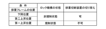
図18に示すように、排藁フレーム55が下降位置に位置している状態では、カム121が初期位置に位置保持されている。図18に示す状態では、プレート117の先端117aの回転軌跡内において、カム121がプレート117の下面よりも下側に位置している。このため、プレート117が揺動軸心Z1周りで回転しても、カム121に当接せず、排藁切断装置28の揺動が規制されない。このように、図21及び図22に示すように、排藁フレーム55が下降位置に位置している状態では、ロック機構120が非規制状態であり、排藁切断装置28を作業位置と非作業位置とに切り替えることができる。   As shown in FIG. 18, in the state where the evacuation frame 55 is in the lowered position, the cam 121 is held in the initial position. In the state shown in FIG. 18, the cam 121 is located below the lower surface of the plate 117 within the rotation trajectory of the tip end 117 a of the plate 117. For this reason, even if the plate 117 rotates around the swing axis Z1, it does not contact the cam 121, and the swing of the displacement cutting device 28 is not restricted. Thus, as shown in FIG. 21 and FIG. 22, when the displacement frame 55 is in the lowered position, the lock mechanism 120 is in the non-restricted state, and the displacement / cutting device 28 is in the working position and not in operation. You can switch to position.

そして、図19に示すように、排藁フレーム55が第二上昇位置まで上昇すると、排藁フレーム55の上昇に連動して、カム121が捩じりバネ125の付勢力に抗してケーブルワイヤ128に引っ張られる形態で図19に示す位置まで上側に揺動する。図19に示す状態では、プレート117の先端117aの回転軌跡内において、カム121がプレート117の下面よりも下側に位置している。その際、カム121のうち平坦面121aがプレート117の下面に対して略平行な状態である。このため、プレート117が揺動軸心Z1周りで回転しても、カム121に当接せず、排藁切断装置28の揺動が規制されない。このように、図21及び図23に示すように、排藁フレーム55が第二上昇位置まで上昇している状態では、ロック機構120が非規制状態であり、排藁切断装置28を作業位置と非作業位置とに切り替えることができる。   Then, as shown in FIG. 19, when the displacement frame 55 ascends to the second raised position, the cam 121 resists the biasing force of the torsion spring 125 in conjunction with the rising of the displacement frame 55, and the cable wire It is swung upward to the position shown in FIG. In the state shown in FIG. 19, the cam 121 is located below the lower surface of the plate 117 within the rotation trajectory of the tip end 117 a of the plate 117. At this time, the flat surface 121 a of the cam 121 is substantially parallel to the lower surface of the plate 117. For this reason, even if the plate 117 rotates around the swing axis Z1, it does not contact the cam 121, and the swing of the displacement cutting device 28 is not restricted. Thus, as shown in FIG. 21 and FIG. 23, in the state where the discharge frame 55 is raised to the second raised position, the lock mechanism 120 is in the non-restricted state, and the discharge cutting device 28 is set to the working position. It can be switched to the non-working position.

そして、図20に示すように、排藁フレーム55が第一上昇位置まで上昇すると、排藁フレーム55の上昇に連動して、カム121が捩じりバネ125の付勢力に抗してケーブルワイヤ128に引っ張られる形態で図20に示す位置まで上側に揺動する。図20に示す状態では、カム121がプレート117の先端117aの回転軌跡内において、プレート117の下面よりも上側に入り込んでいる。このため、プレート117が揺動軸心Z1周りで回転すると、カム121に当接し、排藁切断装置28の揺動が規制される。このように、図21及び図24に示すように、排藁フレーム55が第一上昇位置まで上昇している状態では、ロック機構120が規制状態であり、排藁切断装置28を作業位置と非作業位置とに切り替えることができない。   Then, as shown in FIG. 20, when the displacement frame 55 ascends to the first elevation position, the cam 121 resists the biasing force of the torsion spring 125 in conjunction with the elevation of the displacement frame 55, and the cable wire It is swung upward to the position shown in FIG. In the state shown in FIG. 20, the cam 121 is in the upper side of the lower surface of the plate 117 within the rotation trajectory of the tip end 117 a of the plate 117. For this reason, when the plate 117 rotates around the swing axis Z1, it abuts on the cam 121, and the swing of the displacement cutting device 28 is restricted. Thus, as shown in FIG. 21 and FIG. 24, in the state where the discharge frame 55 is raised to the first raised position, the lock mechanism 120 is in the restricted state, and the discharge cutting device 28 is not in the working position. You can not switch to the working position.

図25に示すように、排藁切断装置28が作業位置に位置している状態において、ロック機構120が規制状態に切り替えられると、排藁切断装置28を作業位置から非作業位置に切り替えることができない。詳述すると、図26に示すように、ロック機構120が規制状態において、排藁切断装置28を作業位置から非作業位置側に揺動させると、プレート117が作業位置から第一ロック位置まで第一許容角度θ1揺動した段階で、プレート117のうち第一当接面117bがカム121に当接する。こうして、プレート117のうち第一当接面117bがカム121に当接することにより、排藁切断装置28がこれ以上非作業位置側に揺動することが阻止される。   As shown in FIG. 25, when the lock mechanism 120 is switched to the restricted state in a state where the drainage cutting device 28 is located at the working position, the drainage cutting device 28 can be switched from the working position to the non-working position Can not. More specifically, as shown in FIG. 26, when the lock mechanism 120 is swung from the working position to the non-working position while the lock mechanism 120 is in the restricted state, the plate 117 moves from the working position to the first locking position. The first contact surface 117 b of the plate 117 abuts on the cam 121 at the stage of swinging by one allowable angle θ 1. Thus, when the first contact surface 117b of the plate 117 abuts on the cam 121, the displacement and cutting device 28 is prevented from further swinging toward the non-working position.

図27に示すように、排藁切断装置28が非作業位置に位置している状態において、ロック機構120が規制状態に切り替えられると、排藁切断装置28を非作業位置から作業位置に切り替えることができない。詳述すると、図28に示すように、ロック機構120が規制状態において、排藁切断装置28を非作業位置から作業位置側に揺動させると、プレート117が非作業位置から第二ロック位置まで第二許容角度θ2揺動した段階で、プレート117のうち第二当接面117cがカム121に当接する。こうして、プレート117のうち第二当接面117cがカム121に当接することにより、排藁切断装置28がこれ以上作業位置側に揺動することが阻止される。   As shown in FIG. 27, when the lock mechanism 120 is switched to the restricted state in a state where the drainage cutting device 28 is located at the non-working position, switching the drainage cutting device 28 from the non-working position to the working position I can not More specifically, as shown in FIG. 28, when the lock mechanism 120 is swung from the non-working position to the working position while the lock mechanism 120 is in the restricted state, the plate 117 moves from the non-working position to the second lock position. At the stage of swinging the second allowable angle θ2, the second contact surface 117c of the plate 117 contacts the cam 121. Thus, when the second contact surface 117c of the plate 117 abuts on the cam 121, the displacement cutting device 28 is prevented from further swinging to the working position.

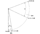
すなわち、図29に示すように、ロック機構120は、規制状態において、排藁切断装置28が作業位置から非作業位置側に一定角度範囲(第一許容角度θ1)だけ揺動するのを許容し、かつ、排藁切断装置28が非作業位置から作業位置側に一定角度範囲(第二許容角度θ2)だけ揺動するのを許容する。第二許容角度θ2は、第一許容角度θ1よりも大きい角度に設定されている。   That is, as shown in FIG. 29, the lock mechanism 120 allows the displacement cutting device 28 to swing from the working position toward the non-working position by a predetermined angular range (first allowable angle θ1) in the restricted state. Also, the displacement and cutting device 28 is allowed to swing from the non-working position toward the working position by a predetermined angular range (second allowable angle θ2). The second allowable angle θ2 is set to be larger than the first allowable angle θ1.

〔制御ブロック〕
図30に示すように、制御ブロックには、制御装置132と、シリンダ45と、モータM1と、モータM2と、警報部133と、シリンダ45を操作する昇降スイッチ134と、モータM1を操作する切り替えスイッチ135と、排藁切断装置28の揺動軸心Z1周りの揺動角度を検出する角度検出センサ119と、排藁フレーム55の揺動軸心Y2周りの揺動角度を検出する角度検出センサ136と、が含まれている。
[Control block]
As shown in FIG. 30, in the control block, the control device 132, the cylinder 45, the motor M1, the motor M2, the alarm unit 133, the elevation switch 134 for operating the cylinder 45, and the switching for operating the motor M1. A switch 135, an angle detection sensor 119 detecting a swing angle around the swing axis Z1 of the displacement cutting device 28, and an angle detection sensor detecting a swing angle around the swing axis Y2 of the discharge frame 55 136, and are included.

昇降スイッチ134は、シリンダ45の伸長動作によって扱胴フレーム44及び排藁フレーム55を上昇させる上昇指令と、シリンダ45の縮長動作によって扱胴フレーム44及び排藁フレーム55を下降させる下降指令とを発する。昇降スイッチ134は、上昇指令を発する上昇操作部と、下降指令を発する下降操作部と、を備えている。前記上昇操作部を押し操作している間だけ、扱胴フレーム44及び排藁フレーム55が上昇し、前記下降操作部を押し操作している間だけ、扱胴フレーム44及び排藁フレーム55が下降する。   The raising and lowering switch 134 is a raising command for raising the threshing drum frame 44 and the displacement frame 55 by the extension operation of the cylinder 45, and a lowering command for lowering the threshing drum frame 44 and the displacement frame 55 by the reduction operation of the cylinder 45. It emits. The raising and lowering switch 134 includes a rising operation unit that issues a rising command, and a lowering operation unit that issues a falling command. The threshing drum frame 44 and the displacement frame 55 are lifted only while the elevating operation portion is pushed, and the threshing cylinder frame 44 and the displacement frame 55 are lowered only while the elevating operation portion is pushed. Do.

切り替えスイッチ135は、モータM1によって切り替え板31を切断位置と非切断位置とに切り替える切り替え指令を発する。警報部133は、例えば、音声出力装置(スピーカ等)や表示装置(ディスプレイ、回転灯等)によって構成することができる。制御装置132は、昇降制御部137と、切り替え制御部138と、警報制御部139と、を備えている。   The switching switch 135 issues a switching command to switch the switching plate 31 between the cutting position and the non-cutting position by the motor M1. The alarm unit 133 can be configured by, for example, an audio output device (such as a speaker) or a display device (such as a display or a rotating light). The control device 132 includes an elevation control unit 137, a switching control unit 138, and an alarm control unit 139.

昇降制御部137は、昇降スイッチ134の指令に応じて、シリンダ45の昇降制御を行う。図31及び図33示すように、排藁切断装置28が作業位置に位置している状態において、昇降スイッチ134によって第一上昇位置まで上昇させる上昇指令が発せられると、昇降制御部137は、排藁フレーム55を第一上昇位置まで上昇させる。同様に、図31及び図34示すように、排藁切断装置28が非作業位置に位置している状態において、昇降スイッチ134によって第一上昇位置まで上昇させる上昇指令が発せられると、昇降制御部137は、排藁フレーム55を第一上昇位置まで上昇させる。   The elevation control unit 137 performs elevation control of the cylinder 45 in accordance with the command of the elevation switch 134. As shown in FIG. 31 and FIG. 33, when the lifting and lowering switch 134 issues a lifting command to raise to the first lifting position with the displacement and cutting device 28 positioned at the working position, the lifting and lowering control unit 137 The weir frame 55 is raised to the first elevation position. Similarly, as shown in FIGS. 31 and 34, when the lifting and lowering switch 134 issues an elevation command to raise to the first elevation position while the displacement and cutting device 28 is in the non-working position, the elevation control unit 137 lifts the displacement frame 55 to the first raised position.

しかし、図31及び図35示すように、排藁切断装置28が作業位置と非作業位置との中間に位置している状態(排藁切断装置28が作業位置でもなく、かつ、非作業位置でもない位置(以下、「中間位置」という。)に位置している状態)において、昇降スイッチ134によって第一上昇位置まで上昇させる上昇指令が発せられても、昇降制御部137は、排藁フレーム55を第一上昇位置まで上昇させない。すなわち、排藁切断装置28が中間位置に位置している状態では、昇降スイッチ134によって第一上昇位置まで上昇させる上昇指令が発せられても、排藁フレーム55を第二上昇位置までしか上昇させることができない。   However, as shown in FIG. 31 and FIG. 35, the state in which the drainage cutting device 28 is located in the middle between the working position and the non-working position (even in the non-working position and not the working position Even when the lift switch 134 issues a lift command to raise the first lift position to the first lift position when the lift switch 134 is not positioned (hereinafter referred to as “intermediate position”), the lift control unit 137 can Not raise to the first elevation position. That is, in a state in which the discharge and cutting device 28 is positioned at the intermediate position, the discharge frame 55 is raised only to the second raised position even if a lift command to raise the first lift position is issued by the lift switch 134. I can not do it.

ここで、昇降制御部137は、排藁フレーム55を第一上昇位置まで上昇させる際に、排藁フレーム55を第一上昇位置まで一気に上昇させずに、排藁フレーム55を第二上昇位置で一時停止する。そして、一時停止後、昇降スイッチ134によって第一上昇位置まで上昇させる上昇指令が発せられると、昇降制御部137は、排藁フレーム55を第二上昇位置から第一上昇位置まで上昇させる。一方、昇降制御部137は、排藁フレーム55を第一上昇位置から下降位置まで下降させる際は、第一上昇位置から下降位置まで一気に下降させる。   Here, when raising / lowering the displacement frame 55 to the first elevation position, the elevation control unit 137 does not raise the displacement frame 55 to the first elevation position at a stroke, and the displacement frame 55 is at the second elevation position. Pause. Then, after the temporary stop, when a lift command to raise to the first lift position is issued by the lift switch 134, the lift control unit 137 lifts the displacement frame 55 from the second lift position to the first lift position. On the other hand, when lowering the displacement frame 55 from the first raising position to the lowering position, the elevation control unit 137 makes a rapid lowering from the first raising position to the lowering position.

切り替え制御部138は、切り替えスイッチ135の指令に応じて、モータM1の切り替え制御を行う。図32及び図34に示すように、排藁切断装置28が非作業位置に位置している状態では、排藁フレーム55が第一上昇位置及び第二上昇位置の何れの位置まで上昇している場合でも、切り替えスイッチ135によって切り替え指令が発せられると、切り替え制御部138は、切り替え板31を切断位置と非切断位置とに切り替える。しかし、図32及び図33に示すように、排藁切断装置28が作業位置に位置している状態では、排藁フレーム55が第一上昇位置及び第二上昇位置の何れの位置まで上昇している場合でも、切り替えスイッチ135によって切り替え指令が発せられても、切り替え制御部138は、切り替え板31を切断位置と非切断位置とに切り替えない。   The switching control unit 138 performs switching control of the motor M <b> 1 in accordance with the command of the switching switch 135. As shown in FIG. 32 and FIG. 34, in the state where the drainage cutting device 28 is located at the non-working position, the drainage frame 55 is lifted to any position of the first lifting position and the second lifting position Even in this case, when the switching command is issued by the switching switch 135, the switching control unit 138 switches the switching plate 31 between the cutting position and the non-cutting position. However, as shown in FIGS. 32 and 33, in the state where the drainage cutting device 28 is located at the working position, the drainage frame 55 is raised to any position of the first raising position and the second raising position. Even in the case where the switching command is issued by the switching switch 135, the switching control unit 138 does not switch the switching plate 31 between the cutting position and the non-cutting position.

警報制御部139は、警報部133の警報制御を行う。排藁フレーム55が第二上昇位置で一時停止する際、一時停止したことを知らせるべく、警報制御部139は、警報部133によって警報を発する。排藁フレーム55が第一上昇位置まで上昇している状態において、排藁切断装置28を作業位置と非作業位置とに切り替えようとすると、警報制御部139は、警報部133によって警報を発する。   The alarm control unit 139 performs alarm control of the alarm unit 133. When the discharge frame 55 is temporarily stopped at the second raised position, the alarm control unit 139 issues an alarm by the alarm unit 133 to notify that the temporary stop has been performed. The alarm control unit 139 causes the alarm unit 133 to issue an alarm when the displacement / cutting device 28 is to be switched between the working position and the non-working position in a state where the displacement frame 55 is raised to the first raised position.

詳述すると、図29に示すように、排藁フレーム55が第一上昇位置まで上昇している状態では、排藁切断装置28を作業位置から非作業位置側に揺動させると、警報制御部139は、警報部133による警報を第一ロック位置に達する手前(作業位置と第一ロック位置との間)で行う。排藁フレーム55が第一上昇位置まで上昇している状態では、排藁切断装置28を非作業位置から作業位置側に揺動させると、警報制御部139は、警報部133による警報を第二ロック位置に達する手前(非作業位置と第二ロック位置との間)で行う。   More specifically, as shown in FIG. 29, in the state where the displacement frame 55 is raised to the first raised position, when the displacement / cutting device 28 is swung from the working position to the non-working position, the alarm control unit In 139, the alarm unit 133 performs an alarm before reaching the first lock position (between the work position and the first lock position). In the state where the displacement frame 55 is raised to the first raised position, when the displacement / cutting device 28 is swung from the non-working position toward the working position, the alarm control unit 139 generates the second alarm by the alarm unit 133. It takes place before reaching the lock position (between the non-working position and the second lock position).

〔角度検出センサ用のブラケット〕
図16に示すように、角度検出センサ119が取り付けられるブラケット140が設けられている。ブラケット140は、ステー141にボルト固定されている。ステー141は、上側の支持部115の下部に固定されている。すなわち、角度検出センサ119は、排藁切断装置28を揺動可能に支持する上側の支持部115に設けられている。ブラケット140には、検出アーム119aが初期位置から検出範囲外に揺動しないように検出アーム119aの揺動を阻止するストッパ140aが設けられている。検出アーム119aは、初期位置でストッパ140aに接触し、ストッパ140aによって初期位置から検出範囲外に揺動しないように揺動が阻止される。
[Bracket for angle detection sensor]
As shown in FIG. 16, a bracket 140 to which the angle detection sensor 119 is attached is provided. The bracket 140 is bolted to the stay 141. The stay 141 is fixed to the lower portion of the upper support portion 115. That is, the angle detection sensor 119 is provided on the upper support portion 115 that swingably supports the displacement cutting device 28. The bracket 140 is provided with a stopper 140a that prevents the detection arm 119a from swinging so that the detection arm 119a does not swing out of the detection range from the initial position. The detection arm 119a contacts the stopper 140a at the initial position, and the stopper 140a prevents the rocking from being rocked out of the detection range from the initial position.

ここで、上述のように、検出アーム119aは、フレーム116に接触しているが、仮に、ストッパ140aが設けられていない場合、排藁切断装置28が上下一対の支軸114から取り外された状態では、検出アーム119aが接触する対象が存在しないことになる。そうすると、検出アーム119aが初期位置から検出範囲外に揺動することになり、排藁フレーム55の昇降に支障を来たすという不都合が懸念される。例えば、検出アーム119aが初期位置から検出範囲外に揺動して、角度検出センサ119の検出値が排藁切断装置28が中間位置に位置している状態の検出値を示すことになると、排藁フレーム55を第一上昇位置まで上昇させることができない。   Here, as described above, the detection arm 119a is in contact with the frame 116. However, if the stopper 140a is not provided, the exhaust cutting device 28 is removed from the pair of upper and lower support shafts 114. In this case, there is no target with which the detection arm 119a contacts. Then, the detection arm 119a is swung from the initial position to the outside of the detection range, and there is a concern that the raising and lowering of the displacement frame 55 may be disturbed. For example, when the detection arm 119a swings from the initial position to the outside of the detection range and the detection value of the angle detection sensor 119 indicates the detection value of the state where the discharge / cutting device 28 is positioned at the middle position, The weir frame 55 can not be raised to the first elevation position.

しかし、上記構成によれば、排藁切断装置28を上下一対の支軸114から取り外したとしても、ストッパ140aが機体側に残ることになり、これにより、検出アーム119aの揺動がストッパ140aによって阻止されるため、上述のような不都合を回避することができる。   However, according to the above configuration, even if the exhaust cutting device 28 is removed from the pair of upper and lower support shafts 114, the stopper 140a remains on the machine body side, whereby the swing of the detection arm 119a is caused by the stopper 140a. Since it is blocked, the above-mentioned inconvenience can be avoided.

〔別実施形態〕
(1)上記実施形態では、排藁切断装置28用の「ロック機構」として、機械式のロック機構が採用されているが、例えば、排藁切断装置28がモータによって作業位置と非作業位置とに切り替えられるように構成されている場合、排藁切断装置28用の「ロック機構」として、制御装置132によるロック機構が採用されていてもよい。
[Another embodiment]
(1) In the above embodiment, a mechanical lock mechanism is employed as the “lock mechanism” for the drainage cutting device 28. For example, the drainage cutting device 28 uses a motor for working and non-working positions. When it is configured to be switched to, the lock mechanism by the control device 132 may be adopted as the “lock mechanism” for the drainage cutting device 28.

(2)上記実施形態では、排藁フレーム55の上昇限界として、第一上昇位置と、第一上昇位置よりも低い第二上昇位置と、が設定されているが、これに加えて、第二上昇位置よりも低い上昇位置や、第一上昇位置よりも低くかつ第二上昇位置よりも高い上昇位置が設定されていてもよい。 (2) In the above embodiment, the first lifting position and the second lifting position lower than the first lifting position are set as the lifting limit of the displacement frame 55, but in addition to this, the second lifting position A rising position lower than the rising position or a rising position lower than the first rising position and higher than the second rising position may be set.

(3)上記実施形態では、排藁フレーム55を第一上昇位置まで上昇させる際に、排藁フレーム55が第二上昇位置で一時停止するように構成されているが、排藁フレーム55が第一上昇位置まで一気に上昇するように構成されていてもよい。 (3) In the above embodiment, when the discharge frame 55 is raised to the first raised position, the discharge frame 55 is configured to be temporarily stopped at the second raised position. It may be configured to ascend at a stretch to the first elevation position.

(4)上記実施形態では、排藁フレーム55を第一上昇位置から下降位置まで下降させる際に、排藁フレーム55が第一上昇位置から下降位置まで一気に下降するように構成されているが、排藁フレーム55が第二上昇位置で一時停止するように構成されていてもよい。 (4) In the above embodiment, when the evacuation frame 55 is lowered from the first raising position to the lowering position, the evacuation frame 55 is configured to descend at a stretch from the first raising position to the lowering position. The displacement frame 55 may be configured to pause at the second raised position.

(5)上記実施形態では、ロック機構120は、規制状態において、排藁切断装置28が作業位置から非作業位置側に一定角度範囲(第一許容角度θ1)だけ揺動するのを許容し、かつ、排藁切断装置28が非作業位置から作業位置側に一定角度範囲(第二許容角度θ2)だけ揺動するのを許容する。しかし、ロック機構120は、規制状態において、排藁切断装置28が作業位置から非作業位置側に一定角度範囲だけ揺動するのを許容し、かつ、排藁切断装置28が非作業位置から作業位置側に一定角度範囲だけ揺動するのを許容しなくてもよい。あるいは、ロック機構120は、規制状態において、排藁切断装置28が作業位置から非作業位置側に一定角度範囲だけ揺動するのを許容せず、かつ、排藁切断装置28が非作業位置から作業位置側に一定角度範囲だけ揺動するのを許容してもよい。あるいは、ロック機構120は、規制状態において、排藁切断装置28が作業位置から非作業位置側に一定角度範囲だけ揺動するのを許容せず、かつ、排藁切断装置28が非作業位置から作業位置側に一定角度範囲だけ揺動するのを許容しなくてもよい。 (5) In the above embodiment, the lock mechanism 120 allows the displacement cutting device 28 to swing from the working position toward the non-working position by a predetermined angular range (first allowable angle θ1) in the restricted state, Also, the displacement and cutting device 28 is allowed to swing from the non-working position toward the working position by a predetermined angular range (second allowable angle θ2). However, in the restricted state, the lock mechanism 120 allows the displacement cutting device 28 to swing from the working position toward the non-working position by a certain angle range, and the displacement cutting device 28 works from the non-working position It is not necessary to allow the position side to swing by a certain angle range. Alternatively, the lock mechanism 120 does not allow the displacement cutting device 28 to swing from the working position to the non-working position side by a certain angle range in the restricted state, and the displacement cutting device 28 from the non-working position It may be permitted to swing to the working position side by a certain angle range. Alternatively, the lock mechanism 120 does not allow the displacement cutting device 28 to swing from the working position to the non-working position side by a certain angle range in the restricted state, and the displacement cutting device 28 from the non-working position It is not necessary to allow the working position to swing by a certain angular range.

本発明は、コンバイン(例えば、自脱型コンバイン)に利用可能である。   The present invention is applicable to combine harvesters (for example, self-contained combine harvesters).

9 フィードチェーン
10 脱穀装置
11 扱胴
12 排藁搬送装置
28 排藁切断装置
55 排藁フレーム
115 支持部
119 角度検出センサ
119a 検出アーム
120 ロック機構
127 連動機構
133 警報部
140 ブラケット
140a ストッパ
Y2 揺動軸心
Z1 揺動軸心
θ1 第一許容角度
θ2 第二許容角度
9 feed chain 10 threshing device 11 threshing drum 12 displacement conveying device 28 displacement cutting device 55 displacement frame 115 support portion 119 angle detection sensor 119a detection arm 120 lock mechanism 127 interlocking mechanism 133 alarm portion 140 bracket 140a stopper Y2 pivot shaft Center Z1 Swing axis center θ1 First allowable angle θ2 Second allowable angle

Claims (7)

刈取穀稈を挟持搬送するフィードチェーンと、
扱胴を有すると共に前記フィードチェーンによって搬送される刈取穀稈を脱穀処理する脱穀装置と、
前記脱穀装置の後側に連設されると共に前記フィードチェーンから脱穀処理後の排藁を受け取って後方へ挟持搬送する排藁搬送装置と、
前記排藁搬送装置の搬送終端側部位の下方に設けられると共に前記排藁搬送装置によって搬送された排藁を切断処理する排藁切断装置と、が備えられたコンバインであって、
前記排藁切断装置は、左右一端部側で上下方向に延びる揺動軸心周りにおいて、前記排藁搬送装置の搬送終端側部位の下方に位置する作業位置と、前記排藁搬送装置の搬送終端側部位の下方から離れて位置する非作業位置とに亘って揺動可能であり、
前記排藁搬送装置を平面視で前記排藁搬送装置の搬送終端側ほど機体左右方向の一方側に位置するように傾斜する状態で支持すると共に機体左右方向の前記一方側で機体前後方向に延びる揺動軸心周りで上下揺動可能な排藁フレームが備えられ、
前記排藁フレームの上昇限界として、少なくとも、第一上昇位置と、前記第一上昇位置よりも低い第二上昇位置と、が設定され、
前記排藁フレームが前記第二上昇位置まで上昇している状態では、前記排藁切断装置を前記作業位置と前記非作業位置とに切り替え可能であり、
前記排藁フレームが前記第一上昇位置まで上昇している状態では、前記排藁切断装置を前記作業位置と前記非作業位置とに切り替え不可能であるコンバイン。
A feed chain for holding and transporting a reaper
A threshing device having a threshing cylinder and threshing a reaping cropping grain carried by the feed chain;
A waste transport device which is connected to the rear side of the threshing device and receives the waste after threshing treatment from the feed chain and nips and transports it backward;
And a drainage / cutting device provided under the conveyance end side portion of the drainage / conveying device and cutting the drainage conveyed by the drainage / conveying device,
The displacement cutting device has a work position located below the transport end side portion of the displacement and transport device around a swing axis extending vertically in the left and right end portions, and the transport end of the displacement and transport device Swingable over a non-working position located away from below the side part,
The exhaust transport device is supported in an inclined state so as to be positioned on one side in the left-right direction of the machine toward the transport end side of the discharge transport device in plan view and extends in the front-rear direction on the one side in the left-right direction A displacement frame is provided which can be pivoted up and down around the pivot axis,
As a rising limit of the displacement frame, at least a first rising position and a second rising position lower than the first rising position are set.
In the state where the displacement frame is raised to the second raised position, the displacement / cutting device can be switched between the working position and the non-working position,
The combine which can not switch the displacement-cutting device between the working position and the non-working position when the displacement frame is raised to the first raised position.
前記排藁切断装置の前記作業位置から前記非作業位置側への揺動と、前記排藁切断装置の前記非作業位置から前記作業位置側への揺動とを規制するロック機構が備えられている請求項1に記載のコンバイン。   A lock mechanism is provided which restricts the swinging of the displacement cutting device from the working position to the non-working position and the swinging of the displacement cutting device from the non-working position to the working position. The combine according to claim 1. 前記排藁フレームの上昇に連動して前記ロック機構が前記排藁切断装置の揺動を規制するように、前記排藁フレームの上昇動作に前記ロック機構の規制動作を連動させる連動機構が備えられている請求項2に記載のコンバイン。   An interlocking mechanism is provided which interlocks the restraining operation of the lock mechanism with the elevating operation of the eliminator frame so that the lock mechanism restraining the swing of the eliminator cutting device interlockingly with the elevating of the eliminator frame The combine according to claim 2. 前記ロック機構は、前記排藁切断装置の揺動を規制する状態において、前記排藁切断装置が一定角度範囲だけ揺動するのを許容する請求項2又は3に記載のコンバイン。   The combine according to claim 2 or 3, wherein the lock mechanism allows the displacement and cutting device to swing by a predetermined angular range in a state in which the displacement of the displacement and cutting device is regulated. 前記排藁切断装置の揺動角度を検出する角度検出センサが備えられ、
前記角度検出センサは、前記排藁切断装置を揺動可能に支持する支持部に設けられている請求項1から4の何れか一項に記載のコンバイン。
An angle detection sensor for detecting a swing angle of the displacement cutting device is provided.
The combine according to any one of claims 1 to 4 in which said angle detection sensor is provided in a support part which supports said displacement cutting device so that rocking movement is possible.
前記角度検出センサが取り付けられるブラケットが備えられ、
前記角度検出センサは、揺動式の検出アームを有し、
前記ブラケットに、前記検出アームが初期位置から検出範囲外に揺動しないように前記検出アームの揺動を阻止するストッパが設けられている請求項5に記載のコンバイン。
A bracket on which the angle detection sensor is mounted;
The angle detection sensor has a rocking detection arm,
The combine according to claim 5, wherein the bracket is provided with a stopper that prevents the detection arm from swinging so that the detection arm does not swing out of the detection range from the initial position.
前記排藁フレームが前記第一上昇位置まで上昇している状態において、前記排藁切断装置を前記作業位置と前記非作業位置とに切り替えようとすると警報を発する警報部が備えられている請求項1から6の何れか一項に記載のコンバイン。
In the state where the displacement frame is raised to the first raised position, an alarm unit is provided which issues an alarm when the displacement / cutting device is to be switched to the working position and the non-working position. The combine according to any one of 1 to 6.
JP2017242092A 2017-12-18 2017-12-18 combine Active JP6947622B2 (en)

Priority Applications (4)

Application Number Priority Date Filing Date Title
JP2017242092A JP6947622B2 (en) 2017-12-18 2017-12-18 combine
KR1020180156603A KR102687536B1 (en) 2017-12-18 2018-12-07 Combine and rice straw cutting apparatus
CN201811552772.0A CN109923997B (en) 2017-12-18 2018-12-18 Combine harvester and straw discharging and cutting device
JP2021151263A JP7262543B2 (en) 2017-12-18 2021-09-16 combine

Applications Claiming Priority (1)

Application Number Priority Date Filing Date Title
JP2017242092A JP6947622B2 (en) 2017-12-18 2017-12-18 combine

Related Child Applications (1)

Application Number Title Priority Date Filing Date
JP2021151263A Division JP7262543B2 (en) 2017-12-18 2021-09-16 combine

Publications (2)

Publication Number Publication Date
JP2019106931A true JP2019106931A (en) 2019-07-04
JP6947622B2 JP6947622B2 (en) 2021-10-13

Family

ID=67178024

Family Applications (2)

Application Number Title Priority Date Filing Date
JP2017242092A Active JP6947622B2 (en) 2017-12-18 2017-12-18 combine
JP2021151263A Active JP7262543B2 (en) 2017-12-18 2021-09-16 combine

Family Applications After (1)

Application Number Title Priority Date Filing Date
JP2021151263A Active JP7262543B2 (en) 2017-12-18 2021-09-16 combine

Country Status (1)

Country Link
JP (2) JP6947622B2 (en)

Cited By (2)

* Cited by examiner, † Cited by third party
Publication number Priority date Publication date Assignee Title
JP2020048424A (en) * 2018-09-21 2020-04-02 株式会社クボタ Combine
CN114679967A (en) * 2022-03-24 2022-07-01 安徽禾吉循环经济园有限公司 Crop straw cutting and washing machine

Citations (8)

* Cited by examiner, † Cited by third party
Publication number Priority date Publication date Assignee Title
US4669489A (en) * 1985-12-02 1987-06-02 Deere & Company Straw chopper mounting for a combine
JPS6485011A (en) * 1987-09-24 1989-03-30 Iseki Agricult Mach Waste stalk cutter
JPH08228575A (en) * 1995-02-28 1996-09-10 Mitsubishi Agricult Mach Co Ltd Apparatus for treating waste straw in combine harvester
JPH104768A (en) * 1996-06-17 1998-01-13 Mitsubishi Agricult Mach Co Ltd Straw discharging apparatus for thresher
JP2001204241A (en) * 2000-01-25 2001-07-31 Mitsubishi Agricult Mach Co Ltd Thresher
JP2003304729A (en) * 2002-04-17 2003-10-28 Atex Co Ltd Waste culm guiding apparatus of waste culm cutter
JP2008301773A (en) * 2007-06-08 2008-12-18 Kubota Corp Waste straw treatment structure
JP2009232819A (en) * 2008-03-28 2009-10-15 Mitsubishi Agricult Mach Co Ltd Combine

Family Cites Families (3)

* Cited by examiner, † Cited by third party
Publication number Priority date Publication date Assignee Title
JP3044932B2 (en) * 1992-07-23 2000-05-22 井関農機株式会社 Threshing machine
JPH099777A (en) * 1995-06-28 1997-01-14 Mitsubishi Agricult Mach Co Ltd Discharged straw-carrying device in thresher
JP3410616B2 (en) * 1996-10-03 2003-05-26 三菱農機株式会社 Combine

Patent Citations (8)

* Cited by examiner, † Cited by third party
Publication number Priority date Publication date Assignee Title
US4669489A (en) * 1985-12-02 1987-06-02 Deere & Company Straw chopper mounting for a combine
JPS6485011A (en) * 1987-09-24 1989-03-30 Iseki Agricult Mach Waste stalk cutter
JPH08228575A (en) * 1995-02-28 1996-09-10 Mitsubishi Agricult Mach Co Ltd Apparatus for treating waste straw in combine harvester
JPH104768A (en) * 1996-06-17 1998-01-13 Mitsubishi Agricult Mach Co Ltd Straw discharging apparatus for thresher
JP2001204241A (en) * 2000-01-25 2001-07-31 Mitsubishi Agricult Mach Co Ltd Thresher
JP2003304729A (en) * 2002-04-17 2003-10-28 Atex Co Ltd Waste culm guiding apparatus of waste culm cutter
JP2008301773A (en) * 2007-06-08 2008-12-18 Kubota Corp Waste straw treatment structure
JP2009232819A (en) * 2008-03-28 2009-10-15 Mitsubishi Agricult Mach Co Ltd Combine

Cited By (3)

* Cited by examiner, † Cited by third party
Publication number Priority date Publication date Assignee Title
JP2020048424A (en) * 2018-09-21 2020-04-02 株式会社クボタ Combine
CN114679967A (en) * 2022-03-24 2022-07-01 安徽禾吉循环经济园有限公司 Crop straw cutting and washing machine
CN114679967B (en) * 2022-03-24 2024-01-26 安徽禾吉循环经济园有限公司 Crop straw cutting and washing machine

Also Published As

Publication number Publication date
JP2021184776A (en) 2021-12-09
JP6947622B2 (en) 2021-10-13
JP7262543B2 (en) 2023-04-21

Similar Documents

Publication Publication Date Title
JP5384840B2 (en) Combine
JP7262543B2 (en) combine
JP2021184776A5 (en)
JP2019106930A (en) Combine
JP5374125B2 (en) Combine
CN109923997B (en) Combine harvester and straw discharging and cutting device
JP2019097558A (en) Combine
JP2014079222A (en) Grain discharge structure of combine harvester
JP6693862B2 (en) Combine
JP7206181B2 (en) combine
JP2015231356A (en) General-purpose combine-harvester
JP6040923B2 (en) Combine
JP6721541B2 (en) combine
CN108781721B (en) combine harvester
JP6983130B2 (en) combine
JP5632739B2 (en) Combine grain discharge structure
JP2009165420A (en) Threshing device
JP7155380B2 (en) combine
JP2013183677A (en) Combine harvester
KR20200034567A (en) Combine
JP6721540B2 (en) combine
JPWO2007148719A1 (en) Combine
JP6980629B2 (en) combine
JP2008182998A (en) Combine harvester
JP6615084B2 (en) Combine

Legal Events

Date Code Title Description
A621 Written request for application examination

Free format text: JAPANESE INTERMEDIATE CODE: A621

Effective date: 20191225

A977 Report on retrieval

Free format text: JAPANESE INTERMEDIATE CODE: A971007

Effective date: 20201225

A131 Notification of reasons for refusal

Free format text: JAPANESE INTERMEDIATE CODE: A131

Effective date: 20210202

A521 Request for written amendment filed

Free format text: JAPANESE INTERMEDIATE CODE: A523

Effective date: 20210402

TRDD Decision of grant or rejection written
A01 Written decision to grant a patent or to grant a registration (utility model)

Free format text: JAPANESE INTERMEDIATE CODE: A01

Effective date: 20210817

A61 First payment of annual fees (during grant procedure)

Free format text: JAPANESE INTERMEDIATE CODE: A61

Effective date: 20210916

R150 Certificate of patent or registration of utility model

Ref document number: 6947622

Country of ref document: JP

Free format text: JAPANESE INTERMEDIATE CODE: R150