JP2019109089A - 電磁流量計の電位検出用電極 - Google Patents
電磁流量計の電位検出用電極 Download PDFInfo
- Publication number
- JP2019109089A JP2019109089A JP2017240991A JP2017240991A JP2019109089A JP 2019109089 A JP2019109089 A JP 2019109089A JP 2017240991 A JP2017240991 A JP 2017240991A JP 2017240991 A JP2017240991 A JP 2017240991A JP 2019109089 A JP2019109089 A JP 2019109089A
- Authority
- JP
- Japan
- Prior art keywords
- diameter portion
- electrode
- conductor
- large diameter
- annular groove
- Prior art date
- Legal status (The legal status is an assumption and is not a legal conclusion. Google has not performed a legal analysis and makes no representation as to the accuracy of the status listed.)
- Granted
Links
Images




Classifications
-
- G—PHYSICS
- G01—MEASURING; TESTING
- G01F—MEASURING VOLUME, VOLUME FLOW, MASS FLOW OR LIQUID LEVEL; METERING BY VOLUME
- G01F1/00—Measuring the volume flow or mass flow of fluid or fluent solid material wherein the fluid passes through a meter in a continuous flow
- G01F1/56—Measuring the volume flow or mass flow of fluid or fluent solid material wherein the fluid passes through a meter in a continuous flow by using electric or magnetic effects
- G01F1/58—Measuring the volume flow or mass flow of fluid or fluent solid material wherein the fluid passes through a meter in a continuous flow by using electric or magnetic effects by electromagnetic flowmeters
- G01F1/584—Measuring the volume flow or mass flow of fluid or fluent solid material wherein the fluid passes through a meter in a continuous flow by using electric or magnetic effects by electromagnetic flowmeters constructions of electrodes, accessories therefor
-
- G—PHYSICS
- G01—MEASURING; TESTING
- G01F—MEASURING VOLUME, VOLUME FLOW, MASS FLOW OR LIQUID LEVEL; METERING BY VOLUME
- G01F1/00—Measuring the volume flow or mass flow of fluid or fluent solid material wherein the fluid passes through a meter in a continuous flow
- G01F1/56—Measuring the volume flow or mass flow of fluid or fluent solid material wherein the fluid passes through a meter in a continuous flow by using electric or magnetic effects
- G01F1/58—Measuring the volume flow or mass flow of fluid or fluent solid material wherein the fluid passes through a meter in a continuous flow by using electric or magnetic effects by electromagnetic flowmeters
- G01F1/588—Measuring the volume flow or mass flow of fluid or fluent solid material wherein the fluid passes through a meter in a continuous flow by using electric or magnetic effects by electromagnetic flowmeters combined constructions of electrodes, coils or magnetic circuits, accessories therefor
-
- G—PHYSICS
- G01—MEASURING; TESTING
- G01F—MEASURING VOLUME, VOLUME FLOW, MASS FLOW OR LIQUID LEVEL; METERING BY VOLUME
- G01F23/00—Indicating or measuring liquid level or level of fluent solid material, e.g. indicating in terms of volume or indicating by means of an alarm
- G01F23/22—Indicating or measuring liquid level or level of fluent solid material, e.g. indicating in terms of volume or indicating by means of an alarm by measuring physical variables, other than linear dimensions, pressure or weight, dependent on the level to be measured, e.g. by difference of heat transfer of steam or water
- G01F23/24—Indicating or measuring liquid level or level of fluent solid material, e.g. indicating in terms of volume or indicating by means of an alarm by measuring physical variables, other than linear dimensions, pressure or weight, dependent on the level to be measured, e.g. by difference of heat transfer of steam or water by measuring variations of resistance of resistors due to contact with conductor fluid
-
- G—PHYSICS
- G01—MEASURING; TESTING
- G01N—INVESTIGATING OR ANALYSING MATERIALS BY DETERMINING THEIR CHEMICAL OR PHYSICAL PROPERTIES
- G01N27/00—Investigating or analysing materials by the use of electric, electrochemical, or magnetic means
- G01N27/02—Investigating or analysing materials by the use of electric, electrochemical, or magnetic means by investigating impedance
- G01N27/04—Investigating or analysing materials by the use of electric, electrochemical, or magnetic means by investigating impedance by investigating resistance
- G01N27/06—Investigating or analysing materials by the use of electric, electrochemical, or magnetic means by investigating impedance by investigating resistance of a liquid
-
- G—PHYSICS
- G01—MEASURING; TESTING
- G01N—INVESTIGATING OR ANALYSING MATERIALS BY DETERMINING THEIR CHEMICAL OR PHYSICAL PROPERTIES
- G01N27/00—Investigating or analysing materials by the use of electric, electrochemical, or magnetic means
- G01N27/02—Investigating or analysing materials by the use of electric, electrochemical, or magnetic means by investigating impedance
- G01N27/04—Investigating or analysing materials by the use of electric, electrochemical, or magnetic means by investigating impedance by investigating resistance
- G01N27/06—Investigating or analysing materials by the use of electric, electrochemical, or magnetic means by investigating impedance by investigating resistance of a liquid
- G01N27/07—Construction of measuring vessels; Electrodes therefor
Landscapes
- Physics & Mathematics (AREA)
- General Physics & Mathematics (AREA)
- Fluid Mechanics (AREA)
- Electromagnetism (AREA)
- Chemical & Material Sciences (AREA)
- Health & Medical Sciences (AREA)
- Analytical Chemistry (AREA)
- Biochemistry (AREA)
- General Health & Medical Sciences (AREA)
- Life Sciences & Earth Sciences (AREA)
- Immunology (AREA)
- Pathology (AREA)
- Electrochemistry (AREA)
- Chemical Kinetics & Catalysis (AREA)
- Thermal Sciences (AREA)
- Measuring Volume Flow (AREA)
- Investigating Or Analyzing Materials By The Use Of Electric Means (AREA)
Abstract
Description
この貴金属材料が剥がれると、下地金属と貴金属材料との電位差により電気化学的なノイズが発生する。このノイズは、電磁流量計の出力ノイズとなる。
本発明は、前記電磁流量計の電位検出用電極において、前記環状溝は、ガスケットを収容する溝であってもよい。
したがって、本発明によれば、環状溝と、導電体で覆われた本体部とを有しているにもかかわらず、導通の信頼性が高くなる電位検出用電極を提供することができる。
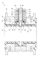
以下、本発明に係る電磁流量計の電位検出用電極の一実施の形態を図1〜図5を参照して詳細に説明する。
図1に示す電位検出用電極11(以下、単に電極11という。)は、電磁流量計12の測定管13に流体通路14の外側から取付けられている。
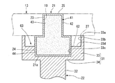
本体部21は、詳細は後述するが、図1〜図4に示すように、一端が測定管13内の流体通路14に臨む円柱状の小径部23と、この小径部23の他端から径方向の外側に延びる円板状の大径部24とによって形成されている。
母材41のセラミックス原料としては、SiC、Al2O3、ZrO2、Y2O3、Si3N4、SiOなどを使用することができる。母材41は、セラミックス原料を型(図示せず)によって本体部21の形状に成形し、この成形物を焼成することによって形成されている。
円板部44の外周部であって円板部44の一端側(円柱部43側)は、他端側より小径に形成されている。このため、円板部44の外周部には、図4に示すように、円板部44の軸線方向の一端面44aから軸線方向に延びる第1の周面44bと、この第1の周面44bから径方向の外側に延びて円板部44の最も外側の第2の周面44cに接続される端面44dとによって段部45が形成されている。
したがって、この実施の形態によれば、環状溝52と、導電体42で覆われた本体部21とを有しているにもかかわらず、導通の信頼性が高くなる電位検出用電極を提供することができる。
本発明に係る電磁流量計の電位検出用電極は図6および図7に示すように構成することができる。図6および図7において、図1〜図5によって説明したものと同一もしくは同等の部材については、同一符号を付し詳細な説明を適宜省略する。
図6および図7に示す電位検出用電極61は、外周部に段部が設けられていない円板状の大径部24を有する本体部21と、この本体部21の外周面が嵌合する筒体33を備えた端子部22とによって構成されている。本体部21の大径部24は、軸線方向の全域にわたって外径が一定となるように形成されている。
この実施の形態による電位検出用電極61においては、本体部21に端子部22が取付けられることによって、筒体33の内周部に設けられている環状の凹部62と、本体部21の大径部24との間に、測定管13内に向けて開放される環状溝63が形成される。この環状溝63は、ガスケット27を収容する溝である。
また、この実施の形態においては、第1の実施の形態を採る場合と較べて本体部21の大径部24に形成される角部が一つ減るため、導通の信頼性が高くなるという利点もある。
Claims (2)
- 電磁流量計の測定管の中に露出する接液部を有し、導電性を有する材料によって母材が覆われて形成された本体部と、
前記導電性を有する材料に電気的に接続された端子部とを備え、
前記本体部は、
前記測定管の電極挿入穴に挿入されて一端が前記接液部になる円柱状の小径部と、
前記小径部の他端に一端が接続されて前記小径部から径方向の外側に延びる円板状の大径部とを有し、
前記端子部は、
前記大径部が嵌合する筒体を有し、前記大径部に電気的に接続された有底円筒状の導通部と、
前記導通部から前記本体部とは反対方向に延びる軸部とを有し、
前記大径部の外周部と、前記筒体の内周部とのうちいずれか一方には、前記大径部と前記筒体との間に環状溝を構成する環状の凹部が形成されていることを特徴とする電磁流量計の電位検出用電極。 - 請求項1記載の電磁流量計の電位検出用電極において、
前記環状溝は、ガスケットを収容する溝であることを特徴とする電磁流量計の電位検出用電極。
Priority Applications (4)
| Application Number | Priority Date | Filing Date | Title |
|---|---|---|---|
| JP2017240991A JP6940392B2 (ja) | 2017-12-15 | 2017-12-15 | 電磁流量計の電位検出用電極 |
| US16/219,279 US10663330B2 (en) | 2017-12-15 | 2018-12-13 | Electropotential detection electrode of electromagnetic flow meter |
| KR1020180160782A KR102128855B1 (ko) | 2017-12-15 | 2018-12-13 | 전자 유량계의 전위 검출용 전극 |
| CN201811527276.XA CN109931993B (zh) | 2017-12-15 | 2018-12-13 | 电磁流量计的电位检测用电极 |
Applications Claiming Priority (1)
| Application Number | Priority Date | Filing Date | Title |
|---|---|---|---|
| JP2017240991A JP6940392B2 (ja) | 2017-12-15 | 2017-12-15 | 電磁流量計の電位検出用電極 |
Publications (2)
| Publication Number | Publication Date |
|---|---|
| JP2019109089A true JP2019109089A (ja) | 2019-07-04 |
| JP6940392B2 JP6940392B2 (ja) | 2021-09-29 |
Family
ID=66815869
Family Applications (1)
| Application Number | Title | Priority Date | Filing Date |
|---|---|---|---|
| JP2017240991A Active JP6940392B2 (ja) | 2017-12-15 | 2017-12-15 | 電磁流量計の電位検出用電極 |
Country Status (4)
| Country | Link |
|---|---|
| US (1) | US10663330B2 (ja) |
| JP (1) | JP6940392B2 (ja) |
| KR (1) | KR102128855B1 (ja) |
| CN (1) | CN109931993B (ja) |
Cited By (1)
| Publication number | Priority date | Publication date | Assignee | Title |
|---|---|---|---|---|
| WO2020250923A1 (ja) | 2019-06-11 | 2020-12-17 | 味の素株式会社 | ペプチド及びその用途 |
Families Citing this family (5)
| Publication number | Priority date | Publication date | Assignee | Title |
|---|---|---|---|---|
| JP6948244B2 (ja) * | 2017-12-15 | 2021-10-13 | アズビル株式会社 | 電磁流量計の電位検出用電極 |
| JP6970001B2 (ja) * | 2017-12-15 | 2021-11-24 | アズビル株式会社 | 電磁流量計の電位検出用電極 |
| RU206995U1 (ru) * | 2019-12-17 | 2021-10-06 | Общество с ограниченной ответственностью "Научно-производственное предприятие "Электротех" | Устройство для крепления электродного узла электромагнитного расходомера |
| RU202945U1 (ru) * | 2020-07-21 | 2021-03-16 | Алексей Анатольевич Воронцов | Устройство для крепления электродного узла электромагнитного расходомера |
| RU209745U1 (ru) * | 2021-10-04 | 2022-03-22 | Алексей Анатольевич Воронцов | Устройство для крепления электродного узла электромагнитного расходомера |
Family Cites Families (13)
| Publication number | Priority date | Publication date | Assignee | Title |
|---|---|---|---|---|
| JPS6023936Y2 (ja) * | 1980-03-12 | 1985-07-17 | 東光株式会社 | コイルを具えたリ−ドフレ−ム |
| US4782709A (en) * | 1985-08-19 | 1988-11-08 | Yamatake-Honeywell Co., Ltd. | Electromagnetic flowmeter |
| JPH0623936Y2 (ja) | 1988-04-27 | 1994-06-22 | 横河電機株式会社 | 電磁流量計の電極部構造 |
| JPH0216024A (ja) | 1988-05-04 | 1990-01-19 | Uk Atomic Energy Authority | 熱可塑性重合体からなる材料の押出成形方法及び装置 |
| JPH0216024U (ja) | 1988-07-19 | 1990-02-01 | ||
| JPH08271302A (ja) | 1995-03-31 | 1996-10-18 | Yamatake Honeywell Co Ltd | 電磁流量計 |
| CN2580408Y (zh) * | 2002-12-01 | 2003-10-15 | 中国石化集团江汉石油管理局仪表厂 | 井下电磁流量计传感器 |
| DE102006054635A1 (de) * | 2006-11-17 | 2008-05-21 | Endress + Hauser Flowtec Ag | Vorrichtung zum Messen des Volumen- oder Massestroms eines Mediums in einer Rohrleitung |
| DE102008036962A1 (de) * | 2008-08-08 | 2010-02-11 | Endress + Hauser Flowtec Ag | Magnetisch-induktives Durchflussmessgerät mit einer Elektrodenanordnung und Verfahren zu dessen Fertigung |
| DE102010030229A1 (de) * | 2010-06-17 | 2011-12-22 | Endress + Hauser Flowtec Ag | Verfahren zur Herstellung eines magnetisch-induktiven Durchflussmessgeräts |
| KR102396377B1 (ko) | 2015-09-30 | 2022-05-11 | 엘지디스플레이 주식회사 | 유기발광 표시장치 |
| JP6754312B2 (ja) | 2017-03-02 | 2020-09-09 | アズビル株式会社 | 電磁流量計の電極構造 |
| JP6970001B2 (ja) * | 2017-12-15 | 2021-11-24 | アズビル株式会社 | 電磁流量計の電位検出用電極 |
-
2017
- 2017-12-15 JP JP2017240991A patent/JP6940392B2/ja active Active
-
2018
- 2018-12-13 CN CN201811527276.XA patent/CN109931993B/zh not_active Expired - Fee Related
- 2018-12-13 KR KR1020180160782A patent/KR102128855B1/ko active Active
- 2018-12-13 US US16/219,279 patent/US10663330B2/en active Active
Cited By (1)
| Publication number | Priority date | Publication date | Assignee | Title |
|---|---|---|---|---|
| WO2020250923A1 (ja) | 2019-06-11 | 2020-12-17 | 味の素株式会社 | ペプチド及びその用途 |
Also Published As
| Publication number | Publication date |
|---|---|
| KR20190072454A (ko) | 2019-06-25 |
| CN109931993B (zh) | 2021-02-26 |
| KR102128855B1 (ko) | 2020-07-02 |
| US10663330B2 (en) | 2020-05-26 |
| JP6940392B2 (ja) | 2021-09-29 |
| CN109931993A (zh) | 2019-06-25 |
| US20190186966A1 (en) | 2019-06-20 |
Similar Documents
| Publication | Publication Date | Title |
|---|---|---|
| JP6940392B2 (ja) | 電磁流量計の電位検出用電極 | |
| JP3520309B2 (ja) | ガスセンサのセンサ素子のためのシール装置 | |
| JP6754312B2 (ja) | 電磁流量計の電極構造 | |
| CN106546376A (zh) | 压力传感器 | |
| JP2019109085A (ja) | 電磁流量計の電位検出用電極 | |
| JP6970001B2 (ja) | 電磁流量計の電位検出用電極 | |
| JP2019109086A (ja) | 電磁流量計の電位検出用電極 | |
| JP2005322749A (ja) | 接続端子の封止構造 | |
| JP5095915B2 (ja) | 酸素センサ | |
| JPH08254450A (ja) | 電磁流量計 | |
| JP2595285B2 (ja) | 懸濁粒子検出器 | |
| JP2687585B2 (ja) | 酸素濃度検出装置 | |
| JP2006200926A (ja) | 圧力センサ | |
| JPH0514176Y2 (ja) | ||
| JP6899342B2 (ja) | ガスセンサ | |
| JPS60239628A (ja) | 水位検出素子 | |
| JPS6210650Y2 (ja) | ||
| JPS62137520A (ja) | 電磁流量計電極部の製造方法 | |
| JP2002082086A (ja) | ガスセンサ | |
| JPH04106729U (ja) | 電磁流量計 | |
| JP2006145292A (ja) | 酸素センサ |
Legal Events
| Date | Code | Title | Description |
|---|---|---|---|
| A521 | Request for written amendment filed |
Free format text: JAPANESE INTERMEDIATE CODE: A523 Effective date: 20181217 |
|
| A621 | Written request for application examination |
Free format text: JAPANESE INTERMEDIATE CODE: A621 Effective date: 20200911 |
|
| TRDD | Decision of grant or rejection written | ||
| A977 | Report on retrieval |
Free format text: JAPANESE INTERMEDIATE CODE: A971007 Effective date: 20210728 |
|
| A01 | Written decision to grant a patent or to grant a registration (utility model) |
Free format text: JAPANESE INTERMEDIATE CODE: A01 Effective date: 20210810 |
|
| A61 | First payment of annual fees (during grant procedure) |
Free format text: JAPANESE INTERMEDIATE CODE: A61 Effective date: 20210902 |
|
| R150 | Certificate of patent or registration of utility model |
Ref document number: 6940392 Country of ref document: JP Free format text: JAPANESE INTERMEDIATE CODE: R150 |
|
| R250 | Receipt of annual fees |
Free format text: JAPANESE INTERMEDIATE CODE: R250 |
|
| R250 | Receipt of annual fees |
Free format text: JAPANESE INTERMEDIATE CODE: R250 |