JP2019115251A - 無停電電源供給装置 - Google Patents
無停電電源供給装置 Download PDFInfo
- Publication number
- JP2019115251A JP2019115251A JP2018177458A JP2018177458A JP2019115251A JP 2019115251 A JP2019115251 A JP 2019115251A JP 2018177458 A JP2018177458 A JP 2018177458A JP 2018177458 A JP2018177458 A JP 2018177458A JP 2019115251 A JP2019115251 A JP 2019115251A
- Authority
- JP
- Japan
- Prior art keywords
- power supply
- inductance
- arm
- switch
- cbus
- Prior art date
- Legal status (The legal status is an assumption and is not a legal conclusion. Google has not performed a legal analysis and makes no representation as to the accuracy of the status listed.)
- Granted
Links
Images









Classifications
-
- H—ELECTRICITY
- H02—GENERATION; CONVERSION OR DISTRIBUTION OF ELECTRIC POWER
- H02J—ELECTRIC POWER NETWORKS; CIRCUIT ARRANGEMENTS OR SYSTEMS FOR SUPPLYING OR DISTRIBUTING ELECTRIC POWER; SYSTEMS FOR STORING ELECTRIC ENERGY
- H02J9/00—Circuit arrangements for emergency or stand-by power supply, e.g. for emergency lighting
- H02J9/04—Circuit arrangements for emergency or stand-by power supply, e.g. for emergency lighting in which the distribution system is disconnected from the normal source and connected to a standby source
- H02J9/06—Circuit arrangements for emergency or stand-by power supply, e.g. for emergency lighting in which the distribution system is disconnected from the normal source and connected to a standby source with automatic change-over, e.g. UPS systems
- H02J9/062—Circuit arrangements for emergency or stand-by power supply, e.g. for emergency lighting in which the distribution system is disconnected from the normal source and connected to a standby source with automatic change-over, e.g. UPS systems for AC powered loads
-
- G—PHYSICS
- G06—COMPUTING OR CALCULATING; COUNTING
- G06F—ELECTRIC DIGITAL DATA PROCESSING
- G06F1/00—Details not covered by groups G06F3/00 - G06F13/00 and G06F21/00
- G06F1/26—Power supply means, e.g. regulation thereof
- G06F1/30—Means for acting in the event of power-supply failure or interruption, e.g. power-supply fluctuations
-
- H—ELECTRICITY
- H02—GENERATION; CONVERSION OR DISTRIBUTION OF ELECTRIC POWER
- H02M—APPARATUS FOR CONVERSION BETWEEN AC AND AC, BETWEEN AC AND DC, OR BETWEEN DC AND DC, AND FOR USE WITH MAINS OR SIMILAR POWER SUPPLY SYSTEMS; CONVERSION OF DC OR AC INPUT POWER INTO SURGE OUTPUT POWER; CONTROL OR REGULATION THEREOF
- H02M1/00—Details of apparatus for conversion
- H02M1/10—Arrangements incorporating converting means for enabling loads to be operated at will from different kinds of power supplies, e.g. from AC or DC
-
- H—ELECTRICITY
- H02—GENERATION; CONVERSION OR DISTRIBUTION OF ELECTRIC POWER
- H02M—APPARATUS FOR CONVERSION BETWEEN AC AND AC, BETWEEN AC AND DC, OR BETWEEN DC AND DC, AND FOR USE WITH MAINS OR SIMILAR POWER SUPPLY SYSTEMS; CONVERSION OF DC OR AC INPUT POWER INTO SURGE OUTPUT POWER; CONTROL OR REGULATION THEREOF
- H02M3/00—Conversion of DC power input into DC power output
- H02M3/02—Conversion of DC power input into DC power output without intermediate conversion into AC
- H02M3/04—Conversion of DC power input into DC power output without intermediate conversion into AC by static converters
- H02M3/10—Conversion of DC power input into DC power output without intermediate conversion into AC by static converters using discharge tubes with control electrode or semiconductor devices with control electrode
- H02M3/145—Conversion of DC power input into DC power output without intermediate conversion into AC by static converters using discharge tubes with control electrode or semiconductor devices with control electrode using devices of a triode or transistor type requiring continuous application of a control signal
- H02M3/155—Conversion of DC power input into DC power output without intermediate conversion into AC by static converters using discharge tubes with control electrode or semiconductor devices with control electrode using devices of a triode or transistor type requiring continuous application of a control signal using semiconductor devices only
- H02M3/156—Conversion of DC power input into DC power output without intermediate conversion into AC by static converters using discharge tubes with control electrode or semiconductor devices with control electrode using devices of a triode or transistor type requiring continuous application of a control signal using semiconductor devices only with automatic control of output voltage or current, e.g. switching regulators
-
- H—ELECTRICITY
- H02—GENERATION; CONVERSION OR DISTRIBUTION OF ELECTRIC POWER
- H02M—APPARATUS FOR CONVERSION BETWEEN AC AND AC, BETWEEN AC AND DC, OR BETWEEN DC AND DC, AND FOR USE WITH MAINS OR SIMILAR POWER SUPPLY SYSTEMS; CONVERSION OF DC OR AC INPUT POWER INTO SURGE OUTPUT POWER; CONTROL OR REGULATION THEREOF
- H02M5/00—Conversion of AC power input into AC power output, e.g. for change of voltage, for change of frequency, for change of number of phases
- H02M5/40—Conversion of AC power input into AC power output, e.g. for change of voltage, for change of frequency, for change of number of phases with intermediate conversion into DC
- H02M5/42—Conversion of AC power input into AC power output, e.g. for change of voltage, for change of frequency, for change of number of phases with intermediate conversion into DC by static converters
- H02M5/44—Conversion of AC power input into AC power output, e.g. for change of voltage, for change of frequency, for change of number of phases with intermediate conversion into DC by static converters using discharge tubes or semiconductor devices to convert the intermediate DC into AC
- H02M5/453—Conversion of AC power input into AC power output, e.g. for change of voltage, for change of frequency, for change of number of phases with intermediate conversion into DC by static converters using discharge tubes or semiconductor devices to convert the intermediate DC into AC using devices of a triode or transistor type requiring continuous application of a control signal
- H02M5/458—Conversion of AC power input into AC power output, e.g. for change of voltage, for change of frequency, for change of number of phases with intermediate conversion into DC by static converters using discharge tubes or semiconductor devices to convert the intermediate DC into AC using devices of a triode or transistor type requiring continuous application of a control signal using semiconductor devices only
- H02M5/4585—Conversion of AC power input into AC power output, e.g. for change of voltage, for change of frequency, for change of number of phases with intermediate conversion into DC by static converters using discharge tubes or semiconductor devices to convert the intermediate DC into AC using devices of a triode or transistor type requiring continuous application of a control signal using semiconductor devices only having a rectifier with controlled elements
-
- H—ELECTRICITY
- H02—GENERATION; CONVERSION OR DISTRIBUTION OF ELECTRIC POWER
- H02M—APPARATUS FOR CONVERSION BETWEEN AC AND AC, BETWEEN AC AND DC, OR BETWEEN DC AND DC, AND FOR USE WITH MAINS OR SIMILAR POWER SUPPLY SYSTEMS; CONVERSION OF DC OR AC INPUT POWER INTO SURGE OUTPUT POWER; CONTROL OR REGULATION THEREOF
- H02M7/00—Conversion of AC power input into DC power output; Conversion of DC power input into AC power output
- H02M7/42—Conversion of DC power input into AC power output without possibility of reversal
- H02M7/44—Conversion of DC power input into AC power output without possibility of reversal by static converters
- H02M7/48—Conversion of DC power input into AC power output without possibility of reversal by static converters using discharge tubes with control electrode or semiconductor devices with control electrode
- H02M7/53—Conversion of DC power input into AC power output without possibility of reversal by static converters using discharge tubes with control electrode or semiconductor devices with control electrode using devices of a triode or transistor type requiring continuous application of a control signal
- H02M7/537—Conversion of DC power input into AC power output without possibility of reversal by static converters using discharge tubes with control electrode or semiconductor devices with control electrode using devices of a triode or transistor type requiring continuous application of a control signal using semiconductor devices only, e.g. single switched pulse inverters
- H02M7/5387—Conversion of DC power input into AC power output without possibility of reversal by static converters using discharge tubes with control electrode or semiconductor devices with control electrode using devices of a triode or transistor type requiring continuous application of a control signal using semiconductor devices only, e.g. single switched pulse inverters in a bridge configuration
-
- H—ELECTRICITY
- H02—GENERATION; CONVERSION OR DISTRIBUTION OF ELECTRIC POWER
- H02J—ELECTRIC POWER NETWORKS; CIRCUIT ARRANGEMENTS OR SYSTEMS FOR SUPPLYING OR DISTRIBUTING ELECTRIC POWER; SYSTEMS FOR STORING ELECTRIC ENERGY
- H02J9/00—Circuit arrangements for emergency or stand-by power supply, e.g. for emergency lighting
- H02J9/04—Circuit arrangements for emergency or stand-by power supply, e.g. for emergency lighting in which the distribution system is disconnected from the normal source and connected to a standby source
- H02J9/06—Circuit arrangements for emergency or stand-by power supply, e.g. for emergency lighting in which the distribution system is disconnected from the normal source and connected to a standby source with automatic change-over, e.g. UPS systems
- H02J9/062—Circuit arrangements for emergency or stand-by power supply, e.g. for emergency lighting in which the distribution system is disconnected from the normal source and connected to a standby source with automatic change-over, e.g. UPS systems for AC powered loads
- H02J9/063—Common neutral, e.g. AC input neutral line connected to AC output neutral line and DC middle point
Landscapes
- Engineering & Computer Science (AREA)
- Power Engineering (AREA)
- Theoretical Computer Science (AREA)
- Business, Economics & Management (AREA)
- Emergency Management (AREA)
- Physics & Mathematics (AREA)
- General Engineering & Computer Science (AREA)
- General Physics & Mathematics (AREA)
- Inverter Devices (AREA)
- Stand-By Power Supply Arrangements (AREA)
Abstract
Description
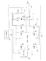
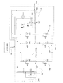
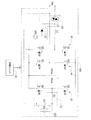
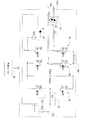
10 スイッチ
20,20’ 直流制御ユニット
L2 第2インダクタンス
D パワーダイオード
S パワースイッチ
22 第1電源スイッチ
24 第2電源スイッチ
30 第1アーム
S1 第1スイッチ
S2 第2スイッチ
40 第2アーム
S3 第3スイッチ
S4 第4スイッチ
50 第3アーム
52 出力回路
S5 第5スイッチ
S6 第6スイッチ
Lo 出力インダクタンス
Co 出力キャパシタ
60 制御ユニット
L1 第1インダクタンス
Cbus バスキャパシタ
D1〜D6 第1ダイオード〜第6ダイオード
200 負荷
Vac 交流電源
Vdc 直流電源
Vo 出力電源
Vbus バス電源
Sc 制御信号
N 巻数比
Lps 正の半周のタンク回路
Lpr 正の半周のエネルギー放出回路
Lns 負の半周のタンク回路
Lnr 負の半周のエネルギー放出回路
Ls タンク回路
Lr エネルギー放出回路
Lpc 正の半周の第1回路
Lpd 正の半周の第2回路
Lnc 負の半周の第1回路
Lnd 負の半周の第2回路
Claims (10)
- 交流電源(Vac)に接続されるスイッチ(10)、
前記スイッチ(10)に接続される第1インダクタンス(L1)、
直流電源(Vdc)と前記スイッチ(10)に接続される直流制御ユニット(20,20’)、
前記第1インダクタンス(L1)に接続される第1アーム(30)、
前記第1アーム(30)と並列に接続される第2アーム(40)、
前記第2アーム(40)と並列に接続されるバスキャパシタ(Cbus)、及び
前記第2アーム(40)と並列に接続される第3アーム(50)、を含み、
前記スイッチ(10)によって、前記第1インダクタンス(L1)が前記交流電源(Vac)に接続されるよう切り替えられると、前記交流電源(Vac)は、前記第1インダクタンス(L1)、前記第1アーム(30)及び前記第2アーム(40)を経て前記バスキャパシタ(Cbus)上のバス電源(Vbus)に変換されるとともに、前記第2アーム(40)と前記第3アーム(50)を経て出力電源(Vo)に変換され、
前記スイッチ(10)によって、前記第1インダクタンス(L1)が前記直流制御ユニット(20,20’)に接続されるよう切り替えられると、前記直流電源(Vdc)は前記直流制御ユニット(20,20’)及び前記第1インダクタンス(L1)を経て前記バス電源(Vbus)に変換されるとともに、前記第2アーム(40)と前記第3アーム(50)を経て前記出力電源(Vo)に変換されることを特徴とする無停電電源供給装置。 - 請求項1記載の無停電電源供給装置において、
前記第1アーム(30)は、
第1ダイオード(D1)と並列に接続されるとともに、前記バスキャパシタ(Cbus)の第1端子と前記第1インダクタンス(L1)に接続される第1スイッチ(S1)、及び
第2ダイオード(D2)と並列に接続されるとともに、前記第1インダクタンス(L1)と前記バスキャパシタ(Cbus)の第2端子に接続される第2スイッチ(S2)、を含み、
前記第2アーム(40)は、
第3ダイオード(D3)と並列に接続されるとともに、第1端子が前記バスキャパシタ(Cbus)の第1端子と前記交流電源(Vac)に接続される第3スイッチ(S3)、及び
第4ダイオード(D4)と並列に接続されるとともに、前記交流電源(Vac)と前記バスキャパシタ(Cbus)の第2端子に接続される第4スイッチ(S4)、を含み、
前記第3アーム(50)は、
第5ダイオード(D5)と並列に接続されるとともに、前記バスキャパシタ(Cbus)の第1端子に接続される第5スイッチ(S5)と、
第6ダイオード(D6)と並列に接続されるとともに、前記第5スイッチ(S5)と前記バスキャパシタ(Cbus)の第2端子に接続される第6スイッチ(S6)と、
前記第5スイッチ(S5)、前記第6スイッチ(S6)及び前記交流電源(Vac)に接続されて、前記出力電源(Vo)を供給する出力回路(52)、を含むことを特徴とする無停電電源供給装置。 - 請求項2記載の無停電電源供給装置において、
前記第1インダクタンス(L1)における正の半周のタンク回路(Lps)は、前記交流電源(Vac)、前記第1インダクタンス(L1)、前記第2スイッチ(S2)、前記第4ダイオード(D4)及び前記交流電源(Vac)からなり、
前記第1インダクタンス(L1)における正の半周のエネルギー放出回路は、前記交流電源(Vac)、前記第1インダクタンス(L1)、前記第1ダイオード(D1)、前記バスキャパシタ(Cbus)、前記第4ダイオード(D4)及び前記交流電源(Vac)からなり、
前記第1インダクタンス(L1)における負の半周のタンク回路(Lns)は、前記交流電源(Vac)、前記第3ダイオード(D3)、前記第1スイッチ(S1)、前記第1インダクタンス(L1)及び前記交流電源(Vac)からなり、
前記第1インダクタンス(L1)における負の半周のエネルギー放出回路(Lnr)は、前記交流電源(Vac)、前記第3ダイオード(D3)、前記バスキャパシタ(Cbus)、前記第2ダイオード(D2)、前記第1インダクタンス(L1)及び前記交流電源(Vac)からなり、
前記バスキャパシタ(Cbus)における正の半周の第1回路(Lpc)は、前記バスキャパシタ(Cbus)、前記第5スイッチ(S5)、前記出力回路(52)、前記第4スイッチ(S4)及び前記バスキャパシタ(Cbus)からなり、
前記バスキャパシタ(Cbus)における正の半周の第2回路(Lpd)は、前記出力回路(52)、前記第3ダイオード(D3)、前記バスキャパシタ(Cbus)、前記第6ダイオード(D6)及び前記出力回路(52)からなり、
前記バスキャパシタ(Cbus)における負の半周の第1回路(Lnc)は、前記バスキャパシタ(Cbus)、前記第3スイッチ(S3)、前記出力回路(52)、前記第6スイッチ(S6)及び前記バスキャパシタ(Cbus)からなり、
前記バスキャパシタ(Cbus)における負の半周の第2回路(Lnd)は、前記出力回路(52)、前記第5ダイオード(D5)、前記バスキャパシタ(Cbus)、前記第4ダイオード(D4)及び前記出力回路(52)からなることを特徴とする無停電電源供給装置。 - 請求項2記載の無停電電源供給装置において、
前記直流制御ユニット(20,20’)は、
前記直流電源(Vdc)と前記スイッチ(10)に接続される第2インダクタンス(L2)、
前記第2インダクタンス(L2)に接続されるパワーダイオード(D)、及び
前記パワーダイオード(D)と前記直流電源(Vdc)に接続されるパワースイッチ(S)、を含むことを特徴とする無停電電源供給装置。 - 請求項4記載の無停電電源供給装置において、
前記第2インダクタンス(L2)のタンク回路(Ls)は、前記直流電源(Vdc)、前記第2インダクタンス(L2)、前記パワーダイオード(D)、前記パワースイッチ(S)及び前記直流電源(Vdc)からなり、
前記第2インダクタンス(L2)のエネルギー放出回路(Lr)は、前記直流電源(Vdc)、前記第2インダクタンス(L2)、前記第1インダクタンス(L1)、前記第1ダイオード(D1)、前記バスキャパシタ(Cbus)及び前記直流電源(Vdc)からなり、
前記第1インダクタンス(L1)と前記第2インダクタンス(L2)には巻数比(N)が与えられ、前記第2インダクタンス(L2)の電圧は前記巻数比(N)で前記第1インダクタンス(L1)に結合(カップリング)されるため、前記電圧に前記巻数比(N)をかけたものが前記第1インダクタンス(L1)の電圧となることを特徴とする無停電電源供給装置。 - 請求項1記載の無停電電源供給装置において、
更に、複数の制御信号(Sc)を供給して、前記交流電源(Vac)又は前記直流電源(Vdc)が、前記第1インダクタンス(L1)、前記直流制御ユニット(20,20’)、前記第1アーム(30)、前記第2アーム(40)を経て前記バス電源(Vbus)に変換されるとともに、前記第2アーム(40)及び前記第3アーム(50)を経て前記出力電源(Vo)に変換されるよう、前記スイッチ(10)、前記直流制御ユニット(20,20’)、前記第1アーム(30)、前記第2アーム(40)及び前記第3アーム(50)を制御する制御ユニット(60)を含むことを特徴とする無停電電源供給装置。 - 交流電源(Vac)と直流電源(Vdc)に接続される直流制御ユニット(20,20’)、
前記直流制御ユニット(20,20’)に接続される第1インダクタンス(L1)、
前記第1インダクタンス(L1)に接続される第1アーム(30)、
前記第1アーム(30)と並列に接続される第2アーム(40)、
前記第2アーム(40)と並列に接続されるバスキャパシタ(Cbus)、及び
前記第2アーム(40)と並列に接続される第3アーム(50)、を含み、
前記直流制御ユニット(20,20’)によって、前記交流電源(Vac)が前記第1インダクタンス(L1)に接続されるよう制御されると、前記交流電源(Vac)は、前記第1インダクタンス(L1)、前記第1アーム(30)及び前記第2アーム(40)を経て前記バスキャパシタ(Cbus)上のバス電源(Vbus)に変換されるとともに、前記第2アーム(40)と前記第3アーム(50)を経て出力電源(Vo)に変換され、
前記直流制御ユニット(20,20’)によって、前記直流電源(Vdc)が前記第1インダクタンス(L1)に接続されるよう制御されると、前記直流電源(Vdc)は、前記第1インダクタンス(L1)と前記第1アーム(30)を経てバス電源(Vbus)に変換されるとともに、前記第2アーム(40)と前記第3アーム(50)を経て前記出力電源(Vo)に変換されることを特徴とする無停電電源供給装置。 - 請求項7記載の無停電電源供給装置において、
前記第1アーム(30)は、
第1ダイオード(D1)と並列に接続されるとともに、前記バスキャパシタ(Cbus)の第1端子と前記第1インダクタンス(L1)に接続される第1スイッチ(S1)、及び
第2ダイオード(D2)と並列に接続されるとともに、前記第1インダクタンス(L1)と前記バスキャパシタ(Cbus)の第2端子に接続される第2スイッチ(S2)、を含み、
前記第2アーム(40)は、
第3ダイオード(D3)と並列に接続されるとともに、前記バスキャパシタ(Cbus)の第1端子と前記交流電源(Vac)に接続される第3スイッチ(S3)、及び
第4ダイオードと並列に接続されるとともに、前記交流電源(Vac)と前記バスキャパシタ(Cbus)の第2端子に接続される第4スイッチ(S4)、を含み、
前記第3アーム(50)は、
第5ダイオード(D5)と並列に接続されるとともに、前記バスキャパシタ(Cbus)の第1端子に接続される第5スイッチ(S5)、
第6ダイオード(D6)と並列に接続されるとともに、前記第5スイッチ(S5)と前記バスキャパシタ(Cbus)の第2端子に接続される第6スイッチ(S6)、及び
前記第5スイッチ(S5)、前記第6スイッチ(S6)及び前記交流電源(Vac)に接続されて前記出力電源(Vo)を供給する出力回路(52)、を含むことを特徴とする無停電電源供給装置。 - 請求項7記載の無停電電源供給装置において、
前記直流制御ユニット(20,20’)は、
前記交流電源(Vac)と前記第1インダクタンス(L1)に接続される第1電源スイッチ(22)、及び
前記直流電源(Vdc)と前記第1インダクタンス(L1)に接続される第2電源スイッチ(24)、を含み、
前記第1電源スイッチ(22)が導通し、前記第2電源スイッチ(24)が導通していない場合、前記交流電源(Vac)が前記第1インダクタンス(L1)に接続され、
前記第1電源スイッチ(22)が導通せず、前記第2電源スイッチ(24)が導通している場合、前記直流電源(Vdc)が前記第1インダクタンス(L1)に接続されることを特徴とする無停電電源供給装置。 - 請求項7記載の無停電電源供給装置において、
更に、複数の制御信号(Sc)を供給して、前記交流電源(Vac)又は前記直流電源(Vdc)が、前記第1インダクタンス(L1)、前記第1アーム(30)、前記第2アーム(40)を経て前記バス電源(Vbus)に変換されるとともに、前記第2アーム(40)及び前記第3アーム(50)を経て前記出力電源(Vo)に変換されるよう、前記直流制御ユニット(20,20’)、前記第1アーム(30)、前記第2アーム(40)及び前記第3アーム(50)を制御する制御ユニット(60)を含むことを特徴とする無停電電源供給装置。
Applications Claiming Priority (2)
| Application Number | Priority Date | Filing Date | Title |
|---|---|---|---|
| TW106145459A TWI658678B (zh) | 2017-12-25 | 2017-12-25 | 不斷電電源供應裝置 |
| TW106145459 | 2017-12-25 |
Publications (2)
| Publication Number | Publication Date |
|---|---|
| JP2019115251A true JP2019115251A (ja) | 2019-07-11 |
| JP6712625B2 JP6712625B2 (ja) | 2020-06-24 |
Family
ID=63685700
Family Applications (1)
| Application Number | Title | Priority Date | Filing Date |
|---|---|---|---|
| JP2018177458A Active JP6712625B2 (ja) | 2017-12-25 | 2018-09-21 | 無停電電源供給装置 |
Country Status (4)
| Country | Link |
|---|---|
| US (1) | US10615637B2 (ja) |
| EP (1) | EP3503366B1 (ja) |
| JP (1) | JP6712625B2 (ja) |
| TW (1) | TWI658678B (ja) |
Families Citing this family (5)
| Publication number | Priority date | Publication date | Assignee | Title |
|---|---|---|---|---|
| US10944319B2 (en) * | 2018-11-30 | 2021-03-09 | Schneider Electric It Corporation | Flying battery with AC switch PFC front end for ups |
| EP3772794A1 (en) * | 2019-08-08 | 2021-02-10 | Schneider Electric IT Corporation | Coupled-inductor-based power-device circuit topology |
| CN114069819A (zh) * | 2020-08-07 | 2022-02-18 | 台达电子工业股份有限公司 | 具有三阶层切换电路的转换装置及三阶层切换电路的操作方法 |
| CN115811211A (zh) * | 2021-09-15 | 2023-03-17 | 维谛公司 | 三桥臂拓扑电路的限流方法及装置、存储介质和处理器 |
| TWI846555B (zh) * | 2023-08-01 | 2024-06-21 | 台達電子工業股份有限公司 | 可平衡能量與混合供電的電源轉換器與電源轉換方法 |
Citations (2)
| Publication number | Priority date | Publication date | Assignee | Title |
|---|---|---|---|---|
| US20080012426A1 (en) * | 2006-07-12 | 2008-01-17 | Delta Electronics, Inc. | Method of controlling an uninterruptible power supply apparatus |
| JP2009303349A (ja) * | 2008-06-11 | 2009-12-24 | Sanken Electric Co Ltd | 交流電源装置 |
Family Cites Families (11)
| Publication number | Priority date | Publication date | Assignee | Title |
|---|---|---|---|---|
| JP2940536B1 (ja) | 1998-02-09 | 1999-08-25 | 富士電機株式会社 | 無停電電源装置 |
| US6160722A (en) | 1999-08-13 | 2000-12-12 | Powerware Corporation | Uninterruptible power supplies with dual-sourcing capability and methods of operation thereof |
| US7050312B2 (en) * | 2004-03-09 | 2006-05-23 | Eaton Power Quality Corporation | Multi-mode uninterruptible power supplies and methods of operation thereof |
| JP2005354756A (ja) * | 2004-06-08 | 2005-12-22 | Fuji Electric Systems Co Ltd | 無停電電源装置 |
| US7705489B2 (en) * | 2006-09-08 | 2010-04-27 | American Power Conversion Corporation | Method and apparatus for providing uninterruptible power |
| TWI367619B (en) * | 2008-09-01 | 2012-07-01 | Delta Electronics Inc | Parallel-connectred uninterrupted power supply circuit |
| JP5486604B2 (ja) * | 2009-09-25 | 2014-05-07 | 東芝三菱電機産業システム株式会社 | 無停電電源装置 |
| US8698354B2 (en) * | 2010-11-05 | 2014-04-15 | Schneider Electric It Corporation | System and method for bidirectional DC-AC power conversion |
| CN102832688B (zh) | 2011-06-17 | 2015-05-20 | 艾默生网络能源有限公司 | 一种不间断电源 |
| US9106103B2 (en) | 2011-09-23 | 2015-08-11 | Eaton Corporation | Unintteruptible power supply systems and methods employing on-demand energy storage |
| JP6327106B2 (ja) * | 2014-01-10 | 2018-05-23 | 住友電気工業株式会社 | 変換装置 |
-
2017
- 2017-12-25 TW TW106145459A patent/TWI658678B/zh active
-
2018
- 2018-09-21 JP JP2018177458A patent/JP6712625B2/ja active Active
- 2018-09-25 US US16/141,134 patent/US10615637B2/en active Active
- 2018-09-26 EP EP18196852.0A patent/EP3503366B1/en active Active
Patent Citations (2)
| Publication number | Priority date | Publication date | Assignee | Title |
|---|---|---|---|---|
| US20080012426A1 (en) * | 2006-07-12 | 2008-01-17 | Delta Electronics, Inc. | Method of controlling an uninterruptible power supply apparatus |
| JP2009303349A (ja) * | 2008-06-11 | 2009-12-24 | Sanken Electric Co Ltd | 交流電源装置 |
Also Published As
| Publication number | Publication date |
|---|---|
| TWI658678B (zh) | 2019-05-01 |
| US10615637B2 (en) | 2020-04-07 |
| EP3503366B1 (en) | 2020-12-16 |
| JP6712625B2 (ja) | 2020-06-24 |
| EP3503366A1 (en) | 2019-06-26 |
| TW201929381A (zh) | 2019-07-16 |
| US20190199126A1 (en) | 2019-06-27 |
Similar Documents
| Publication | Publication Date | Title |
|---|---|---|
| US9093917B2 (en) | Bridgeless power factor correction circuit | |
| JP2019115251A (ja) | 無停電電源供給装置 | |
| JP5135359B2 (ja) | 低い入力電圧で使用されるチャージポンプ電子安定器 | |
| RU2541511C2 (ru) | Система электропитания для электронных нагрузок | |
| US20100295478A1 (en) | Led driving circuit | |
| CN111697847A (zh) | Weissach整流器组件 | |
| WO2013181973A1 (zh) | 一种不间断电源电路及其控制方法 | |
| TW201328118A (zh) | 不間斷電源系統 | |
| TW200836468A (en) | Primary circuit for feeding a secondary circuit | |
| CN103001313B (zh) | 一种离线式不间断电源系统 | |
| JP2015066444A (ja) | 改良型電源モジュール内蔵手術装置 | |
| CN110515446A (zh) | 一种服务器及其供电及功耗监控电路 | |
| CN110419157A (zh) | 具有电荷泵电路的驱动器 | |
| CN109104086B (zh) | 一种具有功率因数修正功能的直流对直流转换器 | |
| CN109962474B (zh) | 不断电电源供应装置 | |
| CN113632357B (zh) | 电力转换系统、用于控制电力转换系统的方法和程序 | |
| TWI451678B (zh) | 升壓轉換裝置及升壓轉換電路 | |
| CN103187746B (zh) | 一种不间断电源拓扑 | |
| CN116742934A (zh) | 交直流复合辅助电源电路及光伏逆变器 | |
| JP6444204B2 (ja) | 電力変換装置 | |
| CN108882463B (zh) | 应用于灯组的交直流切换电路 | |
| JP5830659B2 (ja) | 負荷制御装置 | |
| CN105490554A (zh) | 一种变频电源 | |
| TWI477044B (zh) | Step-down rectifier | |
| TWI725915B (zh) | 具有諧波補償之濾波電路 |
Legal Events
| Date | Code | Title | Description |
|---|---|---|---|
| A621 | Written request for application examination |
Free format text: JAPANESE INTERMEDIATE CODE: A621 Effective date: 20180921 |
|
| A977 | Report on retrieval |
Free format text: JAPANESE INTERMEDIATE CODE: A971007 Effective date: 20190926 |
|
| A131 | Notification of reasons for refusal |
Free format text: JAPANESE INTERMEDIATE CODE: A131 Effective date: 20191001 |
|
| A601 | Written request for extension of time |
Free format text: JAPANESE INTERMEDIATE CODE: A601 Effective date: 20191220 |
|
| A521 | Request for written amendment filed |
Free format text: JAPANESE INTERMEDIATE CODE: A523 Effective date: 20200226 |
|
| TRDD | Decision of grant or rejection written | ||
| A01 | Written decision to grant a patent or to grant a registration (utility model) |
Free format text: JAPANESE INTERMEDIATE CODE: A01 Effective date: 20200526 |
|
| A61 | First payment of annual fees (during grant procedure) |
Free format text: JAPANESE INTERMEDIATE CODE: A61 Effective date: 20200601 |
|
| R150 | Certificate of patent or registration of utility model |
Ref document number: 6712625 Country of ref document: JP Free format text: JAPANESE INTERMEDIATE CODE: R150 |
|
| R250 | Receipt of annual fees |
Free format text: JAPANESE INTERMEDIATE CODE: R250 |
|
| R250 | Receipt of annual fees |
Free format text: JAPANESE INTERMEDIATE CODE: R250 |
|
| R250 | Receipt of annual fees |
Free format text: JAPANESE INTERMEDIATE CODE: R250 |