JP2019118917A - Bend correction method of shape steel and manufacturing method of shape steel - Google Patents
Bend correction method of shape steel and manufacturing method of shape steel Download PDFInfo
- Publication number
- JP2019118917A JP2019118917A JP2017253533A JP2017253533A JP2019118917A JP 2019118917 A JP2019118917 A JP 2019118917A JP 2017253533 A JP2017253533 A JP 2017253533A JP 2017253533 A JP2017253533 A JP 2017253533A JP 2019118917 A JP2019118917 A JP 2019118917A
- Authority
- JP
- Japan
- Prior art keywords
- bending
- section
- rolling
- correction
- shaped steel
- Prior art date
- Legal status (The legal status is an assumption and is not a legal conclusion. Google has not performed a legal analysis and makes no representation as to the accuracy of the status listed.)
- Granted
Links
Images


Landscapes
- Metal Rolling (AREA)
- Control Of Metal Rolling (AREA)
Abstract
【課題】より正確に形鋼の曲がりを矯正する。
【解決手段】ウェブ及びウェブの高さ方向の端部に設けられたフランジを有する形鋼10のウェブ高さ方向での曲がりを矯正する方法であって、曲がり形状測定工程で得られた曲がり形状曲線に基づいて、フランジの圧延条件を決定する圧延条件決定工程を備えている。そして、圧延条件決定工程は、形鋼の長手方向に複数の区間を設定し、各区間での前記形鋼の単位長さ当たりの曲がり量の平均値に基づき、フランジの圧延条件を決定するものであり、各区間の長さについて、形鋼の長手方向の各位置での単位長さ当たりの曲がり量と、各区間での単位長さ当たりの曲がり量の平均値との誤差の総和が最小となるように各区間の長さを決定する。
【選択図】図1PROBLEM TO BE SOLVED: To correct the bending of a shaped steel more accurately.
A method of correcting a bend in a web height direction of a shaped steel 10 having a web and a flange provided at an end in the height direction of the web, the bent shape obtained in the bend shape measuring step A rolling condition determination step of determining a rolling condition of the flange based on the curve is provided. The rolling condition determination step sets a plurality of sections in the longitudinal direction of the shaped steel, and determines the rolling condition of the flange based on the average value of the bending amount per unit length of the shaped steel in each section. The sum of the errors between the amount of bending per unit length at each position in the longitudinal direction of the section and the average value of the amounts of bending per unit length for each section is the smallest. Determine the length of each section so that
[Selected figure] Figure 1
Description
本発明は、形鋼の曲がり矯正方法及び形鋼の製造方法に関し、特に、ウェブ及び該ウェブの高さ方向の端部に設けられたフランジを有するH形鋼の曲がり矯正方法及びその曲がり矯正方法を実施する曲がり矯正工程を備えた形鋼の製造方法に適用して有効な技術に関するものである。 The present invention relates to a method of correcting bending of a shape steel and a method of manufacturing a shape steel, and in particular, a method of correcting curvature of a H-shaped steel having a web and a flange provided at the end in the height direction of the web The present invention relates to an effective technique applicable to a method of manufacturing a shaped steel provided with a bending correction process for carrying out the present invention.
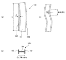
図12に示すように、形鋼としてのH形鋼100は、ウェブ101と、ウェブ101の高さ方向両側にそれぞれ設けられた2つのフランジ102,102と、を有している。このようなH形鋼は、ビームブランクやブルームなどの被圧延材を加熱炉で加熱した後、通常、ユニバーサル圧延によって製造される。ユニバーサル圧延機は、上下一対の水平ロールと、左右一対の垂直ロールとを備えた圧延機であり、被圧延材のウェブ部とフランジ部とをこれらのロールで圧下することによってH形鋼の製品形状としていく。
As shown in FIG. 12, the H-
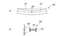
成型されたH形鋼は、熱間圧延時のフランジの圧下率差や冷却時の温度差などによって、曲がりや反りが生じる場合がある。すなわち、H形鋼を圧延製造する場合には、図12の(a)に示すように、H形鋼100に、ウェブ101の高さ方向での曲がり(曲がり量を符号δで示す)や、あるいは、図13の(a)に示すように、ウェブ101の厚さ方向での反り(反り量を符号Swで示す)が、長手方向の全体又は一部に生じる場合がある。そのため、成型したH形鋼を冷却床で冷却後に、曲がりや反りを所望の形状に矯正して製品とされる。
The formed H-section steel may be bent or warped due to the difference in the rolling reduction of the flange at the time of hot rolling or the temperature difference at the time of cooling. That is, when the H-shaped steel is rolled and manufactured, as shown in FIG. 12A, the H-
このような曲がりや反りを減少させる方法として、ユニバーサル圧延での圧延条件を調整する方法が知られている。しかしながら、H形鋼の曲がりや反りの発生には、ユニバーサル圧延での圧下のアンバランスや被圧延材の形状不良などが影響している。すなわち、H形鋼の曲がりや反りの発生には、ユニバーサル圧延機や被圧延材が有する種々の上下左右方向の非対称圧延要素が影響している。よって、これら全ての要因に対応してユニバーサル圧延機の圧延条件を微妙に調整することは非常に困難である。
そのため、圧延条件の調整でも曲がりや反りを防止できない場合は、圧延後にH形鋼を温間又は冷間で矯正することが不可欠となる。このような反りに対しては、通常、ローラー矯正機によってオンラインで矯正を行っているが、曲がりに対しては、反りと比較して矯正荷重が多大となることから、精整工程においてオフラインでプレス機による矯正を行っている。
As a method of reducing such bending or warping, a method of adjusting rolling conditions in universal rolling is known. However, the occurrence of bending or warping of H-shaped steel is affected by unbalance in reduction in universal rolling, shape defects of the material to be rolled, and the like. That is, the occurrence of bending or warping of the H-shaped steel is affected by the universal rolling mill and various asymmetric rolling elements in the vertical and horizontal directions of the material to be rolled. Therefore, it is very difficult to finely adjust the rolling conditions of the universal rolling mill in response to all these factors.
Therefore, if bending or warping can not be prevented even by adjusting the rolling conditions, it is indispensable to correct the H-shaped steel with warm or cold after rolling. For such warpage, correction is usually performed online by a roller straightening machine, but since the correction load for bending is greater compared to warpage, it is possible to use an off-line in the refinement process. We are making corrections with a press.
曲がりをプレス矯正する方法としては、プレス機によりH形鋼に対して3点曲げを行って矯正する方法が知られている(例えば特許文献1を参照)。しかしながら、プレス機による3点曲げ矯正においては、曲げ加工の支点間(受け金と当て金のピッチ)の機械的な制約により、H形鋼の先尾端の局所的な曲がりが矯正されにくいという問題や、曲げ矯正によってウェブの高さが変化するなどして寸法が規格から外れ格落ちしてしまうという問題があった。また、プレス機による3点曲げ矯正は、H形鋼の搬送を停止した状態で行われることから、曲がり矯正の処理能率が低いという問題があった。
これに対して、H形鋼が有する2つのフランジのうち、曲がりの曲率半径方向内側のフランジを圧延することにより、曲がりを矯正する方法が知られている(例えば特許文献2を参照)。
As a method of press-correcting bending, there is known a method of performing three-point bending on an H-shaped steel by a press machine to correct it (see, for example, Patent Document 1). However, in three-point bending correction with a press machine, it is said that local bending of the front end of H-section steel is difficult to be corrected due to the mechanical restriction between the supporting points of bending (the pitch between the receiver and the latch). There has been a problem that the dimensions may fall out of the standard due to a change in the height of the web due to bending correction or the like. In addition, since the three-point bending correction by the press machine is performed in a state in which the conveyance of the H-shaped steel is stopped, there is a problem that the processing efficiency of the bending correction is low.
On the other hand, the method of correcting a curve is known by rolling the flange of the curvature radius direction radial direction of bending among two flanges which H section steel has (for example, refer patent document 2).
この方法は、フランジをウェブとは反対側の面から支持する支持ロールと、ウェブの高さ方向端部からウェブの両面側にそれぞれ張り出す両フランジ部(ここでは右フランジ部及び左フランジ部と言う)を有するフランジをウェブ側の面から押圧して、右フランジ部と左フランジ部とをそれぞれ支持ロールとの間で挟圧する一対の矯正ロールと、を用い、フランジ内外の対向する両ロール間の距離を所定の間隔に設定して、あるいは所定の圧延荷重を負荷して、フランジを挟圧する曲がり矯正方法である。 In this method, a support roll for supporting the flanges from the side opposite to the web, and both flanges (here, right flange and left flange) respectively projecting from the height direction end of the web to both sides of the web Using a pair of correction rolls which press the flange having the above from the surface on the web side and press the right flange portion and the left flange portion between the support rolls respectively, Is a bending correction method in which the flange is pinched by setting the distance of at a predetermined interval or applying a predetermined rolling load.
この圧延矯正方法は、H形鋼を搬送しながら曲がり矯正することができるので、前述のプレス矯正方法に比べると曲がり矯正の処理能率の面では有利である。すなわち、この圧延方式の曲がり矯正設備を既存のH形鋼製造設備のオンライン工程に組み入れてH形鋼の曲がりを矯正すれば、オフライン設備の場合と比べて材料の取り込みや払い出し、その他付帯の材料ハンドリングが省略できるとともに、リードタイムを短縮することができる。 This rolling correction method can correct bending while conveying an H-section steel, and therefore is advantageous in terms of processing efficiency of bending correction as compared to the above-described press correction method. That is, if this rolling correction equipment is incorporated into the on-line process of the existing H-shaped steel manufacturing equipment and the bending of the H-shaped steel is corrected, material intake and discharge, and other incidental materials compared to the offline equipment. Handling can be omitted and lead time can be shortened.
また、この圧延矯正方法の、より具体的な方法として、特許文献3が挙げられる。これは、形鋼の長手方向にわたり、該形鋼の上記ウェブ高さ方向の曲がり形状曲線を得る曲がり形状測定工程と、該曲がり形状測定工程で得られた曲がり形状曲線に基づいて、フランジの圧延条件を決定する圧延条件決定工程と、該圧延条件決定工程により決定された圧延条件にしたがい、上記長手方向にわたって上記形鋼のフランジを圧延する圧延矯正工程と、を備える、形鋼の曲がり矯正方法である。
Moreover,
そして、圧延条件の決定工程では、得られた曲がり量曲線を複数の長手方向の単位領域に分割し、各単位領域における単位長さ当たりの曲がり量の平均値をそれぞれ算出する曲がり量曲線分割工程と、各単位領域における上記平均値と、予め設定してある曲がり量と該曲がり量での曲がりを矯正するための圧延条件との関係から、長手方向の上記各単位領域についての圧延条件を決定する単位領域圧延条件決定工程とを備えている。
また、この「複数の長手方向の単位領域分割」については、
(A1):各単位領域内における単位長さ当たりの曲がり量の最大値と最小値との差が所定の基準値以下となるように行う、
(A2):製品長さに応じて、各単位領域を均等に分割する、
ことが開示されている。
Then, in the step of determining the rolling conditions, the curve curve dividing step of dividing the obtained curve of curve amount into a plurality of unit regions in the longitudinal direction, and calculating the average value of the amount of curve per unit length in each unit region. The rolling conditions for each unit area in the longitudinal direction are determined from the relationship between the above average value in each unit area, the pre-set bending amount, and the rolling conditions for correcting the bending amount. And a unit area rolling condition determining step.
Also, with regard to this “multiple unit area division in the longitudinal direction”,
(A1): The difference between the maximum value and the minimum value of the amount of bending per unit length in each unit area is made to be equal to or less than a predetermined reference value.
(A2): Divide each unit area equally according to the product length,
Is disclosed.
上述した従来のプレス矯正方法では、H形鋼における曲がり矯正を施す位置(以下、「矯正位置」と記すこともある)や矯正量は、作業員が目視により判断していた。そのため、正確で効率の良い曲がり矯正を行うことができない場合があった。
また、上述した特許文献1に開示される圧延矯正方法では、曲がりの曲率半径方向内側のフランジを圧延することにより、H形鋼を搬送しながら曲がり矯正することができるが、曲がり矯正を行う上での矯正ロールの圧下量をどのように制御すれればよいかについて、具体的に開示された例はなく、この方法による曲がり矯正の具現化のためには、さらなる工夫が必要であった。
一方、特許文献3に開示される圧延矯正方法は、矯正を行う製品の長手方向で複数の区間を設け、その各区間での曲がりの実態(平均値)に応じて矯正条件、すなわち圧延条件を決定するものであり、曲がりの矯正を効率的に行える技術であった。
In the conventional press correction method described above, the operator visually determines the position (hereinafter, also referred to as "correction position") and the correction amount to be subjected to the bending correction in the H-shaped steel. Therefore, there were cases where it was not possible to perform accurate and efficient bend correction.
In addition, in the rolling correction method disclosed in
On the other hand, in the rolling correction method disclosed in
しかしながら、その矯正区間長について、
(B1):各単位領域内における単位長さ当たりの曲がり量の最大値と最小値との差が所定の基準値以下となるように行う場合は、曲がりの形態によっては、区間の数が非常に大きくなってしまい、矯正機側がこの設定を行えない場合が多発する、
(B2):製品長さに応じて、各単位領域を均等に分割する場合も、曲がりの形態によっては、各区間での平均値とその箇所での実際の曲がり量との差が大きく、その箇所で必要な矯正条件とは、かけ離れた矯正を行う場合が頻発して、曲がりの矯正効果が発揮できない、
という問題があった。
そこで、本発明は上記従来技術の課題に着目してなされたものであり、本発明の目的は、より正確に形鋼の曲がり矯正を行うことが可能な技術を提供することにある。
However, regarding the correction section length,
(B1): When the difference between the maximum value and the minimum value of the amount of bending per unit length in each unit area is equal to or less than a predetermined reference value, the number of sections is very large depending on the form of bending. And the correction machine often can not make this setting.
(B2): Even when the unit areas are equally divided according to the product length, depending on the form of bending, the difference between the average value in each section and the actual amount of bending at that point is large, With the necessary correction conditions in the part, the case of making a distant correction frequently occurs, and the correction effect of bending can not be exhibited.
There was a problem that.
Then, this invention was made paying attention to the subject of the said prior art, and the objective of this invention is providing the technique which can perform bending correction of a shaped steel more correctly.
上記目的を達成するため、本発明の一態様に係る形鋼の曲がり矯正方法は、ウェブ及び上記ウェブの高さ方向の端部に設けられたフランジを有する形鋼の上記ウェブ高さ方向での曲がりを矯正する方法であって、上記形鋼の長手方向に亘り、上記形鋼の上記ウェブ高さ方向の単位長さ当たりの曲がり形状曲線を得る曲がり形状測定工程と、上記曲がり形状測定工程で得られた曲がり形状曲線に基づいて、上記フランジの圧延条件を決定する圧延条件決定工程と、上記圧延条件決定工程により決定された圧延条件に従い、上記形鋼の長手方向に亘って上記フランジを圧延する圧延矯正工程とを備える。そして、上記圧延条件決定工程は、上記形鋼の長手方向に複数の区間を設定し、上記各区間での上記形鋼の単位長さ当たりの曲がり量の平均値に基づき、上記フランジの圧延条件を決定するものであり、上記各区間の長さについて、上記形鋼の長手方向の各位置での単位長さ当たりの曲がり量と、上記各区間での単位長さ当たりの曲がり量の平均値との誤差の総和が最小となるように上記各区間の長さを決定する。 In order to achieve the above object, according to one aspect of the present invention, there is provided a method of correcting bending of a shaped steel, comprising a web and a flange provided at an end in a height direction of the web in the height direction of the shaped steel. A method of correcting a bend, comprising: a bend shape measuring step of obtaining a bend shape curve per unit length in the web height direction of the shape steel along the longitudinal direction of the shape steel; The flange is rolled along the longitudinal direction of the section steel according to the rolling condition determination step of determining the rolling condition of the flange based on the obtained curved shape curve and the rolling condition determined by the rolling condition determination step And a rolling correction process. The rolling condition determination step sets a plurality of sections in the longitudinal direction of the section steel, and the rolling conditions of the flange based on the average value of the bending amount per unit length of the section steel in each section. For the length of each section, an average value of the amount of bending per unit length at each position in the longitudinal direction of the section steel and the amount of bending per unit length in each section The length of each section is determined so as to minimize the sum of errors between
また、本発明の一態様に係る形鋼の矯正方法は、ウェブ及び上記ウェブの高さ方向の端部に設けられたフランジを有する形鋼の上記ウェブ高さ方向での曲がりを矯正する方法であって、上記形鋼の長手方向に亘り、上記形鋼の上記ウェブ高さ方向の単位長さ当たりの曲がり形状曲線を得る曲がり形状測定工程と、上記曲がり形状測定工程で得られた曲がり形状曲線に基づいて、上記フランジの圧延条件を決定する圧延条件決定工程と、上記圧延条件決定工程により決定された圧延条件に従い、上記形鋼の長手方向に亘って上記フランジを圧延する圧延矯正工程とを備える。そして、上記圧延条件決定工程は、上記形鋼の長手方向に複数の区間を設定し、上記各区間での上記形鋼の単位長さ当たりの曲がり量の平均値に基づき、上記フランジの圧延条件を決定するものであり、上記各区間の長さについて、上記形鋼の長手方向の各位置での単位長さ当たりの曲がり量と、上記各区間での単位長さ当たりの曲がり量の平均値との誤差の総和が許容値以下となるように上記各区間の長さを決定する。
また、本発明の一態様に係る形鋼の製造方法は、上記形鋼の曲がり矯正方法を実施する曲がり矯正工程を備える。
In addition, according to one aspect of the present invention, there is provided a method of correcting a bend in a web in a height direction of a web having a web and a flange provided at an end of the web in the height direction. A bending shape measuring step for obtaining a bending shape curve per unit length in the web height direction of the shape steel in the longitudinal direction of the shape steel, and the bending shape curve obtained in the bending shape measurement process A rolling condition determination step of determining the rolling condition of the flange, and a rolling correction step of rolling the flange over the longitudinal direction of the section according to the rolling conditions determined by the rolling condition determination step; Prepare. The rolling condition determination step sets a plurality of sections in the longitudinal direction of the section steel, and the rolling conditions of the flange based on the average value of the bending amount per unit length of the section steel in each section. For the length of each section, an average value of the amount of bending per unit length at each position in the longitudinal direction of the section steel and the amount of bending per unit length in each section The length of each section is determined so that the sum of the errors between
Moreover, the manufacturing method of the section steel which concerns on 1 aspect of this invention is equipped with the bending correction process of enforcing the bending correction method of the said section steel.
本発明の一態様によれば、より正確に形鋼の曲がりを矯正することが可能となる。 According to one aspect of the present invention, it is possible to correct the bending of the shaped steel more accurately.
以下、図面を参照して、本発明の一実施形態に係る形鋼の曲がり矯正方法及びその曲がり矯正方法を実施する曲がり矯正工程を備えた形鋼の製造方法について説明する。なお、発明の実施形態を説明するための全図において、同一機能を有するものは同一符号を付け、その繰り返しの説明は省略する。
本発明の一実施形態に係るH形鋼の曲がり矯正方法を説明する前に、その曲がり矯正方法を実施する曲がり矯正設備を備えたH形鋼製造設備(H形鋼製造ライン)について説明する。
Hereinafter, with reference to the drawings, a method of correcting bending of a shaped steel according to an embodiment of the present invention and a method of manufacturing a shaped steel provided with a bending correction process for implementing the method of correcting bending will be described. Note that components having the same function are denoted by the same reference symbols throughout the drawings for describing the embodiments of the invention, and the repetitive description thereof will be omitted.
Before describing the method of correcting bending of H-section steel according to one embodiment of the present invention, an H-shaped steel manufacturing facility (H-shaped steel manufacturing line) equipped with a bending correction facility for implementing the method of correcting bending will be described.
<H形鋼製造設備>
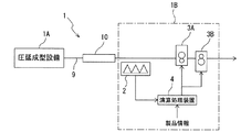
図1に示すように、形鋼であるH形鋼の製造に用いられるH形鋼製造設備(製造ライン)1は、ブルームやビームブランクなどの被圧延材を圧延してH形鋼10の形状に成型する圧延成型設備1Aと、この圧延成型設備1Aで成型されたH形鋼10の曲がりを矯正する曲がり矯正設備1Bとを備えている。このH形鋼製造設備1は、H形鋼10の製造方法において、圧延成型設備1Aで圧延成型工程を実施し、曲がり矯正設備1Bで曲がり矯正工程を実施する。すなわち、本発明の一実施形態に係るH形鋼10の製造方法は、被圧延材を圧延してH形鋼10の形状に成型する圧延成型工程と、この圧延成型工程で成型されたH形鋼10の曲がりを矯正する曲がり矯正工程とを備えている。そして、曲がり矯正工程では、本発明の一実施形態に係るH形鋼10の曲がり矯正方法が実施される。
<H-shaped steel manufacturing facility>
As shown in FIG. 1, H-shaped steel manufacturing equipment (production line) 1 used for manufacturing H-shaped steel which is a shaped steel is a shape of H-shaped
<圧延成型設備>
圧延成型設備1Aは、連続加熱炉、酸化皮膜除去装置、粗圧延機、トングカットソー、中間圧延機、仕上げ圧延機、ホットソー、冷却床(クーリングベット)などを備えている。この圧延成型設備1Aで成型されたH形鋼10は、冷却床で冷却された後に、H形鋼製造設備1の搬送ライン9により圧延成型設備1Aから曲がり矯正設備1Bに導入される。そして、H形鋼10は、この曲がり矯正設備1Bにおいて、例えば冷間で曲がり矯正されて所望の形状の製品とされた後、搬送ライン9により下流側の設備に送られる。中間圧延機、仕上げ圧延機としては、例えばユニバーサル圧延機が用いられる。
<Rolling and forming equipment>
The rolling and forming equipment 1A includes a continuous heating furnace, an oxide film removing device, a rough rolling mill, a tongue cut, an intermediate rolling mill, a finish rolling mill, a hot saw, a cooling bed (cooling bed), and the like. The H-shaped
<曲がり矯正設備>
曲がり矯正設備1Bは、形鋼としてウェブ及び該ウェブの高さ方向の端部に設けられたフランジを有するH形鋼10のウェブの高さ方向での曲がりを矯正する設備であり、H形鋼10を製造するH形鋼製造設備1のオンライン工程に組み入れられている。すなわち、曲がり矯正設備1Bは、H形鋼10の製造に係る他の設備と直列をなして配置されている。
曲がり矯正設備1Bは、前段の圧延成型設備で成型されて曲がりを矯正する前のH形鋼10の曲がりを測定する曲がり測定装置2と、この曲がり測定装置2の測定結果に対して演算処理を行う演算処理装置4と、この演算処理装置4による演算処理結果に基づいてH形鋼10のフランジ12(図2参照)を圧延してH形鋼10の曲がりを矯正する2つの曲がり矯正機3A,3Bとを備えている。
<Curve correction equipment>
The bending
<曲がり測定装置>
曲がり測定装置2の種類や測定方法が特に限定されるものではないが、例えばH形鋼10を搬送中にH形鋼10のウェブ11とは反対側のフランジ側面(フランジ外面)或いは、H形鋼10のウェブ11側のフランジ側面(フランジ内面)に対向するように配置したレーザ距離計にて、フランジ外面、あるいはフランジ内面までの距離を測定することで実施できる。
H形鋼10を搬送ライン9上で停止させた状態として、レーザ距離計をH形鋼10のフランジ外面あるいはフランジ内面に対向配置しつつ、レーザ距離計をH形鋼10の長手方向に走行させることで、H形鋼10の長手方向に沿ってレーザ距離計からフランジ外面あるいはフランジ内面までの距離を計測するようにしてもよい。曲がり測定装置2においては、H形鋼10に曲がりが生じている長手方向領域、曲がり方向、及び曲がり量が測定されるようになっている。
<Curve measurement device>
The type and measuring method of the
With the H-
ここで、本発明における「曲がり」とは、図12を参照して説明すると、ウェブ及び該ウェブの高さ方向の端部に設けられたフランジを有する形鋼において、ウェブの高さ方向での曲がりを意味する。H形鋼(製品)の全長Lの曲がり量δは図12(a)のように表される。製品の単位長さ当たりの曲がり量δ0は図12(c)のように表される。本明細書では、曲がりの方向によって正負の符号をつけている。
また、H形鋼10に生じる曲がりは種々のパターンがあり、例えば、図12(a)のように、H形鋼の全長Lでほぼ一様に一方向に曲がっている場合や、図12(c)に示すように、長手方向で曲がりの方向が変わってS字曲がりになっている場合や、このほかに、長手方向の一部の領域のみ(例えば端部のみ)に曲がりが生じている場合などの曲がり形状パターンがある。
Here, the “bending” in the present invention is, as described with reference to FIG. 12, in a section steel having a web and a flange provided at the end in the height direction of the web, in the height direction of the web. It means a curve. The bending amount δ of the total length L of the H-shaped steel (product) is represented as shown in FIG. 12 (a). The amount of bending δ 0 per unit length of the product is expressed as shown in FIG. 12 (c). In the present specification, positive and negative signs are given depending on the direction of bending.
In addition, the bending that occurs in the H-
<曲がり矯正機>
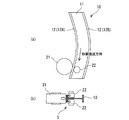
曲がり矯正機3A,3Bの種類や圧延方法は、ロールを用いてフランジをH形鋼の長手方向に圧延する方式の矯正機を用いることができる。すなわち、図2(a)及び(b)に示すように、曲がり矯正機3A,3Bは、フランジ12のウェブ11側の面とは反対側の面(フランジ外面)に対して配置され、フランジ12をフランジ外面側から支持する支持ロール21と、フランジ12のウェブ11側の面(フランジ内面)に対向して配置され、ウェブ11の高さ方向の端部からそれぞれウェブ11の高さ方向と垂直に張出す両フランジ部(ここでは右フランジ部及び左フランジ部と言う)をそれぞれ押圧する一対の矯正ロール22,22と、を備えている。曲がりの曲率半径方向内側のフランジ12(図2では左側のフランジ)を支持ロール21と矯正ロール22.22とで挟圧し、所定の圧延条件で圧延すれば、曲がりの曲率半径方向内側のフランジ12が延伸されるため、曲がりが矯正される。
<Curve Corrector>
The type and bending method of the
2つの曲がり矯正機3A,3Bのうち一方の曲がり矯正機3Aは、2つのフランジ12,12のうちの一方に対して圧延を行うものであり、他方の曲がり矯正機3Bは、他方のフランジ12に対して圧延を行うものである。H形鋼10に生じる曲がりには、上述したように種々のパターンがあるが、この実施形態のように2台の曲がり矯正機3A,3Bを組み合わせた設備構成であれば、どのような曲がり形状パターンのH形鋼であっても、曲がりを矯正することができる。
One of the two
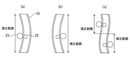
例えば、図3(a),(b)のような弓形状(皿形、逆皿形)に湾曲したH形鋼であれば、その曲がりの向きが何れであっても、2台の曲がり矯正機3A,3Bの何れか一方を用いて矯正することができるし、図3(c)のようなS字状に湾曲したH形鋼であれば、2台の曲がり矯正機3A,3Bの両方を用いて矯正することができる。
また、曲がり矯正機に付帯して、H形鋼を長手方向に反転、若しくは表裏に反転する反転機構があれば、曲がりの形態に応じて反転を加えることで、曲がり矯正機は1台のみとすることもできる。
For example, in the case of an H-shaped steel curved in an arch shape (dish shape, inverted dish shape) as shown in FIGS. 3 (a) and 3 (b), two bending corrections are made regardless of the direction of the bending. It is possible to correct using either one of the
In addition, if there is a reversing mechanism that flips the H-shaped steel in the longitudinal direction or flips it back to the front and back in addition to the bend corrector, by adding the reverse according to the form of the bend, only one bend corrector is required. You can also
なお、曲がり矯正設備1B及び圧延成型設備1AにおけるH形鋼10の姿勢は、特に限定されるものではないが、搬送時の安定性から、ウェブ11が水平をなし、フランジ12,12が鉛直をなす姿勢(以下「H姿勢」と記すこともある)とすることが好ましい。したがって、曲がり矯正時もH姿勢で圧延することが、オンライン設備としての信頼性から好ましい。ただし、ウェブ11が鉛直をなし、フランジ12,12が水平をなす姿勢(いわゆるI姿勢)とすることもできる。
The posture of the H-shaped
<H形鋼の矯正方法>
次に、圧延成型設備1A(圧延成型工程)で製造されたH形鋼10の曲がりを、曲がり矯正設備1B(曲がり矯正工程)によってオンラインで矯正する方法について説明する。
本発明の一実施形態に係るH形鋼の曲がり矯正方法は、H形鋼10の長手方向に亘り、H形鋼10のウェブ高さ方向の単位長さ当たりの曲がり形状曲線を得る曲がり形状測定工程と、曲がり形状測定工程で得られた曲がり形状曲線に基づいて、フランジ12の圧延条件を決定する圧延条件決定工程と、圧延条件決定工程により決定された圧延条件に従い、H形鋼10の長手方向に亘ってフランジ12を圧延する圧延矯正工程を備えている。そして、フランジ12の圧延条件を決定する圧延矯正工程は、H形鋼10の長手方向に複数の矯正区間を設定し、各区間でのH形鋼10の単位長さ当たりの曲がり量の平均値に基づき、フランジ12の圧延条件を決定するものである。
<H-shaped steel correction method>
Next, a method of correcting the bending of the H-shaped
According to an embodiment of the present invention, a method of correcting bending of an H-section steel is to obtain a bending shape curve per unit length in the web height direction of the H-
具体的には、圧延成型設備1Aの冷却床で冷却されたH形鋼10は、H形鋼製造設備1の搬送ライン9によって精整工程の曲がり矯正設備1Bに搬送される。曲がり矯正設備1Bに搬送されたH形鋼10は、まず、曲がり矯正機3Aの入側に設置された曲がり測定装置2に送られる。そして、この曲がり測定装置2で長手方向全域(全長)についての曲がりが測定され、曲がりが生じている長手方向領域、曲がり方向、及び曲がり量が測定される。そして、この測定結果に対して演算処理装置4によって演算処理が施され、その演算処理結果が演算処理装置4から曲がり矯正機3A,3Bに送られる。なお、この演算処理装置4での演算処理の詳細については、後述する。また、曲がり測定及び曲がり矯正は、通常はH形鋼10の全長について行われるが、長手方向の一部の領域のみ(例えは端部のみ)について行ってもよい。
Specifically, the H-shaped
H形鋼10の曲がりの測定が終了したら、H形鋼10は曲がり矯正機3A,3Bに送られ、曲がり矯正機3Aにおいて一方のフランジ12に対して圧延が施され、続いて曲がり矯正機3Bにおいて他方のフランジ12に対して圧延が施される。これらの圧延は、上記演算処理結果に基づいて設定された矯正条件で行われるようになっている。すなわち、曲がりが生じている長手方向領域、曲がり方向、及び曲がり量に応じて、圧延を施す長手方向領域、圧延条件が逐次変更されるようになっている。よって、曲がりが生じていない長手方向領域には圧延は施されない。また、曲がりが生じていても、曲がりの曲率半径方向外側のフランジ12に対して圧延は施されない。
When the measurement of the bending of the H-shaped
このようにして曲がり矯正され、所望の形状の製品とされたH形鋼10は、その後の工程、例えば反りの矯正を行うローラー矯正工程や検査工程に送られる。
このように、本実施形態の曲がり矯正設備1Bは、既存のH形鋼製造設備1に設置することが可能であり、H形鋼製造設備1のオンライン工程に組み入れてオンラインでH形鋼10の曲がりを矯正することが可能であるので、効率良くH形鋼10の曲がりを矯正することができる。また、オフラインで曲がり矯正を行う場合と比べて、材料(H形鋼)の取り込みや払い出し、その他付帯の材料ハンドリング(例えばクレーン作業)を省略できるとともに、製品出荷までのリードタイムを短縮することができる。さらに、材料ハンドリングに伴う当て疵も低減することができる。さらに、矯正位置及び矯正量(圧延条件)の設定は、目視による曲がり量の判断結果に基づくものではなく、曲がり測定装置2を用いた曲がり測定に基づいて矯正位置と矯正量を決定するので、曲がり矯正の正確性や効率が優れている。
The H-shaped
As described above, the bending
<曲がり形状に基づく矯正条件の決定方法>
次に、曲がり形状の測定結果に基づいて、演算処理装置4によって矯正(圧延)条件を決定する方法について説明する。
図4は曲がり測定装置2で測定したH形鋼10の長手方向の曲がり形状の一例を示す図であり、(a)はH形鋼10の全長の曲がりプロフィールを示し、(b)は単位長さ当たりの曲がり量(この例では1m当たりの曲がり量)を示している。
曲がり測定装置2によってH形鋼10の曲がりを測定すると、曲がりが生じている長手方向領域、曲がり方向、及び曲がり量が測定され、これを演算処理装置4で処理すると、図4(a)に示す曲がり形状曲線及び図4(b)に示す曲がり量曲線が得られる。この曲がり形状曲線は、H形鋼10の形状を写し取った曲線、いわゆるプロフィールデータである。図4(a)の一例の場合は、H形鋼10の全長が16mであり、全長における曲がり量は24.5mmである。なお、曲がり測定装置2による曲がり測定においては、異常値等が測定される場合があるので、必要により、異常値等の除去処理を施してから曲がり形状曲線を得ることが好ましい。
<Method of Determining Correction Condition Based on Curved Shape>
Next, a method of determining the correction (rolling) condition by the
FIG. 4 is a view showing an example of the bending shape in the longitudinal direction of the H-
When the bending of the H-shaped
この実施形態の曲がり矯正においては、矯正を行う製品としてのH形鋼10に対して、H形鋼10の長手方向に複数の矯正区間を設定する。図5に示す一例では6つの区間を設定している。そして、この各区間について、その区間での単位長さ当たりの曲がり量の平均値を求める。この単位長さ当たりの曲がり量の平均値に基づいて、各区間に対する矯正目標荷重を算出し、曲がり矯正機3A,3Bにその条件を転送する。製品情報として、矯正を行うH形鋼のサイズ、鋼種により、曲がり量に対する矯正荷重の関係式を予め定めておくことで、矯正目標荷重を決定することができる。曲がり矯正機3A,3Bはこの条件を受け取り、搬送されるH形鋼(形鋼製品)10の長手方向位置をトラッキングしつつ、この各区間に対する目標荷重に従い矯正を行う。
In the bend correction of this embodiment, a plurality of correction sections are set in the longitudinal direction of the H-shaped
ここで、図5の一例のように各矯正区間の長さを設定した場合、単位長さ当たりの曲がり量の変化が急峻となる区間については、その区間の単位長さ当たりの曲がり量の平均値と、各個の値(実際の曲がり量)とで大きな誤差が生じる。この区間について、平均値から矯正荷重を設定すると、矯正荷重が過大になる部位と過小になる部位が生じ、結果として、曲がりの矯正がうまく行えない場合が生じる。 Here, when the length of each correction section is set as in the example of FIG. 5, for a section where the change in the amount of bend per unit length is sharp, the average of the amount of bend per unit length in that section A large error occurs between the value and each individual value (the actual amount of bending). When the correction load is set from the average value in this section, a part where the correction load is excessive and a part where the correction load is too small are generated, and as a result, the correction of the bend may not be successfully performed.
この問題を回避する方法として、
(C1):長手方向に設定する矯正区間の数を大きくする(究極的には、各部位毎の曲がりに応じて、リアルタイムに矯正荷重を変更していく)、
(C2):特開2014−140898号公報に開示されるように、各単位領域(すなわち各区間)内における単位長さ当たりの曲がり量の最大値と最小値との差が基準値を超えるところで区間を区切る、
という方法が挙げられる。
しかしながら、上記(C1)の方法を実現するためには、長手方向に多くの矯正区間を設定する必要がある。そして、これを実現するために演算処理装置から細やかに曲がり矯正機に指令(目標荷重)を伝送し、曲がり矯正機はこれを随時受け取って荷重を設定する必要がある。このため、設備として非常に複雑になり、設備投資額が大きくなってしまう。
As a way to avoid this problem
(C1): Increase the number of correction sections set in the longitudinal direction (ultimately, change the correction load in real time according to the bending of each part),
(C2): As disclosed in Japanese Patent Laid-Open No. 2014-140898, where the difference between the maximum value and the minimum value of the amount of bending per unit length in each unit area (that is, each section) exceeds the reference value Divide the interval,
The method is called.
However, in order to realize the above method (C1), it is necessary to set many correction sections in the longitudinal direction. And in order to realize this, a command (target load) is finely transmitted from the arithmetic processing unit to the straightening machine, and the straightening machine needs to receive this at any time to set the load. As a result, the equipment becomes very complicated and the amount of capital investment increases.
また、上記(C2)の方法では、曲がり形態によって区分する区間数が変化することになるが、曲がり形態によっては、設備が設定できる区間数を超過する場合があり、上記(C1)の方法と同様の問題があった。
そこで、この実施形態では、例えば以下のようにして矯正区間長の設定を行う。
まず、図5に示したように、H形鋼10の長手方向に複数の矯正区間を設定する。図5の一例では、矯正区間の数は6である。
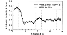
次に、各区間での単位長さ当たりの曲がり量の平均値を算出する。そして、図6に示すように、算出した各区間での単位長さ当たりの曲がり量の平均値と、その各箇所の曲がり量との差を誤差とし、H形鋼10の全長に亘る誤差の総和を誤差面積Sとして求める。図6の網掛け領域が誤差面積Sである。
Further, in the method (C2) above, the number of sections to be divided changes depending on the form of bending, but depending on the form of bending, the number of sections that can be set by equipment may exceed the number of sections. There was a similar problem.
Therefore, in this embodiment, the correction section length is set as follows, for example.
First, as shown in FIG. 5, a plurality of correction sections are set in the longitudinal direction of the H-
Next, the average value of the amount of bending per unit length in each section is calculated. Then, as shown in FIG. 6, the difference between the average value of the amount of bending per unit length calculated in each section and the amount of bending at each point is an error, and the error over the entire length of the H-
この誤差面積Sは、下記の式(1)に示すように、各区間の長さx1,x2,……,x6を変数とする関数として表すことができる。
S=f(x1,x2,……,x6) ……(1)
すなわち、誤差面積Sが最小となるx1,x2,……x6が、適正な各区間の長さであり、そのx1,x2,……x6の値は、演算処理装置4を用いて、例えば最急降下法などのアルゴリズムを活用することで求めることができる。
The error area S can be expressed as a function having the lengths x1, x2,..., X6 of the sections as variables, as shown in the following equation (1).
S = f (x1, x2, ..., x6) ... (1)
That is, x1, x2,... X6 where the error area S is minimum are the lengths of the appropriate sections, and the values of x1, x2,. It can be determined by utilizing an algorithm such as a sudden drop method.
最急降下法を使う場合は、x1を微小に変化させたときの誤差面積Sの変化量を∂S/∂×1として求め、次いでx2を微小に変化させたときの誤差面積Sの変化量を∂S/∂×2として求め、以下、同様にx3〜x6を微小に変化させたときの誤差面積Sの変化量を∂S/∂×2〜6として順次求める。そして、これらの偏微分の大きさに応じて、各区間長さx1,x2,……,x6を変化させていく。
図6の初期の区間長では誤差の平均値(誤差面積S/全区間長)が0.16mm程度であった。これに対し、図7のように区間長を最適化することにより、誤差の平均値を0.12mm程度にまで低減できた。
When using the steepest descent method, change amount of error area S when x1 is changed minutely is obtained as ∂S / ∂ × 1 and then change amount of error area S when x2 is changed minutely The variation amount of the error area S when x3 to x6 are minutely changed is determined sequentially as ∂S / ∂ × 2 to 6 similarly. The section lengths x1, x2,..., X6 are changed in accordance with the magnitudes of these partial derivatives.
In the initial section length of FIG. 6, the average value of errors (error area S / total section length) was about 0.16 mm. On the other hand, the average value of the errors could be reduced to about 0.12 mm by optimizing the section length as shown in FIG.
<一実施形態の効果>
以上のように、本発明の一実施形態に係るH形鋼10の矯正方法では、H形鋼10の長手方向の各位置での単位長さ当たりの曲がり量と、各区間での単位長さ当たりの曲がり量の平均値との誤差の総和が最小となるように、この各区間の長さを決定するので、誤差の平均値を図6から図7のように低減することができる。このため、上述した従来の上記(C1)の「長手方向に設定する矯正区間の数を大きくする」方法や上記(C2)の「各単位領域内における単位長さ当たりの曲がり量の最大値と最小値との差が基準値を超えるところで区間を区切る」方法と比較して、単位長さ当たりの曲がり量の変化が急峻となる区間においても、その区間の単位長さ当たりの曲がり量平均値と、各個の曲がり量との誤差を小さくすることができるので、H形鋼10の曲がり矯正を実際の曲がりの実態に応じてより正確に行うことができる。
<Effect of one embodiment>
As mentioned above, in the correction method of
また、矯正区間数を徒に増やすことなく、予め数が設定された矯正区間の長さを最適化して誤差の平均値を低減できるので、H形鋼10の曲がり矯正を実際の曲がりの実態に応じてより効率的に行うことができる。
また、矯正区間数を徒に増やす必要がないので、曲がり矯正設備の複雑化を抑制することができる。
したがって、本発明の一実施形態に係るH形鋼10の矯正方法によれば、簡便な曲がり矯正設備で、より正確にかつ効率よくH形鋼10の曲がり矯正を行うことができる。
In addition, since the average value of errors can be reduced by optimizing the length of the pre-set correction section without intentionally increasing the number of correction sections, it is possible to correct the bending of H-
In addition, since it is not necessary to increase the number of correction sections, it is possible to suppress the complication of the bend correction equipment.
Therefore, according to the method of correcting the H-shaped
また、本発明の一実施形態に係るH形鋼10の曲がり矯正方法は、H形鋼10の製造方法の曲がり矯正工程で実施される。したがって、本発明の一実施形態に係るH形鋼10の製造方法では、曲がり矯正工程において、より正確にかつ効率よくH形鋼10の曲がり矯正を行うことができるので、H形鋼10の歩留まり(製品取得率)の向上を図ことができる。
なお、矯正区間の長さが極端に短いと、曲がり矯正機3A,3Bの圧延による曲がり矯正効果が発揮できなくなることがある。したがって、曲がり矯正効果が発揮できる長さの許容値を予め定め、この予め定めた許容値以上となるように各区間の長さを決定することが好ましい。長さの許容値としては、曲がり矯正機3A,3Bの性能にもよるが、例えば1000mm程度である。
Further, the method of correcting the bending of the H-shaped
In addition, when the length of the correction | amendment area is extremely short, the bending correction effect by rolling of bending
(実 施 例)
以下に、本実施形態の実施例及び比較例を示す。なお、本実施形態は下記の実施例に限定されるものではない。
この実施例では、圧延で許容値以上の曲がりが発生していたH形鋼(呼称寸法でH900×300×16×28,長さ12m)について、上述した実施形態でのH形鋼の曲がり矯正方法に従い曲がりの矯正を行った。この実施例では、矯正区間の数を6つとして、最急降下法を用いて各区間長の最適な長さを求めた(適合例)。また、比較例では、6つの矯正区間長を等分で固定とした場合について矯正を行った。矯正前の単位長さ当たりの曲がり分布と、矯正区間、矯正前後の曲がりプロフィールの結果を図8(比較例)、図9(実施例)に示す。
(Example)
Below, the Example and comparative example of this embodiment are shown. In addition, this embodiment is not limited to the following example.
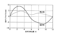
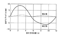
In this embodiment, the bending correction of the H-shaped steel in the above-described embodiment is performed for the H-shaped steel (nominal size H900 × 300 × 16 × 28, length 12 m) in which bending larger than the allowable value occurred during rolling. Corrected the bend according to the method. In this example, the number of correction sections was six, and the steepest descent method was used to determine the optimum length of each section length (conforming example). Further, in the comparative example, the correction was performed for the case where the six correction section lengths were fixed at equal intervals. The results of the distribution of bending per unit length before correction, the correction section, and the bending profile before and after correction are shown in FIG. 8 (comparative example) and FIG. 9 (example).
実施例及び比較例の両方の製品とも矯正前はS字曲がり形状であったが、実施例ではH形鋼を公差以下の曲がり量に矯正でき、合格となった。一方、比較例では矯正後も許容値以上の曲がりが残り、不合格となった。
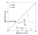
次に、同サイズのH形鋼について、実施例、比較例ともH形鋼10本ずつの曲がり矯正を行い、結果を比較した。これを図10に示す。図10において、横軸は矯正前の曲がり量であり、縦軸は矯正後の曲がり量である。また、「○」は実施例のデータであり、「□」は比較例のデータである。
図10に示すように、実施例では10本すべてで矯正後の曲がりが許容値以下となった。これに対し、比較例では10本中5本で矯正後の曲がりが許容値を超えており、これらの製品は不合格となった。
以上より、本発明の効果が明らかである。
Both products of the example and the comparative example had an S-curved shape before correction, but in the example, the H-shaped steel can be corrected to a bending amount less than the tolerance, and it passed. On the other hand, in the comparative example, even after the correction, the bend more than the allowable value remained and became a rejection.
Next, with respect to H-shaped steels of the same size, bending correction was performed on 10 H-shaped steels in each of the example and the comparative example, and the results were compared. This is shown in FIG. In FIG. 10, the horizontal axis is the amount of bending before correction, and the vertical axis is the amount of bending after correction. Moreover, "(circle)" is data of an Example, "(square)" is data of a comparative example.
As shown in FIG. 10, in all of the ten samples in the example, the post-correction bending became less than the allowable value. On the other hand, in the comparative example, the bending after correction exceeded the allowable value in 5 out of 10, and these products were rejected.
From the above, the effects of the present invention are clear.
なお、上述の実施形態及び実施例では、形鋼の長手方向の各位置での単位長さ当たりの曲がり量と、各区間での単位長さ当たりの曲がり量の平均値との誤差の総和が最小となるように、この各区間の長さがを決定する場合について説明した。しかしながら、区間長の計算は、必ずしも誤差が最小になる区間長を求める必要はない。誤差の許容値を例えば0.12mm/mに定めておき、区間長を変更していく計算の過程で、この誤差が許容値になれば、そのときの各区間長で矯正条件を決定するようにしてもよい。すなわち、H形鋼10の長手方向の各位置での単位長さ当たりの曲がり量と、各区間での単位長さ当たりの曲がり量の平均値との誤差の総和が予め設定した許容値以下となるように、この区間の長さを決定する。
この場合においても、曲がり矯正効果が発揮できる長さの許容値を予め定め、この予め定めた許容値以上となるように各区間の長さを決定することが好ましい。
In the above embodiments and examples, the sum of the errors between the amount of bending per unit length at each position in the longitudinal direction of the section steel and the average value of the amounts of bending per unit length in each section is The case where the length of each section is determined so as to be the minimum has been described. However, calculation of the section length does not necessarily have to determine the section length at which the error is minimized. For example, in the process of calculation in which the tolerance of the error is set to 0.12 mm / m and the section length is changed, if this error becomes the tolerance, the correction condition is determined by each section length at that time You may That is, the sum of errors between the amount of bending per unit length at each position in the longitudinal direction of H-
Also in this case, it is preferable to determine in advance the allowable value of the length at which the bend correction effect can be exhibited, and to determine the length of each section so as to be equal to or greater than the predetermined allowable value.
(他の実施形態)
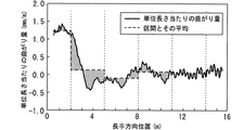
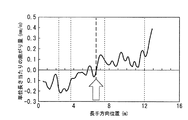
上述の一実施形態及び実施例では、形鋼の長手方向の各位置での単位長さ当たりの曲がり量と、各区間での単位長さ当たりの曲がり量の平均値との誤差の総和が最小となるように、この各区間の長さがを決定する場合について説明した。これをより簡易的に行う方法として、この実施形態のように、単位長さ当たりの曲がりの方向が変わる点を区間の区分点として設定する方法もある。例えば、図11のような単位長さ当たりの曲がり分布であれば、曲がりの方向が変わる長手6120mmの位置を区間の区分点(矢印で示す点)とする。そして、この区分点よりも前側を所定の数の矯正区間(図11の例では3つの区間)に分け、前側の3つの区間の区分については、図6と同様の方法で各区間の長さを決定する。そして、後側についても同様の方法で各区間長を設定する。この区間長の計算は、必ずしも誤差が最小になる区間長を求める必要はない。誤差の許容値を定めておき、区間長を変更していく計算の過程で、この誤差が許容値になれば、そのときの各区間長で矯正条件を決定してもよい。
(Other embodiments)
In the above-described one embodiment and example, the sum of the errors between the amount of bending per unit length at each position in the longitudinal direction of the section steel and the average value of the amounts of bending per unit length in each section is minimum As described above, the case where the length of each section is determined is described. As a method of performing this more simply, there is also a method of setting a point at which the bending direction per unit length changes as a section division point as in this embodiment. For example, in the case of a bending distribution per unit length as shown in FIG. 11, a position of 6120 mm in the longitudinal direction in which the bending direction changes is taken as a section dividing point (point indicated by an arrow). Then, the front side of this division point is divided into a predetermined number of correction sections (three sections in the example of FIG. 11), and the sections of the three sections on the front side are the lengths of the sections in the same manner as FIG. Decide. And each section length is set up by the same method also about the back side. In the calculation of the section length, it is not necessary to obtain the section length at which the error is minimized. In the process of calculation in which the tolerance of the error is determined and the section length is changed, if this error becomes the tolerance, the correction condition may be determined by each section length at that time.
以上、本発明を上記実施形態及び実施例に基づき具体的に説明したが、本発明は上記実施形態及び実施例に限定されるものではなく、その要旨を逸脱しない範囲において種々変更可能であることは勿論である。
例えば、本発明を適用できるH形鋼のサイズは特に限定されるものではなく、大型や小型など、あらゆるサイズのH形鋼に対して適用可能である。また、上述の本実施形態や実施例は圧延機(例えばユニバーサル圧延機)で成型されたH形鋼10の曲がりを矯正するものであるが、フランジとウェブとを溶接することでH断面形状とされる溶接H形鋼の曲がり矯正にも適用可能である。
As mentioned above, although this invention was concretely demonstrated based on the said embodiment and Example, this invention is not limited to the said embodiment and Example, A various change is possible in the range which does not deviate from the summary. Of course.
For example, the size of the H-section steel to which the present invention can be applied is not particularly limited, and the present invention can be applied to any size H-section steel such as large or small. In addition, although the above-described embodiment and examples correct the bending of the H-shaped
また、上述の実施形態及び実施例においては、H形鋼を例にして形鋼の曲がり矯正方法を説明したが、ウェブと該ウェブの高さ方向端部に設けられたフランジとを有する形鋼であれば、本発明を適用することが可能であり、例えばT形鋼にも適用可能である。ただし、T形鋼は、フランジがウェブの高さ方向一端にのみ設けられたものであり、本発明は曲がりの曲率半径方向内側のフランジを圧延することによりフランジを圧延させて曲がりを矯正するものであるため、T形鋼の場合には、フランジのある側が曲がりの曲率半径方向内側となる場合にのみ適用可能である。 In the above-described embodiments and examples, although the method of correcting bending of shaped steel has been described by taking H-shaped steel as an example, shaped steel having a web and a flange provided at the end in the height direction of the web Therefore, the present invention can be applied, for example, to T-shaped steel. However, T-shaped steel is provided with a flange only at one end in the height direction of the web, and the present invention is to correct the bend by rolling the flange by rolling the inside flange in the curvature radius direction of the bend. Therefore, in the case of T-section steel, it is applicable only when the side with a flange is inside the curvature radius of curvature.
1…H形鋼製造設備
1A…圧延成型設備
1B…曲がり矯正設備
2…曲がり測定装置
3A,3B…曲がり矯正機
4…演算処理装置
10…H形鋼
11…ウェブ
12…フランジ
21…支持ロール
22…矯正ロール
DESCRIPTION OF
Claims (5)
前記形鋼の長手方向に亘り、前記形鋼の前記ウェブ高さ方向の単位長さ当たりの曲がり形状曲線を得る曲がり形状測定工程と、
前記曲がり形状測定工程で得られた曲がり形状曲線に基づいて、前記フランジの圧延条件を決定する圧延条件決定工程と、
前記圧延条件決定工程により決定された圧延条件に従い、前記形鋼の長手方向に亘って前記フランジを圧延する圧延矯正工程とを備え、
前記圧延条件決定工程は、
前記形鋼の長手方向に複数の区間を設定し、前記各区間での前記形鋼の単位長さ当たりの曲がり量の平均値に基づき、前記フランジの圧延条件を決定するものであり、
前記各区間の長さについて、前記形鋼の長手方向の各位置での単位長さ当たりの曲がり量と、前記各区間での単位長さ当たりの曲がり量の平均値との誤差の総和が最小となるように前記各区間の長さを決定することを特徴とする形鋼の曲がり矯正方法。 A method of correcting bending in a web height direction of a shaped steel having a web and a flange provided at a height end of the web, the method comprising:
A bending shape measuring step of obtaining a bending shape curve per unit length in the web height direction of the section steel in the longitudinal direction of the section steel;
A rolling condition determination step of determining rolling conditions of the flange based on the curved shape curve obtained in the curved shape measurement step;
And a rolling correction step of rolling the flange in the longitudinal direction of the shaped steel in accordance with the rolling conditions determined by the rolling condition determination step,
The rolling condition determination process is
A plurality of sections are set in the longitudinal direction of the section steel, and the rolling condition of the flange is determined based on the average value of the bending amount per unit length of the section steel in each section.
The total sum of the errors between the amount of bending per unit length at each position in the longitudinal direction of the section and the average value of the amounts of bending per unit length for the length of each section is minimum A method of correcting bending of a shaped steel, comprising determining the length of each section to be
前記形鋼の長手方向に亘り、前記形鋼の前記ウェブ高さ方向の単位長さ当たりの曲がり形状曲線を得る曲がり形状測定工程と、
前記曲がり形状測定工程で得られた曲がり形状曲線に基づいて、前記フランジの圧延条件を決定する圧延条件決定工程と、
前記圧延条件決定工程により決定された圧延条件に従い、前記形鋼の長手方向に亘って前記フランジを圧延する圧延矯正工程とを備え、
前記圧延条件決定工程は、
前記形鋼の長手方向に複数の区間を設定し、前記各区間での前記形鋼の単位長さ当たりの曲がり量の平均値に基づき、前記フランジの圧延条件を決定するものであり、
前記各区間の長さについて、前記形鋼の長手方向の各位置での単位長さ当たりの曲がり量と、前記各区間での単位長さ当たりの曲がり量の平均値との誤差の総和が許容値以下となるように前記各区間の長さを決定することを特徴とする形鋼の曲がり矯正方法。 A method of correcting bending in a web height direction of a shaped steel having a web and a flange provided at a height end of the web, the method comprising:
A bending shape measuring step of obtaining a bending shape curve per unit length in the web height direction of the section steel in the longitudinal direction of the section steel;
A rolling condition determination step of determining rolling conditions of the flange based on the curved shape curve obtained in the curved shape measurement step;
And a rolling correction step of rolling the flange in the longitudinal direction of the shaped steel in accordance with the rolling conditions determined by the rolling condition determination step,
The rolling condition determination process is
A plurality of sections are set in the longitudinal direction of the section steel, and the rolling condition of the flange is determined based on the average value of the bending amount per unit length of the section steel in each section.
For the length of each section, the sum of the errors between the amount of bending per unit length at each position in the longitudinal direction of the section and the average value of the amounts of bending per unit length in each section is acceptable A method of correcting bending of a section steel, wherein the length of each section is determined so as to be equal to or less than a value.
Priority Applications (1)
| Application Number | Priority Date | Filing Date | Title |
|---|---|---|---|
| JP2017253533A JP7052352B2 (en) | 2017-12-28 | 2017-12-28 | Bending straightening method of shaped steel and manufacturing method of shaped steel |
Applications Claiming Priority (1)
| Application Number | Priority Date | Filing Date | Title |
|---|---|---|---|
| JP2017253533A JP7052352B2 (en) | 2017-12-28 | 2017-12-28 | Bending straightening method of shaped steel and manufacturing method of shaped steel |
Publications (2)
| Publication Number | Publication Date |
|---|---|
| JP2019118917A true JP2019118917A (en) | 2019-07-22 |
| JP7052352B2 JP7052352B2 (en) | 2022-04-12 |
Family
ID=67306770
Family Applications (1)
| Application Number | Title | Priority Date | Filing Date |
|---|---|---|---|
| JP2017253533A Active JP7052352B2 (en) | 2017-12-28 | 2017-12-28 | Bending straightening method of shaped steel and manufacturing method of shaped steel |
Country Status (1)
| Country | Link |
|---|---|
| JP (1) | JP7052352B2 (en) |
Citations (2)
| Publication number | Priority date | Publication date | Assignee | Title |
|---|---|---|---|---|
| JP2014140898A (en) * | 2012-12-27 | 2014-08-07 | Jfe Steel Corp | Bend straightening method for shape steel |
| JP2014208371A (en) * | 2013-03-27 | 2014-11-06 | Jfeスチール株式会社 | Method for correcting bend of shape steel |
-
2017
- 2017-12-28 JP JP2017253533A patent/JP7052352B2/en active Active
Patent Citations (2)
| Publication number | Priority date | Publication date | Assignee | Title |
|---|---|---|---|---|
| JP2014140898A (en) * | 2012-12-27 | 2014-08-07 | Jfe Steel Corp | Bend straightening method for shape steel |
| JP2014208371A (en) * | 2013-03-27 | 2014-11-06 | Jfeスチール株式会社 | Method for correcting bend of shape steel |
Also Published As
| Publication number | Publication date |
|---|---|
| JP7052352B2 (en) | 2022-04-12 |
Similar Documents
| Publication | Publication Date | Title |
|---|---|---|
| EP3922371B1 (en) | Method of cooling control for thick steel plate, cooling control device, and method of producing thick steel plate | |
| JP5967031B2 (en) | Method and apparatus for correcting the perpendicularity of H-shaped steel flange | |
| CN110366456B (en) | Cooling method of steel sheet, cooling device of steel sheet, and manufacturing method of steel sheet | |
| EP3888810B1 (en) | Method of controlling flatness of strip of rolled material, control system and production line | |
| JP6874794B2 (en) | Temper rolling method for hot-rolled steel sheet | |
| JP2016078057A (en) | Slab camber suppression method, camber suppression device, and slab guiding device | |
| JP7732145B2 (en) | METHOD FOR CONTROLLING THE WARPAGE OF METAL STRIP, METAL STRIP MANUFACTURING METHOD, AND METAL STRIP WARPAGE CONTROL DEVICE | |
| US10730087B2 (en) | Method for producing H-shaped steel and H-shaped steel product | |
| JP5867498B2 (en) | Bending correction method for shape steel | |
| JP4289480B2 (en) | Straightening method to obtain steel plate with good shape with little variation in residual stress | |
| JP7052352B2 (en) | Bending straightening method of shaped steel and manufacturing method of shaped steel | |
| WO2024105996A1 (en) | Method for predicting width of rough rolled material, method for controlling width of rough rolled material, method for producing hot-rolled steel sheet, and method for generating width prediction model for rough rolled material | |
| JP6569691B2 (en) | Manufacturing method of unequal side unequal thickness angle steel | |
| JP6743835B2 (en) | Method for rolling shaped steel and method for adjusting leveling amount in rolling shaped steel | |
| JP3211709B2 (en) | Manufacturing method of section steel | |
| JP3211710B2 (en) | Manufacturing method of section steel | |
| JP6477618B2 (en) | Method for rolling shape steel and rolling mill | |
| JP6172110B2 (en) | Hot rolled steel sheet rolling method | |
| JP7743845B2 (en) | Rolling method and rolling equipment for shapes | |
| JPH09216010A (en) | Manufacturing method of section steel | |
| JP4669376B2 (en) | Manufacturing method of thick steel plate with high flatness | |
| JP5407698B2 (en) | Manufacturing method and equipment for thick steel plate | |
| US11292039B2 (en) | Method for producing H-shaped steel | |
| JPH09174159A (en) | Manufacturing method of section steel | |
| WO2026048463A1 (en) | Shaped steel cold-rolled dimension prediction method, shaped steel manufacturing method, cold-rolled dimension prediction model generation method, and shaped steel cold-rolled dimension prediction device |
Legal Events
| Date | Code | Title | Description |
|---|---|---|---|
| A621 | Written request for application examination |
Free format text: JAPANESE INTERMEDIATE CODE: A621 Effective date: 20201119 |
|
| A977 | Report on retrieval |
Free format text: JAPANESE INTERMEDIATE CODE: A971007 Effective date: 20210831 |
|
| A131 | Notification of reasons for refusal |
Free format text: JAPANESE INTERMEDIATE CODE: A131 Effective date: 20210907 |
|
| A521 | Request for written amendment filed |
Free format text: JAPANESE INTERMEDIATE CODE: A523 Effective date: 20211105 |
|
| TRDD | Decision of grant or rejection written | ||
| A01 | Written decision to grant a patent or to grant a registration (utility model) |
Free format text: JAPANESE INTERMEDIATE CODE: A01 Effective date: 20220301 |
|
| A61 | First payment of annual fees (during grant procedure) |
Free format text: JAPANESE INTERMEDIATE CODE: A61 Effective date: 20220314 |
|
| R150 | Certificate of patent or registration of utility model |
Ref document number: 7052352 Country of ref document: JP Free format text: JAPANESE INTERMEDIATE CODE: R150 |
|
| R250 | Receipt of annual fees |
Free format text: JAPANESE INTERMEDIATE CODE: R250 |
|
| R250 | Receipt of annual fees |
Free format text: JAPANESE INTERMEDIATE CODE: R250 |