JP2019128331A - Temperature sensor and manufacturing method thereof - Google Patents
Temperature sensor and manufacturing method thereof Download PDFInfo
- Publication number
- JP2019128331A JP2019128331A JP2018011955A JP2018011955A JP2019128331A JP 2019128331 A JP2019128331 A JP 2019128331A JP 2018011955 A JP2018011955 A JP 2018011955A JP 2018011955 A JP2018011955 A JP 2018011955A JP 2019128331 A JP2019128331 A JP 2019128331A
- Authority
- JP
- Japan
- Prior art keywords
- sheath tube
- temperature
- temperature sensor
- end portion
- pair
- Prior art date
- Legal status (The legal status is an assumption and is not a legal conclusion. Google has not performed a legal analysis and makes no representation as to the accuracy of the status listed.)
- Granted
Links
Images








Landscapes
- Measuring Temperature Or Quantity Of Heat (AREA)
Abstract
【課題】非接地型の温度センサの応答性を改善することができる温度センサ及びその製造方法を提供する。【解決手段】温度センサ1は、一対の熱電対素線2、一対の熱電対素線2の先端同士が接合された測温接点3、測温接点3を先端部401内に収容するシース管4、シース管4の先端部401に装着された先端カバー42、一対の熱電対素線2とシース管4とを絶縁する絶縁材5、及びシース管4の基端部402内に充填されたガラス封止材6を備える。先端カバー42内であって絶縁材5の先端側X1に隣接する位置には、測温接点3が収容されるとともに、密度が0.9kg/m3以下の空気による気相Kが形成されている。【選択図】図1PROBLEM TO BE SOLVED: To provide a temperature sensor capable of improving the responsiveness of a non-grounded temperature sensor and a method for manufacturing the same. SOLUTION: A temperature sensor 1 has a pair of thermocouple strands 2, a temperature measuring contact 3 in which the tips of the pair of thermocouple strands 2 are joined to each other, and a sheath tube for accommodating the temperature measuring contact 3 in a tip portion 401. 4. The tip cover 42 attached to the tip 401 of the sheath tube 4, the insulating material 5 that insulates the pair of thermocouple strands 2 from the sheath tube 4, and the base end 402 of the sheath tube 4 are filled. A glass encapsulant 6 is provided. A temperature measuring contact 3 is housed in the tip cover 42 and adjacent to the tip side X1 of the insulating material 5, and a gas phase K with air having a density of 0.9 kg / m3 or less is formed. .. [Selection diagram] Fig. 1
Description
本発明は、測定環境下の測定対象ガスの温度を測定する温度センサ及びその製造方法に関する。 The present invention relates to a temperature sensor that measures the temperature of a gas to be measured under a measurement environment and a method of manufacturing the same.
一対の熱電対素線を有する熱電対式の温度センサは、例えば、車両の排気管内を流れる排ガスの温度を測定するために用いられる。一対の熱電対素線は、酸化マグネシウム、酸化アルミニウム等の絶縁材によって、絶縁された状態でシース管内に固定されている。また、シース管の先端部は金属材料によって閉塞されており、シース管の基端部はガラス、樹脂等の封止材によって閉塞されている。そして、シース管内を外部から遮断することにより、一対の熱電対素線を酸化による特性劣化から保護するとともに、絶縁材を吸湿による絶縁不良から保護している。 A thermocouple-type temperature sensor having a pair of thermocouple wires is used, for example, to measure the temperature of exhaust gas flowing in the exhaust pipe of a vehicle. The pair of thermocouple wires are fixed in the sheath tube in a state of being insulated by an insulating material such as magnesium oxide or aluminum oxide. Further, the distal end of the sheath tube is closed by a metal material, and the proximal end of the sheath tube is closed by a sealing material such as glass or resin. Then, by shielding the inside of the sheath tube from the outside, the pair of thermocouple strands are protected from characteristic deterioration due to oxidation, and the insulating material is protected from insulation failure due to moisture absorption.
熱電対式の温度センサには、測温接点がシース管の先端部に接地された接地型のもの、測温接点がシース管の先端部に接地されていない非接地型のもの等がある。主に応答性が求められる場合には、接地型のものが用いられ、主に耐ノイズ性が求められる場合には、非接地型のものが用いられる。 The thermocouple type temperature sensor includes a grounding type in which the temperature measuring contact is grounded to the distal end portion of the sheath tube, and a non-grounded type in which the temperature measuring contact is not grounded to the distal end portion of the sheath tube. When responsiveness is mainly required, a grounded type is used, and when noise resistance is mainly required, a non-grounded type is used.
また、熱電対式の温度センサに関するものではないが、例えば、特許文献1の白金測温抵抗素子においては、アルミナ保護管内に白金センサが配置された非接地型の温度センサについて記載されている。この白金測温抵抗素子においては、アルミナ保護管内の空気を乾燥状態にすることが記載されている。
Although not related to a thermocouple type temperature sensor, for example, in the platinum resistance thermometer element of
測温接点の周りがフィラー等によって充填されていない非接地型の温度センサは、フィラーとシース管との線膨張係数の差に起因する熱ストレスの影響を受けない点で有利である。しかし、非接地型の温度センサは、測温接点がシース管に接地されていないために、測温接点の温度が測定対象ガスの温度になるまでに時間が掛かり、温度センサの応答性に優れない点で不利である。 An ungrounded temperature sensor in which the temperature measuring contact is not filled with a filler or the like is advantageous in that it is not affected by thermal stress due to the difference in linear expansion coefficient between the filler and the sheath tube. However, since the temperature measuring contact is not grounded to the sheath tube in the non-grounding type temperature sensor, it takes time until the temperature of the temperature measuring contact reaches the temperature of the gas to be measured, and the temperature sensor has excellent responsiveness. It is disadvantageous in that it is not.
一般的に、温度センサの応答性を重視する場合には、測温接点がシース管に接地された接地型の温度センサが用いられる。一方、特に車載用の温度センサにおいては、熱ストレスに起因する耐久性、耐ノイズ性を重視するため、非接地型の温度センサを用いたいという要望がある。この場合、非接地型の温度センサの応答性を如何にして改善するかが課題となる。 In general, when importance is attached to the responsiveness of the temperature sensor, a grounded temperature sensor in which the temperature measurement contact is grounded to the sheath tube is used. On the other hand, there is a demand to use a non-grounded temperature sensor in order to emphasize durability and noise resistance caused by thermal stress, particularly in a vehicle-mounted temperature sensor. In this case, the problem is how to improve the response of the non-grounded temperature sensor.
なお、特許文献1の白金測温抵抗素子においては、白金センサがアルミナ保護管内に、封止材及び高温用セメントによって封入された後に、さらにアルミナ保護管内の空気を乾燥させている。つまり、アルミナ保護管内が完全には封止されていないことにより、アルミナ保護管内の空気を乾燥させることが可能となる。特許文献1の白金測温抵抗素子においても、非接地型の温度センサの応答性を改善する工夫はなされていない。
In the platinum resistance temperature detector of
本発明は、かかる課題に鑑みてなされたもので、測温接点の周りがフィラー等によって充填されていない非接地型の温度センサの応答性を改善することができる温度センサ及びその製造方法を提供しようとして得られたものである。 The present invention has been made in view of such a problem, and provides a temperature sensor capable of improving the responsiveness of a non-grounding type temperature sensor in which the temperature measuring contact is not filled with a filler or the like, and a method for manufacturing the same. It was obtained by trying.
本発明の一態様は、互いに異なる金属材料から構成された一対の熱電対素線(2)と、
一対の前記熱電対素線の先端同士が合わさった測温接点(3)と、
金属材料から構成され、前記測温接点を先端部(401)内又は前記先端部に装着された先端カバー(42)内に収容するとともに、一対の前記熱電対素線を基端部(402)から突出させるシース管(4)と、
絶縁材料から構成され、前記シース管内に配置されるとともに、一対の前記熱電対素線と前記シース管とを絶縁して、一対の前記熱電対素線を前記シース管に固定する絶縁材(5)と、
前記シース管の前記基端部内及び前記シース管の前記基端部に装着されたホルダ(43)内の少なくとも一方に充填されるとともに、前記シース管内を封止する封止材(6)と、を備え、
前記シース管の前記先端部内及び前記先端カバー内の少なくとも一方であって前記絶縁材の先端側に隣接する位置には、前記測温接点が収容されるとともに、密度が0.9kg/m3以下の気相(K)が形成されている、温度センサ(1)にある。
One aspect of the present invention is a pair of thermocouple wires (2) made of different metal materials,
A temperature measurement contact (3) in which the tips of the pair of thermocouple wires are combined;
The temperature measuring contact is made of a metal material, and the temperature measurement contact is accommodated in the distal end portion (401) or in the distal end cover (42) attached to the distal end portion, and a pair of the thermocouple wires at the proximal end (402) A sheath tube (4) projecting from
An insulating material (5), which is made of an insulating material, is disposed in the sheath tube, and insulates the pair of thermocouple wires from the sheath tube to fix the pair of thermocouple wires to the sheath tube. )When,
A sealing material (6) filled in at least one of the proximal end portion of the sheath tube and a holder (43) attached to the proximal end portion of the sheath tube, and sealing the sheath tube; Equipped with
The temperature measuring contact is accommodated at a position adjacent to the distal end side of the insulating material in at least one of the distal end portion and the distal end cover of the sheath tube, and the density is 0.9 kg / m 3 or less. Is in the temperature sensor (1) where the gas phase (K) is formed.
本発明の他の態様は、互いに異なる金属材料から構成された一対の熱電対素線(2)と、
一対の前記熱電対素線の先端同士が合わさった測温接点(3)と、
金属材料から構成され、前記測温接点を先端部(401)内又は前記先端部に装着された先端カバー(42)内に収容するとともに、一対の前記熱電対素線を基端部(402)から突出させるシース管(4)と、
絶縁材料から構成され、前記シース管内に配置されるとともに、一対の前記熱電対素線と前記シース管とを絶縁して、一対の前記熱電対素線を前記シース管に固定する絶縁材(5)と、
前記シース管の前記基端部内及び前記シース管の前記基端部に装着されたホルダ(43)内の少なくとも一方に充填されるとともに、前記シース管内を封止する封止材(6)と、を備え、
前記シース管の前記先端部内及び前記先端カバー内の少なくとも一方であって前記絶縁材の先端側に隣接する位置に、前記測温接点が収容された気相(K)が形成された温度センサ(1)の製造方法において、
前記気相(K)が形成されたセンサ中間体(13)を加熱した状態において、前記封止材を、前記シース管の前記基端部内及び前記ホルダ内の少なくとも一方に充填して、前記シース管内を封止するとともに、前記気相の密度を0.9kg/m3以下にする、温度センサの製造方法にある。
Another aspect of the present invention is a pair of thermocouple wires (2) made of different metal materials;
A temperature measurement contact (3) in which the tips of the pair of thermocouple wires are combined;
It is made of a metal material, and the temperature measuring contact is accommodated in the distal end portion (401) or the distal end cover (42) attached to the distal end portion, and the pair of thermocouple wires is proximal end portion (402). A sheath tube (4) projecting from
An insulating material (5) which is made of an insulating material, is disposed in the sheath tube, insulates the pair of thermocouple wires from the sheath tube, and fixes the pair of thermocouple wires to the sheath tube. )When,
A sealing material (6) for filling at least one of the inside of the sheath tube and the holder (43) attached to the proximal end of the sheath tube, and sealing the inside of the sheath tube; With
A temperature sensor in which a gas phase (K) containing the temperature measuring contact is formed at a position adjacent to the distal end side of the insulating material in at least one of the distal end portion and the distal end cover of the sheath tube ( In the manufacturing method of 1),
In a state where the sensor intermediate (13) in which the gas phase (K) is formed is heated, the sealing material is filled in at least one of the proximal end portion and the holder of the sheath tube, and the sheath A method of manufacturing a temperature sensor, which seals the inside of a tube and makes the density of the gas phase 0.9 kg / m 3 or less.
前記一態様の温度センサにおいては、非接地型である熱電対式の温度センサの応答性を改善する工夫をしている。そして、本願の発明者は、シース管の先端部内及び先端カバー内の少なくとも一方に形成された気相の密度の違いが、温度センサの応答性に影響していることを見出した。 In the temperature sensor of the one aspect, the responsiveness of the non-grounded thermocouple type temperature sensor is improved. And the inventor of this application discovered that the difference in the density of the gaseous phase formed in at least one in the front-end | tip part of a sheath pipe | tube and a front-end | tip cover has influenced the responsiveness of the temperature sensor.
一般的に、接地型の温度センサの応答性が非接地型の温度センサの応答性よりも優れる性質は、接地型の温度センサにおける測温接点とシース管との間の熱伝導率が、非接地型の温度センサにおける測温接点とシース管との間の熱伝導率よりも高いことによって説明することができる。一方、非接地型の温度センサの応答性の良し悪しは、熱拡散率として、測定対象ガスと測温接点との間での温度の伝わりやすさによって説明することができる。 In general, grounded temperature sensors are more responsive than non-grounded temperature sensors because the thermal conductivity between the temperature measuring contact and the sheath tube in the grounded temperature sensor is non- This can be explained by the fact that the thermal conductivity between the temperature measuring contact and the sheath tube in the grounded temperature sensor is higher. On the other hand, the responsiveness of the non-grounded temperature sensor can be explained by the ease of temperature transfer between the measurement target gas and the temperature measuring contact as the thermal diffusivity.
この熱拡散率α[m2/s]は、熱伝導率をk[W/(m・K)]、比熱をc[J/(kg・K)]、密度をρ[kg/m3]としたとき、α=k/(c・ρ)によって表される。つまり、温度センサの応答性は、熱伝導率が高いほど高くなる一方、比熱又は密度が高いほど低くなる性質を有する。そして、前記一態様の温度センサにおいては、密度を低くすることによって熱拡散率を高くし、非接地型の温度センサの応答性を改善している。 This thermal diffusivity α [m 2 / s] has a thermal conductivity of k [W / (m · K)], a specific heat of c [J / (kg · K)], and a density of ρ [kg / m 3 ]. Is expressed by α = k / (c · ρ). That is, the responsiveness of the temperature sensor is higher as the thermal conductivity is higher, but lower as the specific heat or density is higher. And in the temperature sensor of the said one aspect, the thermal diffusivity is made high by lowering the density, and the responsiveness of the non-grounded temperature sensor is improved.
より具体的には、前記一態様の温度センサにおいては、シース管の先端部内及び先端カバー内の少なくとも一方であって絶縁材の先端側に隣接する位置に形成された気相の密度を、0.9kg/m3以下としている。これにより、温度センサの熱拡散率を高くすることができ、非接地型の温度センサの応答性を改善することができる。なお、従来の非接地型の温度センサの気相の密度は、常温における空気の密度として、1.2kg/m3程度であると考える。 More specifically, in the temperature sensor of the one aspect, the density of the gas phase formed at a position adjacent to the distal end side of the insulating material in at least one of the distal end portion and the distal end cover of the sheath tube is set to 0. .9 kg / m 3 or less. Thereby, the thermal diffusivity of the temperature sensor can be increased, and the responsiveness of the non-grounded temperature sensor can be improved. The density of the gas phase of the conventional non-grounded type temperature sensor is considered to be about 1.2 kg / m 3 as the density of air at normal temperature.
それ故、前記一態様の温度センサによれば、測温接点の周りがフィラー等によって充填されていない非接地型の温度センサの応答性を改善することができる。 Therefore, according to the temperature sensor of the one aspect, it is possible to improve the responsiveness of the non-grounded temperature sensor in which the surroundings of the temperature measurement contact are not filled with the filler or the like.
前記他の態様の温度センサの製造方法は、応答性が改善された非接地型の温度センサの製造に適したものである。具体的には、センサ中間体を加熱した状態において、封止材を、センサ中間体におけるシース管の基端部内に充填して、シース管内を封止する。これにより、シース管内の気相の密度を0.9kg/m3以下にすることができる。 The manufacturing method of the temperature sensor according to the other aspect is suitable for manufacturing a non-grounded temperature sensor whose response is improved. Specifically, in a state where the sensor intermediate is heated, the sealing material is filled in the proximal end of the sheath tube in the sensor intermediate to seal the inside of the sheath tube. Thereby, the density of the gas phase in the sheath tube can be reduced to 0.9 kg / m 3 or less.
それ故、前記他の態様の温度センサの製造方法によれば、応答性が改善された非接地型の温度センサを容易に製造することができる。 Therefore, according to the method of manufacturing the temperature sensor of the other aspect, it is possible to easily manufacture a non-grounded temperature sensor with improved responsiveness.
なお、本発明の一態様及び他の態様において示す各構成要素のカッコ書きの符号は、実施形態における図中の符号との対応関係を示すが、各構成要素を実施形態の内容のみに限定するものではない。 In addition, although the code | symbol of the parentheses of each component shown in 1 aspect of this invention and another aspect shows the correspondence with the code | symbol in the figure in embodiment, each component is limited only to the content of embodiment. It is not a thing.
前述した温度センサ及びその製造方法にかかる好ましい実施形態について、図面を参照して説明する。
<実施形態>
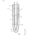
本形態の温度センサ1は、図1及び図2に示すように、一対の熱電対素線2、測温接点3、シース管4、先端カバー42、絶縁材5及びガラス封止材6を備える。一対の熱電対素線2のそれぞれは、互いに異なる金属材料から構成されている。測温接点3は、一対の熱電対素線2の先端同士が接合されたものである。シース管4は、金属材料から構成されており、測温接点3を先端部401に装着された先端カバー42内に収容するとともに、一対の熱電対素線2を基端部402から突出させている。先端カバー42は、シース管4の先端外周部に装着されており、シース管4の先端側X1を閉塞している。
A preferred embodiment of the above-described temperature sensor and a method of manufacturing the same will be described with reference to the drawings.
Embodiment
As shown in FIGS. 1 and 2, the
絶縁材5は、絶縁材料から構成されており、シース管4内に配置されるとともに、一対の熱電対素線2とシース管4とを絶縁して、一対の熱電対素線2をシース管4に固定している。ガラス封止材6は、ガラス材料から構成されており、シース管4の基端部402内に充填されるとともに、シース管4内を封止している。先端カバー42内であって絶縁材5の先端側X1に隣接する位置には、測温接点3が収容されるとともに、密度が0.9kg/m3以下の空気による気相Kが形成されている。
The insulating
図1及び図2に示すように、本形態の温度センサ1において、先端側X1とは、シース管4の中心軸線に沿った軸方向Xにおいて、シース管4に対して測温接点3が設けられた側のことをいう。基端側X2とは、軸方向Xにおける先端側X1とは反対側のことをいう。
As shown in FIGS. 1 and 2, in the
以下に、本形態の温度センサ1及びその製造方法について詳説する。
(温度センサ1)
図2に示すように、温度センサ1は、車載用のものであり、自動車における内燃機関(エンジン)の吸気管内又は排気管内を流れる流体の温度を測定するために使用される。本形態の温度センサ1は、排気管15に配置され、排気管15内を流れる、測定環境下の測定対象ガスGとしての排ガスの温度を測定するために用いられる。排ガスの温度は、制御装置(電子制御ユニット)100によって内燃機関の燃焼制御を行う際に利用される。また、排ガスの温度は、例えば、排気管に配置された排気浄化触媒の温度を検知するために利用することができる。また、温度センサ1は、例えば、排気管内の排ガスを吸気管へ再循環させる排気再循環経路の吸気管に配置することもできる。
Below, the
(Temperature sensor 1)
As shown in FIG. 2, the
図13に示すように、本形態の一対の熱電対素線2、シース管4及び絶縁材5は、シースピン12として一体的に成形されたものを利用したものである。温度センサ1の主要部は、一対の熱電対素線2、測温接点3、シース管4、絶縁材5及びガラス封止材6によってシース熱電対11として形成される。図3には、シース熱電対11及びシースピン12の軸方向Xに直交する断面を示す。
As shown in FIG. 13, the pair of
図2に示すように、温度センサ1は、シース熱電対11を内周側に保持する第1ハウジング71と、第1ハウジング71に接合された第2ハウジング72と、第1ハウジング71及び第2ハウジング72に取り付けられた基端側カバー73と、基端側カバー73内に保持された保持材74及びブッシュ75とを更に備える。保持材74は、一対の熱電対素線2に接続された端子金具76を保持し、ブッシュ75は、端子金具76に接続されたリード線77を保持する。なお、ブッシュ75によって一対の熱電対素線2に接続された端子金具76を保持することによって、保持材74を廃止することもできる。熱電対素線2とリード線77との接続構造は、適宜変更することができる。
As shown in FIG. 2, the
(シース管4)
シース管4は、金属シースとも呼ばれ、ステンレス(SUS、NCA)、Ni基耐熱合金(NCF)等の金属材料によって構成されている。図13に示すように、シース管4は、円筒形状を有するシースピン12の外管を利用したものである。シース管4の先端部401は、金属材料によって閉塞されている。本形態のシース管4の先端部401は、図1に示すように、円筒部41の先端部401の外周に装着された先端カバー42によって閉塞されている。シース管4の先端部401は、図4に示すように、円筒部41の先端部401から連続して設けられた蓋部42Aによって閉塞されていてもよい。蓋部42Aは、シース管4の円筒部41の先端に溶接された金属片によって構成することができる。
(Sheath tube 4)
The
図1に示すように、本形態のシース管4は、円筒形状を有する円筒部41と、円筒部41の先端外周部に装着された先端カバー42とを有する。先端カバー42は、円筒部41の先端外周部に溶接によって接合されている。先端カバー42は、円筒部41の先端外周部に装着されたカバー基端部421の内径に対して、カバー基端部421よりも先端側X1に位置するカバー先端部422の内径が小さくなっている。カバー先端部422の先端位置には、曲面状の底部が形成されている。先端カバー42のカバー先端部422の軸方向Xの長さ、絞り段数、底部形状等は、適宜変更することができる。
As shown in FIG. 1, the
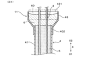
図5に示すように、シース管4の基端部402には、ガラス封止材6用のタブレット60を配置するためのホルダ43を装着することができる。ホルダ43は、漏斗形状を有し、シース管4の外径よりも大きな内径の上方開口部431を有している。ホルダ43は、タブレット60が溶融したガラス材料を、シース管4の基端部402内へ充填するために用いられる。ホルダ43は、シース管4の基端部402の外周に圧入させることができ、シース管4の基端部402の外周にかしめ固定又は溶接することもできる。
As shown in FIG. 5, a
ホルダ43内に配置するタブレット60のサイズは、シース管4の基端部402内に配置する場合よりも大きくすることができる。そして、ホルダ43内に配置されたタブレット60がガラス材料として溶融したときには、このガラス材料は、ホルダ43内からシース管4の基端部402内へ流れ込むことができる。これにより、多くのガラス材料を溶融させることができ、シース管4の基端部402内へ十分なガラス材料を供給することができる。そのため、ガラス封止材6によってシース管4内を、より効果的に封止することができる。
The size of the
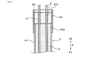
また、図6に示すように、ホルダ43を用いる場合には、ガラス封止材6はホルダ43内に充填して、シース管4の基端部402を封止することもできる。この場合には、シースピン12の基端部(シース管4の基端部402)から絶縁材5を掻き出す手間を省くことができる。また、図7に示すように、ホルダ43の形状は、漏斗形状とする以外にも、円筒形状等としてもよい。
As shown in FIG. 6, when the
(一対の熱電対素線2)
一対の測温接点3は、いわゆるゼーベック効果を生じさせるために、互いに異なる金属材料によって構成されている。本形態の一対の熱電対素線2は、Nタイプの熱電対(シース熱電対11)を構成するものである。この構成により、温度センサ1による測温範囲を高くすることが容易である。本形態の温度センサ1は、1000℃以上の高温の測定対象ガスGの温度を測定可能である。熱電対素線2の+脚は、Ni(ニッケル)、Cr(クロム)、Si(シリコン)を主成分とする合金であるナイクロシルからなる。熱電対素線2の−脚は、Ni(ニッケル)、Si(シリコン)を主成分とする合金であるナイシルからなる。
(A pair of thermocouple wires 2)
The pair of
なお、一対の熱電対素線2は、Nタイプ以外にも、種々のタイプの熱電対を構成するものとしてもよい。例えば、一対の熱電対素線2は、+脚がNi及びCrを主成分とするクロメルからなり、−脚がNiを主成分とするアルメルからなるKタイプの熱電対を構成するものとしてもよい。
The pair of
図2に示すように、一対の熱電対素線2は、シース管4内において互いに平行な状態で挿通されている。一対の熱電対素線2は、シース管4から基端側X2に引き出されており、温度センサ1に設けられた端子金具76及びリード線77を介して、外部の制御装置100に接続される。制御装置100は、エンジン制御ユニット(ECU)に接続されたセンサ制御ユニット(SCU)とすることができる。また、制御装置100は、エンジン制御ユニットに構築することもできる。
As shown in FIG. 2, the pair of
(測温接点3)
図2に示すように、測温接点3は、熱接点とも呼ばれ、一対の熱電対素線2の+脚を構成する金属材料と、−脚を構成する金属材料とが融合して玉状に形成されたものである。測温接点3及び測温接点3の周辺に位置する先端カバー42等によって、温度センサ1の測温先端部10が形成される。温度センサ1の一対の熱電対素線2が端子金具76、リード線77等を介して制御装置100内のアンプに接続されることにより、温度を測定するための回路が形成される。一対の熱電対素線2における、測温接点3とは反対側に位置する基準接点は、制御装置100内に形成されている。測温接点3と基準接点との温度差が、一対の熱電対素線2に起電力を生じさせる。
(Temperature contact 3)
As shown in FIG. 2, the
図1に示すように、本形態の測温接点3は、シース管4の先端部401に装着された先端カバー42内の気相K中に配置されている。一対の熱電対素線2の先端部201及び測温接点3は、シース管4の円筒部41の先端開口部411から先端側X1に突出した位置に配置されている。
As shown in FIG. 1, the
測温接点3は、できるだけ球形状に近い形状に形成することが好ましい。ただし、測温接点3を真球形状に形成することは難しい。測温接点3は、略球形状の他、扁平した球形状、潰れた球形状、長球形状、楕円体等の種々の形状を有していてもよい。
It is preferable that the
(気相K)
本形態の気相Kの密度、及びシース管4内に存在する気体の密度は、0.26〜0.9kg/m3の範囲内にある。本形態の気相K及びシース管4内の気体は、空気によって構成されている。なお、気相Kを構成する気体及びシース管4内の気体は、空気以外の気体、例えば、窒素等とすることもできる。
(Gas phase K)
The density of the gas phase K in this embodiment and the density of the gas present in the
図8には、温度が変化したときの空気の密度を示す。この空気の密度は、標準気圧(1atm)における密度として示す。温度が高くなるにつれて、空気の密度は温度に反比例するように低下する。空気の密度は、その温度が約120℃にあるときに0.9kg/m3となる。本形態のシース管4の先端部401における気相Kは、温度センサ1の製造時において、シース管4内の空気の温度が120℃以上であるときに、ガラス封止材6によってシース管4内を封止することによって形成されたものである。
FIG. 8 shows the density of air when the temperature changes. The density of this air is shown as the density at standard atmospheric pressure (1 atm). As the temperature increases, the density of air decreases in inverse proportion to the temperature. The density of air is 0.9 kg / m 3 when its temperature is about 120 ° C. The vapor phase K at the
空気の温度が1050〜1100℃であるときには、その密度が0.26kg/m3となる。シース管4内の空気を加熱することができる温度は、シース管4及び先端カバー42を構成する金属材料の融点以下となる。シース管4及び先端カバー42を構成する金属材料の一つであるスーパーステンレス(NCF601)の融点は、1360〜1411℃程度である。よって、気相Kの密度を、0.26kg/m3未満にすることは困難である。
When the temperature of the air is 1050 to 1100 ° C., the density is 0.26 kg / m 3 . The temperature at which the air in the
また、シース管4内の空気を加熱する温度は、例えば500〜800℃に設定することができる。そして、気相Kの密度は、例えば、0.33〜0.46kg/m3の範囲内に設定することができる。
Moreover, the temperature which heats the air in the sheath pipe |
シース管4内に存在する空気は、気相Kを形成する空気の他に、絶縁材5を構成する金属酸化物の粉末間の空隙として存在する空気もある。そして、気相Kと絶縁材5内の空隙とは連通しており、気相Kの密度は、シース管4内の空気の密度と同じである。
The air present in the
(気相K及びシース管4内の密度の測定方法)
気相Kを構成する空気の密度及びシース管4内の空気の密度は、例えば、次のように測定することができる。すなわち、気体の密度をρ(kg/m3)、気体の圧力をP(hPa)、気体の温度をT(℃)、気体定数をRとしたとき、P=ρ・R・Tの関係が成り立つ。従って、温度Tを一定にして、大気圧P0とシース管4内の空気の圧力P1との差を図り、大気圧P0に比べてシース管4内の空気の圧力P1がどれだけ低いかに基づいて、大気の密度ρ0よりもシース管4内の空気の密度ρ1がどれだけ低いかを知ることができる。
(Measurement method of gas phase K and density in sheath tube 4)
The density of the air constituting the gas phase K and the density of the air in the
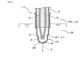
シース管4内の空気の密度は、より具体的には、次のように測定することができる。例えば、図9に示すように、液体Wの表面に加わる圧力を大気圧P0とし、温度センサ1のシース熱電対11の測温先端部10を液体中に配置する。この状態で先端カバー42に工具T等によって貫通孔Hを明ける。このとき、シース管4内の空気の圧力P1が大気圧P0よりも低い場合には、シース管4内へ液体Wが入る。次いで、貫通孔Hに蓋をした状態で液体W中からシース熱電対11の測温先端部10を取り出す。
More specifically, the density of air in the
次いで、シース管4内へ入った液体Wの量を、気圧差液体量として測定する。一方、シース管4内の液体Wを排出した後、貫通孔Hからシース管4内へ、液体Wを、シース管4内の隙間が満水になるまで注入する。その後、シース管4内の液体Wを排出し、排出される液体Wの量を、全体液体量として測定する。そして、全体液体量に対する気圧差液体量の割合に基づいて、大気の密度ρ0よりもシース管4内の空気の密度ρ1がどれだけ低いかを推定することができる。
Next, the amount of liquid W entering the
なお、一連の作業は、大気及び液体Wの温度Tがほぼ一定の状態で行う。また、全体液体量に対する気圧差液体量の割合と、シース管4内の空気の密度ρ1との関係を、関係マップとして作成しておくことにより、シース管4内の空気の密度ρ1の推定を容易にすることができる。
In addition, a series of operation | work is performed in the state where temperature T of air | atmosphere and the liquid W is substantially constant. In addition, the relationship between the ratio of the pressure difference liquid amount with respect to the total liquid amount and the air density ρ1 in the
(絶縁材5)
図1に示すように、絶縁材5は、酸化マグネシウム(MgO)、酸化アルミニウム(Al2O3)等の金属酸化物の粉末によって構成されている。シース管4の内周と一対の熱電対素線2の外周との隙間には、絶縁材5の粉末が充填されている。絶縁材5の粉末同士の間には、空隙が形成されている。絶縁材5の粉末は、シースピン12の直径を小さくする成形が行われる際に圧縮されている。そして、絶縁材5の粉末によって、一対の熱電対素線2がシース管4内に保持されている。
(Insulating material 5)
As shown in FIG. 1, the insulating
(ガラス封止材6)
シース管4の基端部402内には、シース管4内を封止して外部と遮断するためのガラス封止材6が充填されている。そして、シース管4内の測温接点3、一対の熱電対素線2及び絶縁材5には、外部の測定対象ガスG等が接触しないようになっており、シース管4内へ酸素、水分等が入らないようにしている。
(Glass sealing material 6)
The
ガラス封止材6は、Bi(ビスマス)を含有するBi系ガラス、又はPb(鉛)を含有するPb系ガラスによって構成されている。Bi系ガラスは、Bi2O3(酸化ビスマス)を主成分とし、他の酸化物等を含有するものである。他の酸化物には、B2O3、SrO、ZnO、BaO等がある。Pb系ガラスは、PbO(酸化鉛)を主成分とし、他の酸化物等を含有するものである。他の酸化物には、B2O3、SrO、ZnO、SiO2等がある。
The
ガラス封止材6は、固形状に形成されたガラスのタブレット60を用い、このタブレット60を溶融させた後に固化させて形成されたものである。図10に示すように、タブレット60は、シース管4の基端部402の内周又はホルダ43の内周に挿入できる大きさを有する。また、タブレット60は、一対の熱電対素線2を挿通させることができる2つの挿通穴601を有する。なお、ガラス封止材6は、固形状に形成されたタブレットではなく、粉末ガラスを用いて形成することもできる。
The
なお、ガラス材料によるガラス封止材の代わりに、樹脂材料による樹脂封止材を用いることもできる。ただし、この場合には、樹脂材料の耐熱性を十分に考慮する必要がある。 In addition, instead of the glass sealing material by a glass material, the resin sealing material by a resin material can also be used. However, in this case, it is necessary to fully consider the heat resistance of the resin material.
(加熱装置8)
図11及び図12に示すように、本形態の温度センサ1のシース熱電対11を製造する際には、シース管4の先端部401及び基端部402を加熱するための加熱装置8を用いる。加熱装置8は、シース管4の先端部401を加熱する温度と、シース管4の基端部402を加熱する温度とを別々に制御することができる構造を有する。加熱装置8は、電気式、燃焼式等の種々の加熱方式によって加熱するものとすることができる。
(Heating device 8)
As shown in FIGS. 11 and 12, when manufacturing the
加熱装置8は、例えば、一対の熱電対素線2、測温接点3、シース管4、先端カバー42及び絶縁材5が組み付けられたシース熱電対11の中間体であるセンサ中間体13を配置するための加熱炉81と、通電によって加熱炉81内を加熱する電気式のヒータ82A,82Bとを備えるものとすることができる。なお、図11及び図12においては、シース管4の基端部402内にガラス封止材6が形成された状態を示す。
The
ヒータ82A,82Bは、通電することによって発熱する発熱体を用いたものとすることができる。ヒータ82A,82Bは、シース管4の先端部401の周辺を加熱する第1ヒータ82Aと、シース管4の基端部402の周辺を加熱する第2ヒータ82Bとから構成することができる。第1ヒータ82A及び第2ヒータ82Bは、ヒータ制御装置83によって別々に通電可能である。
The
ヒータ制御装置83は、第1ヒータ82Aへの印加電力、通電時間等、及び第2ヒータ82Bへの印加電力、通電時間等を別々に設定可能である。そして、ヒータ制御装置83は、第1ヒータ82Aへの通電によって加熱炉81内の雰囲気ガスを加熱する温度と、第2ヒータ82Bへの通電によって加熱炉81内の雰囲気ガスを加熱する温度とを別々に制御することができる。
The
また、加熱炉81は、図11に示すように、センサ中間体13の全体を配置可能な1つの加熱炉81とすることができる。この場合には、加熱炉81の構成を簡単にすることができる。また、加熱炉81は、図12に示すように、センサ中間体13におけるシース管4の先端部401を配置可能な第1加熱炉81Aと、センサ中間体13におけるシース管4の基端部402を配置可能な第2加熱炉81Bとから構成することもできる。この場合には、第1ヒータ82Aによって加熱する雰囲気ガスの温度と、第2ヒータ82Bによって加熱する雰囲気ガスの温度とを、より適切に制御することができる。
Moreover, the
なお、センサ中間体13を加熱する際には、加熱炉81を用いないこともできる。この場合にも、シース管4の先端部401の温度及び基端部402の温度が目標とする温度になるよう、各ヒータ82A,82Bを適切に制御する。
In addition, when heating the sensor
また、ヒータ82A,82Bは、通電することによって被加熱物としてのセンサ中間体13を貫通する誘導磁界を発生させ、この誘導磁界による渦電流によってセンサ中間体13を加熱する誘導加熱コイルとすることもできる。この場合にも、各ヒータ82A,82Bへの印加電圧、通電時間等を適宜異ならせ、シース管4の先端部401を加熱する温度と、シース管4の基端部402を加熱する温度とを適宜異ならせることができる。
Further, the
(製造方法)
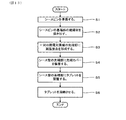
次に、本形態の温度センサ1の主要部としてのシース熱電対11を製造する方法について、図13のフローチャートを参照して説明する。
まず、シース管4内に一対の熱電対素線2が絶縁材5によって保持されたシースピン12を準備する(図13のステップS1)。図14に示すように、シースピン12においては、一対の熱電対素線2が先端側X1及び基端側X2の両端から突出している。
(Production method)
Next, a method of manufacturing the
First, the
次いで、図15に示すように、一対の熱電対素線2及びシース管4が維持された状態で、シースピン12の基端部における絶縁材5を掻き出す(ステップS2)。このとき、絶縁材5は、ショットブラスト加工等を行って掻き出すことができる。また、シース管4の基端部402には、絶縁材5が掻き出された後の空間403が形成される。次いで、図16に示すように、シースピン12の先端部から突出する、一対の熱電対素線2の先端部201同士を対面させるとともにレーザー等を用いて溶融させ、先端部同士を接合して測温接点3を形成する(ステップS3)。
Next, as shown in FIG. 15, in a state where the pair of
次いで、図17に示すように、シースピン12のシース管4の先端部401に、先端カバー42を装着し、先端カバー42を、かしめ、溶接等を行ってシース管4の先端部401に固定する(ステップS4)。なお、ステップS2を行う前に、ステップS3及びS4を行ってもよい。
Next, as shown in FIG. 17, the
次いで、同図に示すように、シース管4の基端部402の空間403内に、ガラス封止材6を形成するためのタブレット60を配置する(ステップS5)。このとき、シース管4の基端部402から突出する一対の熱電対素線2の基端部202を、タブレット60の挿通穴601に挿通させる。次いで、シース管4の基端部402及びタブレット60を加熱し、タブレット60を溶融させる(ステップS6)。
Next, as shown in the drawing, the
本形態においては、図11及び図12に示すように、第1ヒータ82A及び第2ヒータ82Bを備える加熱装置8を用いて、タブレット60を溶融させる。タブレット60を配置するセンサ中間体13(シース熱電対11の中間体)は、一対の熱電対素線2、測温接点3、シース管4、先端カバー42及び絶縁材5を備え、先端カバー42内であって絶縁材5の先端側X1に隣接する位置に気相Kが形成されたものである。そして、センサ中間体13を加熱炉81内に配置する。
In the present embodiment, as shown in FIGS. 11 and 12, the
次いで、ヒータ制御装置83によって第1ヒータ82A及び第2ヒータ82Bに通電を行い、加熱炉81内の温度が120℃以上になるように制御する。本形態においては、第1ヒータ82A及び第2ヒータ82Bによって加熱炉81内の雰囲気ガス、及びシース管4の先端部401及び基端部402を、500〜800℃に加熱する。そして、シース管4の基端部402内に配置されたタブレット60が溶融した後には、ヒータ制御装置83によって第1ヒータ82A及び第2ヒータ82Bへの通電状態を制御し、シース管4の先端部401の温度がシース管4の基端部402の温度よりも高くなる状態を形成する。
Next, the
この状態の形成により、シース管4内の先端側X1に存在する空気の密度が、シース管4内の基端側X2に存在する空気の密度よりも高くなる。また、タブレット60が溶融した状態においては、シース管4内の絶縁材5に含まれる空気が、適宜気泡となってタブレット60を通過し、シース管4の外部に抜き出される。
Due to the formation of this state, the density of the air present on the distal side X1 in the
次いで、タブレット60等の加熱を終了した後には、溶融したタブレット60が冷やされて固化していく。そして、シース管4の先端部401の温度がシース管4の基端部402の温度よりも高くなる状態において、シース管4の基端部402が、タブレット60が固化したガラス封止材6によって封止される。また、ガラス封止材6がシース管4の基端部402内に充填される。これにより、気相Kを含むシース管4内に存在する空気の密度が0.26〜0.9kg/m3の範囲内にある状態が形成される。
Next, after the heating of the
そして、シース管4内がガラス封止材6によって外部と遮断される。こうして、温度センサ1の主要部としてのシース熱電対11が製造される。
Then, the inside of the
(作用効果)
本形態の温度センサ1においては、非接地型である熱電対式の温度センサ1の応答性を改善する工夫をしている。そして、本願の発明者は、シース管4の先端部401の外周に装着された先端カバー42内に形成された気相Kの密度の違いが、温度センサ1の応答性に影響していることを見出した。
(Action effect)
In the
一般的に、接地型の温度センサの応答性が非接地型の温度センサの応答性よりも優れる性質は、接地型の温度センサにおける測温接点3とシース管4との間の熱伝導率が、非接地型の温度センサにおける測温接点3とシース管4との間の熱伝導率よりも高いことによって説明することができる。一方、温度センサの応答性の良し悪しは、熱拡散率として、測定対象ガスGと測温接点3との間での温度の伝わりやすさによって説明することができる。
In general, the property that the responsiveness of the grounding type temperature sensor is superior to the responsiveness of the non-grounding type temperature sensor is that the thermal conductivity between the
この熱拡散率α[m2/s]は、熱伝導率をk[W/(m・K)]、比熱をc[J/(kg・K)]、密度をρ[kg/m3]としたとき、α=k/(c・ρ)によって表される。つまり、温度センサの応答性は、熱伝導率が高いほど高くなる一方、比熱又は密度が高いほど低くなる性質を有する。そして、本形態の温度センサ1においては、密度を低くすることによって熱拡散率を高くし、非接地型の温度センサの応答性を改善している。
This thermal diffusivity α [m 2 / s] has a thermal conductivity of k [W / (m · K)], a specific heat of c [J / (kg · K)], and a density of ρ [kg / m 3 ]. Is expressed by α = k / (c · ρ). That is, the responsiveness of the temperature sensor is higher as the thermal conductivity is higher, but lower as the specific heat or density is higher. In the
より具体的には、本形態の温度センサ1においては、シース管4内の空気の密度、言い換えれば、先端カバー42内であって絶縁材5の先端側X1に隣接する位置に形成された気相Kの密度を、0.9kg/m3以下としている。これにより、温度センサ1の熱拡散率を高くすることができ、非接地型の温度センサの応答性を改善することができる。なお、従来の非接地型の温度センサの気相Kの密度は、常温における空気の密度として、1.2kg/m3程度であると考える。
More specifically, in the
それ故、本形態の温度センサ1によれば、測温接点の周りがフィラー等によって充填されていない非接地型の温度センサの応答性を改善することができる。
Therefore, according to the
また、本形態の温度センサ1の製造方法は、応答性が改善された非接地型の温度センサ1の製造に適したものである。特に、加熱装置8によって、シース管4の先端部401の温度がシース管4の基端部402の温度よりも高くした状態で、シース管4の基端部402をガラス封止材6によって封止することにより、シース管4内の空気の密度が0.26〜0.9kg/m3の範囲内に低くなった状態で、シース管4内を外部から封止することが容易になる。
Further, the method of manufacturing the
それ故、本形態の温度センサ1の製造方法によれば、応答性が改善された非接地型の温度センサ1を容易に製造することができる。
Therefore, according to the method of manufacturing the
なお、気相Kを含むシース管4内の気体の密度が0.9kg/m3以下となる状態は、シース管4内が大気圧よりも減圧された状態において、シース管4を封止することによっても形成することができる。この場合、大気圧よりも低い負圧状態に雰囲気ガスが減圧された真空炉内にセンサ中間体13を配置し、この真空炉内のセンサ中間体13におけるシース管4をガラス封止材6によって封止することによって、シース管4内の気体が0.9kg/m3以下である温度センサ1のシース熱電対11を形成することができる。
When the density of the gas in the
シース熱電対11を製造する際には、タブレット60を溶融させるためにシース管4の基端部402の周辺を加熱する。そのため、センサ中間体13を加熱炉81内において加熱することにより、タブレット60を溶融させることと、シース管4内の気体の密度を0.9kg/m3以下にすることとを同時に行うことができる。よって、加熱によってシース管4内の気体の密度を低くすることの方が、減圧状態によってシース管4内の気体の密度を低くすることよりも容易である。
また、気相Kを含むシース管4内の気体の密度が0.9kg/m3以下であることにより、シース管4内の気体の圧力は、大気圧よりも低い状態にある。
When manufacturing the
Further, since the density of the gas in the
(確認試験)
本確認試験においては、温度センサ1におけるシース管4内の空気の密度(気相Kの密度)[kg/m3]と、温度センサ1によって温度を測定するときの応答時間[秒]との関係を測定した。具体的には、温度センサ1によって温度を測定する測定対象ガスGの温度を、常温(25℃)から600℃に変化させ、温度センサ1の出力温度が、初期出力である25℃から最終出力である600℃になるまでの温度変化量のうちの63%分変化するまでに要する時間である63%応答時間を測定した。
(Confirmation test)
In this confirmation test, the density of the air in the
また、シース管4内の空気の密度が0.3〜1.2kg/m3の範囲内で異なる複数の温度センサ1のサンプルを準備し、この複数のサンプルについて、63%応答時間を測定した。
Moreover, the sample of the
図18には、63%応答時間を測定した結果を示す。同図において、63%応答時間は、密度が低くなるほど短くなっていることが分かる。そして、シース管4内の空気の密度が1.2kg/m3の場合には、63%応答時間が9秒程度であったことに対し、シース管4内の空気の密度が0.3kg/m3の場合には、63%応答時間が8.1秒程度であった。また、63%応答時間は、シース管4内の空気の密度が0.9kg/m3以下に低くなる場合に、顕著に短くなることが確認された。
FIG. 18 shows the result of measuring 63% response time. In the figure, it can be seen that the 63% response time is shorter as the density is lower. When the air density in the
この結果より、シース管4内の空気の密度、言い換えれば、温度センサ1内の気相Kの密度が0.9kg/m3以下であることにより、非接地型の温度センサ1の応答性が顕著に改善されることが分かった。
From this result, when the density of air in the
本発明は、実施形態のみに限定されるものではなく、その要旨を逸脱しない範囲においてさらに異なる実施形態を構成することが可能である。また、本発明は、様々な変形例、均等範囲内の変形例等を含む。 The present invention is not limited to the embodiments, and it is possible to configure further different embodiments without departing from the scope of the invention. Further, the present invention includes various modifications, modifications within the equivalent range, and the like.
1 温度センサ
2 熱電対素線
3 測温接点
4 シース管
5 絶縁材
6 ガラス封止材(封止材)
K 気相
DESCRIPTION OF
K gas phase
Claims (6)
一対の前記熱電対素線の先端同士が合わさった測温接点(3)と、
金属材料から構成され、前記測温接点を先端部(401)内又は前記先端部に装着された先端カバー(42)内に収容するとともに、一対の前記熱電対素線を基端部(402)から突出させるシース管(4)と、
絶縁材料から構成され、前記シース管内に配置されるとともに、一対の前記熱電対素線と前記シース管とを絶縁して、一対の前記熱電対素線を前記シース管に固定する絶縁材(5)と、
前記シース管の前記基端部内及び前記シース管の前記基端部に装着されたホルダ(43)内の少なくとも一方に充填されるとともに、前記シース管内を封止する封止材(6)と、を備え、
前記シース管の前記先端部内及び前記先端カバー内の少なくとも一方であって前記絶縁材の先端側に隣接する位置には、前記測温接点が収容されるとともに、密度が0.9kg/m3以下の気相(K)が形成されている、温度センサ(1)。 A pair of thermocouple wires (2) made of different metal materials;
A temperature measurement contact (3) in which the tips of the pair of thermocouple wires are combined;
The temperature measuring contact is made of a metal material, and the temperature measurement contact is accommodated in the distal end portion (401) or in the distal end cover (42) attached to the distal end portion, and a pair of the thermocouple wires at the proximal end (402) A sheath tube (4) projecting from
An insulating material (5), which is made of an insulating material, is disposed in the sheath tube, and insulates the pair of thermocouple wires from the sheath tube to fix the pair of thermocouple wires to the sheath tube. )When,
A sealing material (6) filled in at least one of the proximal end portion of the sheath tube and a holder (43) attached to the proximal end portion of the sheath tube, and sealing the sheath tube; Equipped with
The temperature measurement contact is accommodated at a position adjacent to the distal end side of the insulating material at least one of the inside of the distal end portion of the sheath tube and the distal end cover, and the density is 0.9 kg / m 3 or less A temperature sensor (1) in which a gas phase (K) is formed.
一対の前記熱電対素線の先端同士が合わさった測温接点(3)と、
金属材料から構成され、前記測温接点を先端部(401)内又は前記先端部に装着された先端カバー(42)内に収容するとともに、一対の前記熱電対素線を基端部(402)から突出させるシース管(4)と、
絶縁材料から構成され、前記シース管内に配置されるとともに、一対の前記熱電対素線と前記シース管とを絶縁して、一対の前記熱電対素線を前記シース管に固定する絶縁材(5)と、
前記シース管の前記基端部内及び前記シース管の前記基端部に装着されたホルダ(43)内の少なくとも一方に充填されるとともに、前記シース管内を封止する封止材(6)と、を備え、
前記シース管の前記先端部内及び前記先端カバー内の少なくとも一方であって前記絶縁材の先端側に隣接する位置に、前記測温接点が収容された気相(K)が形成された温度センサ(1)の製造方法において、
前記気相(K)が形成されたセンサ中間体(13)を加熱した状態において、前記封止材を、前記シース管の前記基端部内及び前記ホルダ内の少なくとも一方に充填して、前記シース管内を封止するとともに、前記気相の密度を0.9kg/m3以下にする、温度センサの製造方法。 A pair of thermocouple wires (2) made of different metal materials;
A temperature measurement contact (3) in which the tips of the pair of thermocouple wires are combined;
The temperature measuring contact is made of a metal material, and the temperature measurement contact is accommodated in the distal end portion (401) or in the distal end cover (42) attached to the distal end portion, and a pair of the thermocouple wires at the proximal end (402) A sheath tube (4) projecting from
An insulating material (5), which is made of an insulating material, is disposed in the sheath tube, and insulates the pair of thermocouple wires from the sheath tube to fix the pair of thermocouple wires to the sheath tube. )When,
A sealing material (6) filled in at least one of the proximal end portion of the sheath tube and a holder (43) attached to the proximal end portion of the sheath tube, and sealing the sheath tube; Equipped with
A temperature sensor in which a gas phase (K) in which the temperature measurement contact is accommodated is formed at a position adjacent to the tip end side of the insulating material, at least one in the tip portion and the tip cover of the sheath tube In the manufacturing method of 1),
In a state in which the sensor intermediate body (13) in which the gas phase (K) is formed is heated, the sealing material is filled in at least one of the proximal end portion of the sheath tube and the holder, A method for manufacturing a temperature sensor, wherein the inside of a tube is sealed and the density of the gas phase is set to 0.9 kg / m 3 or less.
Priority Applications (1)
| Application Number | Priority Date | Filing Date | Title |
|---|---|---|---|
| JP2018011955A JP7010027B2 (en) | 2018-01-26 | 2018-01-26 | Temperature sensor and its manufacturing method |
Applications Claiming Priority (1)
| Application Number | Priority Date | Filing Date | Title |
|---|---|---|---|
| JP2018011955A JP7010027B2 (en) | 2018-01-26 | 2018-01-26 | Temperature sensor and its manufacturing method |
Publications (2)
| Publication Number | Publication Date |
|---|---|
| JP2019128331A true JP2019128331A (en) | 2019-08-01 |
| JP7010027B2 JP7010027B2 (en) | 2022-01-26 |
Family
ID=67473167
Family Applications (1)
| Application Number | Title | Priority Date | Filing Date |
|---|---|---|---|
| JP2018011955A Expired - Fee Related JP7010027B2 (en) | 2018-01-26 | 2018-01-26 | Temperature sensor and its manufacturing method |
Country Status (1)
| Country | Link |
|---|---|
| JP (1) | JP7010027B2 (en) |
Citations (5)
| Publication number | Priority date | Publication date | Assignee | Title |
|---|---|---|---|---|
| JPS49105178U (en) * | 1972-12-07 | 1974-09-09 | ||
| JPS55118140U (en) * | 1979-02-14 | 1980-08-21 | ||
| JPS62184442U (en) * | 1986-05-16 | 1987-11-24 | ||
| JPH09250952A (en) * | 1996-01-08 | 1997-09-22 | Matsushita Electric Ind Co Ltd | Temperature detection device and automobile using the same |
| US20070258506A1 (en) * | 2006-05-02 | 2007-11-08 | Schwagerman William H | Temperature sensors and methods of manufacture thereof |
-
2018
- 2018-01-26 JP JP2018011955A patent/JP7010027B2/en not_active Expired - Fee Related
Patent Citations (5)
| Publication number | Priority date | Publication date | Assignee | Title |
|---|---|---|---|---|
| JPS49105178U (en) * | 1972-12-07 | 1974-09-09 | ||
| JPS55118140U (en) * | 1979-02-14 | 1980-08-21 | ||
| JPS62184442U (en) * | 1986-05-16 | 1987-11-24 | ||
| JPH09250952A (en) * | 1996-01-08 | 1997-09-22 | Matsushita Electric Ind Co Ltd | Temperature detection device and automobile using the same |
| US20070258506A1 (en) * | 2006-05-02 | 2007-11-08 | Schwagerman William H | Temperature sensors and methods of manufacture thereof |
Also Published As
| Publication number | Publication date |
|---|---|
| JP7010027B2 (en) | 2022-01-26 |
Similar Documents
| Publication | Publication Date | Title |
|---|---|---|
| EP2428781B1 (en) | Temperature sensor and temperature sensor system | |
| US11454551B2 (en) | Temperature sensor and temperature measuring device | |
| US7982580B2 (en) | High vibration thin film RTD sensor | |
| US7458718B2 (en) | Temperature sensor that achieves a fast response in an exhaust gas environment | |
| JP6265001B2 (en) | Temperature sensor | |
| JP5155246B2 (en) | Temperature sensor | |
| JP2004317499A (en) | Temperature sensor | |
| JP6888439B2 (en) | Temperature sensor | |
| JP5252631B2 (en) | Temperature sensor and manufacturing method thereof | |
| JP2009270989A (en) | Temperature sensor | |
| JP5123058B2 (en) | Manufacturing method of temperature sensor | |
| JP7010027B2 (en) | Temperature sensor and its manufacturing method | |
| US11237064B2 (en) | Temperature sensor | |
| JP2017538928A (en) | Temperature sensor | |
| JP4203346B2 (en) | Manufacturing method of temperature sensor | |
| US2794059A (en) | Sealed tip thermocouples | |
| WO2019151167A1 (en) | Temperature sensor | |
| JP2017015504A (en) | Temperature sensor | |
| JP5123344B2 (en) | Temperature sensor | |
| CN223678651U (en) | Thermocouple | |
| JPH09106892A (en) | SUS sheath type component and manufacturing method thereof | |
| JPH0712652A (en) | Sheath type thermocouple | |
| JPS5931874B2 (en) | Thermal-electric conversion element |
Legal Events
| Date | Code | Title | Description |
|---|---|---|---|
| A621 | Written request for application examination |
Free format text: JAPANESE INTERMEDIATE CODE: A621 Effective date: 20201209 |
|
| A977 | Report on retrieval |
Free format text: JAPANESE INTERMEDIATE CODE: A971007 Effective date: 20211006 |
|
| A131 | Notification of reasons for refusal |
Free format text: JAPANESE INTERMEDIATE CODE: A131 Effective date: 20211012 |
|
| A521 | Request for written amendment filed |
Free format text: JAPANESE INTERMEDIATE CODE: A523 Effective date: 20211201 |
|
| TRDD | Decision of grant or rejection written | ||
| A01 | Written decision to grant a patent or to grant a registration (utility model) |
Free format text: JAPANESE INTERMEDIATE CODE: A01 Effective date: 20211214 |
|
| A61 | First payment of annual fees (during grant procedure) |
Free format text: JAPANESE INTERMEDIATE CODE: A61 Effective date: 20211227 |
|
| R151 | Written notification of patent or utility model registration |
Ref document number: 7010027 Country of ref document: JP Free format text: JAPANESE INTERMEDIATE CODE: R151 |
|
| LAPS | Cancellation because of no payment of annual fees |