JP2019131237A - Mixing cap - Google Patents
Mixing cap Download PDFInfo
- Publication number
- JP2019131237A JP2019131237A JP2018014359A JP2018014359A JP2019131237A JP 2019131237 A JP2019131237 A JP 2019131237A JP 2018014359 A JP2018014359 A JP 2018014359A JP 2018014359 A JP2018014359 A JP 2018014359A JP 2019131237 A JP2019131237 A JP 2019131237A
- Authority
- JP
- Japan
- Prior art keywords
- outer lid
- opening
- lid
- mixing cap
- top plate
- Prior art date
- Legal status (The legal status is an assumption and is not a legal conclusion. Google has not performed a legal analysis and makes no representation as to the accuracy of the status listed.)
- Granted
Links
Images


Landscapes
- Closures For Containers (AREA)
- Package Specialized In Special Use (AREA)
Abstract
Description
本発明は、主剤が充填された容器の口部に装着され、副剤を容器内へ混合可能な混合キャップに関する。 The present invention relates to a mixing cap that is attached to a mouth portion of a container filled with a main agent and can mix an auxiliary agent into the container.
従来、主剤が充填された容器の口部に装着され、ポーションカップ内に充填された副剤を任意のタイミングで取り出し容器内の主剤と混合可能な混合キャップとして、容器の口部に装着可能な内蓋と、副剤を充填したポーションカップとで構成された混合キャップが特許文献1で公知である。
この特許文献1で公知の混合キャップは、円筒状に形成されたキャップ本体(第二の部材4)の半径方向中心から放射状に延びる開封用カッター(切断片42)を有し、内蓋(第二の部材4)の上部には開封面(閉塞片8)を下に向けたポーションカップ(第一の部材2)が係合しており、ポーションカップ(第一の部材2)を押し込むことで、開封用カッター(切断片42)によって開封面(閉塞片8)を切り裂き、ポーションカップ(第一の部材2)内に充填されている副剤を容器内へ落下させて主剤と混合するものである。
Conventionally, it can be attached to the mouth of a container as a mixing cap that is attached to the mouth of a container filled with the main agent and can take out the auxiliary agent filled in the portion cup at any timing and mix it with the main agent in the container. A mixing cap composed of an inner lid and a portion cup filled with an auxiliary agent is known from Patent Document 1.
The mixing cap known in Patent Document 1 has an opening cutter (cut piece 42) extending radially from the center in the radial direction of a cap body (second member 4) formed in a cylindrical shape. The upper part of the second member 4) is engaged with a portion cup (first member 2) with the opening surface (blocking piece 8) facing downward, and the portion cup (first member 2) is pushed in. The opening surface (blocking piece 8) is cut by the opening cutter (cutting piece 42), and the secondary agent filled in the portion cup (first member 2) is dropped into the container and mixed with the main agent. is there.
ところが、上記特許文献で公知の混合キャップは、未だ改善の余地があった。
すなわち、ポーションカップ(第一の部材2)内の副剤を主剤と混合し終えた後、容器から内容物を取り出すには、内蓋(第二の部材4)を容器口部から外す必要があり、例えば、シャンプーや調味料等の、片手で使用する頻度が高く、容器内に水や異物が入りやすい使用環境では、迅速な容器の開閉を行えない虞があった。
また、容器内の内容物が高粘度原液の場合、内蓋(第二の部材4)を容器口部から外して内容物を取り出す際、容器口部の外周面に内容物が付着することで、内蓋(第二の部材4)を容器口部に装着しにくくなる虞があった。
However, the mixing caps known in the above-mentioned patent documents still have room for improvement.
That is, in order to take out the contents from the container after the auxiliary agent in the portion cup (first member 2) has been mixed with the main agent, it is necessary to remove the inner lid (second member 4) from the container mouth. For example, there is a possibility that the container cannot be opened / closed quickly in a use environment such as shampoo or seasoning that is frequently used with one hand and water or foreign substances are likely to enter the container.
In addition, when the contents in the container are a high-viscosity stock solution, when the contents are taken out by removing the inner lid (second member 4) from the container mouth, the contents adhere to the outer peripheral surface of the container mouth. The inner lid (second member 4) may not be easily attached to the container mouth.
また、ポーションカップ(第一の部材2)が十分に降下する前にポーションカップ(第一の部材2)の開封面(閉塞片8)が開封され始めるため、ポーションカップ(第一の部材2)と内蓋(第二の部材4)との隙間から、開封したポーションカップ(第一の部材2)内の副剤が容器外へ漏出するおそれがあった。
また、開封前のポーションカップ(第一の部材2)の降下を制限する制限片がポーションカップ(第一の部材2)に設けられているが、制限片は円筒状の内蓋(第二の部材4)よりも半径方向外方へ突出しているため、搬送時における混合キャップの周方向の向きに注意する必要があるとともに、突出した制限片に不意に触れてしまい、開封時以外で制限片を破断してしまうおそれがあった。
Further, since the opening surface (blocking piece 8) of the portion cup (first member 2) begins to be opened before the portion cup (first member 2) is sufficiently lowered, the portion cup (first member 2). There was a risk that the secondary agent in the opened portion cup (first member 2) would leak out of the container from the gap between the container and the inner lid (second member 4).
Moreover, although the restriction piece which restrict | limits the fall of the portion cup (1st member 2) before opening is provided in the portion cup (1st member 2), a restriction piece is a cylindrical inner lid (2nd Since it protrudes outward in the radial direction from the member 4), it is necessary to pay attention to the circumferential direction of the mixing cap at the time of conveyance, and the protruding restriction piece is abruptly touched. Could break.
本発明は、これらの問題点を解決するものであり、簡単な構成で、ポーションカップの開封面を十分に開封できるとともに、混合キャップ及び混合キャップを装着した容器の外部との密閉性を保ち、開封されたポーションカップから取り出した副剤を迅速に容器内の主剤側へ落下し混合させることができ、混合キャップを容器の口部から取り外すことなく混合後の内容物を注出可能な混合キャップを提供することを目的とするものである。 The present invention solves these problems, and with a simple configuration, the opening surface of the portion cup can be sufficiently opened, and the mixing cap and the outside of the container equipped with the mixing cap are kept hermetically sealed, A mixing cap that can quickly drop the adjunct removed from the opened potion cup to the main agent in the container for mixing, and dispense the mixed contents without removing the mixing cap from the mouth of the container. Is intended to provide.
本発明の混合キャップは、主剤が充填された容器の口部に装着され、副剤を容器内へ混合可能な混合キャップであって、該混合キャップは、外蓋と、開封用カッターを有する内蓋と、充填された副剤を保持したまま密封可能な開封面を有するポーションカップを保持可能な保持空間とを有し、前記外蓋は、前記内蓋と係合可能且つ相対的に回転可能に構成され、外蓋天面と、前記外蓋天面から下方に延びる筒状壁と、前記外蓋天面から下方に延びる、前記筒状壁より外方に形成された外蓋壁部と、前記外蓋天面から下方に延びる、前記筒状壁と前記外蓋壁部との間に形成された中間壁部とを有し、前記外蓋天面には、前記筒状壁より周方向外方に位置し外蓋天面を貫通した注出孔と、前記注出孔を開閉可能な密閉カバーが設けられ、前記保持空間は、前記筒状壁の内周側に前記ポーションカップを収容可能に構成され、前記中間壁部には、前記中間壁部の下端から下方に延びる垂下片が設けられ、前記内蓋は、前記容器口部と係合可能に構成され、頂板部と、前記頂板部から上方に延び前記外蓋壁部の内側に係合可能な筒状突起とを有し、前記頂板部には、前記頂板部の上下を貫通し、前記容器口部と連通可能な貫通孔が設けられ、前記筒状突起の内周面には、半径方向内方に膨出形成された回転防止部と、前記回転防止部よりも上端面が低く形成された落下規制部とが設けられ、前記回転防止部の一方と前記落下規制部の一方とは互いに隣接し、前記回転防止部の他方と前記落下規制部の他方との間には、落下誘導部が形成されており、前記回転防止部と、前記落下規制部と、前記落下誘導部とは、外蓋と内蓋とが係合した際、前記垂下片の下端と同一円周上に位置するように構成され、前記垂下片は、前記上蓋を開栓する際に、前記落下誘導部と周方向に合致する位置まで回転した後、前記内蓋と相対的に上下移動可能に構成され、前記開封用カッターは、前記頂板部の、前記ポーションカップの前記開封面と対向する位置に設けられていることにより、前記課題を解決するものである。 The mixing cap of the present invention is a mixing cap that is attached to the mouth of a container filled with the main agent and can mix the auxiliary agent into the container. The mixing cap includes an outer lid and an opening cutter. A holding space capable of holding a portion cup having a lid and a sealing surface that can be sealed while holding the filled secondary agent, and the outer lid is engageable with the inner lid and is rotatable relative to the inner lid. An outer lid top surface, a cylindrical wall extending downward from the outer lid top surface, and an outer lid wall portion extending outward from the cylindrical wall and extending downward from the outer lid top surface. An intermediate wall portion formed between the cylindrical wall and the outer lid wall portion that extends downward from the outer lid top surface, and the outer lid top surface is more circumferential than the cylindrical wall. A holding hole that is located outward in the direction and penetrates the top surface of the outer lid, and a sealing cover that can open and close the pouring hole is provided, Between, it is configured to be able to accommodate the portion cup on the inner peripheral side of the cylindrical wall, the intermediate wall portion is provided with a hanging piece extending downward from the lower end of the intermediate wall portion, It is configured to be engageable with the container mouth portion, and has a top plate portion, and a cylindrical protrusion that extends upward from the top plate portion and can be engaged with the inside of the outer lid wall portion. A through-hole penetrating the top and bottom of the top plate portion and communicating with the container mouth portion is provided, and an anti-rotation portion bulging radially inward on the inner peripheral surface of the cylindrical projection, and the rotation A drop restricting portion having an upper end surface lower than the preventing portion, and one of the rotation preventing portions and one of the drop restricting portions are adjacent to each other, and the other of the rotation preventing portions and the drop restricting portion A drop guiding portion is formed between the other, the rotation preventing portion, the drop regulating portion, and the front When the outer lid and the inner lid are engaged with each other, the drop guiding portion is configured to be positioned on the same circumference as the lower end of the hanging piece, and the hanging piece is configured to open the upper lid. After rotating to a position that matches the drop guiding portion in the circumferential direction, the upper lid is configured to be movable up and down relative to the inner lid, and the opening cutter is opposed to the opening surface of the portion cup of the top plate portion. The above-mentioned problem is solved by being provided at the position to be operated.
請求項1に係る発明の混合キャップによれば、該混合キャップの外蓋天面は、外蓋天面を貫通した注出孔と、注出孔を開閉可能な密閉カバーが設けられているため、混合キャップ内の副剤を主剤と混合させた後、密閉カバーを開けることで、混合キャップを容器口部から外すことなく、注出孔から容器内の内容物を取り出すことができる。
また、保持空間は、筒状壁の内周側にポーションカップを収容可能に構成されているため、複数の種類の副剤を使用して生産する場合でも、ポーションカップの形状が統一されていれば、生産ラインの型替えの必要なく混合キャップの生産が可能である。
According to the mixing cap of the invention according to claim 1, the top surface of the outer cap of the mixing cap is provided with the pouring hole penetrating the outer lid top surface and the sealing cover that can open and close the pouring hole. After the auxiliary agent in the mixing cap is mixed with the main agent, the contents in the container can be taken out from the dispensing hole without removing the mixing cap from the container opening by opening the hermetic cover.
In addition, since the holding space is configured so that the portion cup can be accommodated on the inner peripheral side of the cylindrical wall, the shape of the portion cup can be unified even when producing using a plurality of types of auxiliary agents. For example, mixed caps can be produced without the need to change the production line.
さらに、既に副剤が充填されているポーションカップを保持空間内に配置するため、混合キャップの組立て作業時に副剤が他の部品に付着して汚染してしまうことを抑制できる。
また、副剤は、容器口部と連通可能な貫通孔を通るため、確実に容器内へ落下できる。
Furthermore, since the portion cup already filled with the auxiliary agent is disposed in the holding space, it is possible to prevent the auxiliary agent from adhering to other parts and being contaminated during the assembly operation of the mixing cap.
Moreover, since the secondary agent passes through the through-hole that can communicate with the container mouth portion, it can reliably fall into the container.
さらに、外蓋の中間壁部には、中間壁部の下端から下方に延びる垂下片が設けられ、内蓋の筒状突起の内周面には、回転防止部と、落下規制部と、落下誘導部が形成されているため、垂下片が落下規制部に当接した際、外蓋は落下規制部と垂下片が当接している限り内蓋側へ落下することがないため、使用時以外にポーションカップの開封面と開封用カッターとが接触することを防ぐことができる。
また、落下規制部に隣接した回転防止部側には、垂下片が干渉することで外蓋の回転を防止できるとともに、外蓋を回転して落下規制部から落下誘導部側へ垂下片を移動し、落下誘導部へ落下させることで、外蓋全体が内蓋側へ落下でき、ポーションカップの開封面を、頂板部に形成された開封用カッターによって開封することができる。
Further, a hanging piece extending downward from the lower end of the intermediate wall portion is provided on the intermediate wall portion of the outer lid, and an anti-rotation portion, a drop regulating portion, and a drop are provided on the inner peripheral surface of the cylindrical protrusion of the inner lid. Since the guide part is formed, when the drooping piece comes into contact with the drop restricting part, the outer lid does not fall to the inner cover side as long as the drop restricting part and the drooping piece are in contact. It is possible to prevent the opening surface of the potion cup from coming into contact with the opening cutter.
In addition, on the anti-rotation part side adjacent to the drop restricting part, the drooping piece can prevent the outer lid from rotating, and the outer cover can be rotated to move the drooping piece from the drop restricting part to the drop guiding part side. And by dropping to the drop guiding part, the entire outer lid can fall to the inner lid side, and the opening surface of the portion cup can be opened by the opening cutter formed on the top plate part.
請求項2に記載の構成によれば、筒状壁の外周面の一部は、上下方向に亘って縮径部を有した非円形形状であるため、容器口部から注出孔へ向かう内容物が流れやすく短い流路を形成でき、容器内の内容物をより一層効率よく取り出すことができる。 According to the structure of Claim 2, since a part of outer peripheral surface of a cylindrical wall is non-circular shape which has a diameter-reduced part over the up-down direction, the content which goes to a pouring hole from a container opening part A short flow path can be formed in which the material can easily flow, and the contents in the container can be taken out more efficiently.
請求項3に記載の構成によれば、ポーションカップの開封面の周囲に設けられたフランジの外周縁は、筒状壁と相似の関係にある非円形形状であるため、開封面の開栓後、筒状壁の下端でフランジを全体的に押さえ込んで安定して固定できる。 According to the structure of Claim 3, since the outer periphery of the flange provided in the circumference | surroundings of the opening surface of a portion cup is a non-circular shape similar to a cylindrical wall, after opening of an opening surface The flange can be pressed down and fixed stably at the lower end of the cylindrical wall.
請求項4に記載の構成によれば、垂下片の下部には、垂下片の下部から半径方向内方に膨出形成された保持リブが設けられているため、保持リブの上にポーションカップの下端縁を載せることで、ポーションを安定した姿勢で保持することができる。
また、保持リブの上下方向の厚み分、頂板部とポーションカップとの間に空間を形成でき、容器内の内容物を取り出す際、注出孔に向かう流路をポーションカップで塞ぐことなく十分に広く確保できる。
According to the configuration of the fourth aspect of the present invention, since the holding rib formed to bulge inward in the radial direction from the lower portion of the drooping piece is provided at the lower portion of the drooping piece, By placing the lower edge, the potion can be held in a stable posture.
In addition, a space can be formed between the top plate portion and the portion cup by the thickness of the holding rib in the vertical direction, and when taking out the contents in the container, the flow path toward the pouring hole is sufficiently blocked with the portion cup. Widely secured.
請求項5に記載の構成によれば、保持リブは、フランジを保持可能に形成されているため、開封前のポーションカップのフランジを、保持リブに載せることで、使用時以外に開封用カッターが開封面に触れて開封することを防止できるとともに、筒状壁の下端と保持リブとでフランジを全体的に挟み込んで安定して固定でき、使用時に確実に開封用カッターで開封面を開封することができる。 According to the structure of Claim 5, since the holding rib is formed so that the flange can be held, by placing the flange of the portion cup before opening on the holding rib, the opening cutter can be used in addition to the time of use. The opening surface can be prevented from being touched and opened, and the flange can be sandwiched between the lower end of the cylindrical wall and the holding rib to be stably fixed, and the opening surface can be reliably opened with an opening cutter during use. Can do.
請求項6に記載の構成によれば、混合キャップは、開封時に保持リブの下端と頂板部とが当接した際に、ポーションカップと頂板部との間に第1流路を形成するため、混合した内容物を取り出す際、ポーションカップによって内容物の流路がふさがれることなく、容器口部から注出孔までの経路を短く構成でき、迅速に内容物を取り出すことができる。 According to the configuration of claim 6, the mixing cap forms a first flow path between the portion cup and the top plate portion when the lower end of the holding rib and the top plate portion abut upon opening. When the mixed contents are taken out, the passage from the container mouth to the pouring hole can be shortened without the passage of the contents being blocked by the portion cup, and the contents can be taken out quickly.
請求項7に記載の構成によれば、外蓋の注出孔は、縮径部の外方に形成され、縮径部の外方と筒状突起の内面に第2流路が形成され、注出孔と第2流路が連通しているため、容器口部から第2流路へ流入した内容物を注出孔へ短い流路で流入でき、内容物をさらに一層効率よく取り出すことができる。 According to the structure of Claim 7, the extraction | pouring hole of an outer cover is formed in the outward of a reduced diameter part, and the 2nd flow path is formed in the outer side of a reduced diameter part and the inner surface of a cylindrical protrusion, Since the extraction hole communicates with the second flow path, the contents flowing into the second flow path from the container mouth can be flowed into the extraction hole with a short flow path, and the contents can be taken out even more efficiently. it can.
請求項8に記載の構成によれば、落下規制部の少なくとも1つの上面は、筒状突起の内周面から、筒状突起の中心軸側にむかって徐々に上方に向かい、垂下片の下端を筒状突起の外周面に当接可能な傾斜部を有しているため、落下規制部に垂下片が当接した際、垂下片が落下規制部よりも半径方向内方へ移動して外蓋全体がさらに落下してしまうことを確実に防ぐことができる。 According to the configuration of claim 8, at least one upper surface of the drop restricting portion gradually moves upward from the inner peripheral surface of the cylindrical protrusion toward the central axis side of the cylindrical protrusion, and the lower end of the drooping piece. Since there is an inclined part that can contact the outer peripheral surface of the cylindrical projection, when the drooping piece comes into contact with the drop restricting part, the drooping piece moves radially inward from the drop restricting part and comes out. It can prevent reliably that the whole lid | cover will fall further.
請求項9に記載の構成によれば、開封用カッターは、貫通孔の外周縁に沿って弧状に延在しているため、ポーションカップの開封面の縁に沿って大きく開口できるとともに、副剤を迅速に貫通孔へ流入できる。
また、開封面のめくり上げ方向に向かって徐々に下方に傾斜しているため、開封用カッターは開封面のめくり上げ方向と反対側の位置から開封面に接触し、開封する力を一転に集中させ、めくり上げ方向に向かって徐々に開封することができ、より確実に開封面を開封することができる。
According to the configuration of the ninth aspect, since the opening cutter extends in an arc shape along the outer peripheral edge of the through-hole, the opening cutter can be greatly opened along the edge of the opening surface of the portion cup, and the auxiliary agent Can quickly flow into the through hole.
Also, since the opening surface is gradually inclined downward in the direction of turning up, the opening cutter comes into contact with the opening surface from the opposite side of the opening surface in the direction of turning up and concentrates the opening force. And can be gradually opened in the flip-up direction, and the opening surface can be opened more reliably.
請求項10に記載の構成によれば、頂板部には、上方に延びる押上げリブを有しているため、ポーションカップの開封面を押し上げることで、開封面の撓み弛みを解消し、開封用カッターを開封面に食い込みやすくできるとともに、開封用カッターが食い込んだ開封面の開口面積を確実に広げることができる。
さらに、押上げリブは開封面のめくり上げ方向に向かって徐々に下方に傾斜しているため、開封面のうち、開封用カッターが最初に接触する位置の撓みをより確実に解消できるとともに、開封用カッターが開封面に食い込む前に、開封面の他の位置に押上げリブが当接することを防ぐことで、開封用カッターを開封面により食い込みやすくできる。
According to the configuration of the tenth aspect, since the top plate portion has the push-up rib extending upward, by pushing up the opening surface of the portion cup, the bending looseness of the opening surface is eliminated, and the opening plate is opened. The cutter can easily bite into the opening surface, and the opening area of the opening surface into which the opening cutter bites can be surely expanded.
Furthermore, since the push-up rib is gradually inclined downward in the direction of turning up the opening surface, it is possible to more reliably eliminate the bending of the opening surface where the opening cutter first contacts, and to open the opening surface. By preventing the push-up rib from coming into contact with another position of the opening surface before the cutting cutter bites into the opening surface, the opening cutter can be easily bited by the opening surface.
以下に、本発明の一実施形態に係る混合キャップ100について、図面に基づいて説明する。なお、混合キャップ100に嵌合する容器は、容器口部Bのみを図示する。
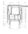
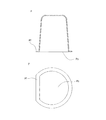
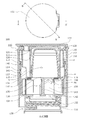
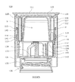
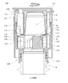
混合キャップ100は、主剤が充填された容器の口部Bに装着され、副剤Sを取り出し容器内へ混合可能なものであり、図1および図2に示すように、外蓋110と、開封用カッター143を有する内蓋130と、充填された副剤Sを保持したまま密封可能な開封面Psを有するポーションカップPを保持可能な保持空間120とが設けられている。
Below, the mixing
The mixing
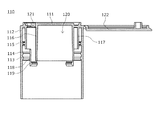
外蓋110は内蓋130と係合可能且つ相対的に回転可能に構成され、図3および図4に示すように、外蓋天面111と、外蓋天面111から下方に延びる筒状壁116と、外蓋天面111から下方に延びる、筒状壁116より外方に形成された外蓋壁部112と、外蓋天面111から下方に延びる、筒状壁116と外蓋壁部112との間に形成された中間壁部117とを有している。
外蓋天面111には、筒状壁116より周方向外方に位置し外蓋天面111を貫通した注出孔121と、注出孔121を開閉可能な密閉カバー122が設けられている。
The
The outer lid
保持空間120は、筒状壁116の内周側にポーションカップPを収容可能に構成されている。
中間壁部117には、中間壁部117の下端から下方に延びる複数の垂下片118(本実施形態では4個)が設けられており、垂下片118の側端の一方は、筒状壁116と連絡片123によって接続されている。
垂下片118の下端には、半径方向内方に膨出形成された保持リブ119が設けられている。
The holding
The
A holding
筒状壁116の外周面のうち、外蓋110の中心軸からみて注出孔121側に位置する箇所には、上下方向に亘って平面に形成された縮径部124が設けられている。
外蓋壁部112の内周面には、第1仮止めリブ113と、第1仮止めリブ113よりも上方に設けられた第2仮止めリブ114と、第2仮止めリブ114よりも上方に設けられた抜け止めリブ115とが、それぞれ半径方向内方に膨出形成されている。
In the outer peripheral surface of the
On the inner peripheral surface of the
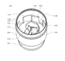
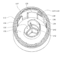
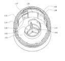
内蓋130は、容器口部Bと係合可能に構成され、図5および図6に示すように、頂板部131と、頂板部131から上方に延び外蓋壁部112の内側に係合可能な筒状突起134と、頂板部131から下方に延び容器口部Bのとネジ係合可能なスカート壁133とを有している。
頂板部131には、頂板部131の上下を貫通し、容器口部Bと連通可能な貫通孔132、頂板部131から上方に延び、貫通孔132の外周縁に沿って弧状に延在している開封用カッター143と、開封用カッター143に囲繞される内部領域には、頂板部131から上方に延び、頂板部131の中心から3方向に放射状に形成された押上げリブ142が設けられている。
押上げリブ142と開封用カッター143は、開封用カッター143が形成する弧の開放側に向かって徐々に下方に傾斜するように形成されている。
The
The
The lifting
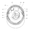
筒状突起134の内周面には、半径方向内方に膨出形成された回転防止部135と、回転防止部135よりも上端面が低く形成された落下規制部136とが互いの一方の側面が隣接するように設けられ、回転防止部135の側面の他方と落下規制部136の側面の他方との間には、落下誘導部139が形成されている。
回転防止部135と、落下規制部136と、落下誘導部139とは、外蓋110と内蓋130とが係合した際、垂下片118の下端と同一円周上に位置するように構成されている。
On the inner peripheral surface of the
The
落下規制部136の上面の少なくとも1つの上面は、筒状突起134の内周面から、筒状突起134の中心軸にむかって徐々に上方に向かう傾斜部137を有している。
また、落下規制部136の上面の少なくとも1つの上面の落下誘導部139側には、上方に延びる逆転防止部138が形成されている。
筒状突起134の内周面の上部には、半径方向内方に膨出形成された密着リング140が設けられ、筒状突起134の外周面には、半径方向外方に膨出形成された係止リブ141が設けられている。
At least one upper surface of the upper surface of the
In addition, a reverse
A
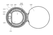
ポーションカップPは、図7に示すように、下面に設けられた開封面Psが、フランジPfに接続され、ポーションカップP内を密閉している。
また、ポーションカップPの下面の概形は、円弧の両端を直線で結んだD型の形状を有している。
As shown in FIG. 7, the portion cup P has an opening surface Ps provided on the lower surface thereof connected to the flange Pf to seal the inside of the portion cup P.
Moreover, the rough shape of the lower surface of the portion cup P has a D-shape in which both ends of the arc are connected by a straight line.
次に、混合キャップ100の組み立てについて、図8乃至図10に基づいて説明する。
Next, the assembly of the mixing
まず、ポーションカップPを外蓋110の保持空間120内にセットする。
このとき、ポーションカップPのフランジPfを、筒状壁116の下端と保持リブ119との間に挟み込むような位置に固定することで、ポーションカップPが保持空間120内から落下することなく確実に保持することができる。
First, the portion cup P is set in the holding
At this time, by fixing the flange Pf of the portion cup P at such a position as to be sandwiched between the lower end of the
次に、ポーションカップPを挿入した外蓋110を、内蓋130に被せる。
このとき、外蓋壁部112と中間壁部117との間に筒状突起134を挿入するように外蓋110を内蓋130に被せると、筒状突起134の内周面の密着リング140は、中間壁部117の外周面に周方向均一に接触する。
また、筒状突起134の外周面の係止リブ141は、外蓋壁部112の内周面の第1仮止めリブ113と第2仮止めリブ114の間に挟まるように係合し、垂下片118の下端は、落下規制部136の上端に接触する。
Next, the
At this time, when the
Further, the engaging
第1仮止めリブ113と第2仮止めリブ114との間に係止リブ141を係合させることで、混合キャップ100の搬送時にかかる程度の衝撃や振動では、外蓋110と内蓋130との上下方向の相対的な位置関係が変わることがなく、開封面Psに開封用カッター143が触れることがない。
また、垂下片118が落下規制部136から脱落することがないよう、本実施形態では傾斜部137が設けられており、落下規制部136に垂下片118が当接した際、垂下片118は傾斜部137によって、垂下片118の下端を筒状突起134の内周面に沿って移動する。
By engaging the locking
Further, in this embodiment, an
さらに、逆転防止部138が設けられた落下規制部136に垂下片118が当接していると、混合キャップ100の搬送時等にかかる程度の衝撃や振動によって、外蓋110と内蓋130との周方向の相対的な位置関係がずれるような力が発生した場合でも、垂下片118は落下規制部136に隣接する回転防止部135と、逆転防止部138とによって移動が規制されているため、落下誘導部139へ垂下片118が不意に落下してしまうことを防ぐことができる。
Further, when the hanging
次に、混合キャップ100による、ポーションカップPの副剤Sと、容器内の主剤との混合手順および注出手順について、図11乃至図15に基づいて説明する。
なお、説明のため、図の容器の向きはすべて正立状態のものを使用する。
Next, a mixing procedure and a dispensing procedure of the auxiliary agent S of the portion cup P and the main agent in the container by the mixing
For the sake of explanation, the containers shown in the figure are all upright.
まず、図11および図12に示すように、容器口部Bに混合キャップ100を装着し、外蓋110を時計回りに回転させる。
外蓋110は内蓋130に対して相対的に回転するため、外蓋110を回転させると、垂下片118は、落下規制部136に隣接する落下誘導部139側へ徐々に移動する。
First, as shown in FIGS. 11 and 12, the mixing
Since the
このとき、逆転防止部138の落下規制部136側の側面が、時計回り方向に進むにつれて筒状突起134の内周面から半径方向内方側へ向かう傾斜面で形成されているため、外蓋110を回転させる力によって、垂下片118は逆転防止部138を避けるように半径方向内方へ変形しながら、落下誘導部139側へ移動する。
また、逆転防止部138の落下誘導部139側の側面は、筒状突起134の内周面から半径方向内方へ向かう平面で形成されているため、垂下片118が逆転防止部138を乗越えた後、外蓋110を反時計回りに回転させようとしても、垂下片118が逆転防止部138を乗り越えることができず、外蓋110と内蓋130との周方向の相対的な位置関係を変更することはできない。
At this time, since the side surface of the reverse
In addition, since the side surface of the
垂下片118を落下誘導部139上に移動させた後、外蓋110を押し込むと、図13および図14に示すように、垂下片118は落下誘導部139の最下端まで移動するため、外蓋110全体が内蓋130側移動し、開封面Psに開封用カッター143が食い込んで複数の破線状の亀裂を形成し、亀裂から副剤Sが少しずつ流出し、貫通孔132を通って容器内へ入り始める。
後述するが、ここで外蓋110を押し込んだ際、保持リブ119の高さの分だけ頂板部131とフランジPfには高さ方向に空間が形成され、内容物M取り出し時の第1流路L1となる。
When the
As will be described later, when the
また、縮径部124の外方と筒状突起134の内面に、注出孔121と連通する第2流路L2が形成される。
このとき、係止リブ141は第2仮止めリブ114と抜け止めリブ115を乗り越えて、抜け止めリブ115よりも上方まで移動する。これによって、外蓋110の、内蓋130から離脱する方向への移動を防ぐことができる。
Further, a second flow path L <b> 2 communicating with the
At this time, the locking
また、押上げリブ142と開封用カッター143は、開封用カッター143が形成する弧の開放側に向かって徐々に下方に傾斜するように形成されているため、開封面Psのうち、開封用カッター143が最初に接触する位置の撓みをより確実に解消でき、開封用カッター143を開封面Psに食い込みやすくできるとともに、開封用カッター143による開封面Psを開封する力を一点に集中させることができ、より確実に開封面Psを開封することができる。
外蓋110を内蓋130側に押込みきる間に、開封用カッター143によって開封面Psは完全に開封され、副剤Sはすべて容器へ流入する。
Further, since the lifting
While the
このとき、密着リング140は、中間壁部117の外周面と周方向均一に密着しているため、副剤Sと主剤とを混合する際に容器を振っても、外蓋110と内蓋130との間から副剤Sや主剤が容器外へ漏れ出ることはない。
At this time, since the
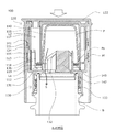
次に、副剤Sを容器内の主剤と混合した内容物Mを取り出す。 Next, the content M obtained by mixing the auxiliary agent S with the main agent in the container is taken out.
図15に示すように、外蓋110の密閉カバー122を展開することで、外蓋天面111の注出孔121が開く。
容器を注出孔121側に傾けると、内容物Mは容器口部Bから貫通孔132を通り、頂板部131とフランジPfとの間に形成された第1流路L1を経由し、筒状壁116の外側の第2流路L2を通って注出孔121へ向かう。
As shown in FIG. 15, by opening the sealing
When the container is tilted toward the pouring
このとき、ポーションカップPは、フランジPfを筒状壁116の下端と保持リブ119とで位置固定されているため、保持リブ119の高さ分だけ頂板部131から離れた位置で保持し、第1流路L1が形成され、落下誘導部139の下端が頂板部131から底上げされている場合、頂板部131からさらに離れた位置で保持されている。
さらに、筒状壁116の外周面のうち、外蓋110の中心軸からみて注出孔121側に位置する箇所には、上下方向に亘って平面に形成された縮径部124が設けられているため、内容物Mが貫通孔132から注出孔121まで向かう流路を十分広く確保できる。
At this time, the potion cup P holds the flange Pf at the position separated from the
Further, on the outer peripheral surface of the
これによって、容器口部Bから混合キャップ100を外すことなく、内容物Mを取り出すことが可能となり、内容物Mの取り出し操作が片手で簡単に操作できるとともに、内容物Mの取り出し操作中における容器内への異物の混入を抑制できる。
また、内蓋130の密着リング140が中間壁部117の内周面に密着しているため、筒状突起134と中間壁部117の間から内容物Mが漏れ出ることはない。
As a result, the contents M can be taken out without removing the mixing
In addition, since the
以上、本発明の実施形態を詳述したが、本発明は上記実施形態に限定されるものではなく、特許請求の範囲に記載された本発明を逸脱することなく種々の設計変更を行うことが可能である。 As mentioned above, although embodiment of this invention was explained in full detail, this invention is not limited to the said embodiment, A various design change can be made without deviating from this invention described in the claim. Is possible.
なお、上述した実施形態では、外蓋天面に注出孔が設けられているものとして説明したが、注出孔の形成位置はこれに限定されず、例えば、外蓋壁部に設けられていてもよい。
また、上述した実施形態では、ポーションカップは、フランジを、筒状壁の下端と保持リブとの間に挟み込むような位置に固定して保持されるものとして説明したが、ポーションカップの保持方法はこれに限定されず、例えば、開封用カッターに直接ポーションカップを支持させてもよい。
In the above-described embodiment, the pouring hole is provided on the top surface of the outer lid. However, the position of the pouring hole is not limited to this, and is provided, for example, on the outer lid wall. May be.
Further, in the above-described embodiment, the potion cup is described as being fixed and held at a position where the flange is sandwiched between the lower end of the cylindrical wall and the holding rib. For example, the portion cup may be directly supported by an opening cutter.
また、上述した実施形態では、垂下片の側端の一方は、筒状壁と連絡片によって接続されているものとして説明したが、垂下片の構成はこれに限定されず、例えば、連絡片がなくてもよく、連絡片を複数設けてもよい。
また、上述した実施形態では、筒状突起の内周面には、半径方向内方に膨出形成された回転防止部と、落下規制部とが形成され、回転防止部と落下規制部との間には落下誘導部が形成されているものとして説明したが、筒状突起の内周面の構成はこれに限定されず、例えば、回転防止部を形成せずに、時計回りでも反時計回りでも落下規制部から落下誘導部へ垂下片を移動させることができるようにしてもよく、落下誘導部を設けずに、垂下片が下方へ移動可能な空間を筒状突起の内周面側に確保していてもよい。
In the embodiment described above, one of the side ends of the hanging piece has been described as being connected to the cylindrical wall by the connecting piece, but the configuration of the hanging piece is not limited to this. It may not be necessary, and a plurality of connecting pieces may be provided.
Further, in the above-described embodiment, the inner peripheral surface of the cylindrical protrusion is formed with the rotation preventing portion bulged radially inward and the drop restricting portion, and the rotation preventing portion and the drop restricting portion are Although it has been described that a drop guide portion is formed between them, the configuration of the inner peripheral surface of the cylindrical protrusion is not limited to this. For example, the anti-rotation portion is not formed, and the counterclockwise rotation is also possible. However, the drooping piece may be allowed to move from the drop restricting portion to the drop guiding portion, and the space where the drooping piece can move downward is provided on the inner peripheral surface side of the cylindrical protrusion without providing the drop guiding portion. It may be secured.
また、上述した実施形態では、落下規制部の上面の少なくとも1つの上面は、筒状突起の内周面から、筒状突起の中心軸にむかって徐々に上方に向かう傾斜部を有しているものとして説明したが、落下規制部の構成はこれに限定されず、例えば、傾斜部を設けなくてもよく、縦溝状に形成してもよい。
また、上述した実施形態では、落下規制部の上面の落下誘導部側には、上方に延びる逆転防止部が形成されているものとして説明したが、落下規制部の構成はこれに限定されず、例えば、逆転防止部がなくてもよく、筒状突起の内周面の、落下誘導部側に半径方向内方へ膨出形成してもよい。
In the embodiment described above, at least one upper surface of the upper surface of the drop restricting portion has an inclined portion that gradually moves upward from the inner peripheral surface of the cylindrical protrusion toward the central axis of the cylindrical protrusion. Although described as a thing, the structure of a fall control part is not limited to this, For example, it is not necessary to provide an inclination part and you may form in a longitudinal groove shape.
Further, in the above-described embodiment, it has been described that the reverse rotation preventing portion extending upward is formed on the drop guide portion side of the upper surface of the drop restricting portion, but the configuration of the drop restricting portion is not limited thereto, For example, the reverse rotation prevention portion may not be provided, and the inner peripheral surface of the cylindrical projection may be formed to bulge inward in the radial direction toward the drop guide portion.
また、上述した実施形態では、開封用カッターは、貫通孔の外周縁に沿って弧状に延在しているものとして説明したが、開封用カッターの構成はこれに限定されず、例えば、貫通孔の外周縁に沿って、多角形状に延在していてもよく、一定の間隔で点在していてもよい。
また、上述した実施形態では、押上げリブは、頂板部の中心から3方向に放射状に形成されているものとして説明したが、押上げリブの構成はこれに限定されず、例えば、頂板部の中心から上方に延びる棒状に形成されていてもよい。
Moreover, in embodiment mentioned above, although the cutter for opening was demonstrated as what was extended in the arc shape along the outer periphery of a through-hole, the structure of the cutter for opening is not limited to this, For example, a through-hole It may extend in a polygonal shape along the outer peripheral edge, or may be scattered at regular intervals.
In the above-described embodiment, the push-up rib is described as being radially formed in three directions from the center of the top plate portion. However, the configuration of the push-up rib is not limited to this, for example, the top plate portion It may be formed in a rod shape extending upward from the center.
また、上述した実施形態では、押上げリブと開封用カッターは、開封用カッターが形成する弧の開放側にむかって徐々に下方に傾斜するように形成されているものとして説明したが、押上げリブと開封用カッターの構成はこれに限定されず、例えば、押上げリブと開封用カッターは傾斜していなくてもよく、波状に上下していてもよい。
また、上述した実施形態では、筒状壁の外周面のうち、外蓋の中心軸からみて注出孔側に位置する箇所には、上下方向に亘って平面に形成された縮径部が設けられているものとして説明したが、縮径部の構成はこれに限定されず、例えば、縮径部を筒状壁の外周面の上下方向に亘って溝状に形成してもよく、縮径部を設けずに、筒状壁を、注出孔から遠ざかる方向へ外蓋の中心からオフセットするように設けてもよい。
In the above-described embodiment, the push-up rib and the opening cutter are described as being formed so as to be gradually inclined downward toward the opening side of the arc formed by the opening cutter. The configuration of the rib and the opening cutter is not limited to this. For example, the push-up rib and the opening cutter may not be inclined and may be waved up and down.
Further, in the above-described embodiment, a diameter-reduced portion formed in a plane extending in the vertical direction is provided at a position located on the side of the extraction hole when viewed from the central axis of the outer lid on the outer peripheral surface of the cylindrical wall. However, the configuration of the reduced diameter portion is not limited to this. For example, the reduced diameter portion may be formed in a groove shape in the vertical direction of the outer peripheral surface of the cylindrical wall. You may provide a cylindrical wall so that it may offset from the center of an outer cover in the direction away from a pouring hole, without providing a part.
また、上述した実施形態では、内容物を注出する際に容器を傾けるものとして説明したが、内容物の注出方法はこれに限定されず、例えば、スクイズボトルを容器として、容器を押して変形させることで内容物を注出孔から注出してもよい。
また、上述した実施形態では、下面の概形がD型形状のポーションカップを使用するものとして説明したが、使用するポーションカップの形状はこれに限定されず、例えば、下面の概形がO型形状や、多角形形状のポーションカップを使用し、ポーションカップを中心からオフセットして保持するようにしてもよい。
In the above-described embodiment, the container is tilted when the contents are poured out. However, the method for pouring the contents is not limited to this. For example, a squeeze bottle is used as a container, and the container is pushed and deformed. The contents may be poured out from the pouring hole.
In the above-described embodiment, the description has been made on the assumption that the lower surface has a D-shaped portion cup. However, the shape of the portion cup to be used is not limited to this. For example, the lower surface has an O-shaped rough shape. You may make it hold | maintain by using a shape and a polygon-shaped potion cup, and offsetting a potion cup from the center.
100 ・・・ 混合キャップ
110 ・・・ 外蓋
111 ・・・ 外蓋天面
112 ・・・ 外蓋壁部
113 ・・・ 第1仮止めリブ
114 ・・・ 第2仮止めリブ
115 ・・・ 抜け止めリブ
116 ・・・ 筒状壁
117 ・・・ 中間壁部
118 ・・・ 垂下片
119 ・・・ 保持リブ
120 ・・・ 保持空間
121 ・・・ 注出孔
122 ・・・ 密閉カバー
123 ・・・ 連絡片
124 ・・・ 縮径部
130 ・・・ 内蓋
131 ・・・ 頂板部
132 ・・・ 貫通孔
133 ・・・ スカート壁
134 ・・・ 筒状突起
135 ・・・ 回転防止部
136 ・・・ 落下規制部
137 ・・・ 傾斜部
138 ・・・ 逆転防止部
139 ・・・ 落下誘導部
140 ・・・ 密着リング
141 ・・・ 係止リブ
142 ・・・ 押上げリブ
143 ・・・ 開封用カッター
P ・・・ ポーションカップ
Pf ・・・ フランジ
Ps ・・・ 開封面
B ・・・ 容器口部
S ・・・ 副剤
M ・・・ 内容物
L1 ・・・ 第1流路
L2 ・・・ 第2流路
DESCRIPTION OF
Claims (10)
該混合キャップは、外蓋と、開封用カッターを有する内蓋と、充填された副剤を保持したまま密封可能な開封面を有するポーションカップを保持可能な保持空間とを有し、
前記外蓋は、前記内蓋と係合可能且つ相対的に回転可能に構成され、外蓋天面と、前記外蓋天面から下方に延びる筒状壁と、前記外蓋天面から下方に延びる、前記筒状壁より外方に形成された外蓋壁部と、前記外蓋天面から下方に延びる、前記筒状壁と前記外蓋壁部との間に形成された中間壁部とを有し、
前記外蓋天面には、前記筒状壁より周方向外方に位置し前記外蓋天面を貫通した注出孔と、前記注出孔を開閉可能な密閉カバーが設けられ、
前記保持空間は、前記筒状壁の内周側に前記ポーションカップを収容可能に構成され、
前記中間壁部には、前記中間壁部の下端から下方に延びる垂下片が設けられ、
前記内蓋は、前記容器口部と係合可能に構成され、頂板部と、前記頂板部から上方に延び前記外蓋壁部の内側に係合可能な筒状突起とを有し、
前記頂板部には、前記頂板部の上下を貫通し、前記容器口部と連通可能な貫通孔が設けられ、
前記筒状突起の内周面には、半径方向内方に膨出形成された回転防止部と、前記回転防止部よりも上端面が低く形成された落下規制部とが設けられ、前記回転防止部の一方と前記落下規制部の一方とは互いに隣接し、前記回転防止部の他方と前記落下規制部の他方との間には、落下誘導部が形成されており、
前記回転防止部と、前記落下規制部と、前記落下誘導部とは、外蓋と内蓋とが係合した際、前記垂下片の下端と同一円周上に位置するように構成され、
前記垂下片は、前記上蓋を開栓する際に前記落下誘導部と周方向に合致する位置まで回転した後、前記内蓋と相対的に上下移動可能に構成され、
前記開封用カッターは、前記頂板部の、前記ポーションカップの前記開封面と対向する位置に設けられていることを特徴とする混合キャップ。 A mixing cap that is attached to the mouth of a container filled with the main agent and can mix the auxiliary agent into the container,
The mixing cap has an outer lid, an inner lid having an opening cutter, and a holding space capable of holding a portion cup having an opening surface that can be sealed while holding a filled auxiliary agent.
The outer lid is configured to be engageable with the inner lid and to be relatively rotatable, and has an outer lid top surface, a cylindrical wall extending downward from the outer lid top surface, and a lower side from the outer lid top surface. An outer lid wall portion formed outward from the cylindrical wall, and an intermediate wall portion formed between the cylindrical wall and the outer lid wall portion, extending downward from the top surface of the outer lid. Have
The top surface of the outer lid is provided with a pouring hole that is located circumferentially outward from the cylindrical wall and penetrates the top surface of the outer lid, and a sealing cover that can open and close the pouring hole,
The holding space is configured to accommodate the portion cup on the inner peripheral side of the cylindrical wall,
The intermediate wall portion is provided with a hanging piece extending downward from the lower end of the intermediate wall portion,
The inner lid is configured to be engageable with the container mouth portion, and includes a top plate portion and a cylindrical protrusion that extends upward from the top plate portion and can be engaged with the inside of the outer lid wall portion,
The top plate portion is provided with a through-hole penetrating the top and bottom of the top plate portion and capable of communicating with the container mouth portion,
An inner peripheral surface of the cylindrical protrusion is provided with a rotation preventing portion bulging inward in the radial direction, and a fall restricting portion having an upper end surface formed lower than the rotation preventing portion. One of the parts and one of the drop restricting parts are adjacent to each other, and a drop guiding part is formed between the other of the rotation preventing part and the other of the drop restricting part,
The rotation prevention unit, the drop regulating unit, and the drop guide unit are configured to be positioned on the same circumference as the lower end of the hanging piece when the outer lid and the inner lid are engaged,
The drooping piece is configured to move up and down relative to the inner lid after rotating to a position that coincides with the drop guiding portion when circumferentially opening the upper lid,
The mixing cap, wherein the opening cutter is provided at a position of the top plate portion facing the opening surface of the portion cup.
Priority Applications (1)
| Application Number | Priority Date | Filing Date | Title |
|---|---|---|---|
| JP2018014359A JP7000179B2 (en) | 2018-01-31 | 2018-01-31 | Mixed cap |
Applications Claiming Priority (1)
| Application Number | Priority Date | Filing Date | Title |
|---|---|---|---|
| JP2018014359A JP7000179B2 (en) | 2018-01-31 | 2018-01-31 | Mixed cap |
Publications (2)
| Publication Number | Publication Date |
|---|---|
| JP2019131237A true JP2019131237A (en) | 2019-08-08 |
| JP7000179B2 JP7000179B2 (en) | 2022-01-19 |
Family
ID=67545590
Family Applications (1)
| Application Number | Title | Priority Date | Filing Date |
|---|---|---|---|
| JP2018014359A Active JP7000179B2 (en) | 2018-01-31 | 2018-01-31 | Mixed cap |
Country Status (1)
| Country | Link |
|---|---|
| JP (1) | JP7000179B2 (en) |
Cited By (3)
| Publication number | Priority date | Publication date | Assignee | Title |
|---|---|---|---|---|
| CN113303581A (en) * | 2021-04-30 | 2021-08-27 | 浙江夕尔科技有限公司 | Hair washing cup |
| CN119284356A (en) * | 2024-12-13 | 2025-01-10 | 福建奥正投资发展有限公司 | A container closing device and its component, packaging container and application |
| CN119429406A (en) * | 2025-01-10 | 2025-02-14 | 福建奥正投资发展有限公司 | A container closure device for releasing materials through inner cross-cutting, its components and packaging composition |
Citations (3)
| Publication number | Priority date | Publication date | Assignee | Title |
|---|---|---|---|---|
| JP2008114860A (en) * | 2006-10-31 | 2008-05-22 | Yoshino Kogyosho Co Ltd | Beverage container |
| US20080149585A1 (en) * | 2006-12-20 | 2008-06-26 | Valentine Craig R | Flavor cap |
| JP2012245986A (en) * | 2011-05-25 | 2012-12-13 | Japan Crown Cork Co Ltd | Cartridge |
-
2018
- 2018-01-31 JP JP2018014359A patent/JP7000179B2/en active Active
Patent Citations (3)
| Publication number | Priority date | Publication date | Assignee | Title |
|---|---|---|---|---|
| JP2008114860A (en) * | 2006-10-31 | 2008-05-22 | Yoshino Kogyosho Co Ltd | Beverage container |
| US20080149585A1 (en) * | 2006-12-20 | 2008-06-26 | Valentine Craig R | Flavor cap |
| JP2012245986A (en) * | 2011-05-25 | 2012-12-13 | Japan Crown Cork Co Ltd | Cartridge |
Cited By (3)
| Publication number | Priority date | Publication date | Assignee | Title |
|---|---|---|---|---|
| CN113303581A (en) * | 2021-04-30 | 2021-08-27 | 浙江夕尔科技有限公司 | Hair washing cup |
| CN119284356A (en) * | 2024-12-13 | 2025-01-10 | 福建奥正投资发展有限公司 | A container closing device and its component, packaging container and application |
| CN119429406A (en) * | 2025-01-10 | 2025-02-14 | 福建奥正投资发展有限公司 | A container closure device for releasing materials through inner cross-cutting, its components and packaging composition |
Also Published As
| Publication number | Publication date |
|---|---|
| JP7000179B2 (en) | 2022-01-19 |
Similar Documents
| Publication | Publication Date | Title |
|---|---|---|
| KR20060111446A (en) | Plastic lid of the can with tamper evidence | |
| JP5551646B2 (en) | Refill container | |
| JP2019131237A (en) | Mixing cap | |
| WO2018190314A1 (en) | Hinge cap | |
| JP2017013830A (en) | Hinge cap | |
| JP2017137092A (en) | Container lid | |
| JP5171358B2 (en) | Dispensing inner stopper | |
| JP2018070236A (en) | Hinge cap | |
| JP7418921B2 (en) | Transition stopper cap | |
| EP2644528B1 (en) | Container lid | |
| JP7019244B2 (en) | Mixed cap | |
| JP6974102B2 (en) | Mixed cap | |
| JP5437201B2 (en) | Dispensing container | |
| JP7580280B2 (en) | Pour cap | |
| JP7051277B2 (en) | Hinge cap | |
| JP6510825B2 (en) | cap | |
| JP7470370B2 (en) | cap | |
| KR200489196Y1 (en) | both sides wedge type spout device | |
| JP2009196696A (en) | Inner plug and cap with inner plug | |
| JP2018122881A (en) | Two-medicine mixing container | |
| JP7330637B2 (en) | container cap | |
| JP6523008B2 (en) | Container spout | |
| JP6880745B2 (en) | Refill container | |
| JP6773601B2 (en) | Double container cap | |
| JP7511531B2 (en) | Pour cap |
Legal Events
| Date | Code | Title | Description |
|---|---|---|---|
| RD04 | Notification of resignation of power of attorney |
Free format text: JAPANESE INTERMEDIATE CODE: A7424 Effective date: 20200716 |
|
| A625 | Written request for application examination (by other person) |
Free format text: JAPANESE INTERMEDIATE CODE: A625 Effective date: 20201210 |
|
| A977 | Report on retrieval |
Free format text: JAPANESE INTERMEDIATE CODE: A971007 Effective date: 20211018 |
|
| A131 | Notification of reasons for refusal |
Free format text: JAPANESE INTERMEDIATE CODE: A131 Effective date: 20211102 |
|
| A521 | Request for written amendment filed |
Free format text: JAPANESE INTERMEDIATE CODE: A523 Effective date: 20211111 |
|
| TRDD | Decision of grant or rejection written | ||
| A01 | Written decision to grant a patent or to grant a registration (utility model) |
Free format text: JAPANESE INTERMEDIATE CODE: A01 Effective date: 20211221 |
|
| A61 | First payment of annual fees (during grant procedure) |
Free format text: JAPANESE INTERMEDIATE CODE: A61 Effective date: 20211223 |
|
| R150 | Certificate of patent or registration of utility model |
Ref document number: 7000179 Country of ref document: JP Free format text: JAPANESE INTERMEDIATE CODE: R150 |