JP2019151123A - Plastic bottle produced by blow molding method - Google Patents
Plastic bottle produced by blow molding method Download PDFInfo
- Publication number
- JP2019151123A JP2019151123A JP2019117184A JP2019117184A JP2019151123A JP 2019151123 A JP2019151123 A JP 2019151123A JP 2019117184 A JP2019117184 A JP 2019117184A JP 2019117184 A JP2019117184 A JP 2019117184A JP 2019151123 A JP2019151123 A JP 2019151123A
- Authority
- JP
- Japan
- Prior art keywords
- parison
- blow molding
- blow
- unit
- molding material
- Prior art date
- Legal status (The legal status is an assumption and is not a legal conclusion. Google has not performed a legal analysis and makes no representation as to the accuracy of the status listed.)
- Pending
Links
Images

Landscapes
- Blow-Moulding Or Thermoforming Of Plastics Or The Like (AREA)
Abstract
【課題】ブロー成形において、簡易な製造装置で安価な製造コストで、側面の内面(内周面)および外面(外周面)の少なくとも一方の面(周面)にスパイラル状の模様が施された成形品を製造する。
【解決手段】ブロー成形装置10は、成形材料を加熱溶融させたパリソンPをダイスヘッド220から下方へ押し出す押出ユニット200と、対向させた合わせ面が離隔接近する2つに分割された金型310によりパリソンPを挟み込んで金型310で挟み込まれたパリソンPに空気を送り込んでボトルの形状にブロー成形するブロー成形ユニット300と、押出ユニット200から押し出されたパリソンPをブロー成形前に爪112により挟持して捻回するチャックユニット100とから構成される。
【選択図】図1In blow molding, a spiral pattern is applied to at least one of the inner surface (inner peripheral surface) and the outer surface (outer peripheral surface) of the side surface at a low cost with a simple manufacturing device. Manufacture molded products.
A blow molding apparatus includes an extrusion unit that extrudes a parison P in which a molding material is heated and melted from a die head 220 downward, and a mold 310 that is divided into two whose facing mating surfaces are spaced apart from each other. The blow molding unit 300 that blows the parison P between the molds 310 and blows air into the shape of the bottle by blowing air into the parison P sandwiched by the mold 310, and the claw 112 extrudes the parison P extruded from the extrusion unit 200 before blow molding. The chuck unit 100 is sandwiched and twisted.
[Selection] Figure 1
Description
本発明は、ブロー成形(中空成形、ダイレクトブロー成形)による合成樹脂製の成形品
(プラスチックボトル等)の製造技術に関し、特に、簡易な製造装置で安価な製造コスト
で、側面の内面(内周面)および外面(外周面)の少なくとも一方の面(周面)に、異なる
色彩または同じ色彩の直線状の模様またはスパイラル状の模様が施された成形品を製造す
ることのできる技術(ブロー成形装置、ブロー成形品およびブロー成形方法)に関する。
なお、本発明に係るブロー成形品はプラスチックボトルに限定されるものではない。
The present invention relates to a technology for manufacturing a synthetic resin molded product (plastic bottle, etc.) by blow molding (hollow molding, direct blow molding), and in particular, with a simple manufacturing device at an inexpensive manufacturing cost, the inner surface (inner circumference) Technology that can produce molded products with different colors or linear patterns or spiral patterns of the same color on at least one surface (peripheral surface) of the outer surface and outer surface (peripheral surface) Apparatus, blow molded article and blow molding method).
The blow-molded product according to the present invention is not limited to a plastic bottle.
合成樹脂製のブロー成形品の1種であるブロー成形容器(プラスチックボトル)は、従
来より種々の用途に使用されているが、特に容器の加飾性が商品力の大きな部分を占める
化粧料用、シャンプー用等の容器においては、塗装、印刷、ラベルの貼付等により加飾性
を発揮させ、他社製品と差別化するようにしている。
このようなプラスチックボトルの製造方法としては、ダイレクトブロー成形、2軸延伸
ブロー成形、インジェクションブロー成形などが広く用いられている。ダイレクトブロー
成形方法は、特開平07−214653号公報(特許文献1)に開示されるように、押出
機から押し出された筒状のパリソン(略中空円筒形状のチューブ)を、ブロー金型の一対
の割り金型で挟み込み、この挟み込んだパリソンの内部(中空円筒形状の中空円筒部)に
圧縮空気を吹き込んで中空品を成形する。
Blow-molded containers (plastic bottles), which are a type of blow-molded product made of synthetic resin, have been used for a variety of applications. For cosmetics, where the decorativeness of the container occupies a large part of the product power. In shampoo and other containers, they are made different from other companies' products by exhibiting their decorative properties by painting, printing, labeling, etc.
As a method for producing such a plastic bottle, direct blow molding, biaxial stretch blow molding, injection blow molding and the like are widely used. As disclosed in Japanese Patent Application Laid-Open No. 07-214653 (Patent Document 1), the direct blow molding method uses a cylindrical parison (substantially hollow cylindrical tube) extruded from an extruder as a pair of blow molds. A hollow product is formed by blowing compressed air into the inside of the sandwiched parison (hollow cylindrical portion).
このようなダイレクトブロー成形方法により製造されるプラスチックボトルに装飾的効
果を与える目的でボトル側面に縦方向のストライプやスパイラルの模様を施すことがある
。
ブロー成形方法においてプラスチックボトルの側面の外面にこれらの模様を成形するに
は、まず金型に彫刻し、その金型に吹き込み空気の圧力で樹脂を倣わせることにより外面
に模様を表す方法が一般的であった。しかし、ストライプ模様等を施すための金型の加工
では、凹面部に立体的な彫刻をしなければならないため手数が多く、製造コストが高くな
る欠点があった。さらに、金型彫刻により外面に凹凸が表されたボトルはその後の加飾特
に印刷、スタンプ加工などが困難になる欠点があった。さらに、ボトルを化粧液など粘性
の高い液体の容器として用いる場合にボトルの内面が平滑であると、ボトルを傾けたとき
に口部の全体が液体で塞がれてスムーズに空気を取り入れることができず、液体の排出に
手間取る問題があった。
For the purpose of giving a decorative effect to the plastic bottle manufactured by such a direct blow molding method, a vertical stripe or spiral pattern may be provided on the side of the bottle.
In order to mold these patterns on the outer surface of the side surface of the plastic bottle in the blow molding method, there is a method of first engraving a mold and expressing the pattern on the outer surface by following the resin with the pressure of air blown into the mold. It was general. However, in the processing of a mold for applying a stripe pattern or the like, there is a drawback in that the number of steps is increased because the concave portion must be three-dimensionally engraved, and the manufacturing cost is increased. Furthermore, the bottles with irregularities on the outer surface by mold engraving have the disadvantage that subsequent decorations, especially printing and stamping, are difficult. Furthermore, when the bottle is used as a container for highly viscous liquids such as cosmetic liquids, if the inner surface of the bottle is smooth, when the bottle is tilted, the entire mouth may be blocked with liquid and air can be taken in smoothly. There was a problem that it took time to discharge the liquid.
このような問題に鑑みて、特開2001−322161号公報(特許文献2)は、ブロ
ー成形方法においてプラスチックボトルの側面の内面にこれらの模様を成形する方法を開
示する。この特許文献2は、プラスチックボトルの製造工程において、インジェクション
コアー側面にらせん状の溝を設けたことを特徴とする、ブロー成形による内面模様付きボ
トルの製造方法を開示する。
In view of such a problem, Japanese Patent Application Laid-Open No. 2001-322161 (Patent Document 2) discloses a method of forming these patterns on the inner surface of the side surface of a plastic bottle in a blow molding method. This
この製造方法によると、インジェクションコアーの側面にらせん状の溝が彫刻されてい
るので、押出機から押し出された一定の塑性を有する溶融樹脂はらせん状の溝に沿って前
進して、押出機の環状開口から吐出されるパリソンも旋回しながら前進して、パリソンの
内面にはらせん状の溝と補形をなすスパイラル模様が順次形成される。このパリソンをブ
ロー成形することにより、側面の内面がスパイラル模様を有しその外面が平滑なプラスチ
ックボトルを得ることができる。
According to this manufacturing method, since the spiral groove is engraved on the side surface of the injection core, the molten resin having a certain plasticity extruded from the extruder advances along the spiral groove, and the extruder The parison discharged from the annular opening also advances while rotating, and a spiral pattern that complements the spiral groove is sequentially formed on the inner surface of the parison. By blow molding this parison, a plastic bottle having a spiral pattern on the inner surface of the side surface and a smooth outer surface can be obtained.
しかしながら、特許文献2に開示された製造方法では、側面の内面がスパイラル模様を
有しその外面が平滑なプラスチックボトルを得ることができても、インジェクションコア
ー側面にらせん状の溝を設ける必要があり、一般的なブロー成形機を用いて製造できるも
のではない。特に、このようにインジェクションコアー側面に設けられたらせん状の溝は
直線状ではないために、溶融樹脂の押出時に抵抗となり押出性能が低下するなる可能性、
インジェクションコアーからの溶融樹脂の離型が困難になる可能性、を排除できない。こ
のような可能性を排除するためには押出機構を改良しなければならないために、装置の構
造が複雑になったり成形品の製造コストが上昇したりする。このため、特許文献2に開示
された製造方法では、簡易な製造装置で安価な製造コストで、側面の内面にスパイラル模
様が施された成形品を製造することは困難である可能性が高い。
However, in the manufacturing method disclosed in
The possibility of difficulty in releasing the molten resin from the injection core cannot be excluded. In order to eliminate such a possibility, the extrusion mechanism must be improved, so that the structure of the apparatus becomes complicated and the manufacturing cost of the molded product increases. For this reason, in the manufacturing method disclosed in
本発明は、上述した問題点に鑑みて開発されたもので、その目的とするところは、ブロ
ー成形において、簡易な製造装置で安価な製造コストで、側面の内面(内周面)および外
面(外周面)の少なくとも一方の面(周面)に、異なる色彩または同じ色彩の直線状の模様
またはスパイラル状の模様が施された成形品を製造することのできる、ブロー成形装置、
ブロー成形品およびブロー成形方法を提供することである。
The present invention has been developed in view of the above-described problems, and the object of the present invention is to provide an inner surface (inner peripheral surface) and an outer surface of a side surface at a low manufacturing cost with a simple manufacturing apparatus in blow molding ( Blow molding apparatus capable of producing a molded product having a different color or a linear pattern or spiral pattern of the same color on at least one surface (peripheral surface) of the outer peripheral surface),
It is to provide a blow molded article and a blow molding method.
上記目的を達成するため、本発明に係るブロー成形装置は以下の技術的手段を講じてい
る。
すなわち、本発明に係るブロー成形装置は、ブロー成形法により合成樹脂製の成形品を
製造する成形装置であって、第1の成形材料を加熱溶融させた略中空円筒形状の基体層の
内周面および外周面の少なくとも一方の周面から出っ張るように形成されるとともに前記
パリソンの押し出し方向に沿って形成される1以上の凸部を備えた非円環断面形状のパリ
ソンを、ダイスヘッドから下方へ押し出す押し出し機構と、前記押し出されたパリソンを
金型で挟み込んでブロー成形するブロー成形機構とを含み、前記凸部は、前記基体層を形
成する第1の成形材料とは前記ダイスヘッド内の樹脂通路が異なる第2の成形材料で形成
される。
In order to achieve the above object, the blow molding apparatus according to the present invention employs the following technical means.
That is, the blow molding apparatus according to the present invention is a molding apparatus for producing a molded product made of synthetic resin by a blow molding method, and the inner circumference of a substantially hollow cylindrical base layer obtained by heating and melting the first molding material. A parison having a non-annular cross-sectional shape formed so as to protrude from at least one of the peripheral surface and the outer peripheral surface and having one or more convex portions formed along the extrusion direction of the parison is formed below the die head. And a blow molding mechanism for sandwiching the extruded parison with a mold and blow molding, and the convex portion is a first molding material forming the base layer in the die head. The resin passages are formed of different second molding materials.
好ましくは、前記ダイスヘッドは、ハウジングおよび2以上のマンドレルにより構成さ
れる、加熱溶融された前記第1の成形材料が流れる第1の樹脂通路と、加熱溶融された前
記第2の成形材料が流れる第2の樹脂通路とを含み、前記第1の樹脂通路と前記第2の樹
脂通路とは前記ダイスヘッドの内部で合流しないように構成することができる。
さらに好ましくは、前記第1の成形材料の色彩と前記第2の成形材料の色彩とが異なる
ように構成することができる。
Preferably, the die head includes a housing and two or more mandrels. The first resin passage through which the heat-melted first molding material flows and the heat-melted second molding material flow. A second resin passage, and the first resin passage and the second resin passage may be configured not to merge inside the die head.
More preferably, the color of the first molding material and the color of the second molding material can be different.
さらに好ましくは、前記ブロー成形装置は、前記押し出し機構から押し出されたパリソ
ンを把持して捻回する捻回機構をさらに含み、前記ブロー成形機構は、前記捻回機構によ
り捻回されたパリソンを金型で挟み込んでブロー成形し、前記捻回機構は、前記押し出し
機構から押し出されたパリソンの端部を把持するための把持手段と、前記パリソンの押し
出し方向に平行な軸を回転軸として、前記パリソンの端部を把持した把持手段を所定の角
度分だけ回転するための回転手段とを含むように構成することができる。
More preferably, the blow molding device further includes a twisting mechanism for gripping and twisting the parison extruded from the push-out mechanism, and the blow-molding mechanism is configured to use the parison twisted by the twisting mechanism as a metal. The twisting mechanism is sandwiched between molds and blow-molded. The twisting mechanism includes a gripping means for gripping an end of the parison extruded from the push-out mechanism, and an axis parallel to the push-out direction of the parison as a rotation axis. And a rotating means for rotating the gripping means that grips the end portion by a predetermined angle.
さらに好ましくは、前記押し出し機構は、前記パリソンを連続的に押し出し、前記捻回
機構は、前記パリソンの押し出し速度に対応させて前記パリソンの端部を把持した把持手
段を前記回転軸方向に沿って下方へ移動するための移動手段をさらに含むように構成する
ことができる。
さらに好ましくは、前記押し出し機構は、前記パリソンの略中空円筒形状を維持するた
めに前記パリソンの中空部にエアーを流通させながら前記パリソンを押し出し、前記把持
手段は、前記エアーの流通を阻害しないように、前記パリソンの端部を把持するように構
成することができる。
More preferably, the push-out mechanism continuously pushes out the parison, and the twisting mechanism has a gripping means that grips an end of the parison corresponding to the push-out speed of the parison along the rotational axis direction. A moving means for moving downward may be further included.
More preferably, the push-out mechanism pushes out the parison while circulating air through the hollow portion of the parison in order to maintain the substantially hollow cylindrical shape of the parison, and the gripping means does not hinder the flow of air. In addition, it can be configured to grip the end of the parison.
さらに好ましくは、前記ブロー成形機構は、前記把持手段による把持が解除されたパリ
ソンをブロー成形し、前記所定の角度は、前記ブロー成形後の成形品における捻り角度に
、前記把持が解除されたパリソンが前記金型で挟み込まれるまでに戻る角度に対応させた
角度分だけ余分に加えた角度であるように構成することができる。
さらに好ましくは、前記ブロー成形機構は、前記把持手段による把持が解除されたパリ
ソンをブロー成形し、前記把持手段は、前記パリソンの端部の外筒面を一対のチャックで
挟持し、前記金型は、対向させた合わせ面が離隔接近する少なくとも2つに分割された金
型であって、前記回転手段は、前記チャックが解除されたパリソンにおいて前記チャック
により挟持されたことにより形成された略平らな平面が、前記合わせ面を含む平面と略平
行になるように、前記パリソンの端部を把持した把持手段の回転を停止するように構成す
ることができる。
More preferably, the blow molding mechanism blow-molds a parison released from gripping by the gripping means, and the predetermined angle is a twist angle in the molded product after the blow molding, and the parison released from gripping. Can be configured such that the angle is added by an angle corresponding to the angle returned until it is sandwiched between the molds.
More preferably, the blow molding mechanism blow-molds a parison released from gripping by the gripping means, and the gripping means sandwiches the outer cylindrical surface of the end of the parison with a pair of chucks, and the mold Is a mold divided into at least two facing mating surfaces separated from each other, wherein the rotating means is formed by being held by the chuck in the parison where the chuck is released. It can be configured that the rotation of the gripping means that grips the end of the parison is stopped so that a flat surface is substantially parallel to the plane including the mating surface.
また、本発明の別の態様に係るブロー成形品は、上述したブロー成形装置により製造さ
れる。
また、本発明のさらに別の態様に係るブロー成形方法は、ブロー成形法により合成樹脂
製の成形品を製造する成形方法であって、第1の成形材料を加熱溶融させた略中空円筒形
状の基体層の内周面および外周面の少なくとも一方の周面から出っ張るように形成される
とともに前記パリソンの押し出し方向に沿って形成される1以上の凸部を備えた非円環断
面形状のパリソンを、ダイスヘッドから下方へ押し出す押出ステップと、前記押し出され
たパリソンを金型で挟み込んでブロー成形する成形ステップとを含み、前記凸部は、前記
基体層を形成する第1の成形材料とは前記ダイスヘッド内の樹脂通路が異なる第2の成形
材料で形成される。
Moreover, the blow molded product which concerns on another aspect of this invention is manufactured with the blow molding apparatus mentioned above.
A blow molding method according to still another aspect of the present invention is a molding method for producing a molded product made of synthetic resin by a blow molding method, and has a substantially hollow cylindrical shape obtained by heating and melting the first molding material. A parison having a non-circular cross-sectional shape formed so as to protrude from at least one of the inner peripheral surface and the outer peripheral surface of the base layer and having one or more convex portions formed along the direction of extrusion of the parison. , An extrusion step of extruding downward from a die head, and a molding step of sandwiching the extruded parison with a mold and blow molding, wherein the convex portion is the first molding material forming the base layer The resin passages in the die head are formed of different second molding materials.
本発明によれば、ブロー成形において、簡易な製造装置で安価な製造コストで、側面の
内面(内周面)および外面(外周面)の少なくとも一方の面(周面)に、異なる色彩または
同じ色彩の直線状の模様またはスパイラル状の模様が施された成形品を製造することので
きる、ブロー成形装置、ブロー成形品およびブロー成形方法を提供することができる。
According to the present invention, in blow molding, at least one surface (peripheral surface) of the inner surface (inner peripheral surface) and the outer surface (outer peripheral surface) of the side surface is different in color or the same at a low cost with a simple manufacturing apparatus. It is possible to provide a blow molding apparatus, a blow molded product, and a blow molding method capable of producing a molded product on which a color linear pattern or spiral pattern is applied.
以下、本発明の実施の形態に係るブロー成形装置10について図面を参照して説明する
。以下に示す図は、模式的な図であるため、一部の部品の支持部材が記載されておらず宙
に浮いた状態の部品があったり、このブロー成形装置10を動作させるために必要な駆動
機器(モーター、エアシリンダ等)、制御機器(光電センサ、近接センサ等)が記載され
ていなかったりする。なお、確認的に記載するが、「押出」と「押し出し」とに意味に差
異はない。
Hereinafter, a
また、以下においては、本発明の実施の形態に係るブロー成形装置により製造される成
形品はプラスチックボトル(以下において単にボトルと記載する場合がある)Bであると
して説明するが、本発明はこのような成形品に限定されるものではなく、中空成形、ダイ
レクトブロー成形で製造可能な成形品(たとえば、自動車用のエアダクト)等であっても
構わない。
In the following description, the molded product manufactured by the blow molding apparatus according to the embodiment of the present invention will be described as a plastic bottle B (hereinafter sometimes simply referred to as a bottle) B. It is not limited to such a molded product, and may be a molded product (for example, an air duct for automobiles) that can be manufactured by hollow molding or direct blow molding.
また、以下においては、公知のダイレクトブロー成形機(大きくは押出ユニット、金型
ユニット、ブローユニットで構成)に、(1)押出ユニットのダイスヘッドのコアにスリ
ットを入れてパリソンの内筒面に縦溝を設けて、(2)押出後成形前のパリソンの下端部
を挟持して捻回するチャックユニット(捻回機構)を追加した、ブロー成形装置10につ
いて説明するが、これに限定されるものではない。また、このブロー成形装置10は、一
度に(1サイクルタイムで)3個の成形品をブロー成形できるが、3個に限定されるもの
ではなく、1個以上であれば構わない。
In the following, a known direct blow molding machine (mainly composed of an extrusion unit, a mold unit, and a blow unit) is used. (1) A slit is formed in the core of the die head of the extrusion unit to form the inner cylinder surface of the parison. Although the
[全体構成]
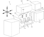
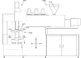
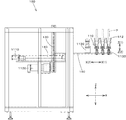
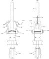
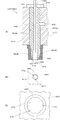
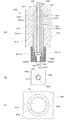
図1に本実施の形態に係るブロー成形装置10の全体を示す斜視図を、図2にブロー成
形装置10の全体を示す正面図を、図3にブロー成形装置10の全体を示す側面図を、図
4に図2におけるチャックユニット(捻回機構)100の拡大図を、それぞれ示す。
これらの図に示すように、このブロー成形装置10は、成形材料を加熱溶融させたパリ
ソンPをダイスヘッド220から下方へ押し出す押出ユニット(押し出し機構)200と
、対向させた合わせ面が離隔接近する2つに分割された金型310によりパリソンPを挟
み込んで金型310で挟み込まれたパリソンPに空気を送り込んでボトルBの形状にブロ
ー成形するブロー成形ユニット(ブロー成形機構)300と、押出ユニット200から押
し出されたパリソンPを把持して捻回するチャックユニット100とから構成される。
[overall structure]
FIG. 1 is a perspective view showing the whole
As shown in these drawings, in this
ここで、各ユニットの移動方向について説明する。
チャックユニット100においては、チャック110が、矢示X(1)、X(2)の水
平方向および矢示Z(1)、Z(2)の垂直方向へ移動可能に、ブロー成形ユニット30
0においては、金型310が、矢示X(3)、X(4)の水平方向および矢示Y(3)、
Y(4)の水平方向へ移動可能に、ブローヘッド330が、矢示Z(5)、Z(6)の垂
直方向へ移動可能に、それぞれ構成されている。
Here, the moving direction of each unit will be described.
In the
In 0, the
The
さらに、矢示を図示しないが、押出ユニット200におけるダイスヘッド220がZ方
向に移動可能で、カッターユニット240が水平面内を移動可能で、このカッターユニッ
ト240が作動する場合において、ダイスヘッド220が原点位置からZ方向の上方向へ
待避して、カッターユニット240が水平面内を移動して金型310に挟み込まれたパリ
ソンPを切断して、カッターユニット240の作動完了後にダイスヘッド220がZ方向
の下方向へ移動して原点位置へ復帰する。
Further, although the arrow is not shown, when the
このブロー成形装置10は、ブロー成形法により合成樹脂製の成形品(ここではボトル
B)を製造する成形装置であって、ダイスヘッド220を備え、ホッパー210から投入
された成形材料(限定されるものではないが多くの場合ポリエチレン(PE)、ポリプロ
ピレン(PP)、ポリスチレン(PS)等のチップ)を加熱溶融させた略中空円筒形状の
パリソンPを、その内筒面に1以上の縦溝H(図9(A)参照)を設けてダイスヘッド2
20から下方へ押し出す押出ユニット200と、押出ユニット200から押し出されたパ
リソンPを把持して捻回するチャックユニット100と、チャックユニット100により
捻回(ねじられた、ひねられた)パリソンPを金型310で挟み込んでブロー成形するブ
ロー成形ユニット300とを含んで構成される。このチャックユニット100は、押出ユ
ニット200から押し出されたパリソンPの端部(より詳しくは下端部)を把持するチャ
ック110と、パリソンPの押し出し方向に平行な軸を回転軸として、パリソンPの端部
を把持したチャック110を所定の角度分だけ回転するための回転サーボモータ1130
とを含んで構成される。
The
An
It is comprised including.
ここで、パリソンPに設けられる縦溝は、1以上の縦溝であればよい。また、ダイスと
コアとを収納したダイスヘッド220のコアにスリット(溝)を設けることにより、コア
に設けたスリットの部分に対応してパリソンPの内筒面の内面に凸部Gが形成され、コア
に設けたスリット以外の部分に対応してパリソンPの内筒面の内面に縦溝H(凹部)が形
成される。本発明においては、パリソンPの内面の凸部G(縦溝H以外)であってもパリ
ソンPの内面の縦溝Hであってもどちらかが1本以上あれば、ボトルの内周面に模様を形
成することができる。
Here, the longitudinal groove provided in the parison P may be one or more longitudinal grooves. Further, by providing a slit (groove) in the core of the
押出ユニット200は、このようなパリソンPを押し出すダイスヘッド220を備える
。このダイスヘッド220により、成形材料を加熱溶融させた略中空円筒形状の基体層の
内周面および外周面の少なくとも一方の周面から出っ張るように形成されるとともにパリ
ソンPの押し出し方向に沿って形成される1以上の凸部Gを備えた非円環断面形状のパリ
ソンPが、ダイスヘッド220から下方へ押し出される。
The
このようなダイスヘッド220としては、限定されるものではないが、一例として、図
10に示されるダイスヘッド400が採用される。
図10(A)に示すダイスヘッド400の一部断面図、図10(B)に示すダイスヘッ
ド400の一部下面図、図10(C)に示す図10(B)の部分拡大図を参照して、この
ダイスヘッド400について説明する。なお、図10においては、樹脂供給機構である、
押出機、プランジャ、アキュームレータ等については公知技術であるため描いていない。
The
Refer to the partial cross-sectional view of the
Since an extruder, a plunger, an accumulator, etc. are well-known techniques, they are not drawn.
ダイスヘッド400は、大略的には、中心軸側にマンドレル420が挿入されたダイス
ハウジング410とその下方に設けられたダイス(ダイ)480とで構成される。図10
に示すダイスヘッド400は、加熱溶融させた成形材料をダイスヘッド400の側方一箇
所より供給する、いわゆる、サイドフィード方式であって、樹脂供給機構により押圧され
た高温溶融状態の成形材料を、樹脂供給口430およびその樹脂供給口430に連結され
たマニホールド440を通して樹脂通路450Aおよび樹脂通路450Bに供給する。こ
のマニホールド440は、マンドレル420の周方向左右に途中まで分岐し通路断面積を
所定の割合で徐々に減少させつつ所定の曲率で押出方向に湾曲する半円断面状を備える。
このマニホールド440により、加熱溶融させた成形材料が、下流に位置する、環状の樹
脂通路450Aおよび環状の樹脂通路450Bに分配供給され、これらの樹脂通路450
Aおよび樹脂通路450Bにおいて均一な円環流動が形成される。
The
The
The manifold 440 distributes and supplies the molding material heated and melted to the
A uniform annular flow is formed in A and the
加熱溶融させた成形材料は、ダイスハウジング410とマンドレル420との間に設け
られた環状の樹脂通路450A、および、この樹脂通路450Aに接続される、ダイス4
80とマンドレル420との間に設けられた環状の樹脂通路450Bを通り、最下端の環
状空間通路460より吐出されてパリソンPを形成する。このダイスヘッド400の最下
端にはコア470が設けられ、コア470はマンドレル420を貫通したパリコン(パリ
ソンコントロール)用ロッド490に接続され、パリコンシリンダの作動により上下方向
僅かに進退され、パリソンPの肉厚を制御するために環状空間通路460の間隙(ギャッ
プ)を調整できるようになっている。
The molding material heated and melted is an
80 passes through an
本発明においては、このコア470にスリット(溝)472が設けられており、このス
リット472の部分に対応してパリソンPの内筒面の内面に、加飾部としての凸部G(図
9(A)参照)が形成される。
すなわち、環状空間通路460から吐出された成型材料がパリソンPの基体層を形成し
、スリット472から吐出された成型材料がパリソンPの加飾部である凸部Gを形成し、
全体として非円環断面形状のパリソンPが、ダイスヘッド220から下方へ押し出される
。
In the present invention, a slit (groove) 472 is provided in the
That is, the molding material discharged from the
A parison P having a non-annular cross-sectional shape as a whole is pushed downward from the
また、上述したチャック110は、パリソンPの外筒面をチャックするものとして説明
するが、パリソンPの内筒面を内側から広げるようにチャックしても、パリソンPの外筒
面および/または内筒面を吸引把持しても構わない。
このブロー成形装置10においては、押出ユニット200は、パリソンPを連続的に押
し出すために、チャックユニット100のチャック110がパリソンPの下端部を挟持し
ているときには、パリソンPの押し出し速度に対応させて、チャックユニット100の回
転軸方向に沿って下方(矢示Z(2)方向)へ移動する。
The
In the
このブロー成形装置10においては、押出ユニット200は、図9(A)に示す中空円
筒形状を維持してパリソンPを押し出すために、パリソンPの中空部にエアーを流通させ
ながらパリソンPを押し出す。そして、チャックユニット100のチャック110がパリ
ソンPの下端部を挟持しているときにこのエアーの流路が閉鎖されてしまうとエアーの逃
げ場がなくなりパリソンPが膨張してしまうので、チャック110は、このエアーの流通
を阻害しないように、パリソンPの下端部を挟持する。
In the
このブロー成形装置10においては、ブロー成形ユニット300は、チャック110に
よる挟持が解除されたパリソンPをブロー成形するのであるが、この場合において、チャ
ック110による挟持が解除されたパリソンが金型310で挟み込まれるまでの間は捻り
力がパリソンPに作用していないので(パリソンPの上端はダイスヘッド220で把持さ
れているが下端は自由端となってしまうので)その捻れが戻ってしまう場合がある。この
ような場合にそのままブロー成形してしまうと所望の模様をボトルB内面に施すことがで
きない。このため、チャックユニット100でパリソンPを回転させる所定の角度は、ブ
ロー成形後の成形品における捻り角度に、チャック110の挟持が解除されたパリソンP
が金型310で挟み込まれるまでに戻る角度に対応させた角度分だけ余分に加えた角度と
している。
In this
Is an angle that is added by an angle corresponding to the angle that is returned until it is sandwiched by the
なお、ここでは、チャック110による挟持を解除してパリソンPをブロー成形すると
して説明したが、本発明はチャック110による挟持を解除しないでパリソンPをブロー
成形するものであっても構わない。チャック110によるパリソンPの外周面の挟持を解
除してパリソンPをブロー成形する場合には以下のような態様も考えられる。
チャック110がパリソンPの下端部の外筒面を一対のチャック110で挟持して、そ
の挟持を解除すると、外気温にパリソンPが触れておりパリソンPの温度が低下している
こともあって元の円筒形状に戻らないで、チャック110で挟持していたパリソンPの下
端部は変形して略平らな平面(図6(D)参照)が形成されてしまう。この場合において
、金型310が対向させた合わせ面が離隔接近する2つに分割された金型である場合に、
パリソンPの変形した下端部の略平らな平面が、合わせ面を含む平面と略平行でないと、
金型310が接近して合わせ面が圧接されたときに略平らな平面が抵抗になる等の理由で
ボトルBの底面に乱れた模様を形成してしまう場合がある。このため、チャック110が
解除されたパリソンPにおいてチャック110により挟持されたことにより形成された略
平らな平面が、金型310の合わせ面を含む平面と略平行になる位置で、パリソンPの下
端部を挟持したチャック110の回転を停止するようにしている(図6(D)、図6(E
)参照)。
Here, the description has been made assuming that the parison P is blow-molded by releasing the pinching by the
When the
If the substantially flat plane of the deformed lower end of the parison P is not substantially parallel to the plane including the mating surface,
When the
)reference).
このような特徴を備えた本実施の形態に係るブロー成形装置10について、チャックユ
ニット100を中心に、上述した図1〜図4に図5〜図9を加えてさらに詳しく説明する
。なお、図5および図6はチャックユニット100の動作を説明するための図であって、
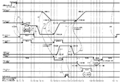
図7はブロー成形装置10の制御ブロック図であって、図8はブロー成形装置10の動作
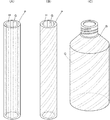
を説明するためのタイミングチャートであって、図9はブロー成形装置10によりパリソ
ンPから製造されるボトルBを説明するための斜視図である。
The
FIG. 7 is a control block diagram of the
[各部構成]
・チャックユニット
このチャックユニット100は、一般的なダイレクトブロー成形装置が備えないで、本
発明に係るブロー成形装置10が独自に備える特徴的なユニットである。
チャックユニット100は、パリソンPの下端部を挟持する一対の爪112から構成さ
れるチャック110と、そのチャック110を回転させる回転サーボモータ1130等の
回転機構と、そのチャック110を水平移動させる水平移動サーボモータ1110および
水平スライドベース140等の水平移動機構と、そのチャック110を上下移動させる上
下移動サーボモータ1120および垂直スライドベース130等の水平移動機構と、その
チャック110を開閉するチャックエアシリンダ1140とから構成される。
[Each component configuration]
-Chuck unit The
The
図5に示すようにチャック110は、パリソンPの下端部を挟持する一対の爪112を
備え、チャックエアシリンダ1140を作動させることにより矢示C(1)方向へ閉じた
り矢示C(2)方向へ開いたりすることができる。この爪112はたとえばアルミ製であ
って、この爪112において少なくともパリソンPが当接する部分はたとえばフッ素コー
ティングしてあり、爪112を矢示C(1)方向へ閉じてパリソンPを挟持した後に爪1
12を矢示C(2)方向へ開くと、爪112からパリソンPが容易に離隔して(離隔しな
いと次工程に進むことができない)、このブロー成形装置10の動作を妨げることがない
。
As shown in FIG. 5, the
When 12 is opened in the direction indicated by arrow C (2), the parison P is easily separated from the claw 112 (if it is not separated, it cannot proceed to the next step), and the operation of the
ここで、図5(B)に示すように、チャックユニット100のチャック110がパリソ
ンPの下端部を挟持するために矢示C(2)方向へ爪112が閉じた場合には、爪112
どうしが当接する前にそれぞれの爪112の根元に設けられた規制部材(ここではボルト
114とそのボルト114に螺合する爪112の根元部分の部材の貫通穴に切られた雌ネ
ジとで構成)が当接する。このため、矢示C(2)方向へ爪112が閉じた場合にも、パ
リソンPの内筒部分には、押出ユニット200がパリソンPの中空円筒形状を維持するた
めにパリソンPの中空部に流通させているエアーの流路の間隔Dを維持することができる
。そして、パリソンPの形状によりこの間隔Dを変更する必要が発生した場合であっても
、規制部材のボルト114の位置を調整することにより容易に間隔Dを変更することがで
きる。
Here, as shown in FIG. 5B, when the
A restricting member provided at the base of each
チャック110を回転させる回転機構は、3つのチャック110を1台の回転サーボモ
ータ1130で回転させるために、回転サーボモータ1130から減速器、ギヤおよびチ
ェーン等の動力伝達部材で伝達された回転力を受けてチャック110の一対の爪112を
回転させるギヤボックス1132を備える。
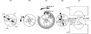
次に、図6を参照して、この回転機構の回転角度と回転終了位置とについて説明する。
ここでは、目標回転角度(ブロー成形後のボトルBにおける捻り角度)を300°として
いる。上述したように、ブロー成形ユニット300は、チャック110による挟持が解除
されたパリソンPをブロー成形する。この場合において、パリソンPの大きさ等の形状、
回転角度、成形材料の粘性等の諸元によっては、チャック110による挟持が解除された
パリソンが金型310で挟み込まれるまでの間(後述する図8のタイミングチャートにお
ける時刻T(8)〜時刻T(12)の間)に、捻れが戻ってしまう場合がある。このよう
な場合に対応して、チャックユニット100でパリソンPを回転させる所定の角度は、ブ
ロー成形後の成形品における捻り角度(図6では目標回転角300°)に、チャック11
0の挟持が解除されたパリソンPが金型310で挟み込まれるまでに戻る角度(図6では
過回転角15°)に対応させた角度分だけ余分に加えた角度(図6では回転角315°)
としている。
The rotation mechanism that rotates the
Next, the rotation angle and rotation end position of the rotation mechanism will be described with reference to FIG.
Here, the target rotation angle (twist angle in the bottle B after blow molding) is set to 300 °. As described above, the
Depending on the specifications such as the rotation angle and the viscosity of the molding material, the period until the parison released from the
An extra angle (an angle of rotation of 315 ° in FIG. 6) corresponding to an angle corresponding to the angle at which the parison P released from being pinched by 0 is returned by the mold 310 (an over rotation angle of 15 ° in FIG. 6). )
It is said.
このため、図6(A)に示す爪112の位置(回転開始角)で爪112をC(1)方向
へ閉じて図6(B)に示すようにパリソンPを挟持して、パリソンPの押し出し速度に対
応(同期)させてチャック110を矢示Z(2)方向へ下降させながら図6(B)の矢示
の方向へ回転させる。図6(B)に示すようにパリソンPを挟持してパリソンPを所定の
長さ分だけ押し出す時間だけ経過すると図6(C)に示す爪112の位置(回転終了角)
になるように回転速度を設定する。すなわち、図6(B)に示す状態から図6(C)に示
す状態になるまで(パリソンPを所定の長さ分だけ押し出す時間まで)、チャック110
を矢示Z(2)方向へパリソンPの押し出し速度に対応(同期)させて下降させながら、
図6(B)の矢示の方向へ回転させ、図6(C)の回転角(315°)だけ回転させてい
る。
Therefore, the
Set the rotation speed so that That is, until the state shown in FIG. 6B is changed to the state shown in FIG. 6C (until the time when the parison P is pushed by a predetermined length), the
, In the direction of arrow Z (2) corresponding to (synchronized) with the pushing speed of the parison P,
It is rotated in the direction indicated by the arrow in FIG. 6B, and is rotated by the rotation angle (315 °) in FIG.
そして、図6(C)に示す爪112の位置(回転角315°分だけ回転した回転終了角
の位置)で、爪112をC(2)方向へ開いて図6(D)に示すようにパリソンPの挟持
を解除する。
上述したように、チャック110がパリソンPの下端部の外筒面を一対の爪112で挟
持して、その挟持を解除すると、外気温にパリソンPが触れておりパリソンPの温度が低
下していることもあって元の円筒形状に戻らないで、チャック110で挟持していたパリ
ソンPの下端部は変形して略平らな平面(ただし図6(D)に示すようにこの場合でも中
空部は潰れていない)が形成され円筒形状には戻らない。特に、パリソンPの成形材料の
粘性等の諸元およびこのブロー成形装置10の周囲温度等によっては大きく変形して略平
らな平面が形成されてしまい、元の円筒形状に戻らない。図6(C)に示す状態から爪1
12による挟持を解除すると、パリソンPは金型310で挟み込まれるまでに戻る過回転
角に対応する角度まで捻れが戻る。
Then, at the position of the
As described above, when the
When the pinching by 12 is released, the parison P returns to the angle corresponding to the over-rotation angle that is returned until it is pinched by the
そして、図6(D)および図6(E)に示すように、この捻れが戻った状態における略
平らな平面が、金型310の合わせ面を含む平面と略平行になる位置で、チャック110
の回転を停止するようにしている。
すなわち、チャックユニット100によるパリソンPの捻回(回転)については、
(1)その回転角度(の絶対値)は、ブロー成形後の成形品における捻り角度(図6で
は目標回転角300°)に、チャック110の挟持が解除されたパリソンPが金型310
で挟み込まれるまでに戻る角度(図6では過回転角15°)に対応させた角度分だけ余分
に加えた角度(図6では回転角315°)であって、
(2)その回転終了角度は、パリソンPが金型310で挟み込まれるまでに捻れが戻っ
たときに(図6では過回転角15°分が戻る)のパリソンPの下端部の略平らな平面が金
型310の合わせ面を含む平面と略平行になる位置である、
ように、パリソンPの大きさ等の形状、回転角度、成形材料の粘性等の諸元に基づいて
(場合によっては試行錯誤して)、チャックユニット100の回転サーボモータ1130
の制御パラメータ(回転開始角、回転終了角、回転時間(=下降時間)、回転開始タイミ
ング、回転終了タイミング等)が適宜設定される。
Then, as shown in FIGS. 6D and 6E, the
The rotation is stopped.
That is, about the twist (rotation) of the parison P by the
(1) The rotation angle (absolute value) is equal to the twist angle (
Is an angle (rotation angle of 315 ° in FIG. 6) that is added by an angle corresponding to the angle that returns until it is sandwiched by (over rotation angle of 15 ° in FIG. 6),
(2) The rotation end angle is a substantially flat plane at the lower end of the parison P when the twist is restored before the parison P is sandwiched between the molds 310 (in FIG. 6, the rotation angle is returned by 15 °). Is a position substantially parallel to a plane including the mating surface of the
As described above, the
These control parameters (rotation start angle, rotation end angle, rotation time (= fall time), rotation start timing, rotation end timing, etc.) are appropriately set.
なお、回転方向は図6に示す反時計回りに限定されるものではない。
・押出ユニット
この押出ユニット200は、一般的なダイレクトブロー成形装置に好適に適用されるユ
ニットであって、成形材料を加熱溶融させてパリソンPを中空円筒形状を維持して押し出
す。上述したように、特徴的であるのは、成形品であるボトルBの内面に模様を施すため
に、ダイスとコアとを収納したダイスヘッド220のコアに1以上のスリット(溝)を設
けている点である。このようにコアにスリットを設けることにより、コアに設けたスリッ
トの部分に対応してパリソンPの内筒面の内面に1以上の凸部Gが形成され、コアに設け
たスリット以外の部分に対応してパリソンPの内筒面の内面に1以上の縦溝H(凹部)が
形成される。
The rotation direction is not limited to the counterclockwise direction shown in FIG.
-Extrusion unit This
なお、この押出ユニット200は、上述したように、カッターユニット240が作動す
る場合にダイスヘッド220がZ方向に移動して待避する以外は、基本的に移動しない。
・ブロー成形ユニット
このブロー成形ユニット300は、一般的なダイレクトブロー成形装置に好適に適用さ
れるユニットであって、成形材料を加熱溶融させたパリソンPを金型310で挟み込んで
、金型310に挟み込んだパリソンPの内部に空気を吹き込んで中空品を成形する。この
金型310は、スライドベース320上を金型水平移動サーボモータ1310により矢示
X(3)、X(4)方向へ移動する。さらに、この金型310は、矢示Y(3)、矢示Y
(4)方向への開閉が可能であって、この開閉には油圧等が用いられる。
As described above, the
Blow molding unit This
(4) Opening and closing in the direction is possible, and hydraulic pressure or the like is used for opening and closing.
この金型310は、矢示Y(4)方向へ開いた状態でパリソンPの挟み込み位置(受取
位置)まで矢示X(4)方向へ移動して、パリソンPを挟み込んだ状態で矢示Y(3)方
向へ閉じて(このとき金型310が矢示X(3)方向へ移動する前にカッターユニット2
40が作動)、矢示Y(3)方向へ閉じた状態でパリソンPのブロー位置(成形位置)ま
で矢示X(3)方向へ移動する。ブロー成形が終わると、ブロー成形後のボトルBを取り
出すために金型310は矢示Y(3)方向へ開く。
The
40 is activated), and moves in the direction of arrow X (3) to the blow position (molding position) of parison P in the closed state in the direction of arrow Y (3). When blow molding is finished, the
パリソンPを挟み込んだ金型310が矢示X(3)方向へ移動してブロー位置(成形位
置)へ到着すると、ブローヘッド330が矢示Z(6)方向へ下降して、ブローヘッド3
30の先端がパリソンPの上端部へ挿入されて、金型310に挟み込まれたパリソンPに
エアが吹き込まれてブロー成形される。ブロー成形が終わると、金型310は矢示Y(3
)方向へ開き、その先端がボトルBの上端部へ挿入されたブローヘッド330が矢示Z(
5)方向へ上昇する。このとき、ブローヘッド330の先端の外周がボトルBの上端の内
周(より詳しくはバリ部分の内周)に付着して保持されている。このため、ブローヘッド
330の上昇とともにボトルBは矢示Z(5)方向へ上昇し、その途中で上下方向に移動
しない固定具340にボトルBの肩部分が当接するが(ボトルBはそれ以上上昇できない
)、ブローヘッド330はさらに上昇を続けるのでボトルBは自由落下して、ブローヘッ
ド330からボトルBとが離脱される。
When the
The tip of 30 is inserted into the upper end of the parison P, and air is blown into the parison P sandwiched between the
) Direction, and the
5) Ascend in the direction. At this time, the outer periphery of the tip of the
[制御ブロック]
このような構成を備えたブロー成形装置10は、演算ユニット1000により制御され
る。演算ユニット1000を含めて後述する各種計器が、制御盤または操作盤の内部に収
められて構成される。制御盤または操作盤の盤面には、タッチパネル(タッチパネル自体
に加えてたとえばタッチパネル入力部1060およびタッチパネル表示ドライバ1090
により構成)および緊急停止等の押釦スイッチ1070が設けられたり、パトライト(登
録商標)等の表示灯1080が設けられたりする。
[Control block]
The
And a
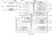
さらに具体的に、図7を参照して、このブロー成形装置10の制御ブロックを説明する
。なお、図7に示す制御ブロック図においては、たとえばサーボモータ(モータ駆動ドラ
イバ等も含む)等を備える態様を示しているが、実際にはこのようなサーボモータを備え
なくても、このブロー成形装置10が所望の動作を実現できるように別の態様で構成され
ていれば構わない。このような別の態様としては、モータではなくエア機器を電磁弁によ
り作動させて所望の動作を実現する態様が考えられる。
More specifically, the control block of the
図7に示すように、このブロー成形装置10の制御ブロックは、予め記憶されたプログ
ラムおよびパラメータに従って、各種の入力機器から入力された入力信号(センサによる
パリソン検出信号等)を受けて演算処理を実行し各種の出力機器へ各種の出力信号(制御
信号)を出力するCPU1010、メモリ1020、タイマ1030およびカウンタ10
40を含む演算ユニット1000と、この演算ユニット1000に接続された各種の入力
機器ならびに各種の出力機器とで構成される。
As shown in FIG. 7, the control block of this
The
出力機器としては、一例として、チャックユニット100の水平移動サーボモータ11
10、上下移動サーボモータ1120、回転サーボモータ1130、チャックエアシリン
ダ1140があり、押出ユニット200の押出ユニットコントローラ1200があり、ブ
ロー成形ユニット300の金型水平移動サーボモータ1310、金型開閉(油圧)機器1
320、ブローヘッド上下移動サーボモータ1330、エアブロー機器1340、カッタ
ー水平面内移動エア機器1350、およびカッター温度コントローラ1360がある。
As an output device, for example, the horizontal
10, vertical
320, a blow head up-and-down moving
なお、図7における制御ブロックにおいては、演算ユニット1000が直接サーボモー
タを制御するように記載されているが、これに限定されるものではなく、一般的にはサー
ボコントローラを介して演算ユニット1000がサーボモータを制御する。また、図7に
示した押出ユニットコントローラ1200は、一般的なブロー成形装置の押出ユニットを
制御するものと同じか同等である。
In the control block in FIG. 7, it is described that the
押出ユニット200からパリソンPが安定的に押し出されている状態で開始指令信号を
受信したCPU1010は、たとえば、以下のように、このブロー成形装置10を制御す
る。この場合の説明においては、主として図8のタイミングチャートを参照する。なお、
このタイミングチャートの横軸である時間軸は適宜設定したものであって、この時間軸に
限定されるものではなく(特に時間間隔の相対値)、T(0)〜T(24)に現実の時間
を代入することにより現実の動作を表すタイミングチャートとなる。すなわち、たとえば
、このタイミングチャートにおけるディレー時間は大きく表されており、これを現実のデ
ィレー時間(100msec程度)とすると、現実のタイミングチャートは図8のタイミ
ングチャートとは異なるものとなることを意味する。
The
The time axis, which is the horizontal axis of this timing chart, is set as appropriate, and is not limited to this time axis (particularly the relative value of the time interval). By substituting time, it becomes a timing chart showing an actual operation. That is, for example, the delay time in this timing chart is greatly represented, and if this is the actual delay time (about 100 msec), it means that the actual timing chart is different from the timing chart of FIG. .
<ステップS(1)>
押出ユニット200からパリソンPが安定的に押し出されている状態で開始指令(作業
者の動作に基づく開始指令)を受信したCPU1010は、ダイスヘッド220から押し
出されて下降するパリソンPを検出したセンサからの検出信号を受信する。
<ステップS(2)>
パリソンPを検出したセンサの位置からチャックユニット100のチャック110(よ
り詳しくは爪112)により挟持できる位置までパリソンPが下降するまでの遅延時間が
経過すると、CPU1010は、チャックユニット100のチャックエアシリンダ114
0に矢示C(2)方向に開いていた爪112を矢示C(1)方向に閉じるように指示する
。
<Step S (1)>
The
<Step S (2)>
When a delay time elapses until the parison P descends from the position of the sensor that detects the parison P to a position where it can be clamped by the chuck 110 (more specifically, the claw 112) of the
0 is instructed to close
<ステップS(3)>
爪112が矢示C(1)方向に閉じたことを検出したCPU1010は、チャックユニ
ット100の上下移動サーボモータ1120に把持位置から開放位置へ向けてパリソンP
の押し出し速度に対応させて(同期させて)矢示Z(2)方向へ下降するように指示する
ともに、チャックユニット100の回転サーボモータ1130に回転開始位置から回転終
了位置へ向けて回転するように指示する。
<Step S (3)>
The
Is instructed to descend in the direction of the arrow Z (2) in accordance with (synchronized) with the extrusion speed of the motor, and the
<ステップS(4)>
チャックユニット100の爪112が矢示Z(2)方向へ下降して開放位置まで到達し
たこと、および、チャックユニット100の回転機構が回転終了角度まで回転したことを
検出したCPU1010は、チャックユニット100の上下移動サーボモータ1120お
よび回転サーボモータへ停止するように指示するともに、チャックユニット100のチャ
ックエアシリンダ1140に矢示C(1)方向に閉じていた爪112を矢示C(2)方向
に開くように指示する。
<Step S (4)>
The
<ステップS(5)>
爪112が矢示C(2)方向に開いたことを検出したCPU1010は、チャックユニ
ット100の上下移動サーボモータ1120に開放位置から下待避位置まで矢示Z(2)
方向へ下降するように指示する。
<ステップS(6)>
チャックユニット100の爪112が矢示Z(2)方向へ下降して下待避位置まで到達
したことを検出したCPU1010は、チャックユニット100の上下移動サーボモータ
1120へ停止するように指示するともに、チャックユニット100の水平移動サーボモ
ータ1110に作動位置から左待避位置まで矢示X(2)方向へ移動するように指示する
。
<Step S (5)>
The
Instruct to descend in the direction.
<Step S (6)>
The
<ステップS(7)〜S(9)>
チャックユニット100の爪112が矢示X(2)方向へ移動して左待避位置まで到達
したことを検出したCPU1010は、チャックユニット100の水平移動サーボモータ
1110へ停止するように指示するともに、ブロー成形ユニット300の金型開閉(油圧
)機器1320に金型310を互いに離隔するように矢示Y(4)方向へ移動するように
指示する(S(7))。このS(7)で出力される信号は、チャックユニット100から
ブロー成形ユニット300へのインターロック信号となり、このインターロック信号を受
けたブロー成形ユニット300が水平方向への移動動作を開始できるようになる。
<Steps S (7) to S (9)>
The
また、このタイミング、すなわち、チャックユニット100の爪112が矢示X(2)
方向へ移動して左待避位置まで到達したことを検出したCPU1010は、チャックユニ
ット100の回転サーボモータ1130に回転終了位置から回転開始位置へ向けて逆回転
するように指示するとともに(S(8))、チャックユニット100の上下移動サーボモ
ータ1120に下待避位置から把持位置まで矢示Z(1)方向へ上昇するように指示する
(S(9))。
At this timing, that is, the
The
<ステップS(10)〜S(11)>
チャックユニット100の爪112が矢示Z(1)方向へ上昇して把持位置まで到達し
たことを検出したCPU1010は、チャックユニット100の上下移動サーボモータ1
120へ停止するように指示するとともに(S(10))、S(16)にて受信するブロ
ー成形ユニット300からのインターロック信号の受信を待つ。
<Steps S (10) to S (11)>
The
120 is instructed to stop (S (10)), and waits for reception of an interlock signal from the
逆回転が完了して爪112が回転開始位置まで到達したことを検出したCPU1010
は回転サーボモータ1130に停止するように指示するとともに(S(11))、S(1
6)にて受信するブロー成形ユニット300からのインターロック信号の受信を待つ。こ
のS(16)で出力される信号は、ブロー成形ユニット300からチャックユニット10
0へのインターロック信号であって、この信号を受けたチャックユニット100が水平方
向への移動動作を開始できるようになる。
Instructs the
6) Waiting for reception of the interlock signal from the
This is an interlock signal to 0, and the
<ステップS(12)>
ブロー成形ユニット300の金型310が互いに離隔したことを検出したCPU101
0は、金型水平移動サーボモータ1310に成形位置から受取位置まで矢示X(4)方向
へ移動するように指示する。
<ステップS(13)>
ブロー成形ユニット300の金型310が矢示X(4)方向へ移動して受取位置まで到
達したことを検出したCPU1010は、金型水平移動サーボモータ1310へ停止する
ように指示するともに、金型開閉(油圧)機器1320に金型310を互いに接近するよ
うに矢示Y(3)方向へ移動するように指示する。
<Step S (12)>
CPU101 which detected that
0 instructs the mold horizontal
<Step S (13)>
The
<ステップS(14)>
ブロー成形ユニット300の金型310が互いに接近して合わせ面が当接したことを検
出したCPU1010は、カッターユニット240へ作動指令を出力する。作動指令を受
信すると、押出ユニット200のダイスヘッド220が原点位置からZ方向の上方向へ待
避して、カッターユニット240のカッター水平面内移動エア機器1350により線状の
ヒートカッターが水平面内を移動して金型310に挟み込まれたパリソンPを切断して、
カッターユニット240の作動完了後にダイスヘッド220がZ方向の下方向へ移動して
原点位置へ復帰する。
<Step S (14)>
CPU1010 which detected that the metal mold | die 310 of the
After the operation of the
<ステップS(15)>
カッターユニット240の作動が完了したことを検出したCPU1010は、金型水平
移動サーボモータ1310に受取位置から成形位置まで矢示X(3)方向へ移動するよう
に指示する。
<ステップS(16)〜S(17)>
ブロー成形ユニット300の金型310が矢示X(3)方向へ移動して成形位置まで到
達したことを検出したCPU1010は、金型水平移動サーボモータ1310へ停止する
ように指示するともに、チャックユニット100の水平移動サーボモータ1110に左待
避位置から作動位置まで矢示X(1)方向へ移動するように指示し(S(16)、ブロー
成形ユニット300のブローヘッド上下移動サーボモータ1330に上待避位置からブロ
ー位置まで矢示Z(6)方向へ下降するように指示する(S(17))。
<Step S (15)>
The
<Steps S (16) to S (17)>
The
なお、S(16)の指示によりチャックユニット100のチャック110が矢示X(1
)方向へ移動して、チャックユニット100のチャック110が作動位置まで到達したこ
とを検出したCPU1010は水平移動サーボモータ1110に停止するように指示する
。
<ステップS(18)>
ブロー成形ユニット300のブローヘッド330が矢示Z(6)方向へ下降してブロー
位置まで到達したことを検出したCPU1010は、ブローヘッド上下移動サーボモータ
1330へ停止するように指示するともに、ブロー成形ユニット300のエアブロー機器
1340にブローエアをブローヘッド330からパリソンPの内部へ吹き出すように指示
する。
Note that the
The
<Step S (18)>
The
<ステップS(19)>
ブロー成形時間が経過したことを検出したCPU1010は、ブロー成形ユニット30
0のエアブロー機器1340へブローエアの吐出を停止するように指示するともに、ブロ
ー成形ユニット300の金型開閉(油圧)機器1320に金型310を互いに離隔するよ
うに矢示Y(4)方向へ移動するように指示する。
<Step S (19)>
The
Instruct the zero
<ステップS(20)>
ブロー成形ユニット300の金型310が互いに離隔したことを検出したCPU101
0は、ブロー成形ユニット300のブローヘッド上下移動サーボモータ1330にブロー
ヘッド330をブロー位置から上待避位置まで矢示Z(5)方向へ上昇するように指示す
る。
<Step S (20)>
CPU101 which detected that
0 instructs the blow head vertical
<ステップS(21)>
ブローヘッド330の上昇中に、ブローヘッド330の上昇とともにボトルBは矢示Z
(5)へ上昇し、その途中で上下方向に移動しない固定具340に肩部分が当接して自由
落下したボトルBを検出したCPU1010は、金型開閉(油圧)機器1320に金型3
10を互いに接近するように矢示Y(3)方向へ移動するように指示する。
<Step S (21)>
While the
The
10 is instructed to move in the direction of arrow Y (3) so as to approach each other.
[動作]
以上のような構造(プログラム構造を含む)を備えたブロー成形装置10の動作を説明
する。動作の説明においても、主として図8のタイミングチャートを参照する。
作業者は、押出ユニット200から図9(A)に示すパリソンPが安定的に押し出され
ている状態で、ブロー成形装置10にブロー成形を開始させる(開始指令信号を与える)
。
[Operation]
Operation | movement of the
An operator causes the
.
時刻T(0)において、ダイスヘッド220から押し出されて下降するパリソンPをセ
ンサが検出する(S(1))。このときのパリソンPは図9(A)に示す状態である。
時刻T(0)から時刻T(1)まで遅延時間が経過している間に、チャック110(よ
り詳しくは爪112)により挟持できる位置までパリソンPが下降して、時刻T(1)に
おいて矢示C(2)方向に開いていたチャックユニット100のチャック110の爪11
2が矢示C(1)方向に閉じる。これにより、図5(A)に示す状態から図5(B)に示
す状態へ遷移して、爪112がパリソンPを挟持する。
At time T (0), the sensor detects the parison P that is pushed out of the
While the delay time has elapsed from time T (0) to time T (1), the parison P descends to a position where it can be clamped by the chuck 110 (more specifically, the claw 112), and at time T (1)
2 closes in the direction of arrow C (1). Thereby, the state shown in FIG. 5 (A) is changed to the state shown in FIG. 5 (B), and the
時刻T(2)から時刻T(3)までの時間において、チャックユニット100のチャッ
ク110の爪112が閉じてパリソンPの下端部を挟持した状態で、パリソンPの押出速
度に対応(同期)させてチャック110が下降しつつ回転する。このとき、図6(A)に
示す状態から、図6(B)に示す状態を経て、図6(C)に示す状態へ遷移する。
時刻T(4)において、チャックユニット100のチャック110の爪112が開いて
パリソンPの挟持が開放される。図6(C)に示す状態から図6(D)に示す状態へ遷移
する。なお、チャックユニット100のチャック110の爪112が開いてパリソンPの
挟持が開放する時刻T(4)から、ブロー成形ユニット300の金型310がパリソンP
を挟み込む時刻T(12)までの間、パリソンPの下端部は挟持されないために、図6(
C)に示す過回転角15°分だけ捻れが戻る。このときのパリソンPは図9(B)に示す
状態である。
During the period from time T (2) to time T (3), the
At time T (4), the
Since the lower end of the parison P is not sandwiched until time T (12) when the segment is sandwiched, FIG.
The twist returns by the over-rotation angle of 15 ° shown in C). The parison P at this time is in the state shown in FIG.
時刻T(5)から時刻T(6)までの時間において、チャックユニット100のチャッ
ク110が開放位置から下待避位置まで下降する。これにより、チャック110とパリソ
ンPとが完全に離隔して、チャックユニット100のチャック110の水平移動が可能と
なる。
時刻T(7)から時刻T(8)までの時間において、チャックユニット100のチャッ
ク110が作動位置から左待避位置まで移動する。これにより、チャックユニット100
が押出ユニット200から完全に待避して、ブロー成形ユニット300の金型310の水
平移動が可能となる。
During the time from time T (5) to time T (6), the
In a time period from time T (7) to time T (8), the
Is completely retracted from the
時刻T(9)において、閉じていた金型310が開いて、時刻T(10)から時刻T(
11)までの時間において、ブロー成形ユニット300の金型310が成形位置から受取
位置まで移動する。これにより、ブロー成形ユニット300の金型310が押出ユニット
200のダイスヘッド220から垂下した(ぶら下がった)状態のパリソンPを受け取る
ことが可能となる。このとき、パリソンPとブロー成形ユニット300の金型310とは
、図6(D)および図6(E)に示す状態である。
At time T (9), the
11), the
時刻T(12)において、開いていた金型310が閉じて、時刻T(13)から時刻T
(14)までの時間において、カッターユニット240が作動する。このとき、押出ユニ
ット200のダイスヘッド220が原点位置からZ方向の上方向へ待避して、線状のヒー
トカッターが水平面内を移動して金型310に挟み込まれたパリソンPを切断して、カッ
ターユニット240の作動完了後にダイスヘッド220がZ方向の下方向へ移動して原点
位置へ復帰する。これにより、金型310に挟まれたパリソンPと押出ユニット200の
ダイスヘッド220から連続的に押し出されているパリソンPとが分離されて、ブロー成
形ユニット300の金型310の水平移動が可能となる。
At time T (12), the opened
During the time up to (14), the
時刻T(15)から時刻T(16)までの時間において、ブロー成形ユニット300の
金型310が成形位置からブロー位置まで移動する。これにより、ブロー成形ユニット3
00の金型310に挟み込まれたパリソンPにブロー成形ユニット300のブローヘッド
330が下降してブローヘッド330の先端のノズルをパリソンPに挿入することが可能
となる。
During a period from time T (15) to time T (16), the
The
時刻T(17)から時刻T(18)までの時間において、ブロー成形ユニット300の
ブローヘッド330が上待避位置からブロー位置まで下降して、ブローヘッド330の先
端のノズルをパリソンPに挿入される。
時刻T(19)から時刻T(20)までの時間(ブロー成形時間)において、パリソン
Pに挿入されたブローヘッド330の先端のノズルからパリソンPの内部へブローエアが
吹き出されてパリソンPが膨張する。
During a period from time T (17) to time T (18), the
During time (blow molding time) from time T (19) to time T (20), blow air is blown out from the nozzle at the tip of the
時刻T(21)において、閉じていた金型310が開いて、時刻T(22)から時刻T
(23)までの時間において、押出ユニット200のブローヘッド330がブロー位置か
ら上待避位置まで上昇する。このブローヘッド330の上昇中に、ボトルBが自由落下す
ると、時刻T(24)において、開いていた金型310が閉じて、1サイクルタイムが完
了して、全ての機器の状態がT(0)と同じ状態になる。
At time T (21), the
During the time up to (23), the
この状態で作業者が、このブロー成形装置10により製造されたボトルBを取り出す。
このときのボトルBは図9(C)に示す状態である。
以上のようにして、本実施の形態に係るブロー成形装置10によると、ブロー成形方法
を実現できて、簡易な製造装置で安価な製造コストで、側面の内面にスパイラル模様が施
されたブロー成形品を製造することができる。
<変形例>
以下において、本発明の変形例に係るブロー成形装置について説明する。本変形例に係
るブロー成形装置は、上述したブロー成形装置10のダイスヘッド220(詳細には図1
0に示したダイスヘッド400)とは異なるダイスヘッド500を備える点を除いて、上
述したブロー成形装置10と同じ構成で同じ動作を実現する。このため、同じ構成および
同じ動作についての説明については、ここでは繰り返さない。
In this state, the operator takes out the bottle B manufactured by the
The bottle B at this time is in the state shown in FIG.
As described above, according to the
<Modification>
Hereinafter, a blow molding apparatus according to a modification of the present invention will be described. The blow molding apparatus according to this modification is a
The same operation as that of the
本変形例に係るブロー成形装置が備えるダイスヘッド500により、第1の成形材料を
加熱溶融させた略中空円筒形状の基体層の内周面および外周面の少なくとも一方の周面か
ら出っ張るように形成されるとともにパリソンPの押し出し方向に沿って形成される1以
上の凸部Gを備えた非円環断面形状のパリソンPが、ダイスヘッド500から下方へ押し
出される。特徴的であるのは、上述したブロー成形装置10とは異なり、この凸部Gは、
基体層を形成する第1の成形材料とはダイスヘッド500内の樹脂通路が異なる第2の成
形材料で形成されている点である。
Formed so as to protrude from at least one of the inner peripheral surface and the outer peripheral surface of the substantially hollow cylindrical base layer in which the first molding material is heated and melted by the
The first molding material forming the base layer is that the resin passage in the
さらに詳しくは、このダイスヘッド500は、ハウジングおよび2以上のマンドレルに
より構成される、加熱溶融された第1の成形材料が流れる第1の樹脂通路と、加熱溶融さ
れた第2の成形材料が流れる第2の樹脂通路とを含み、第1の樹脂通路と第2の樹脂通路
とはダイスヘッド500の内部で合流しない。なお、本変形例においては、成形材料の種
類が2種類であるのでマンドレルは2個であるとするが、成形材料の種類数に対応させて
マンドレルの個数が適宜変更される。
More specifically, the
ここで、第1の成形材料と第2の成形材料とは同じであっても異なっていても構わない
が、第1の成形材料と第2の成形材料とを異ならせて第1の成形材料の色彩と第2の成形
材料の色彩とが異なるようにすると、本変形例に係るブロー成形装置により成形されるボ
トルBの意匠上特に好ましい。なお、第1の成形材料と第2の成形材料とを異ならせる場
合には、第1の成形材料と第2の成形材料との接触面に接着層を構成することも好ましい
。
Here, the first molding material and the second molding material may be the same or different, but the first molding material and the second molding material are different from each other. It is particularly preferable in terms of the design of the bottle B molded by the blow molding apparatus according to this modification to make the color of the second molding material different from the color of the second molding material. In the case where the first molding material and the second molding material are different, it is also preferable to form an adhesive layer on the contact surface between the first molding material and the second molding material.
このようなダイスヘッド500としては、限定されるものではないが、一例として、図
11に示されるダイスヘッド500が採用される。
図11(A)に示すダイスヘッド500の一部断面図、図11(B)に示すダイスヘッ
ド500の一部下面図、図11(C)に示す図11(B)の部分拡大図を参照して、この
ダイスヘッド500について説明する。なお、図11においては、図10と同様に、樹脂
供給機構である、押出機、プランジャ、アキュームレータ等については公知技術であるた
め描いていない。
Such a
11A is a partial cross-sectional view of the
ダイスヘッド500は、大略的には、中心軸側にマンドレル(詳しくは外周側に配置さ
れる第1のマンドレルである基体層マンドレル521およびその内周側に配置される第2
のマンドレルである加飾部マンドレル522)が挿入されたダイスハウジング510とそ
の下方に設けられたダイス(ダイ)580とで構成される。図11に示すダイスヘッド5
00は、加熱溶融させた第1の成形材料および第2の成形材料をダイスヘッド500のそ
れぞれ側方一箇所より供給する、いわゆる、サイドフィード方式であって、樹脂供給機構
により押圧された高温溶融状態の第1の成形材料および第2の成形材料が、
(1)第1の樹脂供給口531および第2の樹脂供給口532、
(2)それらの第1の樹脂供給口531および第2の樹脂供給口532にそれぞれ連結さ
れた第1のマニホールド541および第2のマニホールド542、
(3)それらの第1のマニホールド541および第2のマニホールド542にそれぞれ連
結された第1の樹脂通路551Aおよび第2の樹脂通路552A、
(4)それらの第1の樹脂通路551Aおよび第2の樹脂通路552Aにそれぞれ連結さ
れた第1の樹脂通路551Bおよび第2の樹脂通路552B、
に順次供給される。
In general, the
This is comprised of a
00 is a so-called side feed system in which the first molding material and the second molding material which are heated and melted are supplied from one side of the
(1) a first
(2) a
(3) a
(4) a
Are sequentially supplied.
これらの第1のマニホールド541および第2のマニホールド542は、それぞれ、第
1のマンドレル(基体層マンドレル521)および第2のマンドレル(加飾部マンドレル
522)の周方向左右に途中まで分岐し通路断面積を所定の割合で徐々に減少させつつ所
定の曲率で押出方向に湾曲する半円断面状を備える。
この第1のマニホールド541により、加熱溶融させた第1の成形材料が、下流に位置
する、環状の第1の樹脂通路551Aおよび環状の第1の樹脂通路551Bに分配供給さ
れ、これらの第1の樹脂通路551Aおよび環状の第1の樹脂通路551Bにおいて均一
な円環流動が形成され(後述する環状空間通路561から吐出されて)第1の成形材料に
より基体層が形成される。
The
By the
さらに、第2のマニホールド542により、加熱溶融させた第2の成形材料が、下流に
位置する、環状の第2の樹脂通路552Aおよび環状の第2の樹脂通路552Bに分配供
給され、これらの第2の樹脂通路552Aおよび環状の第2の樹脂通路552Bにおいて
均一な円環流動が形成され(後述する吐出通路562から吐出されて)第2の成形材料に
より加飾部(凸部)Gが形成される。
Further, the
より詳しくは、加熱溶融させた第1の成形材料は、ダイスハウジング510と基体層マ
ンドレル521との間に設けられた環状の第1の樹脂通路551A、および、この第1の
樹脂通路551Aに接続される、ダイス580と基体層マンドレル521との間またはダ
イス580内部に設けられた環状の第1の樹脂通路551Bを通り、最下端の環状空間通
路561より吐出されてパリソンPの基体層を形成する。さらに、加熱溶融させた第2の
成形材料は、基体層マンドレル521と加飾部マンドレル522との間に設けられた環状
の第2の樹脂通路552A、および、この第2の樹脂通路552Aに接続される、ダイス
580と加飾部マンドレル522との間に設けられた環状の第2の樹脂通路552Bを通
り、最下端の放射状に点在して設けられた吐出通路562より吐出されてパリソンPの加
飾部(凸部)Gを形成する。
More specifically, the first molding material heated and melted is connected to the annular
ここで、このダイスヘッド500の最下端にはコア570が設けられ、コア570は加
飾部マンドレル522を貫通したパリコン(パリソンコントロール)用ロッド590に接
続され、パリコンシリンダの作動により上下方向僅かに進退され、パリソンPの肉厚を制
御するために環状空間通路561の間隙(ギャップ)を調整できるようになっている。
本発明においては、このコア570の外周に放射状に点在した穴により吐出通路562
が形成されており、この吐出通路562の部分に対応してパリソンPの内周面に凸部G(
図9(A)参照)が、基体層を構成する第1の成形材料とはダイスヘッド500の内部に
おける樹脂通路が異なる第2の成形材料により形成される。
Here, a
In the present invention, the
Are formed on the inner peripheral surface of the parison P corresponding to the portion of the
9A) is formed of a second molding material in which the resin passage in the
以上のように、このダイスヘッド500においては、加熱溶融された第1の成形材料が
流れる第1の樹脂通路(第1の樹脂通路551A、551Bおよび環状空間通路561)
と、加熱溶融された第2の成形材料が流れる第2の樹脂通路(第2の樹脂通路552A、
552Bおよび吐出通路562)とを含み、これらの第1の樹脂通路と第2の樹脂通路と
はダイスヘッド500の内部で合流しないことが特徴である。
As described above, in the
And the second resin passage (
552B and the discharge passage 562), and the first resin passage and the second resin passage do not merge inside the
このような構成を備えたダイスヘッド500により押し出されるパリソンPにおいては
、成形されるボトルBの本体を構成する基体層と、成形されるボトルBを加飾する加飾部
(凸部)Gとが、ダイスヘッド500の内部で樹脂通路が合流することなく全く別に構成さ
れる。このため、成形されるボトルBの本体を構成する基体層には、ボトルBの本体に求
められる機能を実現するように配合された第1の成形材料のみを含み、第2の成形材料を
含まない。このため、上述したブロー成形工程において、第1の成形材料のみで構成され
た基体層によりボトルBの本体が成形されるため、ボトルBの本体が確実にブロー成形さ
れて、成形ミスや強度不良等のトラブルを回避できる。他方、成形されるボトルBの内周
面に形成される加飾部には、加飾機能を実現するように配合された第2の成形材料のみを
含み、第1の成形材料を含まない。このため、上述したブロー成形工程において、第1の
成形材料のみで構成された基体層のみが膨張されてボトルBの本体が成形され、加飾部は
(基体層に比較して)膨張されないので、ブロー成形しても加飾部の太さを一様に形成さ
れるので(ボトルBの太い部分が太い加飾に成形されボトルBの細い部分が細い加飾に成
形されるわけではないので)加飾性を高めることができる。
In the parison P extruded by the
(Protrusions) G and the
ここで、本変形例に係るブロー成形装置においては、押出ユニットから押し出されたパ
リソンPをチャックユニット100により把持して捻回する捻回ステップを必ずしも必須
とするものではない。すなわち、捻回ステップを実行すれば、ボトルBの側面の内面(内
周面)および外面(外周面)の少なくとも一方の面(周面)に、異なる色彩または同じ色彩
のスパイラル状の模様が施されたブロー成形品を製造することができ、捻回ステップを実
行しなければ、側面の内面(内周面)および外面(外周面)の少なくとも一方の面(周面)
に、異なる色彩または同じ色彩の直線状の模様が施されたブロー成形品を製造することが
できる。
Here, in the blow molding apparatus according to the present modification, the twisting step of gripping and twisting the parison P pushed out from the extrusion unit by the
In addition, it is possible to produce a blow-molded product having a linear pattern of different colors or the same color.
以上のようにして、本変形例に係るブロー成形装置によると、ブロー成形方法を実現で
きて、簡易な製造装置で安価な製造コストで、側面の内面(内周面)および外面(外周面)
の少なくとも一方の面(周面)に、異なる色彩または同じ色彩の直線状の模様またはスパ
イラル状の模様が施されたブロー成形品を製造することができる。
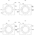
<変形例に適用可能なダイスヘッド>
さらに、図12を参照して、この変形例に係るブロー成形装置に適用可能なダイスヘッ
ドについて説明する。図12(A)〜図12(D)は、図11(C)に対応するダイスヘ
ッドの下面図の部分拡大図である。なお、図12(A)〜図12(D)に示すダイスヘッ
ドにおいても、パリソンPの内周面および外周面の少なくとも一方の面(周面)に設けら
れる加飾部である凸部が、基体層を構成する第1の成形材料とはダイスヘッドの内部にお
ける樹脂通路が異なる第2の成形材料(第1の成形材料と同じであっても構わないし第1
の成形材料とは異なる成形材料であっても構わない)により形成される点は同じである。
As described above, according to the blow molding apparatus according to this modification, the blow molding method can be realized, and the inner surface (inner peripheral surface) and the outer surface (outer peripheral surface) of the side surface can be realized with a simple manufacturing apparatus and at a low manufacturing cost.
It is possible to manufacture a blow molded article in which a linear pattern or a spiral pattern of different colors or the same color is applied to at least one surface (peripheral surface).
<Dice head applicable to modification>
Furthermore, with reference to FIG. 12, the die head applicable to the blow molding apparatus which concerns on this modification is demonstrated. 12 (A) to 12 (D) are partial enlarged views of the bottom view of the die head corresponding to FIG. 11 (C). In the dice head shown in FIGS. 12 (A) to 12 (D), the convex portion, which is a decorative portion provided on at least one surface (peripheral surface) of the inner peripheral surface and the outer peripheral surface of the parison P, The first molding material constituting the base layer may be the same as the first molding material, which is the same as the first molding material.
The molding material may be a molding material different from the above molding material).
図12(A)に示すダイスヘッド600は、基体層の外周面に1以上の加飾部(凸部)
を備えるパリソンPを押し出すためのダイスヘッドの一例である。コア670は放射状に
点在した穴である吐出通路を備えないで、ダイス680に放射状に点在した穴である吐出
通路662が形成されており、この吐出通路662の部分に対応してパリソンPの外筒面
に凸部Gが、基体層を構成する第1の成形材料とはダイスヘッド600の内部における樹
脂通路が異なる第2の成形材料により形成される。
A
It is an example of the dice head for extruding the parison P provided with. The
図12(B)に示すダイスヘッド700は、基体層の内周面および外周面に1以上の加
飾部(凸部)を備えるパリソンPを押し出すためのダイスヘッドの一例である。コア77
0は放射状に点在した穴である吐出通路762A(上述した吐出通路562に対応)を備
え、かつ、ダイス780は放射状に点在した穴である吐出通路762B(上述した吐出通
路662に対応)を備え、吐出通路762Aの部分に対応してパリソンPの内筒面に凸部
Gが、吐出通路762Bの部分に対応してパリソンPの外筒面に凸部が、基体層を構成す
る第1の成形材料とは樹脂通路が異なる第2の成形材料により形成される。なお、この場
合において、吐出通路762Aおよび吐出通路762Bに同じ第2の成形材料を供給する
ようにしても構わないし、吐出通路762Aおよび吐出通路762Bのいずれか一方に第
2の成形材料を供給し他方に第2の成形材料とは異なる第3の成形材料を供給するように
しても構わない。
A
0 includes
図12(C)に示すダイスヘッド800は、図12(B)に示したダイスヘッド700
において設けられた吐出通路である穴が、パリソンPの内周と外周とで放射状の同じ角度
位置に設けられていたのに対して、異なる角度位置に設けられていることを特徴とする。
ダイス780は放射状に点在した穴である吐出通路862B(上述した吐出通路662に
対応)を備え、コア870にはその吐出通路862Bとは放射状の異なる角度位置に点在
した穴である吐出通路862Aを備える。
The
The holes, which are the discharge passages provided in, are provided at the same angular position radially on the inner periphery and outer periphery of the parison P, but are provided at different angular positions.
The
図12(D)に示すダイスヘッド800は、図11(C)に示したダイスヘッド500
、図12(A)に示したダイスヘッド600および図12(C)に示したダイスヘッド7
00における吐出通路の点在位置が全て線対称または/および点対称であったものが、線
対称でもなく点対称でもない非対称に構成したものである。
図12に示したこのようなダイスヘッドを用いることにより、側面の内面(内周面)お
よび外面(外周面)の少なくとも一方の面(周面)に、異なる色彩または同じ色彩の直線状
の模様またはスパイラル状の複雑な模様が施されたブロー成形品を製造することができる
。
The
The
In the case where the scattered positions of the discharge passages at 00 are all line-symmetrical and / or point-symmetrical, they are configured to be asymmetrical that is neither line-symmetrical nor point-symmetrical.
By using such a dice head shown in FIG. 12, at least one surface (peripheral surface) of the inner surface (inner peripheral surface) and outer surface (outer peripheral surface) of the side surface is a linear pattern of different colors or the same color. Alternatively, it is possible to produce a blow molded product having a spiral complicated pattern.
なお、今回開示された実施の形態はすべての点で例示であって制限的なものではないと
考えられるべきである。本発明の範囲は上記した説明ではなくて特許請求の範囲によって
示され、特許請求の範囲と均等の意味および範囲内でのすべての変更が含まれることが意
図される。
The embodiment disclosed this time should be considered as illustrative in all points and not restrictive. The scope of the present invention is defined by the terms of the claims, rather than the description above, and is intended to include any modifications within the scope and meaning equivalent to the terms of the claims.
本発明は、ダイレクトブロー成形において、簡易な製造装置で安価な製造コストで、側
面の内面(内周面)および外面(外周面)の少なくとも一方の面(周面)に、異なる色彩ま
たは同じ色彩の直線状の模様またはスパイラル状の模様が施された成形品を製造する技術
に好適に利用することができる。
In the direct blow molding, at least one of the inner surface (inner peripheral surface) and the outer surface (outer peripheral surface) of the side surface (peripheral surface) is different or the same color at a low manufacturing cost with a simple manufacturing apparatus. The present invention can be suitably used for a technique for producing a molded product having a linear pattern or a spiral pattern.
10 ブロー成形装置
100 チャックユニット
200 押出ユニット
300 ブロー成形ユニット
1000 演算ユニット
10
Claims (11)
第1の成形材料を加熱溶融させた略中空円筒形状の基体層の内周面および外周面の少なくとも一方の周面から出っ張るように形成されるとともに前記パリソンの押し出し方向に沿って形成される1以上の凸部を備えた非円環断面形状のパリソンを、ダイスヘッドから下方へ押し出す押し出し機構と、
前記押し出されたパリソンを金型で挟み込んでブロー成形するブロー成形機構とを含み、
前記凸部は、前記基体層を形成する第1の成形材料とは前記ダイスヘッド内の樹脂通路が異なる第2の成形材料で形成される、ブロー成形装置。 A molding apparatus for producing a synthetic resin molded product by a blow molding method,
1 is formed so as to protrude from at least one of the inner peripheral surface and the outer peripheral surface of the substantially hollow cylindrical base layer obtained by heating and melting the first molding material, and is formed along the direction in which the parison is extruded. An extruding mechanism for extruding a parison having a non-annular cross-sectional shape having the above convex portions downward from a die head;
A blow molding mechanism for sandwiching the extruded parison with a mold and blow molding,
The said convex part is a blow molding apparatus formed with the 2nd molding material from which the resin path in the said die head differs from the 1st molding material which forms the said base | substrate layer.
前記第1の樹脂通路と前記第2の樹脂通路とは前記ダイスヘッドの内部で合流しない、請求項1に記載のブロー成形装置。 The die head includes a housing and two or more mandrels. The first resin passage through which the first melted and melted molding material flows, and the second flow through which the second melted and melted molding material flows. A resin passage,
The blow molding apparatus according to claim 1, wherein the first resin passage and the second resin passage do not merge inside the die head.
前記ブロー成形機構は、前記捻回機構により捻回されたパリソンを金型で挟み込んでブロー成形し、
前記捻回機構は、
前記押し出し機構から押し出されたパリソンの端部を把持するための把持手段と、
前記パリソンの押し出し方向に平行な軸を回転軸として、前記パリソンの端部を把持した把持手段を所定の角度分だけ回転するための回転手段とを含む、請求項1〜請求項3のいずれかに記載のブロー成形装置。 The blow molding device further includes a twisting mechanism for gripping and twisting the parison extruded from the extrusion mechanism,
The blow molding mechanism is blow molded by sandwiching a parison twisted by the twist mechanism with a mold,
The twisting mechanism is
Gripping means for gripping the end of the parison extruded from the extrusion mechanism;
The rotating means for rotating the holding means which hold | gripped the edge part of the said parison by a predetermined angle by making an axis | shaft parallel to the extrusion direction of the said parison into a rotating shaft is any one of Claims 1-3. The blow molding apparatus described in 1.
前記捻回機構は、前記パリソンの押し出し速度に対応させて前記パリソンの端部を把持した把持手段を前記回転軸方向に沿って下方へ移動するための移動手段をさらに含む、請求項4に記載のブロー成形装置。 The extrusion mechanism continuously extrudes the parison,
The said twisting mechanism further includes a moving means for moving a gripping means that grips an end of the parison in accordance with the pushing speed of the parison to move downward along the rotation axis direction. Blow molding equipment.
前記把持手段は、前記エアーの流通を阻害しないように、前記パリソンの端部を把持する、請求項4または請求項5に記載のブロー成形装置。 The extrusion mechanism extrudes the parison while circulating air through the hollow portion of the parison in order to maintain the substantially hollow cylindrical shape of the parison,
The blow molding apparatus according to claim 4 or 5, wherein the gripping means grips an end of the parison so as not to hinder the air flow.
前記所定の角度は、前記ブロー成形後の成形品における捻り角度に、前記把持が解除されたパリソンが前記金型で挟み込まれるまでに戻る角度に対応させた角度分だけ余分に加えた角度である、請求項4〜請求項6のいずれかに記載のブロー成形装置。 The blow molding mechanism blow-molds the parison released from gripping by the gripping means,
The predetermined angle is an angle obtained by adding to the twist angle in the molded product after the blow molding by an amount corresponding to an angle corresponding to a return angle until the parison whose grip is released is sandwiched between the molds. The blow molding apparatus according to any one of claims 4 to 6.
前記把持手段は、前記パリソンの端部の外筒面を一対のチャックで挟持し、
前記金型は、対向させた合わせ面が離隔接近する少なくとも2つに分割された金型であって、
前記回転手段は、前記チャックが解除されたパリソンにおいて前記チャックにより挟持されたことにより形成された略平らな平面が、前記合わせ面を含む平面と略平行になるように、前記パリソンの端部を把持した把持手段の回転を停止する、請求項4〜請求項6のいずれかに記載のブロー成形装置。 The blow molding mechanism blow-molds the parison released from gripping by the gripping means,
The gripping means sandwiches the outer cylindrical surface of the end of the parison with a pair of chucks,
The mold is a mold divided into at least two facing facing surfaces that are spaced apart from each other,
The rotating means moves the end of the parison so that a substantially flat plane formed by being held by the chuck in the parison with the chuck released is substantially parallel to a plane including the mating surface. The blow molding apparatus according to any one of claims 4 to 6, wherein rotation of the gripping means gripped is stopped.
第1の成形材料を加熱溶融させた略中空円筒形状の基体層の内周面および外周面の少なくとも一方の周面から出っ張るように形成されるとともに前記パリソンの押し出し方向に沿って形成される1以上の凸部を備えた非円環断面形状のパリソンを、ダイスヘッドから下方へ押し出す押出ステップと、
前記押し出されたパリソンを金型で挟み込んでブロー成形する成形ステップとを含み、
前記凸部は、前記基体層を形成する第1の成形材料とは前記ダイスヘッド内の樹脂通路が異なる第2の成形材料で形成される、ブロー成形方法。 A molding method for producing a molded product made of synthetic resin by a blow molding method,
1 is formed so as to protrude from at least one of the inner peripheral surface and the outer peripheral surface of the substantially hollow cylindrical base layer obtained by heating and melting the first molding material, and is formed along the direction in which the parison is extruded. Extrusion step for extruding the non-annular cross-sectional parison with the convex portions downward from the die head;
A molding step of sandwiching the extruded parison with a mold and blow molding,
The said convex part is a blow molding method formed with the 2nd molding material from which the resin channel in the said die head differs from the 1st molding material which forms the said base | substrate layer.
Priority Applications (1)
| Application Number | Priority Date | Filing Date | Title |
|---|---|---|---|
| JP2019117184A JP2019151123A (en) | 2019-06-25 | 2019-06-25 | Plastic bottle produced by blow molding method |
Applications Claiming Priority (1)
| Application Number | Priority Date | Filing Date | Title |
|---|---|---|---|
| JP2019117184A JP2019151123A (en) | 2019-06-25 | 2019-06-25 | Plastic bottle produced by blow molding method |
Related Parent Applications (1)
| Application Number | Title | Priority Date | Filing Date |
|---|---|---|---|
| JP2016022676A Division JP6595361B2 (en) | 2016-02-09 | 2016-02-09 | Blow molding apparatus and blow molding method |
Publications (1)
| Publication Number | Publication Date |
|---|---|
| JP2019151123A true JP2019151123A (en) | 2019-09-12 |
Family
ID=67947863
Family Applications (1)
| Application Number | Title | Priority Date | Filing Date |
|---|---|---|---|
| JP2019117184A Pending JP2019151123A (en) | 2019-06-25 | 2019-06-25 | Plastic bottle produced by blow molding method |
Country Status (1)
| Country | Link |
|---|---|
| JP (1) | JP2019151123A (en) |
Cited By (1)
| Publication number | Priority date | Publication date | Assignee | Title |
|---|---|---|---|---|
| CN120572720A (en) * | 2025-08-04 | 2025-09-02 | 辽宁民康制药有限公司 | Dual-mode high-speed intelligent bottle-controlling machine and manufacturing method thereof |
Citations (5)
| Publication number | Priority date | Publication date | Assignee | Title |
|---|---|---|---|---|
| JPS5027164U (en) * | 1973-07-12 | 1975-03-28 | ||
| JPS5031153U (en) * | 1973-07-12 | 1975-04-07 | ||
| JPH02102317U (en) * | 1989-01-31 | 1990-08-15 | ||
| JP2006103713A (en) * | 2004-10-01 | 2006-04-20 | Heiwa Kagaku Kogyosho:Kk | Partially multi-layered container including main layer having shape keeping property |
| JP2010005990A (en) * | 2008-06-30 | 2010-01-14 | Yoshino Kogyosho Co Ltd | Blow-molded container and molding method |
-
2019
- 2019-06-25 JP JP2019117184A patent/JP2019151123A/en active Pending
Patent Citations (5)
| Publication number | Priority date | Publication date | Assignee | Title |
|---|---|---|---|---|
| JPS5027164U (en) * | 1973-07-12 | 1975-03-28 | ||
| JPS5031153U (en) * | 1973-07-12 | 1975-04-07 | ||
| JPH02102317U (en) * | 1989-01-31 | 1990-08-15 | ||
| JP2006103713A (en) * | 2004-10-01 | 2006-04-20 | Heiwa Kagaku Kogyosho:Kk | Partially multi-layered container including main layer having shape keeping property |
| JP2010005990A (en) * | 2008-06-30 | 2010-01-14 | Yoshino Kogyosho Co Ltd | Blow-molded container and molding method |
Cited By (1)
| Publication number | Priority date | Publication date | Assignee | Title |
|---|---|---|---|---|
| CN120572720A (en) * | 2025-08-04 | 2025-09-02 | 辽宁民康制药有限公司 | Dual-mode high-speed intelligent bottle-controlling machine and manufacturing method thereof |
Similar Documents
| Publication | Publication Date | Title |
|---|---|---|
| US11697241B2 (en) | Blow molding method and apparatus for forming squeezable plastic container | |
| JP5178827B2 (en) | Method and apparatus for manufacturing hollow body made of thermoplastic material | |
| JP6595361B2 (en) | Blow molding apparatus and blow molding method | |
| US4116607A (en) | Thread forming and neck finishing apparatus | |
| US20030164572A1 (en) | Process for producing dish-shaped moldings of thermoplastic material | |
| CN107405818B (en) | Container with internal surface spiral strip, method and device for manufacturing container with internal surface spiral strip | |
| JP2019151123A (en) | Plastic bottle produced by blow molding method | |
| JP6533428B2 (en) | Blow molding apparatus and blow molding method | |
| CA2458312C (en) | Method and apparatus for blow-molding an article having a solid radially outwardly projecting flange | |
| JP2010005990A (en) | Blow-molded container and molding method | |
| JP2001322161A (en) | Method for manufacturing bottle with internal pattern by blow molding, and plastic bottle | |
| EP4640405A1 (en) | Method for manufacturing container, apparatus for manufacturing container, and container | |
| JP7327860B1 (en) | CONTAINER MANUFACTURING METHOD, CONTAINER MANUFACTURING APPARATUS, CONTAINER | |
| JPH08511999A (en) | Squeeze container | |
| JP7317453B2 (en) | Container manufacturing method and container | |
| KR101870159B1 (en) | Apparatus and method for fabricating of plastic container | |
| KR101747261B1 (en) | System and method for fabricating of plastic container | |
| KR101459526B1 (en) | A Blow Plastic Container Manufacturing Unit |
Legal Events
| Date | Code | Title | Description |
|---|---|---|---|
| A521 | Request for written amendment filed |
Free format text: JAPANESE INTERMEDIATE CODE: A523 Effective date: 20190723 |
|
| A621 | Written request for application examination |
Free format text: JAPANESE INTERMEDIATE CODE: A621 Effective date: 20190723 |
|
| A977 | Report on retrieval |
Free format text: JAPANESE INTERMEDIATE CODE: A971007 Effective date: 20200703 |
|
| A131 | Notification of reasons for refusal |
Free format text: JAPANESE INTERMEDIATE CODE: A131 Effective date: 20200707 |
|
| A521 | Request for written amendment filed |
Free format text: JAPANESE INTERMEDIATE CODE: A523 Effective date: 20200825 |
|
| A02 | Decision of refusal |
Free format text: JAPANESE INTERMEDIATE CODE: A02 Effective date: 20201027 |