JP2019152111A - Actuator for variable compression ratio mechanism for internal combustion engine and actuator used for device for internal combustion engine - Google Patents
Actuator for variable compression ratio mechanism for internal combustion engine and actuator used for device for internal combustion engine Download PDFInfo
- Publication number
- JP2019152111A JP2019152111A JP2018036291A JP2018036291A JP2019152111A JP 2019152111 A JP2019152111 A JP 2019152111A JP 2018036291 A JP2018036291 A JP 2018036291A JP 2018036291 A JP2018036291 A JP 2018036291A JP 2019152111 A JP2019152111 A JP 2019152111A
- Authority
- JP
- Japan
- Prior art keywords
- actuator
- combustion engine
- internal combustion
- compression ratio
- control shaft
- Prior art date
- Legal status (The legal status is an assumption and is not a legal conclusion. Google has not performed a legal analysis and makes no representation as to the accuracy of the status listed.)
- Pending
Links
Images




Classifications
-
- F—MECHANICAL ENGINEERING; LIGHTING; HEATING; WEAPONS; BLASTING
- F02—COMBUSTION ENGINES; HOT-GAS OR COMBUSTION-PRODUCT ENGINE PLANTS
- F02B—INTERNAL-COMBUSTION PISTON ENGINES; COMBUSTION ENGINES IN GENERAL
- F02B75/00—Other engines
- F02B75/04—Engines with variable distances between pistons at top dead-centre positions and cylinder heads
-
- F—MECHANICAL ENGINEERING; LIGHTING; HEATING; WEAPONS; BLASTING
- F02—COMBUSTION ENGINES; HOT-GAS OR COMBUSTION-PRODUCT ENGINE PLANTS
- F02B—INTERNAL-COMBUSTION PISTON ENGINES; COMBUSTION ENGINES IN GENERAL
- F02B75/00—Other engines
- F02B75/32—Engines characterised by connections between pistons and main shafts and not specific to preceding main groups
-
- F—MECHANICAL ENGINEERING; LIGHTING; HEATING; WEAPONS; BLASTING
- F02—COMBUSTION ENGINES; HOT-GAS OR COMBUSTION-PRODUCT ENGINE PLANTS
- F02D—CONTROLLING COMBUSTION ENGINES
- F02D15/00—Varying compression ratio
- F02D15/02—Varying compression ratio by alteration or displacement of piston stroke
Landscapes
- Engineering & Computer Science (AREA)
- Chemical & Material Sciences (AREA)
- Combustion & Propulsion (AREA)
- Mechanical Engineering (AREA)
- General Engineering & Computer Science (AREA)
- Output Control And Ontrol Of Special Type Engine (AREA)
- Retarders (AREA)
Abstract
【課題】 軸長を短縮化できる内燃機関の可変圧縮比機構のアクチュエータおよび内燃機関用機器に用いられるアクチュエータを提供する。【解決手段】 可撓性外歯車36のボス部363は、底部362から少なくとも一部が胴部361と同じ側へ延びて第2制御軸11と連結する。【選択図】 図4PROBLEM TO BE SOLVED: To provide an actuator of a variable compression ratio mechanism of an internal combustion engine capable of shortening an axial length and an actuator used in an equipment for an internal combustion engine. SOLUTION: A boss portion 363 of a flexible external gear 36 extends at least a part from a bottom portion 362 to the same side as a body portion 361 and is connected to a second control shaft 11. [Selection diagram] Fig. 4
Description
本発明は、内燃機関の可変圧縮比機構のアクチュエータおよび内燃機関用機器に用いられるアクチュエータに関する。 The present invention relates to an actuator for a variable compression ratio mechanism of an internal combustion engine and an actuator used for an internal combustion engine device.
特許文献1には、可変圧縮比機構の制御軸の回転位置を変更するアクチュエータとして、電動モータの回転速度を波動歯車減速機により減速して制御軸へ伝達するアクチュエータが開示されている。波動歯車減速機の可撓性外歯車は、筒状の胴部と、胴部の一端側を塞ぐダイヤフラムと、ダイヤフラムの中心に一体成形され制御軸と連結するボス部とを有する。 Patent Literature 1 discloses an actuator that reduces the rotational speed of an electric motor by a wave gear reducer and transmits it to the control shaft as an actuator that changes the rotational position of the control shaft of the variable compression ratio mechanism. The flexible external gear of the wave gear reducer includes a cylindrical body, a diaphragm that closes one end of the body, and a boss that is integrally formed at the center of the diaphragm and is connected to the control shaft.
しかしながら、上記従来技術にあっては、ボス部がダイヤフラムを挟んで胴部と反対側に配置されているため、アクチュエータの軸長が長くなり、車両搭載レイアウトが不利となるおそれがあった。
本発明の目的の一つは、軸長を短縮化できる内燃機関の可変圧縮比機構のアクチュエータおよび内燃機関用機器に用いられるアクチュエータを提供することにある。
However, in the above prior art, since the boss part is arranged on the opposite side of the body part across the diaphragm, there is a possibility that the axial length of the actuator becomes long and the vehicle mounting layout becomes disadvantageous.
One of the objects of the present invention is to provide an actuator for a variable compression ratio mechanism of an internal combustion engine and an actuator used for an internal combustion engine device that can shorten the axial length.
本発明の一実施形態における内燃機関の可変圧縮比機構のアクチュエータにおいて、ボス部は、底部から少なくとも一部が胴部と同じ側へ延びて制御軸と連結する。 In the actuator of the variable compression ratio mechanism of the internal combustion engine according to the embodiment of the present invention, the boss portion extends from the bottom portion to the same side as the body portion and is connected to the control shaft.
よって、本発明にあっては、アクチュエータの軸長を短縮化できる。 Therefore, in the present invention, the axial length of the actuator can be shortened.
〔実施形態1〕
図1は、実施形態1の可変圧縮比機構のアクチュエータを備えた内燃機関の概略図である。基本的な構成は、例えば特開2011-169251号公報の図1に記載されたものと同じであるため、簡単に説明する。
ピストン1は、内燃機関(ガソリンエンジン)におけるシリンダブロックのシリンダ内を往復運動する。ピストン1には、ピストンピン2を介してアッパリンク3の上端が回転可能に連結する。アッパリンク3の下端には、連結ピン6を介してロアリンク5が回転可能に連結する。ロアリンク5には、クランクピン4aを介してクランクシャフト4が回転可能に連結する。ロアリンク5には、連結ピン8を介して第1制御リンク7の上端部が回転可能に連結する。第1制御リンク7の下端部は、複数のリンクを有する連結機構9と連結する。連結機構9は、第1制御軸10、第2制御軸(制御軸)11、第2制御リンク12およびアームリンク13を有する。
Embodiment 1
FIG. 1 is a schematic view of an internal combustion engine provided with an actuator of a variable compression ratio mechanism according to a first embodiment. The basic configuration is the same as that described in FIG. 1 of Japanese Patent Application Laid-Open No. 2011-169251, for example, and will be described briefly.
The piston 1 reciprocates in a cylinder of a cylinder block in an internal combustion engine (gasoline engine). The upper end of the
第1制御軸10は、内燃機関内部の気筒列方向に沿って配置されたクランクシャフト4と平行に配置されている。第1制御軸10は、第1ジャーナル部10a、制御偏心軸部10b、偏心軸部10c、第1アーム部10dおよび第2アーム部10eを有する。第1ジャーナル部10aは、内燃機関本体に回転可能に支持されている。制御偏心軸部10bは、第1制御リンク7の下端部と回転可能に連結する。偏心軸部10cは、第2制御リンク12の一端部12aと回転可能に連結する。第1アーム部10dの一端は、第1ジャーナル部10aと連結する。第1アーム部10dの他端は、制御偏心軸部10bと連結する。制御偏心軸部10bは、第1ジャーナル部10aに対して所定量偏心した位置にある。第2アーム部10eの一端は、第1ジャーナル部10aと連結する。第2アーム部10eの他端は、偏心軸部10cと連結する。偏心軸部10cは、第1ジャーナル部10aに対して所定量偏心した位置にある。第2制御リンク12の他端部12bは、アームリンク13の一端が回転可能に連結する。アームリンク13の他端は、第2制御軸11と連結する。アームリンク13と第2制御軸11は相対移動しない。第2制御軸11は、後述するハウジング20内に回転可能に収容されている。第2制御リンク12は、レバー形状であり、偏心軸部10cに連結された一端部12aは、略直線的に形成されている。
The
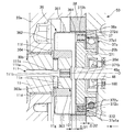
図2は実施形態1の可変圧縮比機構のアクチュエータ40の分解斜視図、図3はアクチュエータ40の側面図、図4は図3のS4-S4線矢視断面図である。
図2の分解斜視図に示すように、第2制御リンク12の他端部12bは、湾曲形成され、アームリンク13が連結されている。第2制御リンク12の一端部12aの先端部には、偏心軸部10cが回動自在に挿通される挿通孔12cが貫通形成されている。他端部12bは、先端部12dを有する。先端部12dには、連結用孔12eが貫通形成されている。アームリンク13は、第2制御リンク12とは別体に形成されている。アームリンク13は、円環状部13dおよび1対のアーム部13b1,13b2を有する。円環状部13dには、圧入用孔13aが貫通形成されている。圧入用孔13aは、第2制御軸11の各ジャーナル部11c,11d間に形成された固定部11bが圧入されている。1対のアーム部13b1,13b2は、円環状部13dから外周に向けて突出する二股状に形成されている。1対のアーム部13b1,13b2には、連結用孔13cがそれぞれ貫通形成されている。1対のアーム部13b1,13b2の間には、第2制御リンク12の先端部12dが挿通されている。各連結用孔12e,13c,13cには、連結ピン14が挿入されている。各連結用孔12e,13c,13cの中心(連結ピン14の軸心)は、第2制御軸11の軸心に対して所定量偏心している。
2 is an exploded perspective view of the
As shown in the exploded perspective view of FIG. 2, the
アクチュエータ40は、駆動モータ22、波動歯車減速機50、ハウジング20および第2制御軸11を有する。以下、駆動モータ22のモータ軸48の回転軸線Oに沿う方向を軸方向、回転軸線Oの放射方向を径方向、回転軸線O周りの方向を周方向という。また、軸方向にX軸を設定し、X軸方向において、モータ軸48の側から第2制御軸11の側へ向かう方向を正方向、第2制御軸11の側からモータ軸48の側へ向かう方向をX軸負方向と定義する。
アクチュエータ40は、駆動モータ22の回転速度を波動歯車減速機50により減速して第2制御軸11へ伝達することにより、第2制御軸11の回転位置を変更する。第2制御軸11の回転位置が変更されると、第2制御リンク12の姿勢が変化して第1制御軸10が回転し、第1制御リンク7の下端部の位置が変更される。これにより、ロアリンク5の姿勢が変化し、ピストン1のシリンダ内におけるストローク位置やストローク量が変わる。この結果、内燃機関の機関圧縮比を変更できる。
The
The
駆動モータ22は、例えばDCブラシレスモータであり、モータケーシング45、コイル46、ロータ47およびモータ軸48を有する。モータケーシング45は、有底円筒状に形成され、ハウジング20の第2ハウジング20bに固定されている。コイル46は、モータケーシング45の内周面に固定されている。ロータ47は、コイル46の内側に回転可能に配置されている。モータ軸48は、ロータ47の中心に固定されている。モータ軸48は、2つのボールベアリング51,52を介して第2ハウジング20bおよびモータケーシング45に対し回転可能に設けられている。ボールベアリング51は第2ハウジング20bに固定されている。ボールベアリング52はモータケーシング45の底部に固定されている。モータ軸48のX軸正方向側の先端部48aは、第2ハウジング20bを貫通し、波動歯車減速機50の波動発生器37の波動発生プラグ371と連結する。
The
第2制御軸11は、モータ軸48のX軸正方向側に位置し、モータ軸48と同軸である。つまり、第2制御軸11およびモータ軸48は、同一の回転軸線Oを持つ。第2制御軸11のX軸負方向側の端部(制御軸第1端部)11aは、波動歯車減速機50の可撓性外歯車36のボス部363と連結する。
モータケーシング45は、複数のボス部45aを有する。各ボス部45aには、ボルト49を通すボルト穴45bが形成されている。ボルト49が第2ハウジング20bに形成された雌ねじ部20b1にねじ込まれることにより、モータケーシング45が第2ハウジング20bに固定されている。モータケーシング45および第2ハウジング20bの内部は、シール100によって潤滑油等を供給しない乾燥室に維持されている。
The
The
波動歯車減速機50は、ハウジング20に収容されている。波動歯車減速機50は、剛性内歯車(内歯車)38、可撓性外歯車36および波動発生器37を有する。
剛性内歯車38は、内周に複数の内歯38aを有する剛体円環状部材である。剛性内歯車38は、ハウジング20の第1ハウジング20aに固定されている。
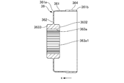
可撓性外歯車36は、剛性内歯車38の径方向内側に配置されている。図5は、実施形態1の可撓性外歯車36を示す図であり、(a)は正面図、(b)は右側面図、(c)は(a)のc-c線矢視断面図である。可撓性外歯車36は、金属材料によって形成され、胴部361、底部362およびボス部(第1ボス部)363を有する。
胴部361は、撓み変形可能な薄肉の円筒状に形成されている。X軸負方向端部(胴部第2端部)361bは開口する。胴部361の外周面のX軸負方向側には、外歯364が形成されている。外歯364は、剛性内歯車38の内歯38aと噛み合う。外歯364の歯数は内歯38aの歯数よりも2歯少ない。
底部362は、胴部361のX軸正方向端部(胴部第1端部)361aから径方向内側へ延びる。底部362の肉厚は胴部361の肉厚と略一致する。
The
The rigid
The flexible
The
The
ボス部363は、底部362からX軸負方向側へ延びる円筒状に形成されている。ボス部363のX軸負方向端は、胴部361のX軸負方向端よりもX軸正方向側に位置する。つまり、ボス部363は、全て胴部361の内側に位置する。また、ボス部363は、X軸負方向側の一部が外歯364とX軸方向にオーバーラップしている。ボス部363は、その内周に孔部363aを有する。孔部363aは、その内周面に、周方向に並ぶ複数の波状溝(溝部)363a1を有する。つまり、孔部363aはスプライン穴であり、波状溝363a1は、スプライン穴の各溝である。孔部363aには、第2制御軸11の端部11aが挿入されている。端部11aは、その外周面に、周方向に並び波状溝363a1と嵌合可能な複数の波状突起(突起部)11a1を有する。つまり、端部11aは、スプライン軸であり、波状突起11a1は、スプライン軸の各突起である。波状溝363a1および波状突起11a1は、周方向において第2制御軸11とボス部363とを噛み合わせると共に、X軸方向において第2制御軸11とボス部363との相対移動を許容する結合部101である。波状溝363a1および波状突起11a1の回転軸線Oと直交する断面の形状は、インボリュート曲線を用いて形成されている。すなわち、結合部101は、インボリュートスプラインである。波状溝363a1および波状突起11a1は、径方向に所定のガタを有して噛み合わされている。このため、端部11aは、孔部363aに対して、径方向に所定の範囲だけ相対移動可能である。
The
波動発生器37は、その外周面が可撓性外歯車36の内周面に沿って摺動する。波動発生器37は、波動発生プラグ371およびボールベアリング(転がり軸受)372を有する。波動発生プラグ371は、回転軸線Oと直交する断面の外形が楕円状であって、回転軸線Oを中心として最も半径の大きい長軸部分および最も半径の小さい短軸部分を有する楕円状外形を有する。波動発生プラグ371は、ボールベアリング37aを介して第2ハウジング20bに対し回転可能に支持されている。波動発生プラグ371は中心に貫通孔371bを有する。貫通孔371bには、モータ軸48の先端部48aが圧入されている。波動発生プラグ371のX軸正方向側の端面は突き当て面371aである。突き当て面371aは、ボス部363と当接し、ボス部363のX軸負方向側への移動を規制する。このため、図6に示すように、X軸方向において、ボス部363および突き当て面371a間のクリアランスΔD1は、胴部361のX軸負方向端部361bおよびボールベアリング37a間のクリアランスΔD2よりも小さく設定されている。ボールベアリング372は、波動発生プラグ371の外周および可撓性外歯車36の内周間の相対回転を許容する。図4に示すように、ボールベアリング372は、内輪372a、外輪372b、複数のボール372cおよび保持器372dを有する。内輪372aは、波動発生プラグ371の外周面と一体的に形成されている。外輪372bは、可撓性を有する薄肉の環状に形成され、可撓性外歯車36の内周と接する。複数のボール372cは、球状に形成され、内輪372aおよび外輪372b間に配置されている。保持器372dは、内輪372aおよび外輪372b間に配置され、各ボール372cの間隔を一定に保持する。
The outer peripheral surface of the
ハウジング20は、第1ハウジング20aおよび第2ハウジング20bを有し、アルミニウム合金材料によって略立方体形状に形成されている。第1ハウジング20aのX軸負方向側には大径円環状の開口溝部20cが形成されている(図4参照)。この開口溝部20cは、第2ハウジング20bにより閉塞される。第2ハウジング20bは、中央位置にモータ軸48が貫通するモータ軸貫通孔20dと、径方向外周側に向けて拡径された4つのボス部20eとを有する。第1ハウジング20aと第2ハウジング20bとは、ボス部20eに挿通されたボルト35により締結されている。
The
第1ハウジング20aにおいて、開口溝部20cよりもX軸正方向側の側面には、アームリンク13と連結された第2制御リンク12用の開口(不図示)が形成されている。この開口が形成された第1ハウジング20aの内部には、アームリンク13および第2制御リンク12の作動領域となる収容室29が形成されている(図4参照)。X軸方向において、開口溝部20cと収容室29との間には、第2制御軸11の第2ジャーナル部11dが貫通する支持孔30bが形成されている。また、収容室29のX軸正方向側には、第2制御軸11の第1ジャーナル部11cが貫通する支持孔30aが形成されている。支持孔30aの内周面と第1ジャーナル部11cの外周面との間には、軸受部としての軸受301が配置されている。支持孔30bの内周面と第2ジャーナル部11dの外周面との間には、軸受部としての軸受304が配置されている。軸受301および第1ジャーナル部11c間の径方向のガタ、および軸受304および第2ジャーナル部11d間の径方向のガタは、波状溝363a1および波状突起11a1間の径方向のガタよりも小さい。
支持孔30aのX軸正方向側には、リテーナ収容孔31が形成されている。リテーナ収容孔31の内径は、支持孔30aの内径よりも大きい。リテーナ収容孔31と支持孔30aとは段差面31aにより接続されている。段差面31aは、回転軸線Oと直交する。リテーナ収容孔31には、リテーナ350が収容されている。リテーナ350は、円環状に形成され、第2制御軸11が圧入されている。リテーナ350は、段差面31aとX軸方向に当接することにより、第2制御軸11のX軸負方向側への移動を規制する。
In the
A
ハウジング20のX軸正方向端には、角度センサ32が取り付けられている。角度センサ32は、第2制御軸11の回転角度を検出する。角度センサ32により検出された回転角度は、モータケーシング45に収容された駆動モータ22のコントロールユニット(不図示)へと送られる。角度センサ32は、リテーナ収容孔31をハウジング20の外部から閉塞するように取り付けられたセンサホルダ32aを有する。センサホルダ32aは、ボルト321により第1ハウジング20aに固定するためのフランジ部32a1を有する。センサホルダ32aおよび第1ハウジング20a間には、シールリング33が設置されている。シールリング33は、リテーナ収容孔31と外部との間の液密性を確保する。また、センサホルダ32aの外側には、リテーナ収容孔31を閉塞するセンサカバー32cを有する。センサカバー32cとセンサホルダ32aとの間には、シールリング323が設置されている。シールリング323は、リテーナ収容孔31と外部との間の液密性を確保する。センサカバー32cは、ボルト34によりセンサホルダ32aに締結されている。
角度センサ32のロータ32bは、楕円環状に形成され、第2制御軸11のX軸正方向側の端部(制御軸第2端部)11eに固定されている。角度センサ32は、いわゆるレゾルバであって、ロータ32bの回転に伴うセンサホルダ32aの内周とロータ32bの外周との距離の変化を検知コイル(不図示)のインダクタンス変化により検出する。これにより、ロータ32bの回転位置、すなわち第2制御軸11の回転角度を検出する。
An
The
第2制御軸11の外周面において、端部11aのX軸正方向側には、フランジ(規制部)11fが形成されている。フランジ11fは、可撓性外歯車36のボス部363と当接し、可撓性外歯車36のX軸正方向への移動を規制する。フランジ11fの外径は、ボス部363の外径よりも小さい。端部11aは、フランジ11fとの連結部分において、径方向内側に凹む環状の逃げ溝(溝)11gを有する。
第2制御軸11は、供給油路111を有する。供給油路111は、軸心油路111aおよび径方向油路111bを有する。軸心油路111aは、第2制御軸11の中心をX軸方向に延び、第2制御軸11のX軸負方向端に開口する。軸心油路111aには、第1ハウジング20aに形成された油路(不図示)を介して、図外のオイルポンプから圧送された潤滑油が導入される。軸心油路111aのX軸負方向端には、オリフィス111cが取り付けられている。軸心油路111a(オリフィス111c)のX軸負方向端から第2制御軸11の外部に流出した潤滑油は、波動発生器37および結合部101の潤滑に供される。径方向油路111bは、軸心油路111aから径方向外側へ延び、逃げ溝11gに開口する。軸心油路111aから第2制御軸11の外部に流出した潤滑油は、波動発生器37および結合部101の潤滑に供される。
On the outer peripheral surface of the
The
次に、実施形態1の作用効果を説明する。
実施形態1のアクチュエータ40において、ボス部363は、底部362から少なくとも一部がX軸負方向側へ延びて第2制御軸11と連結する。つまり、ボス部363の少なくとも一部は、胴部361の径方向内側に位置する。このため、胴部361の回転軸線に沿う方向において、ボス部が底部を挟んで胴部361と反対側へ配置された従来のアクチュエータと比べて、可撓性外歯車36の軸長を短くできる。この結果、アクチュエータ40の軸長を短縮化でき、車両搭載レイアウトの自由度を向上できる。
また、上記従来のアクチュエータと比べて、X軸方向における内歯38aと外歯364との噛み合い位置からボス部363までの距離を短くできる。このため、可撓性外歯車36の楕円変形時において、内歯38aと外歯364との噛み合い位置を支点とした場合、力点(ボス部363)までのX軸方向の距離を短くできる。これにより、図6に示すように、可撓性外歯車36における強度最弱部位である、底部362とボス部363との連結部分(隅R部分)Aに作用する楕円変形応力を抑えられる。この結果、許容トルクが増大し、より高トルクに対応した強度が得られるため、内燃機関の可変圧縮比機構のアクチュエータとして有利となる。
Next, the effect of Embodiment 1 is demonstrated.
In the
Further, compared to the conventional actuator, the distance from the meshing position of the
実施形態1のアクチュエータ40は、第2制御軸11およびボス部363に設けられ、第2制御軸11とボス部363とが噛み合う結合部101を有する。内燃機関の作動時、内燃機関の膨張行程における爆発力は可変圧縮比機構を介して第2制御軸11に径方向の荷重を与える。このとき、従来のアクチュエータでは、第2制御軸がボス部に固定されているため、可変圧縮比機構側から径方向の荷重を受けて第2制御軸が撓むと、可撓性外歯車の胴部361は回転軸線に対して傾く。可撓性外歯車が傾くと、外歯と内歯との噛み合いが悪化すると共に、波動発生器のベアリングに作用する負荷が大きくなるため、伝達効率の低下を招く。これに対し、実施形態1では、第2制御軸11が撓んで端部11aが径方向に移動した場合であっても、結合部101により端部11aの径方向変位を吸収できるため、可撓性外歯車36の傾きが抑えられる。これにより、外歯364と内歯38aとの噛み合いが良好に維持されると共に、ボールベアリング372に作用する負荷を小さくできるため、伝達効率の低下を抑制できる。この結果、駆動モータ22の出力トルクの伝達ロスが小さくなるため、駆動モータ22の消費電力を抑制できる。
The
結合部101は、第2制御軸11の外周面に設けられた波状突起11a1と、ボス部363の内周面に設けられた波状溝363a1とを有し、波状突起11a1と波状溝363a1とは、径方向にガタを有する。これにより、結合部101は、径方向のガタによって第2制御軸11の撓みに起因する端部11aの径方向変位を吸収できる。
結合部101は、第2制御軸11およびボス部363間のX軸方向の相対移動を許容する。内燃機関の作動時、第2制御軸11は、内燃機関の膨張行程における爆発力に起因して可変圧縮比機構から逆入力を受ける。このとき、現在の圧縮比を維持するために、駆動モータ22の出力トルクで逆入力トルクを打ち消す場合、胴部361が捩れてX軸方向の荷重が発生する。ここで、上記従来のアクチュエータでは、X軸方向の荷重により胴部361がX軸方向に変位したとき、第2制御軸に固定されたボス部363はX軸方向に移動しないため、底部362とボス部363との連結部分の隅に応力集中が生じるおそれがあった。これに対し、実施形態1では、ボス部363が第2制御軸11に対しX軸方向に移動可能であるため、ボス部363は胴部361に追従してX軸方向に変位可能である。これにより、底部362とボス部363との連結部分Aに生じる応力集中を緩和できる。
The
The
結合部101において、波状突起11a1は、スプライン軸(端部11a)の各突起であり、波状溝363a1は、スプライン穴(孔部363a)の各溝である。つまり、第2制御軸11とボス部363との連結は、スプライン嵌合である。スプライン嵌合は、周方向に多数の噛み合い部を持つため、可変圧縮比機構のように、内燃機関側からトルク入力を受けた状態で第2制御軸11を正逆回転させたり、一定の角度を維持したりするような使われ方をするものにおいて、第2制御軸11の傾きや径方向変位によらず、第2制御軸11およびボス部363間のトルク伝達状態を保持できる。また、従来のアクチュエータでは、底部を挟んで胴部361と反対側にボス部363があるため、可撓性外歯車の楕円変形時に胴部361とボス部363との連結部分に応力が集中して破損しやすい。内側にボス部363を設置することでスプライン嵌合での強度を満足させつつ、可撓性外歯車36で衝撃荷重を吸収し、各噛み合い部に発生する異音を低減できる。
端部11aおよび孔部363aは、インボリュートスプラインである。これにより、第2制御軸11を正逆回転させたり、一定の角度を維持したりする際、可撓性外歯車36にトルク負荷が作用したとき、第2制御軸11の回転軸線と可撓性外歯車36の回転軸線とを一致させる方向の力が作用して自動調心される。この結果、スプライン嵌合の各噛み合い部における摩耗を抑制できる。また、組み付け時にも第2制御軸11と可撓性外歯車36とが自動調心されるため、第2制御軸11と可撓性外歯車36との軸ずれを抑制でき、性能の安定性に優れている。
In the
The
第2制御軸11の端部11aは、胴部361の径方向内側でボス部363の孔部363aに挿入されている。つまり、第2制御軸11とボス部363との結合部101が胴部361とX軸方向にオーバーラップしているため、アクチュエータ40の軸長を短縮化できる。
ボス部363は、X軸負方向側へ移動したとき波動発生器37と当接可能である。これにより、ボス部363が可撓性外歯車36の抜け止めとして機能し、可撓性外歯車36の端部11aからの脱落を防止できる。
波動発生器37は、ボス部363のX軸負方向側への移動を規制する突き当て面371aを有する。これにより、可撓性外歯車36のX軸負方向側への移動を許容しつつ、その移動範囲を規制でき、可撓性外歯車36の端部11aからの脱落を防止できる。
The
The
The
第2制御軸11は、底部362のX軸正方向側への移動を規制するフランジ11fを有する。これにより、可撓性外歯車36のX軸正方向側への移動を許容しつつ、その移動範囲を規制できる。この結果、可撓性外歯車36のハウジング20または軸受304との摺接に起因する、機関圧縮比の制御機能低下および摺接部位の損傷を防止できる。なお、第2制御軸11と可撓性外歯車36は一体的に回転するため、機関圧縮比の制御機能低下や摺接部位の損傷は生じない。
フランジ11fの外径は、ボス部363の外径よりも小さい。これにより、フランジ11fとの突き当て状態のとき、フランジ11fから受けるスラスト荷重が底部362の薄肉部分に入力されるのを防げるため、可撓性外歯車36の破損を抑制できる。
ボス部363は、全て胴部361の径方向内側にある。つまり、ボス部363が全長に亘り胴部361とX軸方向にオーバーラップしているため、アクチュエータ40の軸長を短縮化できる。
The
The outer diameter of the
The
第2制御軸11は、胴部361の径方向内側へ開口し、胴部361の径方向内側に潤滑油を供給する供給油路111を有する。これにより、可撓性外歯車36の径方向内側から、外歯364と内歯38aとの噛み合い位置および波動発生器37のボールベアリング372に潤滑油を供給できる。実施形態1では、ボス部363が胴部361の径方向内側に位置するため、X軸方向において、第2制御軸11の端部11aと上記被潤滑部位との距離を詰められる。よって、供給油路111と被潤滑部位との距離が近いため、より近くから潤滑油を供給でき、潤滑性を向上できる。加えて、可撓性外歯車36はカップ状であるため、内側に潤滑油が溜まりやすく、潤滑効果を向上できる。また、供給油路111は、波状溝363a1および波状突起11a1間の径方向のガタを介して結合部101に潤滑油を供給できるため、スプライン嵌合の各噛み合い部における摩耗を抑制できる。
The
第2制御軸11の端部11aは、フランジ11fとの連結部分において、径方向内側に凹む環状の逃げ溝11gを有する。ここで、仮にボス部363側に面取りやR部等の逃げ形状を設けた場合、薄肉部分(底部362)とのつながりに近い部分の肉厚が薄くなり、強度が低下するおそれがある。これに対し、第2制御軸11側に逃げ溝11gを設けたことにより、ボス部363の根元部分(X軸正方向端部)における肉厚を確保でき、ボス部363の強度低下を抑制できる。また、ボス部363のフランジ11fに対する当接面積が大きくなるため、スラスト荷重に対する耐久性を向上できる。
ボス部363は、少なくとも一部が外歯364とX軸方向にオーバーラップする。これにより、アクチュエータ40の軸長を短縮化できる。また、X軸方向における内歯38aと外歯364との噛み合い位置からボス部363までの距離を短くできるため、底部362とボス部363との連結部分Aに作用する楕円変形応力を抑制できる。
波状溝363a1および波状突起11a1間の径方向のガタは、軸受301および第1ジャーナル部11c間の径方向のガタ、および軸受304および第2ジャーナル部11d間の径方向のガタよりも大きい。これにより、第2制御軸11が撓んだ場合であっても、波状突起11a1の先端が波状溝363a1の底部に当たらないため、伝達効率の低下を抑制できる。
The
The
The radial play between the wavy groove 363a1 and the wavy projection 11a1 is larger than the radial play between the bearing 301 and the
〔実施形態2〕
実施形態2の基本的な構成は実施形態1と同じであるため、実施形態1と相違する部分のみ説明する。
図7は、実施形態2のアクチュエータ40を示す図4の要部拡大図である。
実施形態2では、X軸方向において、ボス部363および突き当て面371a間のクリアランスΔD1は、胴部361のX軸負方向端部361bおよびボールベアリング37a間のクリアランスΔD2よりも大きく設定されている。このため、実施形態2では、可変圧縮比機構36がX軸負方向側へ移動した場合、胴部361のX軸負方向端部361bは、ボールベアリング37aの外輪37a1のX軸正方向側の端面である突き当て面37a1aに当接し、X軸負方向側への移動が規制される。
実施形態2のハウジング20は、胴部361のX軸負方向側への移動を規制する突き当て面37a1aを有する。これにより、可撓性外歯車36のX軸負方向側への移動を許容しつつ、その移動範囲を規制でき、可撓性外歯車36の端部11aからの脱落を防止できる。
[Embodiment 2]
Since the basic configuration of the second embodiment is the same as that of the first embodiment, only portions different from the first embodiment will be described.
FIG. 7 is an enlarged view of a main part of FIG. 4 showing the
In the second embodiment, in the X-axis direction, the clearance ΔD1 between the
The
〔実施形態3〕
実施形態3の基本的な構成は実施形態1と同じであるため、実施形態1と相違する部分のみ説明する。
図8は、実施形態3の可撓性外歯車36を示す図5(a)のc-c線矢視断面図である。
可撓性外歯車36は、底部362からX軸負方向側へ延びる第1ボス部3632、底部362からX軸正方向側へ延びる第2ボス部3633を有する。第1ボス部3632および第2ボス部3633の外径および底部362からのX軸方向長さは同じである。第1ボス部3632および第2ボス部3633は、その内周に孔部363aを有する。孔部363aは、その内周面に、波状溝(溝部)363a1を有する。
実施形態3では、底部362からX軸負方向側へ延びる第1ボス部3632と、底部362からX軸正方向側へ延び、第1ボス部3632と共に第2制御軸11と連結する第2ボス部3633と、を有する。これにより、第2ボス部3633を設けない場合と比べて、可撓性外歯車36における第2制御軸11との連結部分をX軸方向に長く取れるため、可撓性外歯車36の耐トルク性を向上できる。
[Embodiment 3]
Since the basic configuration of the third embodiment is the same as that of the first embodiment, only the differences from the first embodiment will be described.
FIG. 8 is a cross-sectional view taken along the line cc of FIG. 5 (a) showing the flexible
The flexible
In the third embodiment, a
〔実施形態4〕
実施形態4の基本的な構成は実施形態1と同じであるため、実施形態1と相違する部分のみ説明する。
図9は、実施形態4の可撓性外歯車36を示す図であり、(a)は正面図、(b)は右側面図、(c)は(a)のc-c線矢視断面図である。なお、図9(a)には、第2制御軸11の端部11aの正面図を記載している。
端部11aは、その外周面に、4個のキー(突起部)11a2を有する。各キー11a2は、周方向に等間隔で並ぶ。キー11a2は、矩形状に形成され、X軸方向に延びる。孔部363aは、その内周面に、4個のキー溝(溝部)363a2を有する。各キー溝363a2は、周方向に等間隔で並ぶ。各キー溝363a2は、対応するキー11a2が嵌合する。キー11a2およびキー溝363a2は、周方向において第2制御軸11とボス部363とを噛み合わせると共に、X軸方向において第2制御軸11とボス部363との相対移動を許容する結合部101である。
実施形態4では、結合部101がキー11a2およびキー11a2と嵌合するキー溝363a2を有するため、スプライン嵌合と比べて、第2制御軸11とボス部363とが互いに径方向に相対移動可能、かつ回転力を伝達可能な構造を容易に形成できる。
キー11a2およびキー溝363a2は、周方向に複数あるため、第2制御軸11を特定の回転角度で保持した際、各キー11a2およびキー溝363a2に作用する荷重を分散できる。この結果、各キー11a2およびキー溝363a2の耐久性を向上できる。
[Embodiment 4]
Since the basic configuration of the fourth embodiment is the same as that of the first embodiment, only the differences from the first embodiment will be described.
9A and 9B are diagrams showing the flexible
The
In the fourth embodiment, since the
Since there are a plurality of keys 11a2 and key grooves 363a2 in the circumferential direction, the load acting on each key 11a2 and key grooves 363a2 can be dispersed when the
〔他の実施形態〕
以上、本発明を実施するための実施形態を説明したが、本発明の具体的な構成は実施形態の構成に限定されるものではなく、発明の要旨を逸脱しない範囲の設計変更等があっても本発明に含まれる。
例えば、本発明のアクチュエータは、内燃機関の可変圧縮比機構のアクチュエータとして特に好適であるが、内燃機関においてクランク軸からのトルク伝達によりカム軸が開閉する動弁のバルブタイミングを調整するバルブタイミング調整装置にも適用可能である。
可撓性外歯車に潤滑油を供給する供給油路を、ハウジングに設けてもよい。
また、波動発生プラグの外径は必ずしも楕円状に限られず、例えば角が円弧状に形成された三角形状などの多角形状であってもよい。
[Other Embodiments]
Although the embodiment for carrying out the present invention has been described above, the specific configuration of the present invention is not limited to the configuration of the embodiment, and there are design changes and the like within the scope not departing from the gist of the invention. Are also included in the present invention.
For example, the actuator of the present invention is particularly suitable as an actuator for a variable compression ratio mechanism of an internal combustion engine. However, in the internal combustion engine, a valve timing adjustment for adjusting a valve timing of a valve that opens and closes a camshaft by torque transmission from a crankshaft. It is also applicable to the device.
A supply oil passage for supplying lubricating oil to the flexible external gear may be provided in the housing.
Further, the outer diameter of the wave generating plug is not necessarily limited to an elliptical shape, and may be a polygonal shape such as a triangular shape with corners formed in an arc shape.
以上説明した実施形態から把握し得る技術的思想について、以下に記載する。
内燃機関の可変圧縮比機構のアクチュエータは、その一つの態様において、モータ軸を回転させる駆動モータと、前記モータ軸と一体に回転し、前記モータ軸の回転軸線と直交する断面の外形が非円形である波動発生器と、所定角度範囲で回転することで前記内燃機関の可変圧縮比機構の姿勢を変化させる制御軸に連結される有底円筒状の可撓性外歯車であって、胴部と、底部と、外歯と、第1ボス部と、を有し、前記胴部は、前記波動発生器の回転により非円形に撓み変形可能な可撓性を有する筒状に形成され、前記底部は、前記回転軸線に沿う方向を軸方向としたとき、前記軸方向において、前記胴部の両端部である胴部第1端部および胴部第2端部のうち前記胴部第1端部に設けられ、前記外歯は、前記回転軸線の放射方向を径方向としたとき、前記径方向において、前記胴部の外側の面に設けられ、前記第1ボス部は、前記軸方向において、前記底部から少なくとも一部が前記胴部第2端部の側へ延びて前記制御軸と連結する、前記可撓性外歯車と、撓み変形された前記胴部の前記外歯と噛み合う内歯車と、を有する。
The technical idea that can be grasped from the embodiment described above will be described below.
An actuator of a variable compression ratio mechanism of an internal combustion engine is, in one aspect thereof, a drive motor that rotates a motor shaft and a non-circular outer shape that rotates integrally with the motor shaft and is orthogonal to the rotation axis of the motor shaft. And a bottomed cylindrical flexible external gear coupled to a control shaft that changes the attitude of the variable compression ratio mechanism of the internal combustion engine by rotating within a predetermined angle range, And the bottom portion, external teeth, and a first boss portion, and the body portion is formed in a cylindrical shape having flexibility that can be bent and deformed in a non-circular shape by rotation of the wave generator, The bottom portion has the body first end among the body first end and the body second end which are both ends of the body in the axial direction when the direction along the rotation axis is the axial direction. And the external teeth are configured such that a radial direction of the rotation axis is a radial direction. The first boss portion extends from the bottom portion toward the second end portion of the trunk portion in the axial direction. The flexible external gear connected to the control shaft, and the internal gear meshing with the external teeth of the body part that is bent and deformed.
より好ましい態様では、上記態様において、前記第1ボス部は、その内周に、前記軸方向において、前記制御軸の両端部である制御軸第1端部および制御軸第2端部のうち前記制御軸第1端部が挿入された孔部を有し、前記制御軸第1端部は、前記径方向において、前記胴部の内側に挿入されている。
別の好ましい態様では、上記態様のいずれかにおいて、前記第1ボス部と前記制御軸との連結は、スプライン嵌合である。
さらに別の好ましい態様では、上記態様のいずれかにおいて、前記第1ボス部は、前記軸方向において、前記波動発生器と当接可能である。
さらに別の好ましい態様では、上記態様のいずれかにおいて、前記制御軸は、前記軸方向において、前記第1ボス部と当接可能であり、前記可撓性外歯車の前記胴部第2端部から前記胴部第1端部へ向かう側への移動を規制する規制部を有する。
さらに別の好ましい態様では、上記態様のいずれかにおいて、前記規制部は、前記底部と当接可能なフランジであって、前記径方向において、前記フランジの外径は、前記第1ボス部の外径以下である。
In a more preferred aspect, in the above aspect, the first boss portion has, on the inner periphery thereof, the control shaft first end portion and the control shaft second end portion that are both end portions of the control shaft in the axial direction. A control shaft first end portion is inserted, and the control shaft first end portion is inserted inside the trunk portion in the radial direction.
In another preferable aspect, in any one of the above aspects, the connection between the first boss portion and the control shaft is a spline fitting.
In still another preferred aspect, in any one of the above aspects, the first boss portion can be in contact with the wave generator in the axial direction.
In still another preferred aspect, in any one of the above aspects, the control shaft can contact the first boss portion in the axial direction, and the trunk second end portion of the flexible external gear. A restricting portion for restricting movement toward the side toward the body first end.
In still another preferred aspect, in any one of the above aspects, the restricting portion is a flange capable of contacting the bottom portion, and in the radial direction, the outer diameter of the flange is outside the first boss portion. Below the diameter.
さらに別の好ましい態様では、上記態様のいずれかにおいて、前記第1ボス部は、前記径方向において、全て前記胴部の内側にある。
さらに別の好ましい態様では、上記態様のいずれかにおいて、前記可撓性外歯車は、前記軸方向において、前記底部から前記胴部第1端部の側へ延び、前記第1ボス部と共に前記制御軸と連結する第2ボス部を有する。
さらに別の好ましい態様では、上記態様のいずれかにおいて、前記波動発生器は、前記径方向において、前記可撓性外歯車の内周と接する転がり軸受を有し、前記制御軸は、前記径方向において、前記胴部の内側へ潤滑油を供給する供給油路を有する。
さらに別の好ましい態様では、上記態様のいずれかにおいて、前記制御軸は、前記軸方向において、前記可撓性外歯車の移動を規制する規制部と、前記規制部から前記胴部第2端部の側へ延びて前記第1ボス部に挿入される制御軸第1端部と、を有し、前記制御軸第1端部は、前記規制部との連結部分において、前記径方向の内側に凹む溝を有する。
さらに別の好ましい態様では、上記態様のいずれかにおいて、前記第1ボス部は、前記軸方向において、少なくとも一部が前記外歯とオーバーラップする。
In still another preferred aspect, in any one of the above aspects, the first boss portion is entirely inside the trunk portion in the radial direction.
In still another preferred aspect, in any one of the above aspects, the flexible external gear extends in the axial direction from the bottom portion toward the body first end portion, and is controlled together with the first boss portion. A second boss portion connected to the shaft is included.
In still another preferred aspect, in any one of the above aspects, the wave generator includes a rolling bearing in contact with an inner periphery of the flexible external gear in the radial direction, and the control shaft is in the radial direction. And a supply oil passage for supplying lubricating oil to the inside of the body portion.
In still another preferred aspect, in any one of the above aspects, the control shaft includes a restriction portion that restricts movement of the flexible external gear in the axial direction, and the body portion second end portion from the restriction portion. A control shaft first end that extends into the first boss portion and is inserted into the first boss portion, and the control shaft first end is on the inner side in the radial direction at a connecting portion with the restricting portion. Has a recessed groove.
In still another preferred aspect, in any one of the above aspects, at least a part of the first boss portion overlaps the external teeth in the axial direction.
また、他の観点から、内燃機関用機器に用いられるアクチュエータは、ある態様において、モータ軸を回転させる駆動モータと、前記モータ軸と一体に回転し、前記出力軸の回転軸線と直交する断面の外形が非円形である波動発生器と、所定角度範囲で回転することで前記内燃機関用機器の姿勢を変化させる制御軸に連結される有底円筒状の可撓性外歯車であって、胴部と、底部と、外歯と、第1ボス部と、を有し、前記胴部は、前記波動発生器の回転により非円形に撓み変形可能な可撓性を有する筒状に形成され、前記底部は、前記回転軸線に沿う方向を軸方向としたとき、前記軸方向において、前記胴部の両端部である胴部第1端部および胴部第2端部のうち前記胴部第1端部に設けられ、前記外歯は、前記回転軸線の放射方向を径方向としたとき、前記径方向において、前記胴部の外側の面に設けられ、前記第1ボス部は、前記軸方向において、前記底部から少なくとも一部が前記胴部第2端部の側へ延びて前記制御軸と連結する、前記可撓性外歯車と、撓み変形された前記胴部の前記外歯と噛み合う内歯車と、を有する。 From another point of view, an actuator used for an internal combustion engine device, in one aspect, has a drive motor that rotates a motor shaft and a cross section that rotates integrally with the motor shaft and is orthogonal to the rotation axis of the output shaft. A non-circular wave generator and a bottomed cylindrical flexible external gear coupled to a control shaft that changes the attitude of the internal combustion engine device by rotating within a predetermined angular range, A body portion, a bottom portion, an external tooth, and a first boss portion, and the body portion is formed in a cylindrical shape having flexibility that can be bent and deformed in a non-circular shape by rotation of the wave generator, The bottom portion has a body first portion out of a body first end portion and a body second end portion which are both ends of the body portion in the axial direction when the direction along the rotation axis is an axial direction. The outer teeth are provided at the end, and the radial direction is the radial direction of the rotation axis. In the radial direction, the first boss portion is provided on the outer surface of the trunk portion, and at least a part of the first boss portion extends from the bottom portion toward the second end portion of the trunk portion in the axial direction. The flexible external gear connected to the control shaft, and the internal gear meshing with the external teeth of the body part that is bent and deformed.
O 回転軸線
11 第2制御軸(制御軸)
11a 端部(制御軸第1端部)
11e 端部(制御軸第2端部)
11g 逃げ溝(溝)
20 ハウジング
22 駆動モータ
36 可撓性外歯車
361 胴部
361a X軸正方向端部(胴部第1端部)
361b X軸負方向端部(胴部第2端部)
362 底部
363 ボス部(第1ボス部)
363a 孔部
3632 第1ボス部
3633 第2ボス部
364 外歯
37 波動発生器
372 ボールベアリング(転がり軸受)
38 剛性内歯車(内歯車)
40 アクチュエータ
48 モータ軸
111 供給油路
O Rotation axis
11 Second control axis (control axis)
11a End (Control shaft first end)
11e End (Control shaft second end)
11g Escape groove (groove)
20 Housing
22 Drive motor
36 Flexible external gear
361 Torso
361a X axis positive direction end (body first end)
361b X-axis negative direction end (body second end)
362 bottom
363 Boss (first boss)
363a hole
3632 First Boss
3633 Second Boss
364 external teeth
37 Wave generator
372 Ball bearing (rolling bearing)
38 Rigid internal gear (Internal gear)
40 Actuator
48 Motor shaft
111 Supply oil passage
Claims (12)
モータ軸を回転させる駆動モータと、
前記モータ軸と一体に回転し、前記モータ軸の回転軸線と直交する断面の外形が非円形である波動発生器と、
回転することで前記内燃機関の可変圧縮比機構の姿勢を変化させる制御軸に連結される有底円筒状の可撓性外歯車であって、胴部と、底部と、外歯と、第1ボス部と、を有し、
前記胴部は、前記波動発生器の回転により非円形に撓み変形可能な可撓性を有する筒状に形成され、
前記底部は、前記回転軸線に沿う方向を軸方向としたとき、前記軸方向において、前記胴部の両端部である胴部第1端部および胴部第2端部のうち前記胴部第1端部に設けられ、
前記外歯は、前記回転軸線の放射方向を径方向としたとき、前記径方向において、前記胴部の外側の面に設けられ、
前記第1ボス部は、前記軸方向において、前記底部から少なくとも一部が前記胴部第2端部の側へ延びて前記制御軸と連結する、
前記可撓性外歯車と、
撓み変形された前記胴部の前記外歯と噛み合う内歯を有する内歯車と、
を有する内燃機関の可変圧縮比機構のアクチュエータ。 An actuator for a variable compression ratio mechanism of an internal combustion engine,
A drive motor that rotates the motor shaft;
A wave generator that rotates integrally with the motor shaft and has a non-circular outer shape in a cross section orthogonal to the rotation axis of the motor shaft;
A bottomed cylindrical flexible external gear coupled to a control shaft that rotates to change the attitude of the variable compression ratio mechanism of the internal combustion engine, and includes a body portion, a bottom portion, external teeth, and a first A boss part,
The trunk is formed in a cylindrical shape having flexibility that can be bent and deformed in a non-circular shape by rotation of the wave generator;
The bottom portion has a body first portion out of a body first end portion and a body second end portion which are both ends of the body portion in the axial direction when the direction along the rotation axis is an axial direction. Provided at the end,
The outer teeth are provided on the outer surface of the trunk in the radial direction when the radial direction of the rotation axis is the radial direction,
The first boss part extends in the axial direction from the bottom part to the side of the body second end and is connected to the control shaft.
The flexible external gear;
An internal gear having internal teeth that mesh with the external teeth of the body part that has been flexibly deformed;
An actuator for a variable compression ratio mechanism of an internal combustion engine having
前記第1ボス部は、その内周に、前記軸方向において、前記制御軸の両端部である制御軸第1端部および制御軸第2端部のうち前記制御軸第1端部が挿入された孔部を有し、
前記制御軸第1端部は、前記径方向において、前記胴部の内側に挿入されている内燃機関の可変圧縮比機構のアクチュエータ。 An actuator for a variable compression ratio mechanism for an internal combustion engine according to claim 1,
The first boss portion has the control shaft first end portion inserted between the control shaft first end portion and the control shaft second end portion which are both ends of the control shaft in the axial direction on the inner periphery thereof. Having a hole,
The control shaft first end is an actuator of a variable compression ratio mechanism of an internal combustion engine that is inserted inside the trunk in the radial direction.
前記第1ボス部と前記制御軸との連結は、スプライン嵌合である内燃機関の可変圧縮比機構のアクチュエータ。 An actuator of a variable compression ratio mechanism for an internal combustion engine according to claim 2,
The connection between the first boss portion and the control shaft is an actuator of a variable compression ratio mechanism of an internal combustion engine, which is spline fitting.
前記第1ボス部は、前記軸方向において、前記波動発生器と当接可能である内燃機関の可変圧縮比機構のアクチュエータ。 An actuator for a variable compression ratio mechanism for an internal combustion engine according to claim 3,
The first boss portion is an actuator of a variable compression ratio mechanism of an internal combustion engine that can contact the wave generator in the axial direction.
前記制御軸は、前記軸方向において、前記第1ボス部と当接可能であり、前記可撓性外歯車の前記胴部第2端部から前記胴部第1端部へ向かう側への移動を規制する規制部を有する内燃機関の可変圧縮比機構のアクチュエータ。 An actuator for a variable compression ratio mechanism for an internal combustion engine according to claim 3,
The control shaft is capable of contacting the first boss portion in the axial direction, and moves the flexible external gear from the body second end portion toward the body first end portion. An actuator for a variable compression ratio mechanism of an internal combustion engine having a restricting portion for restricting the engine.
前記規制部は、前記底部と当接可能なフランジであって、前記径方向において、前記フランジの外径は、前記第1ボス部の外径以下である内燃機関の可変圧縮比機構のアクチュエータ。 An actuator of a variable compression ratio mechanism for an internal combustion engine according to claim 5,
The restricting portion is a flange that can come into contact with the bottom portion, and in the radial direction, the outer diameter of the flange is equal to or smaller than the outer diameter of the first boss portion.
前記第1ボス部は、前記径方向において、全て前記胴部の内側にある内燃機関の可変圧縮比機構のアクチュエータ。 An actuator for a variable compression ratio mechanism for an internal combustion engine according to claim 1,
The first boss portion is an actuator of a variable compression ratio mechanism of an internal combustion engine that is all inside the body portion in the radial direction.
前記可撓性外歯車は、前記軸方向において、前記底部から前記胴部第1端部の側へ延び、前記第1ボス部と共に前記制御軸と連結する第2ボス部を有する内燃機関の可変圧縮比機構のアクチュエータ。 An actuator for a variable compression ratio mechanism for an internal combustion engine according to claim 1,
The flexible external gear extends in the axial direction from the bottom portion toward the body first end portion, and has a second boss portion connected to the control shaft together with the first boss portion. Actuator of compression ratio mechanism.
前記波動発生器は、前記径方向において、前記可撓性外歯車の内周と接する転がり軸受を有し、
前記制御軸は、前記径方向において、前記胴部の内側へ潤滑油を供給する供給油路を有する内燃機関の可変圧縮比機構のアクチュエータ。 An actuator for a variable compression ratio mechanism for an internal combustion engine according to claim 1,
The wave generator has a rolling bearing in contact with the inner periphery of the flexible external gear in the radial direction,
The control shaft is an actuator of a variable compression ratio mechanism of an internal combustion engine having a supply oil passage for supplying lubricating oil to the inside of the body portion in the radial direction.
前記制御軸は、前記軸方向において、前記可撓性外歯車の移動を規制する規制部と、前記規制部から前記胴部第2端部の側へ延びて前記第1ボス部に挿入される制御軸第1端部と、を有し、
前記制御軸第1端部は、前記規制部との連結部分において、前記径方向の内側に凹む溝を有する内燃機関の可変圧縮比機構のアクチュエータ。 An actuator for a variable compression ratio mechanism for an internal combustion engine according to claim 1,
The control shaft is inserted into the first boss portion extending in the axial direction from the restricting portion for restricting movement of the flexible external gear and from the restricting portion toward the body second end portion. A control shaft first end, and
The control shaft first end portion is an actuator of a variable compression ratio mechanism of an internal combustion engine having a groove recessed inward in the radial direction at a connecting portion with the restricting portion.
前記第1ボス部は、前記軸方向において、少なくとも一部が前記外歯とオーバーラップする内燃機関の可変圧縮比機構のアクチュエータ。 An actuator for a variable compression ratio mechanism for an internal combustion engine according to claim 1,
The first boss portion is an actuator of a variable compression ratio mechanism of an internal combustion engine in which at least a portion overlaps the external teeth in the axial direction.
モータ軸を回転させる駆動モータと、
前記モータ軸と一体に回転し、前記モータ軸の回転軸線と直交する断面の外形が非円形である波動発生器と、
所定角度範囲で回転することで前記内燃機関用機器の姿勢を変化させる制御軸に連結される有底円筒状の可撓性外歯車であって、胴部と、底部と、外歯と、第1ボス部と、を有し、
前記胴部は、前記波動発生器の回転により非円形に撓み変形可能な可撓性を有する筒状に形成され、
前記底部は、前記回転軸線に沿う方向を軸方向としたとき、前記軸方向において、前記胴部の両端部である胴部第1端部および胴部第2端部のうち前記胴部第1端部に設けられ、
前記外歯は、前記回転軸線の放射方向を径方向としたとき、前記径方向において、前記胴部の外側の面に設けられ、
前記第1ボス部は、前記軸方向において、前記底部から少なくとも一部が前記胴部第2端部の側へ延びて前記制御軸と連結する、
前記可撓性外歯車と、
撓み変形された前記胴部の前記外歯と噛み合う内歯を有する内歯車と、
を有する内燃機関用機器に用いられるアクチュエータ。 An actuator used in an internal combustion engine device,
A drive motor that rotates the motor shaft;
A wave generator that rotates integrally with the motor shaft and has a non-circular outer shape in a cross section orthogonal to the rotation axis of the motor shaft;
A bottomed cylindrical flexible external gear connected to a control shaft that changes the posture of the internal combustion engine device by rotating within a predetermined angle range, and includes a trunk portion, a bottom portion, external teeth, 1 boss part,
The trunk is formed in a cylindrical shape having flexibility that can be bent and deformed in a non-circular shape by rotation of the wave generator;
The bottom portion has a body first portion out of a body first end portion and a body second end portion which are both ends of the body portion in the axial direction when the direction along the rotation axis is an axial direction. Provided at the end,
The outer teeth are provided on the outer surface of the trunk in the radial direction when the radial direction of the rotation axis is the radial direction,
The first boss part extends in the axial direction from the bottom part to the side of the body second end and is connected to the control shaft.
The flexible external gear;
An internal gear having internal teeth that mesh with the external teeth of the body part that has been flexibly deformed;
An actuator used for an internal combustion engine device having
Priority Applications (2)
| Application Number | Priority Date | Filing Date | Title |
|---|---|---|---|
| JP2018036291A JP2019152111A (en) | 2018-03-01 | 2018-03-01 | Actuator for variable compression ratio mechanism for internal combustion engine and actuator used for device for internal combustion engine |
| PCT/JP2019/003791 WO2019167553A1 (en) | 2018-03-01 | 2019-02-04 | Actuator for variable compression ratio mechanism for internal combustion engine, and actuator used in device for internal combustion engine |
Applications Claiming Priority (1)
| Application Number | Priority Date | Filing Date | Title |
|---|---|---|---|
| JP2018036291A JP2019152111A (en) | 2018-03-01 | 2018-03-01 | Actuator for variable compression ratio mechanism for internal combustion engine and actuator used for device for internal combustion engine |
Publications (1)
| Publication Number | Publication Date |
|---|---|
| JP2019152111A true JP2019152111A (en) | 2019-09-12 |
Family
ID=67806041
Family Applications (1)
| Application Number | Title | Priority Date | Filing Date |
|---|---|---|---|
| JP2018036291A Pending JP2019152111A (en) | 2018-03-01 | 2018-03-01 | Actuator for variable compression ratio mechanism for internal combustion engine and actuator used for device for internal combustion engine |
Country Status (2)
| Country | Link |
|---|---|
| JP (1) | JP2019152111A (en) |
| WO (1) | WO2019167553A1 (en) |
Citations (3)
| Publication number | Priority date | Publication date | Assignee | Title |
|---|---|---|---|---|
| JP2010151088A (en) * | 2008-12-26 | 2010-07-08 | Nissan Motor Co Ltd | Variable compression ratio device for internal combustion engine |
| WO2014027497A1 (en) * | 2012-08-13 | 2014-02-20 | 日産自動車株式会社 | Control device and control method for variable compression ratio internal combustion engines |
| WO2017141673A1 (en) * | 2016-02-16 | 2017-08-24 | 日立オートモティブシステムズ株式会社 | Actuator for link mechanisms for internal combustion engines |
-
2018
- 2018-03-01 JP JP2018036291A patent/JP2019152111A/en active Pending
-
2019
- 2019-02-04 WO PCT/JP2019/003791 patent/WO2019167553A1/en not_active Ceased
Patent Citations (3)
| Publication number | Priority date | Publication date | Assignee | Title |
|---|---|---|---|---|
| JP2010151088A (en) * | 2008-12-26 | 2010-07-08 | Nissan Motor Co Ltd | Variable compression ratio device for internal combustion engine |
| WO2014027497A1 (en) * | 2012-08-13 | 2014-02-20 | 日産自動車株式会社 | Control device and control method for variable compression ratio internal combustion engines |
| WO2017141673A1 (en) * | 2016-02-16 | 2017-08-24 | 日立オートモティブシステムズ株式会社 | Actuator for link mechanisms for internal combustion engines |
Also Published As
| Publication number | Publication date |
|---|---|
| WO2019167553A1 (en) | 2019-09-06 |
Similar Documents
| Publication | Publication Date | Title |
|---|---|---|
| WO2019167591A1 (en) | Actuator for variable compression ratio mechanism for internal combustion engine, and actuator used in device for internal combustion engine | |
| JP6208035B2 (en) | Actuator of internal combustion engine link mechanism and actuator of variable compression ratio mechanism | |
| JP6384020B2 (en) | Actuator of link mechanism for internal combustion engine | |
| US20170254260A1 (en) | Actuator for link mechanism for internal combustion engine, and method for assembling said actuator | |
| WO2018025765A1 (en) | Actuator of link mechanism for internal-combustion engine | |
| EP3306053B1 (en) | Variable compression ratio mechanism for internal combustion engine | |
| JP6451029B2 (en) | Actuator of link mechanism for internal combustion engine | |
| JP6748595B2 (en) | Actuator of wave gear reducer and variable compression device of internal combustion engine | |
| JP2020101118A (en) | Reduction gear and actuator of variable compression mechanism of internal combustion engine | |
| JP6509666B2 (en) | Variable compression ratio device for internal combustion engine | |
| US20200007005A1 (en) | Strain wave gear speed reducer, method for manufacturing strain wave gear speed reducer and actuator for link mechanism for internal combustion engine | |
| JP2019152111A (en) | Actuator for variable compression ratio mechanism for internal combustion engine and actuator used for device for internal combustion engine | |
| US11459916B2 (en) | Valve timing adjustment device | |
| JP2018048595A (en) | Actuator for linkage mechanism for internal combustion engine | |
| US11441453B2 (en) | Valve timing adjustment device | |
| WO2020090186A1 (en) | Roller type speed reducer, and variable valve device for internal combustion engine | |
| JP2020101113A (en) | Actuator of variable compression ratio mechanism for internal combustion engine | |
| JP2021076198A (en) | Actuator of variable compression ratio mechanism | |
| WO2020054497A1 (en) | Driven gear reducer and method for manufacturing driven gear reducer | |
| US11242775B2 (en) | Valve timing adjustment device | |
| WO2019181164A1 (en) | Actuator and driven gear reducer of variable compression ratio mechanism of internal combustion engine | |
| WO2021112118A1 (en) | Actuator for variable-compression-ratio mechanism | |
| JP2018009579A (en) | Actuator of variable compression ratio mechanism and actuator of link mechanism | |
| JP6907822B2 (en) | Valve timing adjustment device and rotation adjustment device | |
| JP2020172898A (en) | Valve timing adjuster |
Legal Events
| Date | Code | Title | Description |
|---|---|---|---|
| A621 | Written request for application examination |
Free format text: JAPANESE INTERMEDIATE CODE: A621 Effective date: 20201214 |
|
| A131 | Notification of reasons for refusal |
Free format text: JAPANESE INTERMEDIATE CODE: A131 Effective date: 20211026 |
|
| A02 | Decision of refusal |
Free format text: JAPANESE INTERMEDIATE CODE: A02 Effective date: 20220419 |