JP2019155012A - Top plate ascending and descending fixture - Google Patents
Top plate ascending and descending fixture Download PDFInfo
- Publication number
- JP2019155012A JP2019155012A JP2018050024A JP2018050024A JP2019155012A JP 2019155012 A JP2019155012 A JP 2019155012A JP 2018050024 A JP2018050024 A JP 2018050024A JP 2018050024 A JP2018050024 A JP 2018050024A JP 2019155012 A JP2019155012 A JP 2019155012A
- Authority
- JP
- Japan
- Prior art keywords
- top plate
- desk
- support
- plate
- fixture
- Prior art date
- Legal status (The legal status is an assumption and is not a legal conclusion. Google has not performed a legal analysis and makes no representation as to the accuracy of the status listed.)
- Granted
Links
Images





Landscapes
- Tables And Desks Characterized By Structural Shape (AREA)
Abstract
【課題】天板高さを変更した場合においても、什器としての体裁を良好なものとすると共に、使用時の安全性を高めることができる天板昇降式什器を提供する。【解決手段】天板昇降式什器20は、第1、第2の伸縮脚体34,35に第一天板43が支持され、第一天板の上面に作業面が形成されている。第一天板に第1、第2の天板支持部37,38を介して第二天板48が支持されている。第二天板は、第一天板の周縁部の右端部、左端部に端部が近接すると共に、第一天板の作業面と略同一面の作業面を有する。第二天板は、第一天板の高さを変更させることにより、第二天板の下方方向から外力が加わった際に、第一天板より上方に移動可能とした。【選択図】図3PROBLEM TO BE SOLVED: To provide a top plate elevating type fixture which can improve the appearance as a fixture even when the height of the top plate is changed and can enhance the safety at the time of use. SOLUTION: In a top plate elevating type fixture 20, a first top plate 43 is supported by first and second telescopic legs 34, 35, and a work surface is formed on the upper surface of the first top plate. The second top plate 48 is supported on the first top plate via the first and second top plate support portions 37 and 38. The second top plate has a work surface that is substantially the same as the work surface of the first top plate, as well as having the ends close to the right end portion and the left end portion of the peripheral edge portion of the first top plate. By changing the height of the first top plate, the second top plate can be moved above the first top plate when an external force is applied from the lower direction of the second top plate. [Selection diagram] Fig. 3
Description
本発明は、天板昇降式什器に関する。 The present invention relates to a top-plate lifting type fixture.
オフィスや公共施設等の執務空間においては、前後、左右に隣接して複数のデスク装置を配置するレイアウトや、デスク装置を壁面に隣接して配置するレイアウトが多くみられる。こうしたレイアウトにおいては、デスク装置が、隣接して配置されたデスクや壁面に対して所定の離間距離で一定に保たれて配置されている方が、体裁が良好であると共に執務者に公平感を与えることが出来、望ましかった。
また、天板位置が上下に変更可能とされた天板昇降式のデスクにおいては、隣接して配置されたデスク同士の間に所定の距離が設けられる。よって、天板上に載置した物品が天板から側方に突出して置かれる場合や、天板の軌道上に物品が配置される場合においても、デスクの天板と他の物品(他のデスクの天板等)との間に、物品が挟まるのを防止することが出来る。
In office spaces such as offices and public facilities, there are many layouts in which a plurality of desk devices are arranged adjacent to the front and rear, right and left, and a layout in which desk devices are arranged adjacent to a wall surface. In such a layout, it is better for the desk device to be placed at a predetermined distance from the desks and walls placed adjacent to each other, so that the appearance is better and fairness is provided to the workers. I was able to give it and wanted it.
In addition, in a top-and-bottom desk where the top-plate position can be changed up and down, a predetermined distance is provided between adjacent desks. Therefore, even when an article placed on the top plate is placed so as to protrude sideways from the top plate, or when the article is placed on the track of the top plate, the desk top plate and other articles (other Articles can be prevented from being caught between the top plate of the desk and the like.
デスク同士を所定の離間距離で固定する方法としては、例えば特許文献1〜6に開示されているように、デスク同士を連結するのが最も一般的かつ簡易的な方法である。こうした方法の一つとしては、隣接して配置された各デスクの部位同士を連結金具等で固定する方法が多く見られている。
これらの構造によれば、安定的かつ確実でありながら簡易的な構成でデスク同士を連結することによって、デスク同士を所定の離間距離に固定することができる。
As a method for fixing the desks at a predetermined separation distance, for example, as disclosed in Patent Documents 1 to 6, it is the most common and simple method to connect the desks. As one of such methods, there are many methods in which the portions of the desks arranged adjacent to each other are fixed with a connecting bracket or the like.
According to these structures, the desks can be fixed at a predetermined distance by connecting the desks with a simple configuration while being stable and reliable.
しかしながら、特許文献1〜4の天板昇降式什器の場合、デスク側に連結金具を固定するための加工を施す必要がある。このため、デスク同士を連結することなく単体で使用する場合や、他のデスクを連結しない側等に加工部分が露呈することになり、体裁が悪くなってしまうと共に、加工工数およびコストが掛かるという問題も有していた。また、連結金具が外部に露呈することになるため、体裁が悪くなってしまうという問題も有していた。 However, in the case of the top-and-bottom lift fixtures of Patent Documents 1 to 4, it is necessary to perform a process for fixing the connecting bracket to the desk side. For this reason, when the desks are used without being connected to each other, or the processed part is exposed to the side where the other desks are not connected, etc., the appearance becomes worse, and the processing man-hours and costs are increased. He also had problems. Moreover, since the connection fitting is exposed to the outside, there is a problem that the appearance is deteriorated.
本発明は、このような従来の課題に鑑みてなされたものであり、天板高さを変更した場合においても、什器としての体裁を良好なものとすると共に、使用時の安全性を高めることができる天板昇降式什器を提供することを目的とする。 The present invention has been made in view of such a conventional problem. Even when the top plate height is changed, the appearance as a fixture is improved and the safety during use is improved. It is an object of the present invention to provide a top-plate elevating fixture that can be used.
本発明の天板昇降式什器は、床面上に載置された支持体と、前記支持体に設けられて上下方向に延び、上下方向の長さを調整可能な伸縮脚体と、前記伸縮脚体によって支持され、上面に作業面が形成された天板と、を有する天板昇降式什器であって、前記天板に支持部を介して支持され、前記天板の周縁部の一部において、前記天板の周縁部に端部が近接すると共に、前記天板の作業面と略同一面の作業面を形成する第二天板を備え、前記第二天板は、前記天板の高さを変更させることによって前記天板の下方方向から外力が加わった際に、前記天板より上方に移動可能としたことを特徴とする。 The tabletop lifting fixture according to the present invention includes a support placed on a floor surface, a telescopic leg provided on the support and extending in the vertical direction and adjustable in length in the vertical direction, and the telescopic And a top plate that is supported by legs and having a work surface formed on an upper surface thereof, the table top and bottom type fixture being supported by the top plate via a support portion, and a part of a peripheral portion of the top plate And a second top plate that forms a work surface that is substantially the same as the work surface of the top plate, the end portion of the top plate being close to the peripheral edge of the top plate, When an external force is applied from below the top plate by changing the height, the top plate can be moved upward.
このように、天板が伸縮脚体に支持され、天板に支持部を介して第二天板が支持される。第二天板の端部が天板の周縁部の一部に近接した状態において、第二天板の作業面が天板の上面と略同一面となるように配置される。よって、天板の高さを伸縮脚体で変更させた状態において、例えば支持部を執務者から隠すことができる。これにより、什器としての体裁を良好なものとすることができる。
また、天板の高さを伸縮脚体で変更させることにより、第二天板に下方方向から外力が加わった際に、第二天板を外力で天板より上方に移動可能とした。これにより、使用時の安全性を高めることができる。
このように、天板昇降式什器によれば、天板高さを変更した場合においても、什器としての体裁を良好なものとすると共に、使用時の安全性を高めることができる。
Thus, the top plate is supported by the telescopic legs, and the second top plate is supported by the top plate via the support portion. In a state where the end portion of the second top plate is close to a part of the peripheral portion of the top plate, the work surface of the second top plate is arranged to be substantially flush with the top surface of the top plate. Therefore, in a state where the height of the top plate is changed by the telescopic legs, for example, the support portion can be hidden from the office worker. Thereby, the appearance as a fixture can be made favorable.
In addition, by changing the height of the top plate with the telescopic legs, the second top plate can be moved upward from the top plate by external force when an external force is applied to the second top plate from below. Thereby, the safety | security at the time of use can be improved.
As described above, according to the top plate lifting type fixture, even when the height of the top plate is changed, the appearance as a fixture can be improved and the safety during use can be enhanced.
本発明では、前記支持部は、前記天板から離れる方向に向けて側方に突出して設けられ、前記支持部に前記第二天板が載置されていることが好ましい。
このように、支持部を天板から離れる側方に向けて突出させ、支持部に第二天板を載置するようにした。よって、簡易的な構造でありながら、第二天板を支持部で確実(良好)に支持することができる。
また、第二天板の下方方向から外力が加わった際に、第二天板を外力で支持部から上方に移動させることができる。これにより、使用時の安全性を高めることができる。
In this invention, it is preferable that the said support part is protruded and provided in the direction which leaves | separates from the said top plate, and the said 2nd top plate is mounted in the said support part.
In this way, the support portion is protruded toward the side away from the top plate, and the second top plate is placed on the support portion. Therefore, the second top plate can be reliably (good) supported by the support portion while having a simple structure.
Further, when an external force is applied from below the second top plate, the second top plate can be moved upward from the support portion by the external force. Thereby, the safety | security at the time of use can be improved.
本発明では、前記支持部は、前記第二天板を磁着可能とすることが好ましい。
これにより、支持部の磁石で第二天板を磁着することにより、第二天板を支持部で確実(良好)に支持することができる。
また、第二天板の下方方向から外力が加わった際に、第二天板を外力で支持部から上方に移動させることができる。これにより、使用時の安全性を高めることができる。
In this invention, it is preferable that the said support part enables said 2nd top plate to be magnetized.
Thereby, a 2nd top plate can be reliably supported by the support part (good) by magnetizing the 2nd top plate with the magnet of a support part.
Further, when an external force is applied from below the second top plate, the second top plate can be moved upward from the support portion by the external force. Thereby, the safety | security at the time of use can be improved.
本発明では、前記支持部は、前記第二天板を枢軸を介して前記天板に上方へ向けて回動可能に支持することが好ましい。
これにより、天板に枢軸を介して第二天板が上方に回動可能に取付けられている。よって、第二天板の下方方向から外力が加わった際に、第二天板を枢軸を中心として上方へ向けて移動させることができる。これにより、使用時の安全性を高めることができる。
また、第二天板を枢軸を中心として上方へ向けて移動させる場合、第二天板を支持部に連結した状態に保つことができる。よって、第二天板を上方に移動させる際に第二天板を紛失することを防止できる。これにより、天板昇降式什器の使用時の利便性を高めることができる。
In this invention, it is preferable that the said support part supports the said 2nd top plate so that it can rotate upwards on the said top plate via a pivot.
Thereby, the 2nd top plate is attached to the top plate via the pivot so that rotation is possible upwards. Therefore, when an external force is applied from below the second top plate, the second top plate can be moved upward about the pivot axis. Thereby, the safety | security at the time of use can be improved.
Moreover, when moving a 2nd top plate toward upper direction centering on a pivot axis, the state which connected the 2nd top plate to the support part can be maintained. Therefore, it is possible to prevent the second top plate from being lost when the second top plate is moved upward. Thereby, the convenience at the time of use of a top plate raising / lowering type fixture can be improved.
本発明の天板昇降式什器によれば、天板高さを変更した場合においても、什器としての体裁を良好なものとすると共に、使用時の安全性を高めることができる。 According to the top plate raising / lowering type fixture of the present invention, even when the height of the top plate is changed, the appearance as a fixture can be improved and the safety during use can be improved.
次に、本発明の実施形態を図面に基づいて説明する。なお、実施形態において、同一、類似の構成については同じ符号を付して重複する説明を省略する場合がある。また、図1において、手前の天板(第1デスク天板)11の執務者10側を後方向、執務者10の正面から離れる側を前方向(FR方向)、執務者10の左側を左方向(LH方向)、執務者10の右側を右方向として説明する。さらに、第1デスク天板11から上方へ向かう方向を上方向(UP方向)として説明する。
Next, embodiments of the present invention will be described with reference to the drawings. In the embodiment, the same or similar components may be denoted by the same reference numerals and redundant description may be omitted. In FIG. 1, the
[第1実施形態]
本発明の第1実施形態による天板昇降式什器システム1を図1〜図4に基づいて説明する。図1は、本発明に係る第1実施形態の天板昇降式什器システム1を示す斜視図である。図2は、天板昇降式什器システム1を示す正面図である。
図1、図2に示すように、天板昇降式什器システム1は、執務室の床面Fに設置されている。天板昇降式什器システム1は、複数のデスク支持体3〜5と、複数のビーム7と、複数のデスク天板11、12と、左右側の天板昇降式什器20とを備えている。
[First embodiment]
A top-plate elevating fixture system 1 according to a first embodiment of the present invention will be described with reference to FIGS. FIG. 1 is a perspective view showing a top / bottom lifting fixture system 1 according to a first embodiment of the present invention. FIG. 2 is a front view showing the top / bottom lifting fixture system 1.
As shown in FIG. 1 and FIG. 2, the top-bottom lift fixture system 1 is installed on the floor F of the office. The top / bottom lift fixture system 1 includes a plurality of desk supports 3 to 5, a plurality of
以下、複数のデスク支持体3〜5を、左デスク側板3と、右デスク側板4と、中央デスク脚部5として説明する。左デスク側板3、右デスク側板4および中央デスク脚部5は、床面F上に左右方向へ離間して立設されている。左デスク側板3、右デスク側板4および中央デスク脚部5に複数のデスク天板11,12が支持されている。
左デスク側板3は、側面視矩形状に形成され、天板昇降式什器システム1の左側に設けられている。左デスク側板3の上部3aに、複数のデスク天板11,12の左端部11a,12aが支えられている。
Hereinafter, the plurality of desk supports 3 to 5 will be described as the left desk side plate 3, the right
The left desk side plate 3 is formed in a rectangular shape in a side view, and is provided on the left side of the top plate lifting type fixture system 1.
右デスク側板4は、左デスク側板3と同様に側面視矩形状に形成され、天板昇降式什器システム1の右側に立設されている。右デスク側板4の上部4aに、複数のデスク天板11,12の右端部11b,12bが支えられている。
中央デスク脚部5は、側面視T字状に形成され、天板昇降式什器システム1の左右方向の中央に立設されている。中央デスク脚部5の上部5aに、複数のデスク天板11,12の中央部11c,12cが支えられている。
The right
The central desk leg portion 5 is formed in a T shape in a side view, and is erected at the center in the left-right direction of the top plate lifting type furniture system 1.
図3は、天板昇降式什器システム1を示す分解斜視図である。
図2、図3に示すように、左デスク側板3の上部3aおよび中央デスク脚部5の上部5aは、天板昇降式什器システム1の左半部に配置された一対のビーム7で連結されている。左側に配置された一対のビーム7は、前後方向に所定間隔L1をおいて平行に配置されている。一対のビーム7間に複数の連結部21が左右方向に間隔をおいて配置されている。
FIG. 3 is an exploded perspective view showing the top plate raising / lowering fixture system 1.
As shown in FIGS. 2 and 3, the
右デスク側板4の上部4aおよび中央デスク脚部5の上部5aが、天板昇降式什器システム1の右側に配置された一対のビーム7で連結されている。右側に配置された一対のビーム7は、左側に配置された一対のビーム7と同様に、前後方向に所定間隔L1をおいて平行に配置されている。一対のビーム7間に複数の連結部21が左右方向に間隔をおいて配置されている。
すなわち、左デスク側板3、右デスク側板4および中央デスク脚部5は、複数のビーム7で一体に連結されている。
The
That is, the left desk side plate 3, the right
図1、図2に戻って、左デスク側板3、右デスク側板4および中央デスク脚部5に複数のデスク天板11,12が架設されている。以下、複数のデスク天板11、12を、第1デスク天板11、第2デスク天板12として説明する。第1デスク天板11は、天板昇降式什器システム1の後側(執務者10側)に配置されている。第2デスク天板12は、天板昇降式什器システム1の前側に配置されている。
Referring back to FIGS. 1 and 2, a plurality of
第1、第2のデスク天板11,12は、前後のビーム7の所定間隔と同様に、天板昇降式什器システム1の前後方向に所定間隔L1をおいて離間された状態で配置されている。第1デスク天板11は、左デスク側板3の上部3a、中央デスク脚部5の上部5a、および右デスク側板4の上部4aの各後半部に架設されている。さらに、第1デスク天板11は、前端部11dがビーム7の上部に載置されている。
第2デスク天板12は、第1デスク天板11に対して前方へ所定間隔L1をおいて配置されている。第2デスク天板12は、左デスク側板3の上部3a、中央デスク脚部5の上部5a、右デスク側板4の上部4aの各前半部に架設されている。さらに、第2デスク天板12は、後端部12dがビーム7の上部に載置されている。
The first and second
The
図3に示すように、第1、第2のデスク天板11,12が前後方向に所定間隔L1おいて配置されることにより、第1、第2のデスク天板11,12間において、左右方向に連続する什器空間23が形成されている。左側の什器空間23は、左デスク側板3と中央デスク脚部5との間に形成されている。右側の什器空間23は、右デスク側板4と中央デスク脚部5との間に形成されている。左右の什器空間23は平面視矩形状に形成されている。
左側の什器空間23に左側の天板昇降式什器20が配置されている。さらに、右側の什器空間23に右側の天板昇降式什器20が配置されている。左側の天板昇降式什器20は、右側の天板昇降式什器20と同様の構成であり、以下、右側の天板昇降式什器20を天板昇降式什器20として詳しく説明する。
As shown in FIG. 3, the first and second
A left-side top-and-
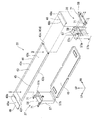
図4は、天板昇降式什器20を示す分解斜視図である。
図3、図4に示すように、天板昇降式什器20は、第1、第2の支持体31,32と、第1、第2の伸縮脚体34,35と、第1、第2の天板支持部(支持部)37,38と、配線支持部(配線トレー)41と、第一天板(天板)43と、第1、第2の軟質部材45,46と、一対の第二天板48とを備えている。
FIG. 4 is an exploded perspective view showing the top
As shown in FIG. 3 and FIG. 4, the top /
第1支持体31および第2支持体32は、左右方向に間隔をおいて、中央デスク脚部5および右デスク側板4にそれぞれ近接して配置されている。第1支持体31および第2支持体32は、床面F上に載置されている。
第1支持体31に第1伸縮脚体34が設けられている。第1伸縮脚体34は、第1支持体31から中央デスク脚部5に沿って上方へ向けて立ち上げられている。第1伸縮脚体34は、上端部が第1ブラケット51を介して連結部21に連結されている。すなわち、第1伸縮脚体34は、第1支持体31上に設けられて上下方向に延びている。
The
A first
第1伸縮脚体34は、横断面矩形に形成された多重管からなる支柱である。多重管とは、複数の管34a,34b,34cを入れ子にして構成された管をいう。複数の管34a,34b,34cは、横断面の形状が矩形である。なお、複数の管34a,34b,34cの横断面の形状は、矩形の他に、円形、楕円形、多角形等、様々な形状が可能である。
The 1st expansion-
第2支持体32に第2伸縮脚体35が設けられている。第2伸縮脚体35は、第2支持体32から右デスク側板4に沿って上方へ向けて立ち上げられている。第2伸縮脚体35は、上端部が第2ブラケット52を介して連結部21に連結されている。すなわち、第2伸縮脚体35は、第2支持体32上に設けられて上下方向に延びている。
第2伸縮脚体35は、第1伸縮脚体34と同様に、横断面矩形に形成された多重管からなる支柱である。複数の管35a,35b,35cは、横断面の形状が矩形である。なお、複数の管35a,35b,35cの横断面の形状は、矩形の他に、円形、楕円形、多角形等、様々な形状が可能である。
A second
Similar to the first
第1伸縮脚体34の複数の管34a,34b,34cと、第2伸縮脚体35の複数の管35a,35b,35cとは、操作スイッチ54の操作により伸縮する。操作スイッチ54は、第1デスク天板11の右前部11eに取り付けられている。
操作スイッチ54を操作することにより操作入力部55に信号が入力され、操作入力部55に入力された入力信号に基づいて駆動手段が動作する。操作入力部55は、第1デスク天板11の右端部11b近傍に取り付けられている。駆動手段は、第1伸縮脚体34内と第2伸縮脚体35内とに配設されている。駆動手段が動作することにより、第1伸縮脚体34の複数の管34a,34b,34cと、第2伸縮脚体35の複数の管35a,35b,35cと、が電動で上下に伸縮する。
これにより、第1伸縮脚体34と第2伸縮脚体35との上下方向の長さ寸法を調整することができる。
The plurality of
By operating the
Thereby, the length dimension of the up-down direction of the 1st expansion-
第1伸縮脚体34の管34cの上端部に、第1天板支持部37が取り付けられている。第2伸縮脚体35の管35cの上端部に、第2天板支持部38が取り付けられている。第1天板支持部37および第2天板支持部38は左右対称の部材であり、以下、第1天板支持部37および第2天板支持部38の各構成部材に同じ符号を付して、第2天板支持部38について詳しく説明する。
A first top
第2天板支持部38は、連結支持部57と、連結ブラケット58とを備えている。連結支持部57は、平面視U字状に折り曲げられ、U字状の内部に取付板59を有する。取付板59が第2伸縮脚体35の管35cの上端部に取り付けられている。連結支持部57の上端部57aに連結ブラケット58が取り付けられている。
第1伸縮脚体34の管34cの上端部に、第1天板支持部37が取り付けられている。第1天板支持部37は、第2天板支持部38と同様に、取付板(図示せず)を介して第1伸縮脚体34の管34cの上端部に取り付けられている。連結支持部57の上端部57aに連結ブラケット58が取り付けられている。
左右側の連結支持部57の下端片57bに配線支持部41が水平に架け渡された状態で取り付けられている。
The second top
A first top
The
図1に示すように、配線支持部41にテーブルタップ(電源タップ)61やLANポート(Local Area Network)(図示せず)等が載置されている。テーブルタップ61やLANポート等は、配線支持部41の上面に磁着されている。よって、テーブルタップ61やLANポート等は配線支持部41の上面に安定的に支持されている。
これにより、例えば、パーソナルコンピュータ62のコンセント63によるテーブルタップ61の差込口への差込、抜取作業を容易にできる。この結果、テーブルタップ61の使用時の使い勝手を良好なものとすることができる。
As shown in FIG. 1, a table tap (power supply tap) 61, a LAN port (Local Area Network) (not shown), and the like are placed on the
Thereby, for example, the insertion and extraction of the
また、LANポートの差込口へのLANケーブルの差込、抜取作業を容易にでき、LANポートの使用時の使い勝手を良好なものとすることができる。
さらに、配線支持部41の上面にテーブルタップ61やLANポートを磁着により支持することにより、天板昇降式什器システム1に市販のテーブルタップ61やLANポートを採用することが可能になる。よって、天板昇降式什器システム1に専用のテーブルタップやLANポートを備える必要がなく、天板昇降式什器システム1のコストを抑えることができる。
Also, the LAN cable can be easily inserted into and removed from the LAN port insertion port, and the usability when using the LAN port can be improved.
Furthermore, by supporting the
図3、図4に戻って、左右側の連結支持部57の各上端片57cに第一天板43が架け渡された状態に水平に取り付けられている。すなわち、第一天板43は、左右側の連結支持部57を介して第1伸縮脚体34および第2伸縮脚体35に支持されている。第一天板43は、什器空間23を上方から覆うように平面視矩形状に形成され、かつ、上面が平坦な作業面43aに形成されている。
第一天板43の後辺部43bには第1軟質部材45が取り付けられている。第一天板43の前辺部43cには、第2軟質部材46が取り付けられている。第1軟質部材45および第2軟質部材46は、例えば樹脂材やゴム材等で弾性変形可能に形成されている。
Returning to FIG. 3 and FIG. 4, the first
A first
第一天板43は、第1伸縮脚体34および第2伸縮脚体35を電動により上下に伸縮させることにより、第一天板43を下降位置P1(図2参照)と、上昇位置P2(図2参照)とに配置できる。
下降位置P1は、第一天板43の作業面43aが第1デスク天板11の上面11f(図1参照)や、第2デスク天板12の上面12e(図1参照)に対して面一に配置される位置である。
The first
In the lowered position P1, the
第2天板支持部38は、連結支持部57の上端部57aに連結ブラケット58が取り付けられている。連結ブラケット58は、上端部において前後方向の両端部に一対の支え片71を有する。一対の支え片71は、第一天板43から離れる方向に向けて側方(水平)に突出されている。一対の支え片71は、例えば、第二天板48を磁着可能に磁石を備えている。
一対の支え片71に第二天板48が上方から載置されている。第二天板48は、一対の支え片71に磁着可能に、例えば金属製の部材で、平面視矩形状に形成されている。一対の支え片71の磁石で第二天板48を磁着することにより、第二天板48を一対の支え片71で良好(確実)に支持することができる。
すなわち、第二天板48は、一対の支え片71(連結ブラケット58)および連結支持部57を介して、第2伸縮脚体35と第二天板48とに支持されている。
As for the 2nd top-
The second
That is, the second
また、一対の支え片71を第一天板43から離れる方向に向けて側方に突出させるだけの簡易的な構造でありながら、第二天板48を一対の支え片71で確実(良好)に支持することができる。
第二天板48は、平面視矩形状に形成され、上面48aが平坦に形成されている。第二天板48は、一対の支え片71に載置された状態において、上面48aが第一天板43の作業面43aに対して面一に配置される。また、第二天板48は、第一天板43の周縁部43dの右端部(一部)43eに対して端部48bが近接すると共に、上面(すなわち、作業面)48aが第一天板43の作業面43aと略同一面の作業面を形成する。
In addition, the second
The second
左側の第二天板48も、右側の第二天板48と同様に、第一天板43の周縁部43dの左端部(一部)43fに対して端部48bが近接すると共に、上面(すなわち、作業面)48aが第一天板43の作業面43aと略同一面の作業面を形成する。
よって、第一天板43の高さを第1伸縮脚体34および第2伸縮脚体35で変更させた状態において、例えば連結ブラケット58および連結支持部57(すなわち、第2天板支持部38)を執務者から隠すことができる。これにより、天板昇降式什器システム1としての体裁を良好なものとすることができる。
ここで、略同一面とは、第二天板48の作業面48aが第一天板43の作業面43aに対して平坦に配置された状態に加えて、さらに、第一天板43の作業面43aに対して、例えば第二天板48板厚寸法程度の段差が生じた状態も含むものとする。
Similarly to the right-side second
Therefore, in the state in which the height of the first
Here, “substantially the same surface” means that the
図1、図2に示すように、第一天板43を下降位置P1に配置することにより、第1デスク天板11、第2デスク天板12および第一天板43および第二天板48の全域を、大きな天板として使用することができる。
例えば、図1に示すように、第1デスク天板11の右半部、第2デスク天板12の右半部、第一天板43、および第二天板48の全域を面一にでき、全域を大きな天板として使用することができる。よって、例えば、第1デスク天板11の右半部、第2デスク天板12の右半部、第一天板43、および第二天板48の全域に大きな資料用紙78を広げることができる。
As shown in FIG. 1 and FIG. 2, the first
For example, as shown in FIG. 1, the right half of the first
一方、左側の天板昇降式什器20の第一天板43および第二天板48を上昇位置P2に配置することにより、第一天板43と第1デスク天板11との間や、第一天板43と第2デスク天板12との間に、配線支持部41へのアクセス空間75を形成できる。これにより、配線挿通作業を良好におこなうことができ、さらに、配線支持部41に配置したテーブルタップ61へのコンセント63の抜き差しや、LANポートへのLANケーブルの抜き差し等の作業性を良好にできる。
On the other hand, by disposing the first
また、第一天板43の後辺部43bに第1軟質部材45が取り付けられ、第一天板43の前辺部43cに第2軟質部材46が取り付けられている。
よって、第一天板43を下降位置P1に配置した際に、第一天板43の後辺部43bと第1デスク天板11との間を第1軟質部材45で塞いだ状態に保つことができる。この状態において、第1軟質部材45を弾性変形させて第一天板43の後辺部43bと第2デスク天板12との間に間隙部を確保できる。
同様に、第一天板43の前辺部43cと第2デスク天板12との間を第2軟質部材46で塞いだ状態に保つことができる。この状態において、第2軟質部材46を弾性変形させて第一天板43の前辺部43cと第2デスク天板12との間に間隙部を確保できる。
これにより、配線支持部41のテーブルタップ61に接続したコンセントのケーブルや、LANポートに接続したLANケーブルのケーブルを、第1デスク天板11の上面11fや第2デスク天板12の上面12eに引き出すことができる。
Further, the first
Therefore, when the first
Similarly, the state between the
Thereby, the cable of the outlet connected to the
さらに、第1軟質部材45や第2軟質部材46を弾性変形させることにより、第一天板43を下降位置P1に配置する際に、第一天板43と第1デスク天板11との間や、第一天板43と第2デスク天板12との間に配置された物品が挟まるのを防止することが出来る。これにより、天板昇降式什器システム1を使用する際の安全性を高めることができる。
また、第1軟質部材45や第2軟質部材46で間隙部を塞ぐことにより、第1デスク天板11上や第2デスク天板12上の物品が間隙部から什器空間23に落下することを防止できる。
Further, by elastically deforming the first
In addition, by closing the gap with the first
さらに、第一天板43が上昇位置P2に配置された状態において、配線支持部41が第1デスク天板11の上面11fや第2デスク天板12の上面12eに対して面一をなす位置に配置される。
よって、配線支持部41に配置したテーブルタップ61やLANポート等を、執務者10に一層近い位置に配置できる。これにより、配線挿通作業を一層良好におこなうことができ、さらに、配線支持部41に配置したテーブルタップ61へのコンセント63の抜き差しや、LANポートへのLANケーブルの抜き差し等の作業性を一層良好にできる。
Furthermore, the position where the
Therefore, the
図3、図4に示すように、例えば、第一天板43と共に第二天板48を下降位置P1(図2参照)に配置する際に、例えば、第二天板48と、隣接する第二天板48との間に物品がおかれ、第二天板48の下方方向から外力が加わることが考えられる。この場合に、一対の支え片71の磁着力に反して、第二天板48を外力で一対の支え片71から離して上方に移動させることができる。
よって、第二天板48と、隣接する第二天板48との間に配置された物品が挟まるのを防止することが出来る。これにより、天板昇降式什器システム1の使用時の安全性を高めることができる。
As shown in FIGS. 3 and 4, for example, when the second
Therefore, it is possible to prevent an article placed between the second
つぎに、第2実施形態の天板昇降式什器100を図5〜図7に基づいて説明する。
[第2実施形態]
図5は、本発明に係る第2実施形態の天板昇降式什器100を示す斜視図である。
図5に示すように、天板昇降式什器100は、第1、第2の支持体102,103と、第1、第2の伸縮脚体105,106と、第1、第2の天板支持部108,109(図6参照)と、一対の第一天板(天板)112と、一対の第二天板114とを備えている。
Below, the top-plate elevating
[Second Embodiment]
FIG. 5 is a perspective view showing the top
As shown in FIG. 5, the top /
一対の第1支持体102は、左側の第一天板112の下方において、左右方向に間隔をおいて配置されている。一対の第1支持体102は、床面F上に載置されている。一対の第1支持体102に第1伸縮脚体105が設けられている。第1伸縮脚体105は、第1支持体102から上方へ向けて立ち上げられている。すなわち、第1伸縮脚体105は、第1支持体102上に設けられて上下方向に延びている。一対の第1伸縮脚体105の上端部105aに、左側の第一天板112の左端部112aおよび右端部112bが支持されている。
第1伸縮脚体105は、横断面矩形に形成された多重管からなる支柱である。多重管の横断面の形状は、矩形の他に、円形、楕円形、多角形等、様々な形状が可能である。
The pair of
The 1st expansion-
一対の第2支持体103は、右側の第一天板112の下方において、左右方向に間隔をおいて配置されている。一対の第2支持体103は、床面F上に載置されている。一対の第2支持体103に第2伸縮脚体106が設けられている。第2伸縮脚体106は、第2支持体103から上方へ向けて立ち上げられている。すなわち、第2伸縮脚体106は、第2支持体103上に設けられて上下方向に延びている。一対の第2伸縮脚体106の上端部106aに、右側の第一天板112の左端部112aおよび右端部112bが支持されている。
第2伸縮脚体106は、第1伸縮脚体105と同様に、横断面矩形に形成された多重管からなる支柱である。多重管の横断面の形状は、矩形の他に、円形、楕円形、多角形等、様々な形状が可能である。
The pair of
Similar to the first
第1伸縮脚体105と第2伸縮脚体106とは、第1実施形態と同様に、電動で上下に伸縮する。第1伸縮脚体105と第2伸縮脚体106との上下方向の長さ寸法を調整することより、左右側の第一天板112が昇降する。
The first
図6は、天板昇降式什器100の要部を示す正面図である。
図6に示すように、左側の第一天板112に第1天板支持部(支持部)108を介して左側の第二天板114が支持されている。右側の第一天板112に第2天板支持部(支持部)109を介して右側の第二天板114が支持されている。
第1天板支持部108および第2天板支持部109は左右対称の部材であり、各構成部材に同じ符号を付して、第1天板支持部108について詳しく説明する。
FIG. 6 is a front view showing a main part of the top plate lifting
As shown in FIG. 6, the left second
The first top
第1天板支持部108は、枢軸121と、第1取付板122と、第2取付板123とを有する。第1取付板122の基端部および第2取付板123の基端部が枢軸121に回動自在に支持されている。すなわち、第1天板支持部108は、一例としてヒンジ部材が用いられている。
第1天板支持部108は、左側の第一天板112の右端部112bに第1取付板122が取り付けられている。また、第1天板支持部108は、左側の第二天板114の左端部114aに第2取付板123が取り付けられている。この状態において、枢軸121が上方に配置されている。よって、左側の第二天板114は、第1天板支持部108の枢軸121を軸にして左側の第一天板112に上方へ回動可能に支持されている。
The first top
The first top
第1天板支持部108によれば、第1取付板122および第2取付板123が当接した状態において、左側の第一天板112の作業面112cと左側の第二天板114の作業面114bとが略同一面に配置される。よって、左側の第一天板112の高さを第1、第2の伸縮脚体105,106(図5参照)で変更させた状態において、例えば第1天板支持部108を執務者から隠すことができる。これにより、天板昇降式什器100としての体裁を良好なものとすることができる。
また、第1天板支持部108を用いるだけの簡易的な構造で、左側の第二天板114を左側の第一天板112に確実に支持することができる。
According to the first top
In addition, the left second
図7は、天板昇降式什器100の第二天板114を上方に向けて移動させた状態を示す正面図である。
図7に示すように、例えば、左側の第一天板112と共に左側の第二天板114を下降位置P1に配置する際に、左側の第二天板114と、隣接する右側の第二天板114との間に物品がおかれることが考えられる。物品がおかれることにより、左側の第二天板114の下方方向から外力が加わることが考えられる。
この場合、左側の第二天板114を枢軸121を中心として上方に向けて移動させることができる。よって、左側の第二天板114と、隣接する右側の第二天板114との間に配置された物品が挟まるのを防止することが出来る。これにより、天板昇降式什器100の使用時の安全性を高めることができる。
FIG. 7 is a front view showing a state in which the second
As shown in FIG. 7, for example, when the left second
In this case, the left second
また、左側の第二天板114を枢軸121を中心として上方に移動させた状態において、左側の第二天板114を第1天板支持部108に連結した状態に保つことができる。よって、左側の第二天板114を上方に移動させる際に、第二天板114が紛失することを防止できる。これにより、天板昇降式什器100の使用時の利便性を高めることができる。
Further, in a state where the left second
以上、図面を参照して、本発明の実施形態を詳述してきたが、具体的な構成は、この実施形態に限らず、本発明の要旨を逸脱しない程度の設計的変更は、本発明に含まれる。
例えば、第1実施形態の天板昇降式什器システム1では、一対の支え片71に磁石を備えた例について説明したが、その他の例として一対の支え片71に磁石を備えない構成としてもよい。
この場合、一対の支え片71に第二天板48が上方から載置されることにより、第二天板48が一対の支え片71に支持される。よって、第1実施形態と同様に、一対の支え片71を第一天板43から離れる方向に向けて側方に突出させるだけの簡易的な構造でありながら、第二天板48を一対の支え片71で支持できる。
The embodiment of the present invention has been described in detail with reference to the drawings. However, the specific configuration is not limited to this embodiment, and design changes that do not depart from the gist of the present invention are not limited to the present invention. included.
For example, in the top plate lifting fixture system 1 of the first embodiment, the example in which the pair of
In this case, the second
1 天板昇降式什器システム
20,100 天板昇降式什器
31,32,102,103 第1、第2の支持体(支持体)
34,35,105,106 第1、第2の伸縮脚部(伸縮脚部)
37,38,108,109 第1、第2の天板支持部(支持部)
43,112 第一天板(天板)
43a,112c 第一天板の作業面(上面)
43d 第一天板の周縁部
43e 第一天板の周縁部の右端部(一部)
43f 第一天板の周縁部の左端部(一部)
48,114 第二天板
48a,114b 第二天板の作業面(上面)
48b 第二天板の端部
112b 第一天板の右端部(第一天板の周縁部の一部)
114a 第二天板の左端部(第二天板の端部)
121 枢軸
F 床面
DESCRIPTION OF SYMBOLS 1 Top plate raising / lowering fixture system 20,100 Top plate raising / lowering
34, 35, 105, 106 First and second telescopic legs (extensible legs)
37, 38, 108, 109 First and second top plate support portions (support portions)
43,112 First top plate (top plate)
43a, 112c Work surface (upper surface) of the first top plate
43d The peripheral part of the first
43f Left end portion (part) of first peripheral edge
48, 114 Second
48b End of the
114a Left end of second top plate (end of second top plate)
121 Axis F Floor
Claims (4)
前記天板に支持部を介して支持され、前記天板の周縁部の一部において、前記天板の周縁部に端部が近接すると共に、前記天板の作業面と略同一面の作業面を形成する第二天板を備え、
前記第二天板は、前記天板の高さを変更させることによって前記天板の下方方向から外力が加わった際に、前記天板より上方に移動可能としたことを特徴とする天板昇降式什器。 A support body placed on the floor, an extendable leg body provided on the support body and extending in the vertical direction and adjustable in length in the vertical direction; A top plate liftable fixture having a top plate on which is formed,
A work surface that is supported by the top plate via a support portion and that is close to the work surface of the top plate and has an end close to the peripheral portion of the top plate in a part of the peripheral portion of the top plate A second top plate forming
The second top plate can be moved upward from the top plate when an external force is applied from below the top plate by changing the height of the top plate. Formula furniture.
前記支持部に前記第二天板が載置されていることを特徴とする請求項1に記載の天板昇降式什器。 The support portion is provided to protrude sideways in a direction away from the top plate,
The tabletop lifting fixture according to claim 1, wherein the second top plate is placed on the support portion.
Priority Applications (1)
| Application Number | Priority Date | Filing Date | Title |
|---|---|---|---|
| JP2018050024A JP7125271B2 (en) | 2018-03-16 | 2018-03-16 | Top plate lifting type fixtures |
Applications Claiming Priority (1)
| Application Number | Priority Date | Filing Date | Title |
|---|---|---|---|
| JP2018050024A JP7125271B2 (en) | 2018-03-16 | 2018-03-16 | Top plate lifting type fixtures |
Publications (2)
| Publication Number | Publication Date |
|---|---|
| JP2019155012A true JP2019155012A (en) | 2019-09-19 |
| JP7125271B2 JP7125271B2 (en) | 2022-08-24 |
Family
ID=67995480
Family Applications (1)
| Application Number | Title | Priority Date | Filing Date |
|---|---|---|---|
| JP2018050024A Active JP7125271B2 (en) | 2018-03-16 | 2018-03-16 | Top plate lifting type fixtures |
Country Status (1)
| Country | Link |
|---|---|
| JP (1) | JP7125271B2 (en) |
Cited By (2)
| Publication number | Priority date | Publication date | Assignee | Title |
|---|---|---|---|---|
| CN112716202A (en) * | 2020-12-18 | 2021-04-30 | 丽水市美芦装饰设计有限公司 | Multifunctional table suitable for children |
| CN115798355A (en) * | 2022-12-25 | 2023-03-14 | 扬州工业职业技术学院 | An assembled steel structure bracket |
Citations (7)
| Publication number | Priority date | Publication date | Assignee | Title |
|---|---|---|---|---|
| JPS5833953U (en) * | 1981-08-28 | 1983-03-05 | シャープ株式会社 | Yagura Kotatsu |
| JPS6029551U (en) * | 1983-08-04 | 1985-02-28 | 株式会社 ニット−製作所 | Lifting counter for financial institutions |
| JPS60100905A (en) * | 1983-11-08 | 1985-06-04 | 松下電器産業株式会社 | Table |
| DE8710445U1 (en) * | 1987-07-30 | 1987-09-17 | Hebbel, Dierk, 7151 Allmersbach | Combination table |
| JP2002306250A (en) * | 2001-04-11 | 2002-10-22 | Yusaku Kanbara | Escape table |
| CN104257104A (en) * | 2013-12-25 | 2015-01-07 | 南宁市磁汇科技有限公司 | Lifting computer office table |
| JP3207307U (en) * | 2016-03-22 | 2016-11-04 | 耀全 呉 | Elevating folding desk |
-
2018
- 2018-03-16 JP JP2018050024A patent/JP7125271B2/en active Active
Patent Citations (7)
| Publication number | Priority date | Publication date | Assignee | Title |
|---|---|---|---|---|
| JPS5833953U (en) * | 1981-08-28 | 1983-03-05 | シャープ株式会社 | Yagura Kotatsu |
| JPS6029551U (en) * | 1983-08-04 | 1985-02-28 | 株式会社 ニット−製作所 | Lifting counter for financial institutions |
| JPS60100905A (en) * | 1983-11-08 | 1985-06-04 | 松下電器産業株式会社 | Table |
| DE8710445U1 (en) * | 1987-07-30 | 1987-09-17 | Hebbel, Dierk, 7151 Allmersbach | Combination table |
| JP2002306250A (en) * | 2001-04-11 | 2002-10-22 | Yusaku Kanbara | Escape table |
| CN104257104A (en) * | 2013-12-25 | 2015-01-07 | 南宁市磁汇科技有限公司 | Lifting computer office table |
| JP3207307U (en) * | 2016-03-22 | 2016-11-04 | 耀全 呉 | Elevating folding desk |
Cited By (3)
| Publication number | Priority date | Publication date | Assignee | Title |
|---|---|---|---|---|
| CN112716202A (en) * | 2020-12-18 | 2021-04-30 | 丽水市美芦装饰设计有限公司 | Multifunctional table suitable for children |
| CN112716202B (en) * | 2020-12-18 | 2023-01-03 | 丽水市美芦装饰设计有限公司 | Multifunctional table suitable for children |
| CN115798355A (en) * | 2022-12-25 | 2023-03-14 | 扬州工业职业技术学院 | An assembled steel structure bracket |
Also Published As
| Publication number | Publication date |
|---|---|
| JP7125271B2 (en) | 2022-08-24 |
Similar Documents
| Publication | Publication Date | Title |
|---|---|---|
| JP6566552B2 (en) | Furniture with a top plate | |
| WO2016175241A1 (en) | Top-panel-equipped furniture and furniture system | |
| JP2019155012A (en) | Top plate ascending and descending fixture | |
| JP6675857B2 (en) | Furniture with top plate | |
| JP2018068948A (en) | Lifting fixture | |
| JP2019136201A (en) | Top plate lifting/lowering furniture | |
| JP6692143B2 (en) | Storage box suspension structure | |
| JPH08131851A (en) | Laboratory table | |
| KR102118686B1 (en) | clamp | |
| JP3790836B2 (en) | Support device | |
| JP6641621B2 (en) | Top plate lifting fixtures | |
| JP7697856B2 (en) | Fixtures System | |
| JP6327599B2 (en) | Table system | |
| JP2005342377A (en) | Desk having bookshelf | |
| JP6795949B2 (en) | table | |
| JP4943041B2 (en) | Panel mounting structure to the top table | |
| JP7623259B2 (en) | Fixtures System | |
| JP7471050B2 (en) | Lift table | |
| JP2018068950A (en) | Furniture with a top plate | |
| JP4782567B2 (en) | Mounting structure of shelf board to partition panel | |
| JP6995567B2 (en) | Top plate elevating furniture | |
| JP6916709B2 (en) | Furniture system | |
| KR102235203B1 (en) | A shelf for desks used at internet cafe | |
| JP2011101703A (en) | Desk | |
| JP2025068295A (en) | Furniture fixture and furniture fixture unit |
Legal Events
| Date | Code | Title | Description |
|---|---|---|---|
| A621 | Written request for application examination |
Free format text: JAPANESE INTERMEDIATE CODE: A621 Effective date: 20210303 |
|
| A977 | Report on retrieval |
Free format text: JAPANESE INTERMEDIATE CODE: A971007 Effective date: 20220117 |
|
| A131 | Notification of reasons for refusal |
Free format text: JAPANESE INTERMEDIATE CODE: A131 Effective date: 20220118 |
|
| A521 | Request for written amendment filed |
Free format text: JAPANESE INTERMEDIATE CODE: A523 Effective date: 20220318 |
|
| TRDD | Decision of grant or rejection written | ||
| A01 | Written decision to grant a patent or to grant a registration (utility model) |
Free format text: JAPANESE INTERMEDIATE CODE: A01 Effective date: 20220712 |
|
| A61 | First payment of annual fees (during grant procedure) |
Free format text: JAPANESE INTERMEDIATE CODE: A61 Effective date: 20220812 |
|
| R150 | Certificate of patent or registration of utility model |
Ref document number: 7125271 Country of ref document: JP Free format text: JAPANESE INTERMEDIATE CODE: R150 |
|
| R250 | Receipt of annual fees |
Free format text: JAPANESE INTERMEDIATE CODE: R250 |