JP2019167166A - Winch control method and winch system using the same - Google Patents
Winch control method and winch system using the same Download PDFInfo
- Publication number
- JP2019167166A JP2019167166A JP2018053706A JP2018053706A JP2019167166A JP 2019167166 A JP2019167166 A JP 2019167166A JP 2018053706 A JP2018053706 A JP 2018053706A JP 2018053706 A JP2018053706 A JP 2018053706A JP 2019167166 A JP2019167166 A JP 2019167166A
- Authority
- JP
- Japan
- Prior art keywords
- winch
- suspended load
- height
- suspended
- detection means
- Prior art date
- Legal status (The legal status is an assumption and is not a legal conclusion. Google has not performed a legal analysis and makes no representation as to the accuracy of the status listed.)
- Pending
Links
- 238000000034 method Methods 0.000 title claims description 11
- 238000001514 detection method Methods 0.000 claims abstract description 43
- 239000012209 synthetic fiber Substances 0.000 claims abstract description 29
- 229920002994 synthetic fiber Polymers 0.000 claims abstract description 29
- 238000004804 winding Methods 0.000 claims abstract description 23
- 230000007935 neutral effect Effects 0.000 claims abstract description 12
- 239000000725 suspension Substances 0.000 claims description 12
- 238000012423 maintenance Methods 0.000 description 8
- 238000010276 construction Methods 0.000 description 3
- 230000007423 decrease Effects 0.000 description 3
- 238000010586 diagram Methods 0.000 description 2
- 239000003638 chemical reducing agent Substances 0.000 description 1
- 238000004891 communication Methods 0.000 description 1
- 230000005484 gravity Effects 0.000 description 1
- 238000009940 knitting Methods 0.000 description 1
- 239000000463 material Substances 0.000 description 1
Images
Landscapes
- Control And Safety Of Cranes (AREA)
Abstract
Description
本発明は、合成繊維ロープ使用により発生する「時間経過に伴う吊荷の降下」を自動巻上げ補償するウインチシステムに関する。 The present invention relates to a winch system that automatically compensates for a "fall of suspended load with time" generated by using a synthetic fiber rope.
ワイヤロープと同等の強度を有しながらも単位長さ当たりの重量が小さく装置の軽量化に役立つことから、クレーンのウインチの吊荷用ロープとして合成繊維ロープの使用が検討されるようになってきた。 Although it has the same strength as a wire rope but has a small weight per unit length, which helps to reduce the weight of the equipment, the use of synthetic fiber ropes as a hoisting rope for crane winches has been considered. It was.
ところが、吊荷が宙吊りの状態でウインチドラムの回転を停止させたような張力がかかったままの状態では、合成繊維ロープでは伸びやウインチドラムでの食込み、潰れが発生する。そのため、吊荷が降下してしまい、吊荷の降下が止まるまで安定するのに時間がかかるという現象が指摘されている。 However, in a state where the suspended load is suspended in a suspended state and tension is applied to stop the rotation of the winch drum, the synthetic fiber rope is stretched, bitten by the winch drum, and crushed. For this reason, it has been pointed out that the suspended load falls and it takes time to stabilize until the suspended load stops.
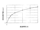
図5は、出願人が計測した「合成繊維ロープにおける経過時間と吊荷の降下量との関係」を示すグラフである。図5から分かるように、宙吊りにされた吊荷は初期に急速に降下したあと徐々に時間当たりの降下量が減少しつつも時間の経過とともに降下していき、数分間で数十mm降下する。なお、図5に示したグラフは、合成繊維ロープの特性の一例を示すものであって、合成繊維ロープの材質、編み方、長さ、直径、張力、温度、湿度、ウインチドラムでの巻層数、等により特性は大きく変化する。 FIG. 5 is a graph showing the “relationship between the elapsed time in the synthetic fiber rope and the amount of descent of the suspended load” measured by the applicant. As can be seen from FIG. 5, the suspended load suspended in the air rapidly descends in the initial stage and then gradually decreases with the passage of time, while the amount of descent per hour gradually decreases, and falls several tens of millimeters in several minutes. . The graph shown in FIG. 5 shows an example of the characteristics of the synthetic fiber rope, and the synthetic fiber rope material, knitting method, length, diameter, tension, temperature, humidity, winding layer in the winch drum The characteristics vary greatly depending on the number and the like.
このように、合成繊維ロープには吊荷降下現象が発生するため、吊荷が宙吊り状態でウインチドラムを停止させてからのクレーン作業である、ボルト通しにおける吊荷の位置合わせが困難となってしまう。 As described above, since the suspended load drop phenomenon occurs in the synthetic fiber rope, it is difficult to align the suspended load in the bolt thread, which is a crane work after the winch drum is stopped in the suspended state. End up.
ところで、かご及び釣合重りを吊り下げる主索に合成繊維ロープを用いるエレベータにおいて、駆動シーブとそらせ車との間に移動可能な調整シーブを備えた、主索の伸び補償装置が提案されている(特許文献1)。特許文献1に記載された伸び補償装置によって合成繊維ロープに発生する伸びを補償することにより、主索の長さの変化に対応してかご及び釣合重りの位置関係を適正に保つことができる。 By the way, in an elevator using a synthetic fiber rope for a main rope for suspending a car and a counterweight, a main rope elongation compensation device having an adjustment sheave movable between a drive sheave and a deflector is proposed. (Patent Document 1). By compensating for the elongation generated in the synthetic fiber rope by the elongation compensator described in Patent Document 1, it is possible to properly maintain the positional relationship between the car and the balance weight in accordance with the change in the length of the main rope. .
しかし、クレーンのウインチには釣合重りが存在しないし、吊荷用ロープをウインチドラムに巻き取るようになっている、などエレベータとは全体構成が全く異なるため、特許文献1に記載された伸び補償装置を適用することができない。 However, the crane winch does not have a counterweight, and the entire configuration is completely different from an elevator, such as winding a hoisting rope around a winch drum. The compensation device cannot be applied.
そこで、本発明は、クレーン操縦者がウインチの操作レバーを中立に戻した以降は、宙吊り状態の吊荷の検出した高さ信号に基づきウインチドラムによる巻取り駆動をフィードバック制御し吊荷降下を補償することで、吊荷高さを一定に保つことができるウインチ制御方法、及び同方法を用いたウインチシステムを提案する。 Therefore, after the crane operator returns the winch control lever to the neutral position, the present invention compensates the suspended load by feedback control of the winding drive by the winch drum based on the height signal detected by the suspended suspended load. Thus, a winch control method capable of keeping the suspended load height constant and a winch system using the same method are proposed.
第1の発明のウインチ制御方法は、合成繊維ロープを使用するウインチの制御方法であって、宙吊り状態の吊荷の高さを検出し、当該検出信号を用いて前記ウインチの巻取り駆動をフィードバック制御することによって、前記吊荷を同じ高さに維持することを特徴とする。 A winch control method according to a first aspect of the present invention is a winch control method using a synthetic fiber rope, which detects the height of a suspended load in a suspended state and feeds back the winch winding drive using the detection signal. The suspended load is maintained at the same height by controlling.
第1の発明のウインチ制御方法は、吊荷高さ信号に基づきウインチの巻取り駆動をフィードバック制御することにより、合成繊維ロープ使用により発生する「時間経過に伴う吊荷の降下」を自動巻上げ補償することができる。すなわち、宙吊り状態の吊荷を同じ高さに維持しておける。 The winch control method according to the first aspect of the invention automatically compensates for the "lift of suspended load over time" generated by using a synthetic fiber rope by performing feedback control of the winch winding drive based on the suspended load height signal. can do. That is, the suspended load in the suspended state can be maintained at the same height.
第2の発明のウインチシステムは、合成繊維ロープを使用するウインチシステムであって、ウインチ操作レバーと、吊荷の重さを検出する吊荷重さ検出手段と、前記吊荷の高さを検出する吊荷高さ検出手段と、前記合成繊維ロープを巻き取り・巻き戻しするウインチ手段と、前記ウインチ操作レバーの操作信号と前記吊荷重さ検出手段及び前記吊荷高さ検出手段からの検出信号が入力され前記ウインチ手段に駆動信号を出力するコントローラと、を備え、前記コントローラは、前記ウインチ操作レバーからの操作信号及び前記吊荷重さ検出手段からの検出信号により前記吊荷が宙吊り状態で前記ウインチ操作レバーが中立に戻されたことを判断すると、前記吊荷を同じ高さに維持するよう前記吊荷高さ検出手段からの検出信号を用いて前記ウインチ手段による巻取り駆動をフィードバック制御することを特徴とする。 A winch system according to a second aspect of the invention is a winch system using a synthetic fiber rope, the winch operation lever, a suspension load detection means for detecting the weight of the suspension load, and the height of the suspension load. Suspended load height detection means, winch means for winding and unwinding the synthetic fiber rope, operation signals of the winch operation lever, detection signals from the suspended load detection means and the suspended load height detection means And a controller that outputs a drive signal to the winch means, and the controller winches the suspension load when the suspension load is suspended by an operation signal from the winch operation lever and a detection signal from the suspension load detection means. When it is determined that the operation lever has been returned to the neutral position, a detection signal from the suspended load height detecting means is used to maintain the suspended load at the same height. Wherein the feedback control of the winding drive by wrench means.
第2の発明のウインチシステムは、コントローラが吊荷を同じ高さに維持するよう吊荷高さ検出手段からの検出信号を用いてウインチ手段による巻取り駆動をフィードバック制御するので合成繊維ロープ使用により発生する「時間経過に伴う吊荷の降下」を自動巻上げ補償し、宙吊り状態の吊荷を同じ高さに維持しておける。そのため、建て方作業におけるボルト合わせのようなクレーン作業において、吊荷の高さ方向の位置合わせが安全かつ効率的に行える。 In the winch system of the second invention, the controller controls the winding drive by the winch means using the detection signal from the suspended load height detecting means so that the suspended load is maintained at the same height. It can automatically compensate for the “falling of the suspended load over time” that occurs and keep the suspended load at the same height. Therefore, in the crane work such as bolt alignment in the construction work, the suspended load can be positioned in the height direction safely and efficiently.
第3の発明のウインチシステムは、前記ウインチ手段は、油圧式ウインチであることを特徴とする。 The winch system according to a third aspect of the invention is characterized in that the winch means is a hydraulic winch.
移動式クレーンに多く使用される油圧式ウインチに合成繊維ロープを使用した場合にも、吊荷が宙吊り状態でウインチ操作レバーを中立に戻した以降において同じ吊荷高さを維持することができる。 Even when a synthetic fiber rope is used for a hydraulic winch often used for a mobile crane, the same suspended load height can be maintained after the winch operating lever is returned to neutral while the suspended load is suspended in the air.
第4の発明のウインチシステムは、前記吊荷高さ検出手段は、非接触型の距離センサーを用いたものであることを特徴とする。 The winch system according to a fourth aspect of the invention is characterized in that the suspended load height detecting means uses a non-contact type distance sensor.
第4の発明のウインチシステムは、非接触型の距離センサーを用いることにより、屋外作業が多い移動式クレーンなどにも本発明のウインチシステムを適用することができる。 The winch system according to the fourth aspect of the invention can be applied to a mobile crane or the like having a lot of outdoor work by using a non-contact type distance sensor.
本発明のウインチ制御方法又はウインチシステムによれば、合成繊維ロープを使用していても、クレーン操縦者がウインチの操作レバーを中立に戻した以降は、宙吊り状態の吊荷の検出した高さ信号に基づきウインチドラムによる巻取り駆動をフィードバック制御し吊荷降下を補償することで、吊荷高さを一定に保つことができる。そのため、建て方作業におけるボルト合わせのようなクレーン作業において、吊荷の高さ方向の位置合わせが安全かつ効率的に行える。 According to the winch control method or winch system of the present invention, even if a synthetic fiber rope is used, after the crane operator returns the operation lever of the winch to neutral, the height signal detected by the suspended load in the suspended state is detected. Based on the above, the height of the suspended load can be kept constant by feedback controlling the winding drive by the winch drum and compensating for the suspended load drop. Therefore, in the crane work such as bolt alignment in the construction work, the suspended load can be positioned in the height direction safely and efficiently.
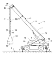
図1は、本発明のウインチシステムを搭載したラフテレーンクレーン1である。ラフテレーンクレーン1は、アウトリガ2を地面3に接地したのち伸縮ブーム4を起仰かつ伸長させたクレーン作業姿勢となっている。図1に示したラフテレーンクレーン1には合成繊維ロープ7を吊荷用ロープとして使用するウインチシステムが搭載されている。旋回フレーム5には合成繊維ロープ7を巻き取り・巻き戻しするウインチ手段8が搭載されている。旋回フレーム5に配置された運転室10内にはウインチ操作レバー11が配置されている。
FIG. 1 is a rough terrain crane 1 equipped with the winch system of the present invention. The rough terrain crane 1 is in a crane working posture in which the
図1に示すように、ウインチ手段8のウインチドラム12から繰り出された合成繊維ロープ7は、伸縮ブーム4の背面部13を経由してブームヘッド14から吊り下げられる。さらに合成繊維ロープ7は、吊荷用フック15のシーブ16及びブームヘッド14のシーブ17に必要回数掛け回されたのち、ブームヘッド14又は吊荷用フック15にその端部を係止される。図1に示した吊荷用フック15には玉掛けワイヤ18を介して吊荷20が宙吊り状態で吊り下げられている。
As shown in FIG. 1, the
ブームヘッド14には、吊荷高さ検出手段20を構成する非接触型の距離センサー21が吊下げられている。距離センサー21として具体的には、超音波を用いるセンサー、レーザーを用いるセンサーなどが使用される。距離センサー21から吊荷用フック15の上面の反射板22に対し超音波23又はレーザー24を照射し、反射して返ってくるまでの時間を計測し、その距離を計測する。この場合、正確には吊荷用フック15の高さを検出している。吊荷20と吊荷用フック15を連絡する玉掛けワイヤ18の伸びは無視し得るので、本発明では吊荷高さを制御対象としているが、吊荷用フック15の高さを検出することで吊荷高さを制御することが可能である。
A non-contact
旋回フレーム5と伸縮ブーム4との間に介装される起伏シリンダ25には、吊荷重さ検出手段26を構成する起伏シリンダ軸力センサーが配置されている。その起伏シリンダ軸力センサーは、起伏シリンダ25に作用する軸力を検出する。吊荷重さ検出手段26は、検出した起伏シリンダ軸力および伸縮ブーム4の長さ・起伏角度から吊荷20の重さを演算する。
In the hoisting
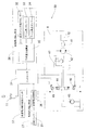
図2は、本発明の実施の形態に係るウインチシステム30のブロック図である。コントローラ31には、ウインチ操作レバー11(図1参照)からの操作信号が入力される。具体的には、ウインチ操作レバー11の操作方向(巻上げ、巻下げ)と操作量(巻き上げ下げ速度)の操作信号がコントローラ31に入力される。
FIG. 2 is a block diagram of the
コントローラ31には、吊荷重さ検出手段26からの検出信号が入力される。吊荷重さ検出手段26は、起伏シリンダ軸力センサー32、ブーム長さセンサー33、ブーム角度センサー34、吊荷重さ演算部35から構成されている。起伏シリンダ軸力センサー32としては、具体的には、起伏シリンダ25(図1参照)の保持側油室に設けられる油圧センサーあるいは、ロッドに設けられるロードセルが使用される。ブーム長さセンサー33としては、具体的には、伸縮ブーム4(図1参照)の基端部と先端部とを連絡して配置されるコードリール式長さ検出器などが使用される。ブーム角度センサー34としては、具体的には、旋回フレーム5の伸縮ブーム4枢支部(図1参照)に配置され両者の相対角度を検出するポテンショメーターなどが使用される。
A detection signal from the suspended load detection means 26 is input to the
起伏シリンダ軸力センサー32、ブーム長さセンサー33、ブーム角度センサー34の検出信号は、吊荷重さ演算部35に入力される。吊荷重さ演算部35は、伸縮ブーム4各部の重量重心データを記憶している。吊荷重さ演算部35は、入力信号及び記憶データから吊荷(図1参照)の重さを演算し、コントローラ31に出力する。
Detection signals from the hoisting cylinder axial force sensor 32, the boom length sensor 33, and the
吊荷高さ検出手段27は、距離センサー21(図1参照)、吊荷高さ演算部36から構成されている。距離センサー21からの検出信号が吊荷高さ演算部36に入力され、吊荷高さ演算部36は吊荷用フック15又は吊荷20の高さを演算する。コントローラ31には、吊荷高さ検出手段27からの検出信号が入力される。吊荷高さ維持制御スイッチ37は、吊荷高さ維持制御を行うか行わないかを選択するスイッチで、運転室10(図面1参照)内のウインチ操作レバー11の近傍に配置されている。吊荷高さ維持制御スイッチ37の操作信号はコントローラ31に入力される。
The suspended load height detection means 27 includes the distance sensor 21 (see FIG. 1) and the suspended load
ウインチ手段8では、合成繊維ロープが巻き取られるウインチドラム12が減速機41を介して油圧モーター42によって回転駆動される。油圧モーター42には、油圧ポンプ43から吐出された圧油がパイロット式切換弁44によって方向と流量を切り換え制御され供給される。巻上げ側電磁比例弁45は、コントローラ31からの巻上げ駆動信号に応じたパイロット圧を生成し、パイロット式切換弁44に供給する。巻下げ側電磁比例弁46は、コントローラ31からの巻下げ駆動信号に応じたパイロット圧を生成し、パイロット式切換弁44に供給する。パイロット式切換弁44は、コントローラ31からの駆動信号に応じた方向と流量に圧油を切り換え油圧モーター42に供給する。なお、油圧モーター42への供給油路にはカウンタバランス弁47が介装されている。
In the winch means 8, the
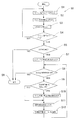
図3に図2に示したウインチシステム30の制御フローチャート50を示す。ウインチ操作レバー11(図2参照)からコントローラ31にウインチ操作レバー信号が入力される(ステップ1)。コントローラ31からウインチ手段8にウインチ駆動信号が出力される(ステップ2)。吊荷重さ検出手段26からコントローラ31に吊荷重さ信号が入力される(ステップ3)。以上は、通常のウインチ操作のフローチャートである。
FIG. 3 shows a
次に、ウインチ操作レバー11(図2参照)が中立かどうか判定される(ステップ4)。中立でない場合は、通常のウインチ操作のフローチャートが継続される。中立の場合は、ウインチ操作が停止されたと判断され、吊荷重さの変化が判定される(ステップ5)。吊荷重さが同じでない場合、すなわち宙吊りだった吊荷20(図1参照)が接地された場合はウインチシステム30の制御が終了する(ステップ6)。吊荷重さが同じ場合、すなわち吊荷20が宙吊り状態でウインチ操作が停止した場合は、吊荷高さ検出手段27(図2参照)からレバー中立直後吊荷高さHsがコントローラ31に入力される(ステップ7)。
Next, it is determined whether or not the winch operation lever 11 (see FIG. 2) is neutral (step 4). If not neutral, the normal winch operation flowchart is continued. If neutral, it is determined that the winch operation has been stopped, and a change in the suspended load is determined (step 5). When the suspended loads are not the same, that is, when the suspended load 20 (see FIG. 1) that is suspended in the air is grounded, the control of the
次に、吊荷高さ維持制御スイッチ37からの信号がONかどうか判定される(ステップ8)。吊荷高さ維持制御がOFFの場合は、ウインチシステム30の制御が終了する(ステップ6)。吊荷高さ維持制御がONの場合は、吊荷降下量Hdが閾値よりも大きいかどうかが判定される(ステップS9)。吊荷降下量Hdが閾値よりも大きい場合は、コントローラ31からウインチ手段8に対してウインチ微少巻上げ駆動信号が出力される(S10)。吊荷降下量Hdが閾値よりも小さい場合は、コントローラ31からウインチ手段8に対してウインチ微少巻上げ駆動信号が出力されることなく、次のステップに移行する。
Next, it is determined whether or not the signal from the suspended load height
次に、制御時吊荷高さHcが、吊荷高さ検出手段27(図2参照)からコントローラ31に入力される(ステップ11)。吊荷降下量Hd(Hd=Hs―Hc)がコントローラ31で演算される(ステップ12)。以降、吊荷20(図1参照)を同じ高さに維持するよう吊荷高さ検出手段27からの検出信号を用いてウインチ手段8による巻取り駆動するフィードバック制御(ステップ8〜ステップ12で示される)が繰り返される。
Next, the suspended load height Hc is input from the suspended load height detection means 27 (see FIG. 2) to the controller 31 (step 11). The suspended load drop amount Hd (Hd = Hs−Hc) is calculated by the controller 31 (step 12). Thereafter, feedback control (indicated by
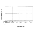
図4は、実施の形態に係るウインチシステム30による吊荷高さ維持制御の一例を示すグラフである。吊荷20が宙吊り状態(図1参照)でウインチ操作レバー11(図2参照)が中立位置に戻された時から、吊荷高さ維持制御がスタートする。図4に示した制御例では、制御の閾値がΔZmmに設定されている。図4に示されるように、吊荷降下量HdがΔZmmに達すると、吊荷の降下量Hdが0mmとなるよう合成繊維ロープ7がウインチ手段8によって微少量巻き上げられる。この微少巻上げが繰り返されることにより、吊荷20(図1参照)が同じ高さに維持される。なお、本発明のウインチ制御は、図4に示した例に限定されない。宙吊り状態の吊荷の検出した高さ信号に基づきウインチドラムによる巻取り駆動をフィードバック制御するものであればどのような制御内容であっても採用可能である。
FIG. 4 is a graph showing an example of the suspended load height maintenance control by the
図5に示すように、合成繊維ロープ7を用いたウインチシステム30の吊荷降下量は、時間の経過とともに単位時間当たりの吊荷降下量が減少する特性を有している。そのため、本発明のウインチシステム30での巻上げは、経過時間とともに作動のインターバル時間が長くなる傾向となる。なお、本発明の吊荷高さ維持のフィードバック制御の閾値の設定にあたっては、各種の制御ファクターが考慮される。例えば、油圧供給系(油圧ポンプ43、パイロット切換弁44)の1回に供給可能な最小油量、油圧モーター42の可能な最小回転角度、吊荷高さ検出手段27の検出高さ分解能などが考慮され、総合的に適切な閾値が設定される。なお、その際にはボルト合わせ等のクレーン作業時において許容される吊荷高さの変化程度も考慮される。
As shown in FIG. 5, the suspended load drop of the
以上、本発明のウインチ制御方法又はウインチシステム30によれば、合成繊維ロープを使用していても、クレーン操縦者がウインチ操作レバー11を中立に戻した以降は、宙吊り状態の吊荷の検出した高さ信号に基づきウインチドラムによる巻取り駆動をフィードバック制御し吊荷降下を補償することで、吊荷高さを一定に保つことができる。そのため、建て方作業におけるボルト合わせのようなクレーン作業において、吊荷の高さ方向の位置合わせが安全かつ効率的に行える。
As described above, according to the winch control method or the
7:合成繊維ロープ
8:ウインチ手段
11:ウインチ操作レバー
20:吊荷
21:距離センサー
26:吊荷重さ検出手段
27:吊荷高さ検出手段
30:ウインチシステム
31:コントローラ
7: synthetic fiber rope 8: winch means 11: winch operation lever 20: suspended load 21: distance sensor 26: suspended load detection means 27: suspended load height detection means 30: winch system 31: controller
Claims (4)
宙吊り状態の吊荷の高さを検出し、当該検出信号を用いて前記ウインチの巻取り駆動をフィードバック制御することによって、前記吊荷を同じ高さに維持することを特徴とするウインチ制御方法。 A method for controlling a winch using a synthetic rope,
A winch control method characterized by maintaining the suspended load at the same height by detecting the height of the suspended load in the suspended state and performing feedback control of the winding drive of the winch using the detection signal.
ウインチ操作レバーと、
吊荷の重さを検出する吊荷重さ検出手段と、
前記吊荷の高さを検出する吊荷高さ検出手段と、
前記合成繊維ロープを巻き取り・巻き戻しするウインチ手段と、
前記ウインチ操作レバーからの操作信号と前記吊荷重さ検出手段及び前記吊荷高さ検出手段からの検出信号が入力され前記ウインチ手段に駆動信号を出力するコントローラと、を備え、
前記コントローラは、前記ウインチ操作レバーからの操作信号及び前記吊荷重さ検出手段からの検出信号により前記吊荷が宙吊り状態で前記ウインチ操作レバーが中立に戻されたことを判断すると、前記吊荷を同じ高さに維持するよう前記吊荷高さ検出手段からの検出信号を用いて前記ウインチ手段による巻取り駆動をフィードバック制御することを特徴とするウインチシステム。 A winch system using synthetic rope,
Winch control lever,
A suspended load detection means for detecting the weight of the suspended load;
A suspended load height detecting means for detecting the height of the suspended load;
Winch means for winding and unwinding the synthetic fiber rope;
A controller that receives an operation signal from the winch operation lever, a detection signal from the suspension load detection means and a detection signal from the suspension load height detection means, and outputs a drive signal to the winch means,
When the controller determines that the winch operation lever has been returned to neutral in the suspended state by the operation signal from the winch operation lever and the detection signal from the suspension load detection means, the controller removes the suspended load. A winch system in which a winding drive by the winch means is feedback-controlled using a detection signal from the suspended load height detection means so as to maintain the same height.
請求項2に記載されたウインチシステム。 The winch means is a hydraulic winch,
The winch system according to claim 2.
請求項2又は3に記載されたウインチシステム。
The suspended load height detecting means uses a non-contact type distance sensor,
The winch system according to claim 2 or 3.
Priority Applications (1)
| Application Number | Priority Date | Filing Date | Title |
|---|---|---|---|
| JP2018053706A JP2019167166A (en) | 2018-03-22 | 2018-03-22 | Winch control method and winch system using the same |
Applications Claiming Priority (1)
| Application Number | Priority Date | Filing Date | Title |
|---|---|---|---|
| JP2018053706A JP2019167166A (en) | 2018-03-22 | 2018-03-22 | Winch control method and winch system using the same |
Publications (1)
| Publication Number | Publication Date |
|---|---|
| JP2019167166A true JP2019167166A (en) | 2019-10-03 |
Family
ID=68108025
Family Applications (1)
| Application Number | Title | Priority Date | Filing Date |
|---|---|---|---|
| JP2018053706A Pending JP2019167166A (en) | 2018-03-22 | 2018-03-22 | Winch control method and winch system using the same |
Country Status (1)
| Country | Link |
|---|---|
| JP (1) | JP2019167166A (en) |
Cited By (1)
| Publication number | Priority date | Publication date | Assignee | Title |
|---|---|---|---|---|
| WO2024244362A1 (en) * | 2023-05-26 | 2024-12-05 | 中联重科股份有限公司 | Multi-winch single-hook crane and control method and control system therefor |
-
2018
- 2018-03-22 JP JP2018053706A patent/JP2019167166A/en active Pending
Cited By (1)
| Publication number | Priority date | Publication date | Assignee | Title |
|---|---|---|---|---|
| WO2024244362A1 (en) * | 2023-05-26 | 2024-12-05 | 中联重科股份有限公司 | Multi-winch single-hook crane and control method and control system therefor |
Similar Documents
| Publication | Publication Date | Title |
|---|---|---|
| US8640895B2 (en) | Drum tensioning method and apparatus for load hoist wire rope | |
| US7416169B2 (en) | Hoisting-cable drive comprising a single bottom-hook block and two winches | |
| JP7484731B2 (en) | Ground lift control device and crane | |
| JP4186822B2 (en) | Mobile crane | |
| JP2017186155A (en) | crane | |
| CN105384090A (en) | Automatic erecting of a crane | |
| KR20090127518A (en) | Tower Crane | |
| WO2019017409A1 (en) | Crane vehicle | |
| JP2019167166A (en) | Winch control method and winch system using the same | |
| CN111836774B (en) | Crane and control method thereof | |
| CN111741920B (en) | Crane and method for obtaining length of suspension loop tool | |
| JP2744110B2 (en) | Vertical cutoff control device for suspended load in crane | |
| JP7428146B2 (en) | Ground cut determination device, ground cut control device, mobile crane, and ground cut determination method | |
| JPWO2019124390A1 (en) | crane | |
| JPH08259182A (en) | Gentile stop device of crane | |
| JP7537132B2 (en) | Crane control device | |
| JP2018131303A (en) | Crane device with jib | |
| JP2872959B2 (en) | Balance control device for crane with weight bogie | |
| JP2000086165A (en) | Method and device for slowly stopping crane | |
| JP2016199366A (en) | Boom length limiter | |
| JP7804018B2 (en) | Method for monitoring the load on a crane with two load suspension means | |
| WO2024251337A1 (en) | A system and a method for handling a load in an elevated position | |
| JP2002080187A (en) | Level luffing jib crane | |
| WO2026063353A1 (en) | Bucket control device, construction machine, and bucket control method | |
| JP2024167103A (en) | Ground cutting control device and mobile crane |