JP2019167902A - Exhaust emission control device - Google Patents

Exhaust emission control device Download PDF

Info

Publication number
JP2019167902A
JP2019167902A JP2018057079A JP2018057079A JP2019167902A JP 2019167902 A JP2019167902 A JP 2019167902A JP 2018057079 A JP2018057079 A JP 2018057079A JP 2018057079 A JP2018057079 A JP 2018057079A JP 2019167902 A JP2019167902 A JP 2019167902A
Authority
JP
Japan
Prior art keywords
exhaust pipe
filter
upstream
pipe
downstream
Prior art date
Legal status (The legal status is an assumption and is not a legal conclusion. Google has not performed a legal analysis and makes no representation as to the accuracy of the status listed.)
Granted
Application number
JP2018057079A
Other languages
Japanese (ja)
Other versions
JP7067987B2 (en
Inventor
辰吾 清水
Shingo Shimizu
辰吾 清水
Current Assignee (The listed assignees may be inaccurate. Google has not performed a legal analysis and makes no representation or warranty as to the accuracy of the list.)
Subaru Corp
Original Assignee
Subaru Corp
Priority date (The priority date is an assumption and is not a legal conclusion. Google has not performed a legal analysis and makes no representation as to the accuracy of the date listed.)
Filing date
Publication date
Application filed by Subaru Corp filed Critical Subaru Corp
Priority to JP2018057079A priority Critical patent/JP7067987B2/en
Publication of JP2019167902A publication Critical patent/JP2019167902A/en
Application granted granted Critical
Publication of JP7067987B2 publication Critical patent/JP7067987B2/en
Active legal-status Critical Current
Anticipated expiration legal-status Critical

Links

Images

Landscapes

  • Processes For Solid Components From Exhaust (AREA)

Abstract

【課題】効率よく煤を燃焼させる。
【解決手段】排気ガス浄化装置200は、フィルタ(GPF224)を備え、フィルタは、外筒312と、外筒312内に設けられたフィルタ壁とを有し、上流排気管140aおよび下流排気管140bの軸方向と、外筒312の軸方向とが交差するように、管体222内に設けられ、外筒312における上流空間Uに位置する部位であって、上流排気管140aと管体222との連通箇所222aから所定範囲内の部位は、管体222と非接触になっている。
【選択図】図2
To efficiently burn soot.
An exhaust gas purification apparatus 200 includes a filter (GPF 224). The filter includes an outer cylinder 312 and a filter wall provided in the outer cylinder 312. An upstream exhaust pipe 140a and a downstream exhaust pipe 140b are provided. Is located in the upstream space U in the outer cylinder 312 so that the axial direction of the outer cylinder 312 and the axial direction of the outer cylinder 312 intersect with each other. A portion within a predetermined range from the communication portion 222 a is not in contact with the tubular body 222.
[Selection] Figure 2

Description

本発明は、排気ガス浄化装置に関する。   The present invention relates to an exhaust gas purification device.

エンジンから排気された排気ガスに含まれる煤等の粒子状物質を捕捉して取り除く車両用のフィルタとして、DPF(Diesel Particulate Filter)やGPF(Gasoline Particulate Filter)が知られている。このようなフィルタは、使用を継続するに従って粒子状物質によって目詰まりしてしまう。そこで、フィルタを昇温させることで捕捉された煤を燃焼させてフィルタから除去する再生処理が行われる。   DPF (Diesel Particulate Filter) and GPF (Gasoline Particulate Filter) are known as filters for vehicles that capture and remove particulate matter such as soot contained in exhaust gas exhausted from an engine. Such filters become clogged with particulate matter as they continue to be used. Therefore, a regeneration process is performed in which the trapped soot is burned and removed from the filter by raising the temperature of the filter.

再生処理を行う際に、排気ガス中の酸素が相対的に少ないと、煤の燃焼が促進されない。そこで、排気路に空気を噴射することで酸素を補う技術が開発されている(例えば、特許文献1)。   When performing the regeneration process, if the oxygen in the exhaust gas is relatively small, combustion of soot is not promoted. Therefore, a technique for supplementing oxygen by injecting air into the exhaust path has been developed (for example, Patent Document 1).

特開2003−314245号公報JP 2003-314245 A

再生処理を行う際に、効率よく煤を燃焼させる技術の開発が希求されている。   There is a demand for the development of a technique for efficiently burning soot during the regeneration process.

本発明は、効率よく煤を燃焼させることが可能な排気ガス浄化装置を提供することを目的とする。   An object of the present invention is to provide an exhaust gas purification device capable of efficiently burning soot.

上記課題を解決するために、本発明の排気ガス浄化装置は、エンジンから排気された排気ガスが通過する上流排気管と、上流排気管の下流側に接続された管体と、管体の下流側に接続された下流排気管と、管体内に設けられ、管体内を、上流排気管と連通する上流空間と、下流排気管と連通する下流空間とに仕切る1または複数のフィルタと、を備え、フィルタは、外筒と、外筒内に設けられたフィルタ壁とを有し、上流排気管および下流排気管の軸方向と、外筒の軸方向とが交差するように、管体内に設けられ、外筒における上流空間に位置する部位であって、上流排気管と管体との連通箇所から所定範囲内の部位は、管体と非接触になっている。   In order to solve the above problems, an exhaust gas purification apparatus of the present invention includes an upstream exhaust pipe through which exhaust gas exhausted from an engine passes, a pipe connected to the downstream side of the upstream exhaust pipe, and a downstream of the pipe A downstream exhaust pipe connected to the side, and one or a plurality of filters that are provided in the tubular body and partition the tubular body into an upstream space that communicates with the upstream exhaust pipe and a downstream space that communicates with the downstream exhaust pipe The filter has an outer cylinder and a filter wall provided in the outer cylinder, and is provided in the pipe body so that the axial direction of the upstream exhaust pipe and the downstream exhaust pipe intersects with the axial direction of the outer cylinder. The part located in the upstream space in the outer cylinder, and the part within a predetermined range from the communication part between the upstream exhaust pipe and the tubular body is not in contact with the tubular body.

また、フィルタは、エンジンが搭載される車両の車体の下方に配置され、管体と下流排気管との連通箇所は、上流排気管と管体との連通箇所よりも車体から離隔していてもよい。   The filter is disposed below the vehicle body of the vehicle on which the engine is mounted, and the communication portion between the pipe body and the downstream exhaust pipe may be separated from the vehicle body than the communication portion between the upstream exhaust pipe and the pipe body. Good.

また、管体内には、フィルタが少なくとも2つ設けられ、第1のフィルタと第2のフィルタとを直列に配置して上流排気管から管体に導入された排気ガスを第1のフィルタに通過させた後第2のフィルタに通過させて下流排気管に導く直列状態と、第1のフィルタと第2のフィルタを並列に配置して上流排気管から管体に導入された排気ガスを第1のフィルタまたは第2のフィルタに通過させて下流排気管に導く並列状態とに切り替える切替機構を備えてもよい。   Further, at least two filters are provided in the pipe body, and the first filter and the second filter are arranged in series so that the exhaust gas introduced from the upstream exhaust pipe to the pipe body passes through the first filter. And the exhaust gas introduced into the pipe from the upstream exhaust pipe by arranging the first filter and the second filter in parallel and passing through the second filter to the downstream exhaust pipe is arranged in parallel. There may be provided a switching mechanism for switching to the parallel state of passing through the second filter or the second filter and leading to the downstream exhaust pipe.

本発明によれば、効率よく煤を燃焼させることが可能となる。   According to the present invention, soot can be burned efficiently.

エンジンシステムの構成を示す概略図である。It is the schematic which shows the structure of an engine system. 排気ガス浄化装置の構成を示す概略図である。It is the schematic which shows the structure of an exhaust-gas purification apparatus. GPFを説明する図である。It is a figure explaining GPF. 第1の変形例のフィルタユニットの構成を示す概略図である。It is the schematic which shows the structure of the filter unit of a 1st modification. 第2の変形例の排気ガス浄化装置の構成を示す概略図である。It is the schematic which shows the structure of the exhaust-gas purification apparatus of a 2nd modification. 直列状態と、並列状態とを説明する図である。It is a figure explaining a serial state and a parallel state.

以下に添付図面を参照しながら、本発明の好適な実施形態について詳細に説明する。かかる実施形態に示す寸法、材料、その他具体的な数値等は、発明の理解を容易にするための例示に過ぎず、特に断る場合を除き、本発明を限定するものではない。なお、本明細書および図面において、実質的に同一の機能、構成を有する要素については、同一の符号を付することにより重複説明を省略し、また本発明に直接関係のない要素は図示を省略する。   Hereinafter, preferred embodiments of the present invention will be described in detail with reference to the accompanying drawings. The dimensions, materials, and other specific numerical values shown in the embodiments are merely examples for facilitating understanding of the invention, and do not limit the present invention unless otherwise specified. In the present specification and drawings, elements having substantially the same function and configuration are denoted by the same reference numerals, and redundant description is omitted, and elements not directly related to the present invention are not illustrated. To do.

図1は、エンジンシステム100の構成を示す概略図である。なお、図1中、信号の流れを破線の矢印で示す。図1に示すように、エンジンシステム100には、中央処理装置(CPU)、プログラム等が格納されたROM、ワークエリアとしてのRAM等を含むマイクロコンピュータでなるECU(Engine Control Unit)110が設けられ、ECU110によりエンジン120全体が統括制御される。ただし、以下では、本実施形態に関係する構成や処理について詳細に説明し、本実施形態と無関係の構成や処理については説明を省略する。また、ここでは、エンジン120として、ガソリンエンジンを例に挙げて説明する。   FIG. 1 is a schematic diagram showing the configuration of the engine system 100. In FIG. 1, the signal flow is indicated by broken arrows. As shown in FIG. 1, the engine system 100 is provided with an ECU (Engine Control Unit) 110 formed of a microcomputer including a central processing unit (CPU), a ROM storing programs and the like, a RAM as a work area, and the like. The ECU 110 performs overall control of the engine 120. However, the configuration and processing related to the present embodiment will be described in detail below, and the description of the configuration and processing unrelated to the present embodiment will be omitted. Here, a gasoline engine will be described as an example of the engine 120.

エンジン120は、複数の気筒122aを有する多気筒エンジンであり、シリンダブロック122に形成された各気筒122aの吸気ポート124に、吸気マニホールド126が連通される。吸気マニホールド126の集合部には、エアチャンバ128を介して吸気管130が連通される。吸気管130の上流側には、エアクリーナ132が設けられる。吸気管130におけるエアクリーナ132の下流側には、スロットル弁134が設けられる。   The engine 120 is a multi-cylinder engine having a plurality of cylinders 122a, and an intake manifold 126 is communicated with an intake port 124 of each cylinder 122a formed in the cylinder block 122. An intake pipe 130 is communicated with a collecting portion of the intake manifold 126 through an air chamber 128. An air cleaner 132 is provided on the upstream side of the intake pipe 130. A throttle valve 134 is provided on the downstream side of the air cleaner 132 in the intake pipe 130.

また、エンジン120のシリンダブロック122に形成された各気筒122aの排気ポート136には、排気マニホールド138が連通される。排気マニホールド138の集合部には、排気管140を介してマフラー142が連通される。排気管140には、後述する排気ガス浄化装置200が設けられる。以下、排気マニホールド138の集合部と、排気ガス浄化装置200を構成するフィルタユニット220(後述)とを連通する排気管140を上流排気管140aと呼び、フィルタユニット220とマフラー142とを連通する排気管140を下流排気管140bと呼ぶ場合がある。なお、上流排気管140aおよび下流排気管140bは、実質的に内径が等しい。   An exhaust manifold 138 communicates with the exhaust port 136 of each cylinder 122 a formed in the cylinder block 122 of the engine 120. A muffler 142 is communicated with a collecting portion of the exhaust manifold 138 through an exhaust pipe 140. The exhaust pipe 140 is provided with an exhaust gas purification device 200 described later. Hereinafter, the exhaust pipe 140 that communicates the collecting portion of the exhaust manifold 138 and the filter unit 220 (described later) constituting the exhaust gas purification apparatus 200 is referred to as an upstream exhaust pipe 140a, and the exhaust that communicates the filter unit 220 and the muffler 142. The pipe 140 may be referred to as a downstream exhaust pipe 140b. The upstream exhaust pipe 140a and the downstream exhaust pipe 140b have substantially the same inner diameter.

エンジン120には、点火プラグ148が、その先端が燃焼室146内に位置するように各気筒122aそれぞれに対して設けられる。また、各気筒122aの燃焼室146には、インジェクタ150が設けられる。   The engine 120 is provided with a spark plug 148 for each of the cylinders 122a so that the tip thereof is located in the combustion chamber 146. An injector 150 is provided in the combustion chamber 146 of each cylinder 122a.

エンジンシステム100には、吸気管130におけるエアクリーナ132とスロットル弁134との間に、エンジン120に流入する吸入空気量を検出する吸入空気量センサ160、および、エンジン120に流入する空気(外気)の温度を検出する吸気温センサ162が設けられる。また、エンジンシステム100には、スロットル弁134の開度を検出するスロットル開度センサ164が設けられる。また、エンジンシステム100には、クランクシャフトのクランク角を検出するクランク角センサ166、アクセル(図示せず)の開度を検出するアクセル開度センサ168が設けられる。   The engine system 100 includes an intake air amount sensor 160 that detects an intake air amount flowing into the engine 120 between an air cleaner 132 and a throttle valve 134 in the intake pipe 130, and air (outside air) that flows into the engine 120. An intake air temperature sensor 162 that detects the temperature is provided. The engine system 100 is also provided with a throttle opening sensor 164 that detects the opening of the throttle valve 134. The engine system 100 is also provided with a crank angle sensor 166 that detects the crank angle of the crankshaft and an accelerator opening sensor 168 that detects the opening of an accelerator (not shown).

これら各センサ160〜168は、ECU110に接続されており、検出値を示す信号をECU110に出力する。   Each of these sensors 160 to 168 is connected to ECU 110, and outputs a signal indicating the detected value to ECU 110.

ECU110は、各センサ160〜168から出力された信号を取得してエンジン120を制御する。ECU110は、エンジン120を制御する際、信号取得部180、目標値導出部182、空気量決定部184、噴射量決定部186、スロットル開度決定部188、点火時期決定部190、駆動制御部192として機能する。   ECU 110 acquires signals output from sensors 160 to 168 and controls engine 120. When the ECU 110 controls the engine 120, the signal acquisition unit 180, the target value derivation unit 182, the air amount determination unit 184, the injection amount determination unit 186, the throttle opening determination unit 188, the ignition timing determination unit 190, and the drive control unit 192. Function as.

信号取得部180は、各センサ160〜168が検出した値を示す信号を取得する。目標値導出部182は、クランク角センサ166から取得したクランク角を示す信号に基づいて現時点のエンジン回転数を導出する。また、目標値導出部182は、導出したエンジン回転数、および、アクセル開度センサ168から取得したアクセル開度を示す信号に基づき、予め記憶されたマップを参照して目標トルクおよび目標エンジン回転数を導出する。   The signal acquisition unit 180 acquires signals indicating values detected by the sensors 160 to 168. The target value deriving unit 182 derives the current engine speed based on the signal indicating the crank angle acquired from the crank angle sensor 166. Further, the target value deriving unit 182 refers to the pre-stored map based on the derived engine speed and a signal indicating the accelerator opening acquired from the accelerator opening sensor 168, and the target torque and the target engine speed. Is derived.

空気量決定部184は、目標値導出部182により導出された目標エンジン回転数および目標トルクなどに基づいて、各気筒122aに供給する目標空気量を決定する。スロットル開度決定部188は、空気量決定部184により決定された各気筒122aの目標空気量の合計量を導出し、合計量の空気を外部から吸気するための目標スロットル開度を決定する。   The air amount determination unit 184 determines a target air amount to be supplied to each cylinder 122a based on the target engine speed and the target torque derived by the target value deriving unit 182. The throttle opening determination unit 188 derives the total target air amount of each cylinder 122a determined by the air amount determination unit 184, and determines the target throttle opening for intake of the total amount of air from the outside.

噴射量決定部186は、目標値導出部182により導出された目標エンジン回転数および目標トルク、空気量決定部184により決定された各気筒122aの目標空気量などに基づいて、各気筒122aに供給する燃料の目標噴射量を決定する。また、噴射量決定部186は、決定した目標噴射量の燃料をエンジン120の吸気行程あるいは圧縮行程でインジェクタ150から噴射させるために、クランク角センサ166により検出されるクランク角を示す信号に基づいて、各インジェクタ150の目標噴射時期および目標噴射期間を決定する。   The injection amount determining unit 186 supplies each cylinder 122a based on the target engine speed and target torque derived by the target value deriving unit 182 and the target air amount of each cylinder 122a determined by the air amount determining unit 184. The target fuel injection amount is determined. Further, the injection amount determination unit 186 is based on a signal indicating the crank angle detected by the crank angle sensor 166 in order to inject the fuel of the determined target injection amount from the injector 150 in the intake stroke or compression stroke of the engine 120. The target injection timing and target injection period of each injector 150 are determined.

点火時期決定部190は、目標値導出部182により導出された目標エンジン回転数や目標トルク、クランク角センサ166により検出されるクランク角を示す信号などに基づいて、各気筒122aでの点火プラグ148の目標点火時期を決定する。   Based on the target engine speed and target torque derived by the target value deriving unit 182, a signal indicating the crank angle detected by the crank angle sensor 166, etc., the ignition timing determining unit 190 is a spark plug 148 in each cylinder 122 a. The target ignition timing is determined.

駆動制御部192は、スロットル開度決定部188により決定された目標スロットル開度でスロットル弁134が開口するように、スロットル弁用アクチュエータ(図示せず)を駆動する。また、駆動制御部192は、噴射量決定部186により決定された目標噴射時期および目標噴射期間でインジェクタ150を駆動することで、インジェクタ150から目標噴射量の燃料を噴射させる。また、駆動制御部192は、点火時期決定部190により決定された目標点火時期で点火プラグ148を点火させる。   The drive control unit 192 drives a throttle valve actuator (not shown) so that the throttle valve 134 opens at the target throttle opening determined by the throttle opening determination unit 188. Further, the drive control unit 192 drives the injector 150 at the target injection timing and the target injection period determined by the injection amount determination unit 186, thereby causing the injector 150 to inject fuel of the target injection amount. Further, the drive control unit 192 ignites the spark plug 148 at the target ignition timing determined by the ignition timing determination unit 190.

このようにして、燃焼室146で燃料が燃焼されたことにより生じた排気ガスは、排気管140を通じて外部に排出される。排気ガスには、炭化水素(HC:Hydro Carbon)、一酸化炭素(CO)、窒素酸化物(NOx)や、煤等の粒子状物質が含まれるため、これらを除去する必要がある。そこで、排気管140に排気ガス浄化装置200を設けておき、排気ガス浄化装置200において、炭化水素、一酸化炭素、窒素酸化物、粒子状物質を除去する。   In this manner, the exhaust gas generated by burning the fuel in the combustion chamber 146 is discharged to the outside through the exhaust pipe 140. Since exhaust gas contains hydrocarbons (HC: Hydro Carbon), carbon monoxide (CO), nitrogen oxides (NOx), particulate matter such as soot, it is necessary to remove them. Therefore, an exhaust gas purification device 200 is provided in the exhaust pipe 140, and the exhaust gas purification device 200 removes hydrocarbons, carbon monoxide, nitrogen oxides, and particulate matter.

なお、ECU110は、排気ガス浄化装置として機能する際、堆積量推定部194、供給制御部196として機能する。堆積量推定部194および供給制御部196については後に詳述する。   When the ECU 110 functions as an exhaust gas purification device, the ECU 110 functions as a deposition amount estimation unit 194 and a supply control unit 196. The accumulation amount estimation unit 194 and the supply control unit 196 will be described in detail later.

(排気ガス浄化装置200)
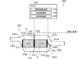
図2は、排気ガス浄化装置200の構成を示す概略図である。なお、図2中、信号の流れを破線の矢印で示し、エンジン120が搭載される車両の車体を一点鎖線で示す。図2に示すように、排気ガス浄化装置200は、堆積量推定部194と、供給制御部196と、三元触媒(Three-Way Catalyst)210と、フィルタユニット220と、酸素含有ガス供給部230とを含む。本実施形態において、排気ガス浄化装置200は、車体の下方に設けられる。
(Exhaust gas purification device 200)
FIG. 2 is a schematic diagram showing the configuration of the exhaust gas purification device 200. In FIG. 2, the signal flow is indicated by a dashed arrow, and the vehicle body of the vehicle on which the engine 120 is mounted is indicated by an alternate long and short dash line. As shown in FIG. 2, the exhaust gas purification apparatus 200 includes a deposition amount estimation unit 194, a supply control unit 196, a three-way catalyst (Three-Way Catalyst) 210, a filter unit 220, and an oxygen-containing gas supply unit 230. Including. In the present embodiment, the exhaust gas purification device 200 is provided below the vehicle body.

三元触媒210は、上流排気管140a内に設けられる。三元触媒210は、例えば、プラチナ(Pt)、パラジウム(Pd)、ロジウム(Rh)等の触媒成分を含む。三元触媒210は、排気ポート136から排出された排気ガス中の炭化水素、一酸化炭素、窒素酸化物を除去する。   The three-way catalyst 210 is provided in the upstream exhaust pipe 140a. The three-way catalyst 210 includes a catalyst component such as platinum (Pt), palladium (Pd), rhodium (Rh), for example. The three-way catalyst 210 removes hydrocarbons, carbon monoxide, and nitrogen oxides in the exhaust gas discharged from the exhaust port 136.

フィルタユニット220は、管体222と、GPF(フィルタ)224とを含む。管体222は、上流排気管140aと下流排気管140bとを接続する。上流排気管140aおよび管体222は、これらの連通箇所222aが管体222の流路断面の中央より車体側に位置するように接続される。また、管体222および下流排気管140bは、これらの連通箇所222bが管体222の流路断面の中央より車体から離隔した位置となるように接続される。   The filter unit 220 includes a tubular body 222 and a GPF (filter) 224. The pipe body 222 connects the upstream exhaust pipe 140a and the downstream exhaust pipe 140b. The upstream exhaust pipe 140a and the pipe body 222 are connected such that these communication portions 222a are located on the vehicle body side from the center of the cross section of the flow path of the pipe body 222. In addition, the pipe body 222 and the downstream exhaust pipe 140b are connected so that the communication portion 222b is located away from the vehicle body from the center of the cross section of the flow path of the pipe body 222.

GPF224は、管体222内に設けられる。つまり、GPF224は、排気管140内における三元触媒210の下流側に設けられる。GPF224は、排気ポート136から排気された排気ガス中の粒子状物質(煤)を捕捉する。   The GPF 224 is provided in the tube body 222. That is, the GPF 224 is provided on the downstream side of the three-way catalyst 210 in the exhaust pipe 140. The GPF 224 captures particulate matter (soot) in the exhaust gas exhausted from the exhaust port 136.

図3は、GPF224を説明する図である。図3(a)は、GPF224の斜視図である。図3(b)はGPF224の正面図である。図3(c)は、GPF224のYZ断面図である。なお、図3(a)中、排気ガスの流れを白抜き矢印で示し、図3(c)中、排気ガスの流れを実線の矢印で示す。また、本実施形態の図3では、垂直に交わるX軸、Y軸(排気ガスの流れ方向)、Z軸を図示の通り定義している。さらに、図3(a)〜図3(c)において、理解を容易にするために、外筒312に対してセル316を大きく示す。   FIG. 3 is a diagram for explaining the GPF 224. FIG. 3A is a perspective view of the GPF 224. FIG. 3B is a front view of the GPF 224. FIG. 3C is a YZ sectional view of the GPF 224. In FIG. 3A, the flow of exhaust gas is indicated by white arrows, and in FIG. 3C, the flow of exhaust gas is indicated by solid arrows. Further, in FIG. 3 of the present embodiment, the X axis, the Y axis (exhaust gas flow direction), and the Z axis that intersect perpendicularly are defined as illustrated. Further, in FIG. 3A to FIG. 3C, the cell 316 is shown larger than the outer cylinder 312 for easy understanding.

図3(a)〜図3(c)に示すように、GPF224は、ウォールフロー型のフィルタである。GPF224は、フィルタ部310と、上流プラグ部320と、下流プラグ部330とを含む。   As shown in FIGS. 3A to 3C, the GPF 224 is a wall flow type filter. The GPF 224 includes a filter unit 310, an upstream plug unit 320, and a downstream plug unit 330.

フィルタ部310は、円筒形状の外筒312と、排気ガスを通過させるフィルタ壁314とを含む。外筒312は、例えば、セラミックで構成される。   The filter unit 310 includes a cylindrical outer cylinder 312 and a filter wall 314 through which exhaust gas passes. The outer cylinder 312 is made of ceramic, for example.

フィルタ壁314は、例えば、セラミックで構成される。フィルタ壁314には、排気ガスに含まれる粒子状物質を捕捉しつつ排気ガスを通過させる孔が複数形成されている。フィルタ壁314は、図3中、XY面と平行な面上に設けられるとともに、Y軸方向に延在する第1壁314aと、YZ面と平行な面上に設けられるとともに、Y軸方向に延在する第2壁314bとを含む。そして、図3(b)に示すように、2つの第1壁314aと、2つの第2壁314bに囲繞された空間、もしくは、第1壁314a、第2壁314b、外筒312に囲繞された空間がセル316として形成される。   The filter wall 314 is made of ceramic, for example. The filter wall 314 has a plurality of holes through which exhaust gas passes while capturing particulate matter contained in the exhaust gas. In FIG. 3, the filter wall 314 is provided on a plane parallel to the XY plane, the first wall 314a extending in the Y axis direction, and provided on a plane parallel to the YZ plane, and in the Y axis direction. And an extending second wall 314b. Then, as shown in FIG. 3B, the space surrounded by the two first walls 314a and the two second walls 314b, or the first wall 314a, the second wall 314b, and the outer cylinder 312 is surrounded. A space is formed as a cell 316.

したがって、複数のセル316は、外筒312(フィルタ部310)内において、外筒312の軸方向(図3中、Y軸方向)に延在するとともに、軸方向と直交する方向(図3中、X軸方向およびZ軸方向)に並列して配される。また、GPF224では、第1セル群に分類されるセル316Aと、第2セル群に分類されるセル316Bとが交互に配置される。つまり、セル316Aとセル316Bとは隣接して交互に配される。   Therefore, the plurality of cells 316 extend in the axial direction (Y-axis direction in FIG. 3) of the outer cylinder 312 in the outer cylinder 312 (filter unit 310) and in a direction orthogonal to the axial direction (in FIG. 3). , X axis direction and Z axis direction). In GPF 224, cells 316A classified into the first cell group and cells 316B classified into the second cell group are alternately arranged. That is, the cells 316A and the cells 316B are alternately arranged adjacent to each other.

上流プラグ部320は、図3(c)に示すように、セル316のうち、第1セル群に分類されるセル316Aの上流側の上流開口318aを封止する。上流プラグ部320は、例えば、セラミックで構成される。   As shown in FIG. 3C, the upstream plug portion 320 seals the upstream opening 318a on the upstream side of the cell 316A that is classified into the first cell group among the cells 316. The upstream plug portion 320 is made of, for example, ceramic.

下流プラグ部330は、図3(c)に示すように、セル316A以外の(第2セル群に分類される)セル316Bの下流側の下流開口318bを封止する。下流プラグ部330は、例えば、セラミックで構成される。   As shown in FIG. 3C, the downstream plug portion 330 seals the downstream opening 318b on the downstream side of the cell 316B (classified as the second cell group) other than the cell 316A. The downstream plug portion 330 is made of ceramic, for example.

また、本実施形態においてGPF224は、粒子状物質を捕捉する機能を有するとともに、排気ガスを浄化する三元触媒としての機能とOSC(Oxygen Storage capacity)としての機能とを有する。具体的に説明すると、GPF224を構成するフィルタ壁314には三元触媒を構成する触媒成分およびOSC材が担持されている。   In the present embodiment, the GPF 224 has a function of capturing particulate matter, a function as a three-way catalyst for purifying exhaust gas, and a function as OSC (Oxygen Storage capacity). More specifically, the filter wall 314 constituting the GPF 224 carries the catalyst component constituting the three-way catalyst and the OSC material.

このように、排気ガス浄化装置200は、排気管140にGPF224を備える構成により、GPF224に粒子状物質を堆積させて、排気ガスから除去することができる。そして、GPF224に堆積した粒子状物質(炭素C)は、下記式(1)に示す反応(粒子状物質の酸化反応)を進行させることによってGPF224から除去され、GPF224が再生される。
C + O → CO …式(1)
As described above, the exhaust gas purifying apparatus 200 can remove the particulate matter from the exhaust gas by depositing the particulate matter on the GPF 224 by the configuration including the GPF 224 in the exhaust pipe 140. Then, the particulate matter (carbon C) deposited on the GPF 224 is removed from the GPF 224 by a reaction (oxidation reaction of the particulate matter) represented by the following formula (1), and the GPF 224 is regenerated.
C + O 2 → CO 2 Formula (1)

しかし、本実施形態のエンジン120はガソリンエンジンであるため、噴射量決定部186は、基本的に理論空燃比(ストイキ)となるように燃料の目標噴射量を決定する。理論空燃比での運転では、排気ガスに含まれる酸素が低濃度となるため、GPF224の再生処理が促進されない。   However, since the engine 120 of the present embodiment is a gasoline engine, the injection amount determination unit 186 basically determines the target injection amount of fuel so that the stoichiometric air-fuel ratio (stoichiometric) is obtained. In the operation at the stoichiometric air-fuel ratio, the oxygen contained in the exhaust gas has a low concentration, so that the regeneration process of the GPF 224 is not promoted.

そこで、排気ガス浄化装置200は、酸素含有ガス供給部230を含み、GPF224における粒子状物質の堆積量が所定の堆積閾値以上になった場合に、酸素含有ガス供給部230を駆動してGPF224に供給される酸素濃度を増加させる。   Therefore, the exhaust gas purification apparatus 200 includes an oxygen-containing gas supply unit 230. When the amount of particulate matter deposited in the GPF 224 exceeds a predetermined deposition threshold, the oxygen-containing gas supply unit 230 is driven to the GPF 224. Increase the oxygen concentration supplied.

図2に戻って具体的に説明すると、酸素含有ガス供給部230は、供給管232と、ポンプ234とを含む。供給管232は、上流排気管140aにおける三元触媒210と管体222(GPF224)との間に接続され、端部が大気開放される。ポンプ234は、供給管232に設けられ、外気(酸素含有ガス)を供給管232に供給する。   Returning specifically to FIG. 2, the oxygen-containing gas supply unit 230 includes a supply pipe 232 and a pump 234. The supply pipe 232 is connected between the three-way catalyst 210 and the pipe body 222 (GPF 224) in the upstream exhaust pipe 140a, and the end thereof is opened to the atmosphere. The pump 234 is provided in the supply pipe 232 and supplies outside air (oxygen-containing gas) to the supply pipe 232.

堆積量推定部194は、GPF224における粒子状物質の堆積量を推定する。堆積量推定部194は、例えば、エンジン120の運転条件や、前回外気を供給してから現在までの運転時間(走行距離)に基づいて粒子状物質の堆積量を推定する。   The accumulation amount estimation unit 194 estimates the accumulation amount of particulate matter in the GPF 224. The accumulation amount estimation unit 194 estimates the accumulation amount of the particulate matter based on, for example, the operating conditions of the engine 120 and the operation time (travel distance) from the previous supply of outside air to the present.

供給制御部196は、堆積量が堆積閾値以上であるとき、排気ガスの温度等のエンジン運転状態が再生処理条件を満たすと、酸素含有ガス供給部230を制御して、外気の供給を開始させる。   The supply control unit 196 controls the oxygen-containing gas supply unit 230 to start the supply of outside air when the engine operation state such as the exhaust gas temperature satisfies the regeneration processing condition when the accumulation amount is equal to or greater than the accumulation threshold. .

このように、外気を供給して再生処理を実行することで、GPF224に堆積した粒子状物質(煤)を効率よく燃焼させる。本実施形態の排気ガス浄化装置200は、上流排気管140aに対するGPF224の配置を工夫することで、再生処理において粒子状物質をさらに効率よく燃焼させる。   In this way, by supplying the outside air and executing the regeneration process, the particulate matter (soot) deposited on the GPF 224 is efficiently burned. The exhaust gas purification apparatus 200 of this embodiment devisees the arrangement of the GPF 224 with respect to the upstream exhaust pipe 140a, and thereby burns particulate matter more efficiently in the regeneration process.

図2に示すように、GPF224は、管体222内を上流空間Uと下流空間Dとに仕切る。ここで、上流空間Uは、管体222内における上流排気管140aと連通する空間である。下流空間Dは、管体222内における下流排気管140bと連通する空間である。また、GPF224は、上流空間Uにセルの上流開口318aが臨み、下流空間Dにセルの下流開口318bが臨むように、管体222内に設けられる。   As shown in FIG. 2, the GPF 224 partitions the inside of the tubular body 222 into an upstream space U and a downstream space D. Here, the upstream space U is a space communicating with the upstream exhaust pipe 140 a in the tube body 222. The downstream space D is a space communicating with the downstream exhaust pipe 140b in the tube body 222. The GPF 224 is provided in the pipe body 222 so that the upstream opening 318a of the cell faces the upstream space U and the downstream opening 318b of the cell faces the downstream space D.

さらに、本実施形態において、GPF224は、外筒312の軸方向の長さが外筒312の内径よりも小さく形成されるとともに、上流排気管140aおよび下流排気管140bの軸方向と、外筒312の軸方向とが交差するように管体222内に設けられる。例えば、GPF224は、外筒312の軸方向が鉛直方向となるように、または、外筒312の軸方向が鉛直方向から上流側に0度を上回り45度未満傾斜するように、管体222内に設けられる。   Further, in the present embodiment, the GPF 224 is formed such that the axial length of the outer cylinder 312 is smaller than the inner diameter of the outer cylinder 312, the axial direction of the upstream exhaust pipe 140 a and the downstream exhaust pipe 140 b, and the outer cylinder 312. The tube body 222 is provided so as to intersect with the axial direction. For example, the GPF 224 is arranged in the tubular body 222 so that the axial direction of the outer cylinder 312 is the vertical direction, or the axial direction of the outer cylinder 312 is inclined more than 0 degrees and less than 45 degrees upstream from the vertical direction. Is provided.

したがって、軸方向が水平方向(上流排気管140a、下流排気管140bの軸方向と平行)となるようにGPF224が設けられる従来技術と比較して、管体222の鉛直方向の幅を小さくしたまま、GPF224の流路断面積(外筒312の内径)を大きくすることができる。これにより、車体の下方といったスーペースが制限された場所に、流路断面積が相対的に大きいGPF224を配置することが可能となる。また、GPF224の流路断面積を相対的に大きくすることにより、流路断面積が小さいGPF224よりも圧力損失を低くすることができる。これにより、燃費を向上することが可能となる。   Therefore, the vertical width of the tubular body 222 is kept small as compared with the conventional technique in which the GPF 224 is provided so that the axial direction is the horizontal direction (parallel to the axial direction of the upstream exhaust pipe 140a and the downstream exhaust pipe 140b). , The cross-sectional area of the GPF 224 (the inner diameter of the outer cylinder 312) can be increased. Accordingly, the GPF 224 having a relatively large flow path cross-sectional area can be disposed at a place where the space is limited, such as below the vehicle body. Further, by making the flow path cross-sectional area of the GPF 224 relatively large, the pressure loss can be made lower than that of the GPF 224 having a small flow path cross-sectional area. Thereby, fuel consumption can be improved.

なお、GPF224は、不図示のストッパに支持される。ストッパは、GPF224の下方に設けられ、管体222から延在している。また、GPF224の下部と管体222(ストッパ)との間隙には、耐熱性を有するセラミックウールが充填されている。   The GPF 224 is supported by a stopper (not shown). The stopper is provided below the GPF 224 and extends from the tube body 222. Further, the gap between the lower part of the GPF 224 and the tube body 222 (stopper) is filled with ceramic wool having heat resistance.

また、本実施形態のGPF224は、外筒312における最も上流側かつ鉛直上方の部位Mが、管体222と非接触となり、かつ、連通箇所222aに臨むように管体222内に設けられる。   Further, the GPF 224 of the present embodiment is provided in the tubular body 222 such that the most upstream and vertically upper portion M of the outer cylinder 312 is not in contact with the tubular body 222 and faces the communicating portion 222a.

そうすると、上流排気管140aを流れる高温の排気ガスは、最初に部位Mに接触することになる。したがって、部位Mは、通常運転時(再生処理を実行していないとき)に排気ガスの熱を効率よく蓄積することができる。また、部位Mは、管体222と非接触であるため、蓄積した熱が管体222を通じて外部に放熱されることを回避可能となる。   Then, the high-temperature exhaust gas flowing through the upstream exhaust pipe 140a first comes into contact with the part M. Therefore, the part M can efficiently accumulate the heat of the exhaust gas during normal operation (when the regeneration process is not executed). Further, since the portion M is not in contact with the tube body 222, it is possible to avoid the accumulated heat from being radiated to the outside through the tube body 222.

このように、通常運転時に部位Mで熱を蓄積しておくことにより、再生処理を開始する前において、部位Mが最も高温となる。そして、再生処理を実行すべく、ポンプ234が駆動されて外気が供給されると、外気は、上流排気管140a、連通箇所222aを通じてGPF224に到達する。ここで、上記したように部位Mは、連通箇所222aに臨んでいるため、外気は、GPF224における部位Mに最初に到達する。そうすると、GPF224に蓄積した粒子状物質は、まず、部位Mの近傍から燃焼し始め、その後、下流側に延焼する。ここで、部位Mは、GPF224において最も高温となっているため、部位Mの近傍の粒子状物質の着火性を向上させることができる。したがって、GPF224の外筒312を管体222に接触させている従来技術と比較して、再生処理において、粒子状物質の燃焼性をさらに向上させることが可能となる。   In this way, by accumulating heat at the part M during normal operation, the part M reaches the highest temperature before the regeneration process is started. When the pump 234 is driven and external air is supplied to execute the regeneration process, the external air reaches the GPF 224 through the upstream exhaust pipe 140a and the communication portion 222a. Here, as described above, since the part M faces the communication part 222a, the outside air first reaches the part M in the GPF 224. Then, the particulate matter accumulated in the GPF 224 starts to burn from the vicinity of the part M, and then spreads to the downstream side. Here, since the part M has the highest temperature in the GPF 224, the ignitability of the particulate matter in the vicinity of the part M can be improved. Therefore, the combustibility of the particulate matter can be further improved in the regeneration process as compared with the conventional technique in which the outer cylinder 312 of the GPF 224 is in contact with the pipe body 222.

また、上記したように、連通箇所222aが車体側に設けられ、連通箇所222bが車体から離隔する方向に設けられ、セル316が連通箇所222aと連通箇所222bと(上流空間Uと下流空間Dと)を連通する。したがって、外気は、車体側から車体と離隔する方向に流れる。そうすると、GPF224に堆積された粒子状物質は、部位Mの近傍から燃焼しはじめ、その後、下流側、かつ、車体から離隔する方向に延焼する。   Further, as described above, the communication part 222a is provided on the vehicle body side, the communication part 222b is provided in a direction away from the vehicle body, and the cells 316 are connected to the communication part 222a and the communication part 222b (the upstream space U and the downstream space D). ). Therefore, outside air flows in a direction away from the vehicle body from the vehicle body side. Then, the particulate matter deposited on the GPF 224 starts to burn from the vicinity of the part M, and then spreads in the downstream side and in the direction away from the vehicle body.

したがって、排気ガス浄化装置200において、燃焼熱は、GPF224における車体から離隔する方向に伝搬する。このため、再生処理が実行された際、排気ガス浄化装置200において、GPF224の外筒312における最も下流側かつ鉛直下方の部位Nは、上流側かつ車体側から伝搬した熱と、粒子状物質の燃焼熱とが合わさり、最も高温となる。   Therefore, in the exhaust gas purification apparatus 200, the combustion heat propagates in a direction away from the vehicle body in the GPF 224. For this reason, when the regeneration process is executed, in the exhaust gas purifying apparatus 200, the most downstream and vertically lower portion N of the outer cylinder 312 of the GPF 224 has the heat propagated from the upstream side and the vehicle body side, and the particulate matter Combined with combustion heat, it becomes the highest temperature.

このように、再生処理を実行した際に最も高温となる部位を車体から離隔した位置とすることができる。これにより、再生処理において生じた熱の車体への伝搬を抑制することが可能となる。したがって、熱による車体への影響を抑制することができる。   In this way, the portion that becomes the highest temperature when the regeneration process is executed can be set at a position separated from the vehicle body. Thereby, propagation of heat generated in the regeneration process to the vehicle body can be suppressed. Therefore, the influence on the vehicle body due to heat can be suppressed.

(第1の変形例)
上記実施形態において、管体222内に1のGPF224が設けられる構成を例に挙げて説明した。しかし、GPF224の数に限定はない。
(First modification)
In the above embodiment, the configuration in which one GPF 224 is provided in the tubular body 222 has been described as an example. However, the number of GPFs 224 is not limited.

図4は、第1の変形例のフィルタユニット420の構成を示す概略図である。なお、図4中、車体を一点鎖線で示す。また、上記排気ガス浄化装置200のフィルタユニット220と実質的に等しい構成要素については、同一の符号を付して説明を省略する。   FIG. 4 is a schematic diagram showing the configuration of the filter unit 420 of the first modification. In addition, in FIG. 4, a vehicle body is shown with a dashed-dotted line. In addition, components that are substantially the same as the filter unit 220 of the exhaust gas purification device 200 are given the same reference numerals, and descriptions thereof are omitted.

フィルタユニット420は、管体222内に、2つのGPF224(図4中、224A、224Bで示す)が設けられている点のみがフィルタユニット220と異なる。   The filter unit 420 is different from the filter unit 220 only in that two GPFs 224 (indicated by 224A and 224B in FIG. 4) are provided in the tube body 222.

具体的に説明すると、管体222内において上流側に位置するGPF224Aおよび下流側に位置するGPF224Bは、外筒312同士が接触し、かつ、外筒312の軸方向が平行となるように管体222内に設けられる。   More specifically, the GPF 224A located on the upstream side and the GPF 224B located on the downstream side in the tubular body 222 are arranged so that the outer cylinders 312 are in contact with each other and the axial directions of the outer cylinders 312 are parallel to each other. 222 is provided.

また、GPF224A、224Bは、上流排気管140aおよび下流排気管140bの軸方向と、外筒312の軸方向とが交差するように管体222内に設けられる。例えば、GPF224A、224Bは、外筒312の軸方向が鉛直方向となるように、または、外筒312の軸方向が鉛直方向から上流側に0度を上回り45度未満傾斜するように、管体222内に設けられる。   Further, the GPFs 224A and 224B are provided in the pipe body 222 so that the axial directions of the upstream exhaust pipe 140a and the downstream exhaust pipe 140b intersect the axial direction of the outer cylinder 312. For example, the GPFs 224A and 224B have a tubular body so that the axial direction of the outer cylinder 312 is a vertical direction, or the axial direction of the outer cylinder 312 is inclined more than 0 degree and more than 45 degrees upstream from the vertical direction. 222 is provided.

また、GPF224Aは、外筒312における最も上流側かつ鉛直上方の部位Mが、管体222と非接触となり、かつ、連通箇所222aに臨むように管体222内に設けられる。これにより、上記フィルタユニット220と同様に、通常運転時において部位Mは、排気ガスの熱を効率よく蓄積することができる。また、部位Mは、管体222と非接触であるため、蓄積した熱が管体222を通じて外部に放熱されることを回避可能となる。   Further, the GPF 224A is provided in the tubular body 222 so that the most upstream and vertically upper portion M of the outer cylinder 312 is not in contact with the tubular body 222 and faces the communication portion 222a. Thereby, like the filter unit 220, the part M can efficiently accumulate the heat of the exhaust gas during the normal operation. Further, since the portion M is not in contact with the tube body 222, it is possible to avoid the accumulated heat from being radiated to the outside through the tube body 222.

また、GPF224A、224Bは、管体222内を上流空間Uと下流空間Dとに仕切る。GPF224A、224Bは、上流空間Uにセルの上流開口318aが臨み、下流空間Dにセルの下流開口318bが臨むように、管体222内に設けられる。   The GPFs 224A and 224B partition the inside of the tubular body 222 into an upstream space U and a downstream space D. The GPFs 224A and 224B are provided in the pipe body 222 so that the upstream opening 318a of the cell faces the upstream space U and the downstream opening 318b of the cell faces the downstream space D.

そして、上記したように、連通箇所222aが車体側に設けられ、連通箇所222bが車体から離隔する方向に設けられ、GPF224A、224Bのセル316が連通箇所222aと連通箇所222bと(上流空間Uと下流空間Dと)を連通する。したがって、外気は、車体側から車体と離隔する方向に流れる。そうすると、GPF224に堆積された粒子状物質は、部位Mの近傍から燃焼しはじめ、その後、下流側、かつ、車体から離隔する方向に延焼する。   As described above, the communication location 222a is provided on the vehicle body side, the communication location 222b is provided in a direction away from the vehicle body, and the cells 316 of the GPFs 224A and 224B are connected to the communication location 222a and the communication location 222b (the upstream space U and Communicate with downstream space D). Therefore, outside air flows in a direction away from the vehicle body from the vehicle body side. Then, the particulate matter deposited on the GPF 224 starts to burn from the vicinity of the part M, and then spreads in the downstream side and in the direction away from the vehicle body.

したがって、フィルタユニット420においても、フィルタユニット220と同様に、燃焼熱は、GPF224A、224Bにおける車体から離隔する方向に伝搬する。このため、再生処理が実行された際、GPF224A、224Bの外筒312における最も下流側かつ鉛直下方の部位Nは、上流側かつ車体側から伝搬した熱と、粒子状物質の燃焼熱とが合わさり、最も高温となる。   Therefore, also in the filter unit 420, the combustion heat propagates in a direction away from the vehicle body in the GPFs 224A and 224B, as in the filter unit 220. For this reason, when the regeneration process is executed, the most downstream and vertically downward portion N of the outer cylinder 312 of the GPFs 224A and 224B is combined with the heat propagated from the upstream side and the vehicle body side and the combustion heat of the particulate matter. The highest temperature.

このように、再生処理を実行した際に最も高温となる部位を車体から離隔した位置とすることができる。これにより、再生処理において生じた熱の車体への伝搬を抑制することが可能となる。したがって、熱による車体への影響を抑制することができる。また、第1の変形例のフィルタユニット420は、フィルタユニット220と異なり、既存のGPF224を採用することができる。   In this way, the portion that becomes the highest temperature when the regeneration process is executed can be set at a position separated from the vehicle body. Thereby, propagation of heat generated in the regeneration process to the vehicle body can be suppressed. Therefore, the influence on the vehicle body due to heat can be suppressed. Further, unlike the filter unit 220, the existing GPF 224 can be adopted for the filter unit 420 of the first modified example.

(第2の変形例)
図5は、第2の変形例の排気ガス浄化装置500の構成を示す概略図である。なお、図5中、信号の流れを破線の矢印で示し、車体を一点鎖線で示す。また、図5中、理解を容易にするために、三元触媒210、酸素含有ガス供給部230を省略する。また、上記排気ガス浄化装置200のフィルタユニット220、フィルタユニット420と実質的に等しい構成要素については、同一の符号を付して説明を省略する。
(Second modification)
FIG. 5 is a schematic diagram showing a configuration of an exhaust gas purifying apparatus 500 of a second modification. In FIG. 5, the signal flow is indicated by broken arrows, and the vehicle body is indicated by a one-dot chain line. Further, in FIG. 5, the three-way catalyst 210 and the oxygen-containing gas supply unit 230 are omitted for easy understanding. In addition, components that are substantially the same as the filter unit 220 and the filter unit 420 of the exhaust gas purification device 200 are given the same reference numerals, and descriptions thereof are omitted.

排気ガス浄化装置500は、堆積量推定部194と、供給制御部196と、切替制御部590と、三元触媒210と、フィルタユニット520と、第1バルブ(切替機構)530と、第2バルブ(切替機構)540と、酸素含有ガス供給部230とを含む。排気ガス浄化装置500は、車体の下方に設けられる。   The exhaust gas purification apparatus 500 includes a deposition amount estimation unit 194, a supply control unit 196, a switching control unit 590, a three-way catalyst 210, a filter unit 520, a first valve (switching mechanism) 530, and a second valve. (Switching mechanism) 540 and oxygen-containing gas supply unit 230 are included. The exhaust gas purification device 500 is provided below the vehicle body.

フィルタユニット520は、フィルタユニット420と同様に、管体222内に、2つのGPF224(図5中、224A、224Bで示す)が設けられている。なお、下流側に位置するGPF224Bは、フィルタユニット420とは異なり、外筒312が管体222から離隔して管体222内に設けられる。また、GPF224A、224Bは、外筒312の軸方向が鉛直方向となるように、管体222内に設けられる。   Similarly to the filter unit 420, the filter unit 520 is provided with two GPFs 224 (indicated by 224A and 224B in FIG. 5) in the tube body 222. In the GPF 224 </ b> B located on the downstream side, unlike the filter unit 420, the outer cylinder 312 is separated from the tube body 222 and provided in the tube body 222. The GPFs 224A and 224B are provided in the tubular body 222 so that the axial direction of the outer cylinder 312 is the vertical direction.

第1バルブ530は、上流空間Uに設けられる。第1バルブ530は、回転軸532と、弁体534とを有する。回転軸532は、管体222における上流空間Uを区画する部分、詳細には管体222の上面に設けられる。弁体534は、回転軸532に接続され、回転軸532によって回転自在となっている。弁体534は、先端が、GPF224Aの外筒312と、GPF224Bの外筒312との接触箇所(詳細には接触箇所の上端)に当接可能となっている。   The first valve 530 is provided in the upstream space U. The first valve 530 has a rotating shaft 532 and a valve body 534. The rotating shaft 532 is provided on a portion of the tubular body 222 that divides the upstream space U, specifically on the upper surface of the tubular body 222. The valve body 534 is connected to the rotation shaft 532 and is rotatable by the rotation shaft 532. The tip of the valve body 534 can come into contact with a contact portion (specifically, an upper end of the contact portion) between the outer cylinder 312 of the GPF 224A and the outer cylinder 312 of the GPF 224B.

第1バルブ530は、後述する切替制御部590によって、弁体534が外筒312の接触箇所に当接している第1状態と、弁体534が外筒312の接触箇所から離隔している第2状態とに切り替わる。   The first valve 530 has a first state in which the valve body 534 is in contact with a contact location of the outer cylinder 312 and a first state where the valve body 534 is separated from the contact location of the outer cylinder 312 by a switching control unit 590 described later. Switch to 2 state.

第2バルブ540は、上流空間Uと下流空間Dの連通空間に設けられる。第2バルブ540は、回転軸542と、弁体544とを有する。回転軸542は、GPF224Bの外筒312における下流側に設けられる。弁体544は、回転軸542に接続され、回転軸542によって回転自在となっている。弁体544は、先端が、管体222における上流空間Uを区画する部分222u、および、管体222における下流空間Dを区画する部分222dに当接可能となっている。   The second valve 540 is provided in a communication space between the upstream space U and the downstream space D. The second valve 540 has a rotating shaft 542 and a valve body 544. The rotating shaft 542 is provided on the downstream side of the outer cylinder 312 of the GPF 224B. The valve body 544 is connected to the rotation shaft 542 and is rotatable by the rotation shaft 542. The valve body 544 has a distal end capable of coming into contact with a portion 222 u that partitions the upstream space U in the tube body 222 and a portion 222 d that partitions the downstream space D in the tube body 222.

第2バルブ540は、切替制御部590によって、弁体544が部分222uに当接している第3状態と、弁体544が部分222dに当接している第4状態とに切り替わる。   The switching control unit 590 switches the second valve 540 between a third state in which the valve body 544 is in contact with the portion 222u and a fourth state in which the valve body 544 is in contact with the portion 222d.

切替制御部590は、第1バルブ530を第1状態とし、第2バルブ540を第4状態とする直列状態と、第1バルブ530を第2状態とし、第2バルブ540を第3状態とする並列状態とに切り替える。   The switching control unit 590 sets the first valve 530 in the first state, the second valve 540 in the fourth state, the first valve 530 in the second state, and the second valve 540 in the third state. Switch to parallel state.

図6は、直列状態と、並列状態とを説明する図である。図6(a)は、直列状態について説明する図である。図6(b)は、並列状態について説明する図である。なお、図6(a)、(b)中、排気ガス(または外気)の流れを実線の矢印で示す。   FIG. 6 is a diagram illustrating a series state and a parallel state. FIG. 6A is a diagram illustrating the serial state. FIG. 6B illustrates the parallel state. In FIGS. 6A and 6B, the flow of exhaust gas (or outside air) is indicated by solid arrows.

図6(a)に示すように、切替制御部590が、第1バルブ530を第1状態とし、第2バルブ540を第4状態としたとする。そうすると、上流排気管140aから管体222に導入された排気ガスは、まず、GPF224A(第1のフィルタ)を上方から下方に向かって(車体と離隔する方向に)通過し、下流空間Dに到達する。その後、下流空間Dに到達した排気ガスは、GPF224B(第2のフィルタ)を下方から上方に向かって(車体に近接する方向に)通過する。そして、GPF224Bを通過した排気ガスは、連通箇所222bを通じて、下流排気管140bに導かれる。つまり、直列状態は、GPF224AとGPF224Bを直列に配置し、上流排気管140aから管体222に導入された排気ガスを、GPF224Aに通過させた後、GPF224Bに通過させて下流排気管140bに導く状態と言える。   As shown in FIG. 6A, the switching control unit 590 assumes that the first valve 530 is in the first state and the second valve 540 is in the fourth state. Then, the exhaust gas introduced into the pipe body 222 from the upstream exhaust pipe 140a first passes through the GPF 224A (first filter) from the upper side to the lower side (in a direction away from the vehicle body) and reaches the downstream space D. To do. Thereafter, the exhaust gas that has reached the downstream space D passes through the GPF 224B (second filter) from below to above (in a direction close to the vehicle body). And the exhaust gas which passed GPF224B is guide | induced to the downstream exhaust pipe 140b through the communication location 222b. That is, in the serial state, GPF 224A and GPF 224B are arranged in series, and the exhaust gas introduced into the pipe body 222 from the upstream exhaust pipe 140a is passed through the GPF 224A and then passed through the GPF 224B to be led to the downstream exhaust pipe 140b. It can be said.

また、図6(b)に示すように、切替制御部590が、第1バルブ530を第2状態とし、第2バルブ540を第3状態としたとする。そうすると、上流排気管140aから管体222に導入された排気ガスは、GPF224AおよびGPF224Bのいずれかを上方から下方に向かって(車体と離隔する方向に)通過し、下流空間Dに到達する。その後、下流空間Dに到達した排気ガスは、連通箇所222bを通じて、下流排気管140bに導かれる。つまり、並列状態は、GPF224AとGPF224Bを並列に配置し、上流排気管140aから管体222に導入された排気ガスを、GPF224AまたはGPF224Bに通過させて下流排気管140bに導く状態と言える。   Further, as illustrated in FIG. 6B, the switching control unit 590 assumes that the first valve 530 is in the second state and the second valve 540 is in the third state. Then, the exhaust gas introduced into the pipe body 222 from the upstream exhaust pipe 140a passes through one of the GPF 224A and GPF 224B from the upper side to the lower side (in a direction away from the vehicle body) and reaches the downstream space D. Thereafter, the exhaust gas reaching the downstream space D is guided to the downstream exhaust pipe 140b through the communication portion 222b. That is, it can be said that the parallel state is a state in which the GPF 224A and the GPF 224B are arranged in parallel and the exhaust gas introduced from the upstream exhaust pipe 140a into the pipe body 222 is passed through the GPF 224A or GPF 224B and guided to the downstream exhaust pipe 140b.

このように、切替制御部590は、第1バルブ530および第2バルブ540を制御して、排気ガスの通過経路を直列状態と並列状態とに切替える。例えば、切替制御部590は、エンジン120の始動時や再生処理を実行する際に、直列状態に切替える。エンジン120の始動時は、排気ガス中の粒子状物質の濃度が相対的に高いため、排気ガスの通過経路を直列状態とすることにより、GPF224A、224Bに効率よく粒子状物質を捕捉させることができる。また、再生処理を実行する際に、直列状態とすることにより、GPF224Aの外筒312における最も上流側かつ鉛直上方の部位Mを着火点として効率よく燃焼を開始させることができる。また、GPF224Bには、GPF224Aによって加熱された外気が供給されるため、GPF224Bにおいて効率よく燃焼を開始させることが可能となる。さらに、GPF224Aにおいて浄化しきれなかった成分をGPF224Bで浄化させることもできる。   In this manner, the switching control unit 590 controls the first valve 530 and the second valve 540 to switch the exhaust gas passage path between the series state and the parallel state. For example, the switching control unit 590 switches to the serial state when the engine 120 is started or when regeneration processing is executed. Since the concentration of particulate matter in the exhaust gas is relatively high when the engine 120 is started, the particulate matter can be efficiently captured by the GPFs 224A and 224B by setting the exhaust gas passage route in series. it can. In addition, when the regeneration process is executed, the combustion state can be efficiently started by setting the most upstream and vertical upper portion M of the outer cylinder 312 of the GPF 224A as the ignition point by setting the state in series. Further, since the outside air heated by the GPF 224A is supplied to the GPF 224B, the GPF 224B can start combustion efficiently. Furthermore, components that could not be purified by GPF 224A can be purified by GPF 224B.

また、切替制御部590は、エンジン120の暖機が終了した場合や、エンジン120が高負荷となっている場合に、排気ガスの通過経路を並列状態に切替える。これにより、直列状態と比較して、GPF224A、224Bによる圧力損失を低減することができる。   Further, the switching control unit 590 switches the exhaust gas passage route to a parallel state when the engine 120 has been warmed up or when the engine 120 has a high load. Thereby, the pressure loss by GPF224A, 224B can be reduced compared with a serial state.

以上、添付図面を参照しながら本発明の好適な実施形態について説明したが、本発明はかかる実施形態に限定されないことは言うまでもない。当業者であれば、特許請求の範囲に記載された範疇において、各種の変更例または修正例に想到し得ることは明らかであり、それらについても当然に本発明の技術的範囲に属するものと了解される。   As mentioned above, although preferred embodiment of this invention was described referring an accompanying drawing, it cannot be overemphasized that this invention is not limited to this embodiment. It will be apparent to those skilled in the art that various changes and modifications can be made within the scope of the claims, and these are naturally within the technical scope of the present invention. Is done.

なお、上記実施形態および変形例において、ECU110が堆積量推定部194、供給制御部196、切替制御部590として機能する構成を例に挙げて説明した。しかし、堆積量推定部194、供給制御部196、切替制御部590は、ECU110と別体で構成されてもよい。   In the embodiment and the modification described above, the configuration in which the ECU 110 functions as the accumulation amount estimation unit 194, the supply control unit 196, and the switching control unit 590 has been described as an example. However, the accumulation amount estimation unit 194, the supply control unit 196, and the switching control unit 590 may be configured separately from the ECU 110.

また、上記実施形態および変形例において、GPF224としてウォールフロー型のフィルタを例に挙げて説明した。しかし、GPF224は、少なくとも外筒312と、フィルタ壁とを有していればよく、構成に限定はない。   Moreover, in the said embodiment and modification, the wall flow type filter was mentioned as an example and demonstrated as GPF224. However, the GPF 224 only needs to have at least the outer cylinder 312 and the filter wall, and the configuration is not limited.

また、上記実施形態におよび変形例において、GPF224が触媒を含む構成を例に挙げて説明したが、GPF224は粒子状物質を捕捉できればよく、触媒を含まずともよい。   In the above-described embodiment and the modification, the GPF 224 is described as an example of the configuration including the catalyst. However, the GPF 224 may be capable of capturing the particulate matter and may not include the catalyst.

また、上記実施形態および変形例において、上流排気管140aと管体222との連通箇所222aは、車体側に位置し、管体222と下流排気管140bとの連通箇所222bは、連通箇所222aよりも車体から離隔している場合を例に挙げて説明した。しかし、連通箇所222aは、連通箇所222bよりも車体から離隔していてもよい。また、連通箇所222aと連通箇所222bとは同じ位置、つまり、上流排気管140aと下流排気管140bとが同軸であってもよい。   In the above-described embodiment and modification, the communication portion 222a between the upstream exhaust pipe 140a and the tube body 222 is located on the vehicle body side, and the communication portion 222b between the tube body 222 and the downstream exhaust pipe 140b is from the communication portion 222a. As an example, the case of being separated from the vehicle body has been described. However, the communication location 222a may be further away from the vehicle body than the communication location 222b. Further, the communication location 222a and the communication location 222b may be at the same position, that is, the upstream exhaust pipe 140a and the downstream exhaust pipe 140b may be coaxial.

また、上記実施形態および変形例において、外筒312における最も上流側かつ鉛直上方の部位Mが、管体222と非接触となる構成を例に挙げて説明した。しかし、外筒312における上流空間Uに位置する部位であって、連通箇所222aから所定範囲内の部位が、管体222と非接触となっていればよい。例えば、外筒312の連通箇所222a側の側面であって、上流空間Uに位置する部位が管体222と非接触になっていてもよい。   In the above-described embodiment and the modification, the configuration in which the most upstream portion M in the outer cylinder 312 is vertically in contact with the tubular body 222 has been described as an example. However, the part located in the upstream space U in the outer cylinder 312 and a part within a predetermined range from the communication part 222 a may be in non-contact with the tubular body 222. For example, the part located in the upstream space U on the side of the communication portion 222 a of the outer cylinder 312 may be in non-contact with the tubular body 222.

また、上記第2の変形例の排気ガス浄化装置500において、切替機構が第1バルブ530および第2バルブ540を含む場合を例に挙げて説明した。しかし、切替機構は、上流排気管140aから管体222に導入された排気ガスを、第1のフィルタに通過させた後第2のフィルタに通過させて下流排気管140bに導く直列状態と、第1のフィルタに通過させるとともに第1のフィルタと並行して第2のフィルタに通過させて下流排気管140bに導く並列状態とに切り替えることができれば、構成に限定はない。   In the exhaust gas purifying apparatus 500 of the second modified example, the case where the switching mechanism includes the first valve 530 and the second valve 540 has been described as an example. However, the switching mechanism includes a serial state in which the exhaust gas introduced into the pipe body 222 from the upstream exhaust pipe 140a is passed through the first filter and then passed through the second filter to be led to the downstream exhaust pipe 140b. The configuration is not limited as long as it can be switched to the parallel state of passing through the first filter and passing through the second filter in parallel with the first filter and leading to the downstream exhaust pipe 140b.

また、上記実施形態および変形例において、酸素含有ガス供給部230が酸素含有ガスとして外気を供給する場合を例に挙げて説明した。しかし、酸素含有ガス供給部230が供給する酸素含有ガスは、理論空燃比の排気ガスより酸素濃度が高いガスであればよい。   Moreover, in the said embodiment and modification, the case where the oxygen containing gas supply part 230 supplies external air as an oxygen containing gas was mentioned as an example, and was demonstrated. However, the oxygen-containing gas supplied by the oxygen-containing gas supply unit 230 may be any gas having a higher oxygen concentration than the stoichiometric air-fuel ratio exhaust gas.

また、上記実施形態において、エンジン120としてガソリンエンジンを例に挙げて説明した。しかし、排気ガス浄化装置200、500は、エンジンの種類に限らず(例えば、ディーゼルエンジン)、エンジンから排気された排気ガスに含まれる粒子状物質を取り除くことができる。   Moreover, in the said embodiment, the gasoline engine was mentioned as an example and demonstrated as the engine 120. FIG. However, the exhaust gas purification devices 200 and 500 are not limited to the type of engine (for example, a diesel engine), and can remove particulate matter contained in the exhaust gas exhausted from the engine.

本発明は、排気ガス浄化装置に利用できる。   The present invention can be used for an exhaust gas purification device.

140a 上流排気管
140b 下流排気管
200、500 排気ガス浄化装置
222 管体
224 GPF(フィルタ)
312 外筒
314 フィルタ壁
316、316A、316B セル
318a 上流開口
318b 下流開口
530 第1バルブ(切替機構)
540 第2バルブ(切替機構)
590 切替制御部(切替機構)
140a Upstream exhaust pipe 140b Downstream exhaust pipe 200, 500 Exhaust gas purification device 222 Pipe body 224 GPF (filter)
312 outer cylinder 314 filter wall 316, 316A, 316B cell 318a upstream opening 318b downstream opening 530 first valve (switching mechanism)
540 Second valve (switching mechanism)
590 switching control unit (switching mechanism)

Claims (3)

エンジンから排気された排気ガスが通過する上流排気管と、
前記上流排気管の下流側に接続された管体と、
前記管体の下流側に接続された下流排気管と、
前記管体内に設けられ、前記管体内を、前記上流排気管と連通する上流空間と、前記下流排気管と連通する下流空間とに仕切る1または複数のフィルタと、
を備え、
前記フィルタは、
外筒と、前記外筒内に設けられたフィルタ壁とを有し、
前記上流排気管および前記下流排気管の軸方向と、前記外筒の軸方向とが交差するように、前記管体内に設けられ、
前記外筒における前記上流空間に位置する部位であって、前記上流排気管と前記管体との連通箇所から所定範囲内の部位は、前記管体と非接触になっている排気ガス浄化装置。
An upstream exhaust pipe through which exhaust gas exhausted from the engine passes,
A pipe connected to the downstream side of the upstream exhaust pipe;
A downstream exhaust pipe connected to the downstream side of the tubular body;
One or a plurality of filters provided in the pipe body and partitioning the pipe body into an upstream space communicating with the upstream exhaust pipe and a downstream space communicating with the downstream exhaust pipe;
With
The filter is
An outer cylinder, and a filter wall provided in the outer cylinder,
Provided in the tube so that the axial direction of the upstream exhaust pipe and the downstream exhaust pipe intersects the axial direction of the outer cylinder,
An exhaust gas purifying apparatus, wherein a part of the outer cylinder located in the upstream space and in a predetermined range from a communication part between the upstream exhaust pipe and the pipe body is not in contact with the pipe body.
前記フィルタは、前記エンジンが搭載される車両の車体の下方に配置され、
前記管体と前記下流排気管との連通箇所は、前記上流排気管と前記管体との連通箇所よりも前記車体から離隔している請求項1に記載の排気ガス浄化装置。
The filter is disposed below a vehicle body of a vehicle on which the engine is mounted,
The exhaust gas purification device according to claim 1, wherein a communication portion between the pipe body and the downstream exhaust pipe is further away from the vehicle body than a communication portion between the upstream exhaust pipe and the pipe body.
前記管体内には、前記フィルタが少なくとも2つ設けられ、
第1の前記フィルタと第2の前記フィルタとを直列に配置して前記上流排気管から前記管体に導入された排気ガスを前記第1のフィルタに通過させた後前記第2のフィルタに通過させて前記下流排気管に導く直列状態と、前記第1のフィルタと前記第2のフィルタを並列に配置して前記上流排気管から前記管体に導入された排気ガスを前記第1のフィルタまたは前記第2のフィルタに通過させて前記下流排気管に導く並列状態とに切り替える切替機構を備える請求項1または2に記載の排気ガス浄化装置。
In the tube, at least two of the filters are provided,
The first filter and the second filter are arranged in series so that the exhaust gas introduced from the upstream exhaust pipe into the pipe body passes through the first filter and then passes through the second filter. The exhaust gas introduced from the upstream exhaust pipe into the tubular body by arranging the first filter and the second filter in parallel, and leading the downstream exhaust pipe to the downstream exhaust pipe. The exhaust gas purifying apparatus according to claim 1 or 2, further comprising a switching mechanism that switches to a parallel state of passing through the second filter and leading to the downstream exhaust pipe.
JP2018057079A 2018-03-23 2018-03-23 Exhaust gas purification device Active JP7067987B2 (en)

Priority Applications (1)

Application Number Priority Date Filing Date Title
JP2018057079A JP7067987B2 (en) 2018-03-23 2018-03-23 Exhaust gas purification device

Applications Claiming Priority (1)

Application Number Priority Date Filing Date Title
JP2018057079A JP7067987B2 (en) 2018-03-23 2018-03-23 Exhaust gas purification device

Publications (2)

Publication Number Publication Date
JP2019167902A true JP2019167902A (en) 2019-10-03
JP7067987B2 JP7067987B2 (en) 2022-05-16

Family

ID=68106380

Family Applications (1)

Application Number Title Priority Date Filing Date
JP2018057079A Active JP7067987B2 (en) 2018-03-23 2018-03-23 Exhaust gas purification device

Country Status (1)

Country Link
JP (1) JP7067987B2 (en)

Citations (7)

* Cited by examiner, † Cited by third party
Publication number Priority date Publication date Assignee Title
JPS59115419A (en) * 1982-12-08 1984-07-03 ゼネラル・モ−タ−ズ・コ−ポレ−シヨン Particle trap
JPS6382018U (en) * 1986-11-19 1988-05-30
DE3823550A1 (en) * 1988-07-12 1990-01-18 Bayerische Motoren Werke Ag Vehicle exhaust system with a catalytic converter body
JPH07189655A (en) * 1993-12-27 1995-07-28 Nippondenso Co Ltd Exhaust emission control device for engine
JP2002285820A (en) * 2001-03-23 2002-10-03 Futaba Industrial Co Ltd Exhaust gas purification device
JP2005083220A (en) * 2003-09-05 2005-03-31 Nissan Diesel Motor Co Ltd Exhaust emission control device
US20060185348A1 (en) * 2005-02-02 2006-08-24 Pankl Emission Control Systems Device for purifying exhaust gases

Patent Citations (7)

* Cited by examiner, † Cited by third party
Publication number Priority date Publication date Assignee Title
JPS59115419A (en) * 1982-12-08 1984-07-03 ゼネラル・モ−タ−ズ・コ−ポレ−シヨン Particle trap
JPS6382018U (en) * 1986-11-19 1988-05-30
DE3823550A1 (en) * 1988-07-12 1990-01-18 Bayerische Motoren Werke Ag Vehicle exhaust system with a catalytic converter body
JPH07189655A (en) * 1993-12-27 1995-07-28 Nippondenso Co Ltd Exhaust emission control device for engine
JP2002285820A (en) * 2001-03-23 2002-10-03 Futaba Industrial Co Ltd Exhaust gas purification device
JP2005083220A (en) * 2003-09-05 2005-03-31 Nissan Diesel Motor Co Ltd Exhaust emission control device
US20060185348A1 (en) * 2005-02-02 2006-08-24 Pankl Emission Control Systems Device for purifying exhaust gases

Also Published As

Publication number Publication date
JP7067987B2 (en) 2022-05-16

Similar Documents

Publication Publication Date Title
JP4537417B2 (en) NOx sensor abnormality diagnosis device
JP4893711B2 (en) Control device for internal combustion engine
JP6197993B2 (en) Exhaust gas purification device for internal combustion engine
JP6197994B2 (en) Exhaust gas purification device for internal combustion engine
JPWO2013161062A1 (en) Control device for internal combustion engine
US20220186643A1 (en) Exhaust purification system of internal combustion engine
JP2020109282A (en) Exhaust emission control device for internal combustion engine
JP2005240716A (en) Catalyst deterioration diagnosis device
JPH0693839A (en) Exhaust emission control device for internal combustion engine
JP7067987B2 (en) Exhaust gas purification device
JP6769369B2 (en) Internal combustion engine control device
JP4178864B2 (en) Exhaust gas purification device for internal combustion engine
JP4375311B2 (en) Exhaust gas purification system for internal combustion engine
JP2017223160A (en) Exhaust emission control device and filter device
JP6940999B2 (en) Filter device
JP6677583B2 (en) Exhaust gas purification device
JP7067989B2 (en) Exhaust gas purification device
JP7067990B2 (en) Exhaust gas purification device
JP7129187B2 (en) Exhaust gas purification device
JP2019173741A (en) Exhaust gas purifying and regenerating device
CN113266451B (en) Exhaust gas purification device
JP2018178738A (en) Control device for internal combustion engine
JP7136075B2 (en) Catalyst deterioration detector
JP7222649B2 (en) engine system
JP2021188583A (en) Exhaust emission control device for internal combustion engine

Legal Events

Date Code Title Description
A621 Written request for application examination

Free format text: JAPANESE INTERMEDIATE CODE: A621

Effective date: 20210201

A977 Report on retrieval

Free format text: JAPANESE INTERMEDIATE CODE: A971007

Effective date: 20220121

A131 Notification of reasons for refusal

Free format text: JAPANESE INTERMEDIATE CODE: A131

Effective date: 20220125

A521 Request for written amendment filed

Free format text: JAPANESE INTERMEDIATE CODE: A523

Effective date: 20220318

TRDD Decision of grant or rejection written
A01 Written decision to grant a patent or to grant a registration (utility model)

Free format text: JAPANESE INTERMEDIATE CODE: A01

Effective date: 20220405

A61 First payment of annual fees (during grant procedure)

Free format text: JAPANESE INTERMEDIATE CODE: A61

Effective date: 20220428

R150 Certificate of patent or registration of utility model

Ref document number: 7067987

Country of ref document: JP

Free format text: JAPANESE INTERMEDIATE CODE: R150

R250 Receipt of annual fees

Free format text: JAPANESE INTERMEDIATE CODE: R250

R250 Receipt of annual fees

Free format text: JAPANESE INTERMEDIATE CODE: R250