JP2019187111A - Brushless motor and electric blower - Google Patents
Brushless motor and electric blower Download PDFInfo
- Publication number
- JP2019187111A JP2019187111A JP2018076084A JP2018076084A JP2019187111A JP 2019187111 A JP2019187111 A JP 2019187111A JP 2018076084 A JP2018076084 A JP 2018076084A JP 2018076084 A JP2018076084 A JP 2018076084A JP 2019187111 A JP2019187111 A JP 2019187111A
- Authority
- JP
- Japan
- Prior art keywords
- fan
- magnet
- brushless motor
- guide portion
- frame
- Prior art date
- Legal status (The legal status is an assumption and is not a legal conclusion. Google has not performed a legal analysis and makes no representation as to the accuracy of the status listed.)
- Pending
Links
- 229910052779 Neodymium Inorganic materials 0.000 claims description 7
- QEFYFXOXNSNQGX-UHFFFAOYSA-N neodymium atom Chemical group [Nd] QEFYFXOXNSNQGX-UHFFFAOYSA-N 0.000 claims description 5
- 230000001154 acute effect Effects 0.000 claims description 3
- 230000005347 demagnetization Effects 0.000 abstract description 11
- 230000002093 peripheral effect Effects 0.000 description 8
- 239000000758 substrate Substances 0.000 description 8
- 238000001816 cooling Methods 0.000 description 5
- 230000000694 effects Effects 0.000 description 4
- 239000000463 material Substances 0.000 description 3
- 230000006866 deterioration Effects 0.000 description 2
- 238000004519 manufacturing process Methods 0.000 description 2
- 238000000034 method Methods 0.000 description 2
- 229920005989 resin Polymers 0.000 description 2
- 239000011347 resin Substances 0.000 description 2
- 238000004804 winding Methods 0.000 description 2
- 239000000853 adhesive Substances 0.000 description 1
- 230000001070 adhesive effect Effects 0.000 description 1
- 238000001514 detection method Methods 0.000 description 1
- 230000004907 flux Effects 0.000 description 1
- 238000010438 heat treatment Methods 0.000 description 1
- 239000012535 impurity Substances 0.000 description 1
- 238000009413 insulation Methods 0.000 description 1
- 239000012212 insulator Substances 0.000 description 1
- 230000005389 magnetism Effects 0.000 description 1
- 229910052751 metal Inorganic materials 0.000 description 1
- 239000002184 metal Substances 0.000 description 1
- 238000012986 modification Methods 0.000 description 1
- 230000004048 modification Effects 0.000 description 1
- 239000000843 powder Substances 0.000 description 1
- 238000005245 sintering Methods 0.000 description 1
- 229920003002 synthetic resin Polymers 0.000 description 1
- 239000000057 synthetic resin Substances 0.000 description 1
- 238000011144 upstream manufacturing Methods 0.000 description 1
Images



Landscapes
- Structures Of Non-Positive Displacement Pumps (AREA)
- Connection Of Motors, Electrical Generators, Mechanical Devices, And The Like (AREA)
- Motor Or Generator Cooling System (AREA)
- Electric Suction Cleaners (AREA)
Abstract
Description
本発明の実施形態は、ファンを回転させるブラシレスモータおよびこれを備えた電動送風機に関する。 Embodiments described herein relate generally to a brushless motor that rotates a fan and an electric blower that includes the brushless motor.
従来、例えば電気掃除機の電動送風機等として用いられるブラシレスモータがある。ブラシレスモータは、外周に複数の対をなす磁極を有する磁石部を備えたスピンドルと、複数のコイルを備えロータを回転させる力を発生するステータと、スピンドルの回転位置を検出するホールIC等の位置検出手段とを備え、位置検出手段により検出したスピンドルの回転位置に応じてコイルに流す電流の向きをスイッチングすることで、スピンドルを回転させる。 Conventionally, for example, there is a brushless motor used as an electric blower of a vacuum cleaner or the like. The brushless motor includes a spindle provided with a magnet portion having a plurality of pairs of magnetic poles on the outer periphery, a stator that includes a plurality of coils and generates a force for rotating the rotor, and a position such as a Hall IC that detects the rotational position of the spindle. Detecting means, and the spindle is rotated by switching the direction of the current flowing through the coil in accordance with the rotational position of the spindle detected by the position detecting means.
このようなブラシレスモータの性能低下の原因の一つとして、例えば磁石部の減磁が挙げられる。磁石部の減磁は、大別して、コイルに流れる電流により発生して磁石部を通過する磁界、および、運転による磁石温度上昇の二つの要因により発生する。 As one of the causes of the performance deterioration of such a brushless motor, for example, demagnetization of a magnet portion can be cited. The demagnetization of the magnet part is roughly divided into two factors: a magnetic field generated by a current flowing through the coil and passing through the magnet part, and a magnet temperature rise due to operation.
磁石部の減磁を抑制するために、例えばブラシレスモータのピーク電流値を抑制する方法、および、磁石部の減磁しやすい部分を切り欠く方法等が採用される。しかしながら、ピーク電流値を抑制することで、ブラシレスモータの入力自体を低下させることとなる。同様に、磁石部を切り欠くことで、磁石部に起因する磁束量が低下することとなり、ブラシレスモータの入力自体を低下させることとなる。そのため、ブラシレスモータの入力を低下させずに磁石部の減磁を抑制することが望まれている。 In order to suppress demagnetization of the magnet portion, for example, a method of suppressing the peak current value of the brushless motor, a method of notching a portion of the magnet portion that is easily demagnetized, and the like are employed. However, by suppressing the peak current value, the input of the brushless motor itself is reduced. Similarly, by cutting out the magnet portion, the amount of magnetic flux due to the magnet portion is reduced, and the input of the brushless motor itself is reduced. Therefore, it is desired to suppress demagnetization of the magnet part without reducing the input of the brushless motor.
本発明が解決しようとする課題は、入力を低下させずに磁石部の減磁を抑制できるブラシレスモータおよびこれを備えた電動送風機を提供することである。 The problem to be solved by the present invention is to provide a brushless motor that can suppress demagnetization of a magnet portion without reducing input, and an electric blower including the brushless motor.
実施形態のブラシレスモータは、スピンドルと、フレームと、ガイド部とを備える。スピンドルは、シャフトと、シャフトに配置された磁石部とを有し、シャフトに配置されたファンとともに回転する。フレームは、シャフトのファンと磁石部との間の部分を包囲し、ファンの回転により生じる気流を磁石部側へ案内する。ガイド部は、気流を、磁石部を冷却するように導く。 The brushless motor of the embodiment includes a spindle, a frame, and a guide part. The spindle has a shaft and a magnet portion arranged on the shaft, and rotates together with a fan arranged on the shaft. The frame surrounds a portion of the shaft between the fan and the magnet portion, and guides the airflow generated by the rotation of the fan to the magnet portion side. The guide part guides the airflow to cool the magnet part.
(第1の実施形態)
以下、第1の実施形態を、図面を参照して説明する。
(First embodiment)
Hereinafter, a first embodiment will be described with reference to the drawings.
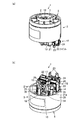
図2(a)および図2(b)において、1は電動送風機を示す。電動送風機1は、ファン2を備え、この実施形態のファン2は遠心ファンである。また、電動送風機1は、ブラシレスモータ3を備える。そして、電動送風機1は、図示されない制御回路により駆動が制御される。
In FIG. 2 (a) and FIG.2 (b), 1 shows an electric blower. The electric blower 1 includes a
ファン2は、図1に示すように、ブラシレスモータ3により回転されることで空気を中心側から外周側へと押し出すものである。ファン2は、ブラシレスモータ3とは反対側にファン翼4を複数備えている。ファン2は、ファン翼4側がファンカバー5により覆われている。ファンカバー5は、円筒状に形成され、ファン2から押し出された空気をブラシレスモータ3へと導く風路6がファン2との間に形成されている。また、ファンカバー5には、ファン2の中央部を露出させる吸気口7が開口されている。
As shown in FIG. 1, the
ブラシレスモータ3は、本実施形態では例えば単相2極のものである。ブラシレスモータ3は、スピンドル10を備えている。また、ブラシレスモータ3は、スピンドル10を回転可能に保持するベアリング11を備えている。また、ブラシレスモータ3は、スピンドル10を回転させるステータ12を備えている。
In this embodiment, the
スピンドル10は、回転磁極を形成するものである。スピンドル10は、出力軸であるシャフト16を備えている。また、スピンドル10は、シャフト16に配置された磁石部17を備えている。
The
図1に示すように、シャフト16は、上下方向に沿って配置されている。シャフト16の上端部は、フレーム14から突出している。また、シャフト16の下端部には、ファン2が一体的に取り付けられている。
As shown in FIG. 1, the
磁石部17は、永久磁石により円筒状に形成され、中央部にシャフト16が固着されている。磁石部17は、シャフト16に対して同軸状又は略同軸状に配置されている。磁石部17は、ファン2の配置と逆であるシャフト16の上端部寄りに配置されている。磁石部17には、回転方向に互いに異なる極性を有する磁極が隣接して形成されている。したがって、磁石部17には、回転方向にN極とS極とが交互に配置されて対をなしている。磁石部17は、ネオジムボンド磁石、又はネオジム焼結磁石等により形成されている。一方、ネオジムボンド磁石は加熱により熱減磁を生じやすいものの、この実施形態の磁石部17は、ネオジムボンド磁石により形成されている。
The
ベアリング11は、複数、例えば一対配置されている。各ベアリング11は、シャフト16を回転自在に保持している。各ベアリング11は、磁石部17に対してそれぞれ下側に配置されている。一対のベアリング11は、シャフト16の軸方向に互いに離れて配置されている。また、一対のベアリング11は、円筒状のスリーブ18に保持された状態でフレーム14に対して固定されている。一対のベアリング11は、スリーブ18の両端部に位置している。
A plurality of, for example, a pair of
図2(a)および図2(b)に示すように、ステータ12は、スピンドル10を回転させる固定磁極を構成するものである。ステータ12は、ステータコア21を備えている。ステータ12は、磁石部17の周囲に磁極を形成するコイル22を備えている。また、ステータ12は、コイル22と制御回路とを電気的に接続する端子23を備えている。さらに、ステータ12は、コイル22および端子23をステータコア21に対して絶縁する絶縁体であるステータ絶縁24を備えている。
As shown in FIGS. 2A and 2B, the
ステータコア21は、コイル22により磁極が形成される偶数、本実施形態では2つのティース21aを備えている。一対のティース21aは、径方向に沿って延び、磁石部17の周囲に位置している。また、一対のティース21aには、コイル22により互いに極性が異なる磁極が形成される。さらに、一対のティース21aの終端部は、磁石部17に対して磁気を作用させる磁気作用面となっている。一方のティース21aの磁気作用面は、磁石部17の約半分の周面に対向し、他方のティース21aの磁気作用面は、磁石部17の残りの約半分側の周面に対向している。また、一対のティース21aの各磁気作用面と磁石部17の外周面との間には、僅かな間隙が形成されている。
The
ブラシレスモータ3は、センサ基板13を備えている。センサ基板13は、スピンドル10の磁石部17の磁極の極性を検出することによってスピンドル10の回転位置又は回転角度を検出するもので、例えば位置検出手段としてホールIC等を備えている。センサ基板13は、例えばステータ12の上側に絶縁された状態で重ねられ、例えばねじ等の基板固定部材26によりステータ12とフレーム14に対して固定されている。
The
また、ブラシレスモータ3は、構造体であるフレーム14を備えている。フレーム14は、シャフト16のファン2と磁石部17との間の部分を包囲し、ファン2の回転により生じる気流を磁石部17側へ案内する。フレーム14は、例えば合成樹脂や金属等の部材により、円筒状に形成されている。フレーム14は、図1に示すように、例えば外郭をなす外壁部28と、外壁部28の内方に位置する支持部29と、外壁部28と支持部29とを連結する整流部30とを備えている。そして、フレーム14に対してベアリング11およびステータ12が固定され、スピンドル10がファン2とともにフレーム14に対して回転可能となっている。
The
外壁部28は、円筒状に形成されている。外壁部28は、例えば電動送風機1の最外郭をなしている。外壁部28は、上下方向に沿って軸方向を有している。外壁部28の下端部には、ファンカバー5の上端部が内挿されて固着されている。
The
支持部29は、ステータ12およびセンサ基板13を支持するとともに、ベアリング11が支持されている。支持部29は、外壁部28の内径よりも小さい外径を有する円形状に形成されている。また、支持部29の外周部には、ファン2とは反対側に向かって湾曲する導風部32が形成されている。さらに、支持部29の下部には、ファン2の一部が挿入される凹部33がファン2に対向する位置に形成されている。また、支持部29の中央部には、ベアリング11を保持するベアリング保持部34が形成されている。さらに、支持部29には、ステータ12およびセンサ基板13が基板固定部材26により固定される固定部35が配置されている。
The
導風部32は、ファンカバー5の外周近傍の位置に対向しているとともに、上方に向かって滑らかに湾曲して形成されている。導風部32は、例えば支持部29の全周に連続して形成されている。また、導風部32は、風路6の壁の一部をなし、ファン2の回転により押し出された空気を支持部29の上側に導くように形成されている。
The
凹部33は、ファン2の外径よりも僅かに大きい円形状に形成されている。
The
ベアリング保持部34は、支持部29の中央部に円筒状に形成され、ファン2に対して反対側に向かって突出している。また、ベアリング保持部34は、外壁部28と同軸状に形成されている。そして、ベアリング保持部34は、内挿されたスリーブ18を介して一対のベアリング11を保持している。
The
固定部35は、支持部29のファン2に対して反対側にボス状に突出している。固定部35は、ベアリング保持部34よりも径寸法が小さく、かつ、ベアリング保持部34よりも上方まで突出している。また、固定部35は、例えば一対形成され、ベアリング保持部34を挟んで位置している。
The fixed
整流部30は、フィン状に形成されている。整流部30は、外壁部28の内周面と支持部29の外縁部とを連結している。また、整流部30は、導風部32と外壁部28との間に亘って形成されている。さらに、整流部30は、周方向に複数、等間隔、又は略等間隔に配置され、互いに離れている。このため、外壁部28と導風部32と整流部30との間に、ファン2の回転により生じる気流AFが通過する空隙Gが形成される。空隙Gは、周方向に複数形成され、それぞれ風路6と連通している。各空隙Gは、フレーム14の外周近傍に配置されている。
The rectifying
ブラシレスモータ3は、ファン2の回転により生じる気流AFを磁石部17側へ案内するガイド部15を備えている。ガイド部15は、ファン2の回転により生じて空隙Gを通過した気流AFを、磁石部17を冷却するようにスピンドル10側に向かって導くものである。ガイド部15は、気流AFが空隙Gを通過した位置に形成されている。ガイド部15は、板状に形成され、ファン2側が平面状のガイド面15aとなっている。また、ガイド部15は、本実施形態において、フレーム14に配置してもよく、フレーム14と一体に形成されてもかまわない。ガイド部15の始端部はフレーム14に固定され、終端部はファン2と磁石部17との間に位置している。図1に示すように、ガイド部15の始端部はフレーム14の外壁部28に固定され、終端部はフレーム14の外壁部28の内周面からスピンドル10に向かって突出している。また、ガイド部15の終端部は、軸方向から見て、空隙Gに対してスピンドル10側に延出されている。また、ファン2側から見る場合、ガイド部15の始端部は、フレーム14の外壁部28に対して非鋭角状に傾斜されている。すなわち、ガイド部15の始端部とフレーム14の外壁部28とのなす角度θは90°以上である。本実施形態において、ガイド部15の始端部は、フレーム14の外壁部28に対して直角、又は略直角に傾斜されている。したがって、ガイド部15は、径方向に沿って延びて形成されている。また、ガイド部15は、本実施形態において、フレーム14の外壁部28からスピンドル10側に向かって突出するフランジ状に形成されている。
The
制御回路は、例えばインバータ回路を含むドライバと、ドライバを制御する制御部とを備え、各端子23およびセンサ基板13と電気的に接続されている。そして、制御回路は、ドライバによってコイル22の巻線に流れる電流の向きや通電時間を制御することで、各コイル22を介してステータ12のステータコア21の各ティース21aにそれぞれ生じさせる磁極を時間毎に切り換えるように構成されている。
The control circuit includes, for example, a driver including an inverter circuit and a control unit that controls the driver, and is electrically connected to each terminal 23 and the
次に、第1の実施形態の電動送風機1の動作について説明する。 Next, the operation of the electric blower 1 of the first embodiment will be described.
電動送風機1は、センサ基板13によりスピンドル10の回転位置を検出しつつ、スピンドル10の回転位置に応じて、制御回路により各コイル22の巻線に流れる電流の向きおよび通電時間を制御することで、ステータ12の各ティース21aに順次磁極を形成し、これら磁極とスピンドル10の磁石部17の磁極との反発・吸引によってスピンドル10を回転させる。スピンドル10のシャフト16に接続されたファン2が回転し、ファン2の回転により発生した負圧によって、空気が吸気口7から電動送風機1に吸い込まれる。
The electric blower 1 detects the rotational position of the
そして、吸気口7から吸い込まれた空気は、ファン2のファン翼4によりファン2の周囲へと整流されつつ風路6を通過し、フレーム14の導風部32から空隙Gへと導かれ、整流部30により整流されながら空隙Gを通過してブラシレスモータ3へと流れ込む気流AFとなる。この後、気流AFはガイド部15のガイド面15aに沿ってスピンドル10側へと導かれ、ステータ12のステータコア21のティース21aと磁石部17との間の間隙を通過することで、磁石部17を冷却しながらブラシレスモータ3のフレーム14内を通過して各コイル22および各端子23を冷却しつつ排気される。ガイド面15aは磁石部17より上流側となる。
Then, the air sucked from the
従来技術では、空隙Gを通過した後の気流AFは、そのままでは大部分がフレーム14の外周近傍を通過し、中央のスピンドル10に位置する磁石部17の冷却が効率的に行われないこととなる。そこで、本実施形態では、磁石部17を冷却するように気流AFを導くガイド部15を形成することで、気流AFを磁石部17に吹き付けて冷却効率を向上できるので、ブラシレスモータ3の入力を低下させずに磁石部17の減磁を抑制できる。したがって、磁石部17の温度上昇に起因する減磁の発生による電動送風機1の性能低下を抑制できる。
In the prior art, most of the airflow AF after passing through the gap G passes through the vicinity of the outer periphery of the
また、ガイド部15の終端部がファン2よりも磁石部17の磁石面に近い側に位置するため、ガイド部15により導かれた気流AFを磁石部17に効率よく当てることができ、磁石部17を効率よく冷却できる。
Further, since the terminal portion of the
さらに、ガイド部15の終端部が空隙Gよりもスピンドル10側に延出されていることで、ガイド部15の終端部側を通過して磁石部17へと向かわずに直進する気流AFを抑制し、空隙Gを通過した気流AFをガイド部15で確実に受けることができ、ガイド部15により導かれる気流AFを磁石部17へと確実に向かわせることができ、磁石部17を効率よく冷却できる。
Furthermore, since the terminal portion of the
また、ファン2側から見て、ガイド部15の始端部をフレーム14に対して非鋭角状としているため、ファン2側に向かって気流AFが逆流しにくく、乱流の発生を抑制でき、スピンドル10側に向かって円滑に気流AFを導くことができる。
In addition, since the starting end of the
さらに、ガイド部15をフレーム14の外壁部28からスピンドル10側に向かって突出するフランジ状とすることで、ガイド部15がある場所とない場所とを生じさせず、外周側からスピンドル10側に向かって均一に気流AFを送り込ませることができ、冷却効率をより向上できる。
Furthermore, the
さらにまた、ガイド部15をフレーム14と一体に形成する場合、接着剤やねじ等でガイド部15をフレーム14等の部品に取り付ける構成と比較して剛性を向上でき、振動値を増加させにくい。
Furthermore, when the
また、ネオジムボンド磁石は高性能磁石のなかでも自由な成形が可能で、製造コストが安価であるものの、磁石粉と樹脂材を混合し成形固化させる製造方法の関係上、材料特性が近い焼結磁石よりも、樹脂材が含まれることで耐熱温度が低く、不純物が多いため減磁が発生しやすい。そこで、本実施形態では、磁石部17を効率よく冷却できることにより、磁石部17をネオジムボンド磁石により形成しても温度上昇による減磁を発生させにくくでき、製品仕様の制限を抑制して、温度上昇に起因する減磁による電動送風機1の性能の低下を抑制できる。
In addition, neodymium bonded magnets can be molded freely among high-performance magnets and are inexpensive to manufacture. However, due to the manufacturing method of mixing and solidifying magnet powder and resin material, sintering has similar material properties. Since the resin material is included rather than the magnet, the heat-resistant temperature is low, and since there are many impurities, demagnetization is likely to occur. Therefore, in the present embodiment, since the
(第2の実施形態)
次に、第2の実施形態を、図3を参照して説明する。なお、上記第1の実施形態と同様の構成および作用については、同一符号を付してその説明を省略する。
(Second Embodiment)
Next, a second embodiment will be described with reference to FIG. In addition, about the structure and effect | action similar to the said 1st Embodiment, the same code | symbol is attached | subjected and the description is abbreviate | omitted.
本実施形態のガイド部15の終端部は、軸方向において、磁石部17と磁石部17に近い側のベアリング11との間に位置している。また、ガイド部15の終端部は、ベアリング11側の磁石部17の端面17aと等しい、又は略等しい位置に配置されている。さらに、ガイド部15の終端部は、フレーム14のベアリング保持部34の外周よりもスピンドル10側に接近する位置まで延びている。また、ガイド部15は、磁石部17側のフレーム14の端部近傍に位置している。
The end portion of the
そして、ファン2の回転により発生した負圧によって吸気口7から吸い込まれた空気は、ファン2のファン翼4によりファン2の周囲へと整流されつつ風路6を通過し、フレーム14の導風部32から空隙Gへと導かれ、整流部30により整流されながら空隙Gを通過してブラシレスモータ3へと流れ込む気流AFとなる。この後、気流AFはガイド部15のガイド面15aに沿ってスピンドル10側へと導かれる。
The air sucked from the
このとき、ガイド部15の終端部は、軸方向において、磁石部17と磁石部17に近い側のベアリング11との間に位置していることにより、ガイド部15によって導かれる気流AFが磁石部17に近い側のベアリング11側から磁石部17へと送り込まれることとなる。このため、磁石部17と磁石部17の外周面に対向するステータコア21のティース21aとの間の狭い間隙に気流AFを入り込ませやすくなり、磁石部17をより効果的に冷却可能となる。
At this time, the terminal portion of the
また、ガイド部15の終端部が、ベアリング11側の磁石部17の端面17aと等しい、又は略等しい位置に配置されているので、ガイド部15の終端部側を通過した気流AFを、そのままベアリング11側の磁石部17の端面17aの位置へと送り込むことができ、磁石部17をより効果的に冷却可能となる。
Further, since the end portion of the
さらに、ガイド部15の終端部は、フレーム14のベアリング保持部34の外周よりもスピンドル10側に接近する位置まで延びているので、ガイド部15が、磁石部17に対して、より接近した位置へと気流AFを導くことができ、磁石部17に対して気流AFをより確実に送り込むことができる。
Further, since the terminal portion of the
(第3の実施形態)
次に、第3の実施形態を、図4を参照して説明する。なお、上記各実施形態と同様の構成および作用については、同一符号を付してその説明を省略する。
(Third embodiment)
Next, a third embodiment will be described with reference to FIG. In addition, about the structure and effect | action similar to said each embodiment, the same code | symbol is attached | subjected and the description is abbreviate | omitted.
本実施形態のガイド部15の終端部は、軸方向において、磁石部17と磁石部17に近い側のベアリング11との間に位置し、かつ、導いた気流AFが磁石部17に対し直接吹き付けられる位置に配置されている。具体的に、ガイド部15は、始端部がファン2側から見てフレーム14の外壁部28に対して鈍角状に形成されているとともに、ガイド面15aの延長面が、ベアリング11側の磁石部17の端面17aの延長面と交差する位置に配置されている。すなわち、ファン2側から見てガイド部15の始端部とフレーム14の外壁部28とのなす角度θは90°より大きい。ガイド部15は、始端部から終端部に向かって、上方に傾斜するように形成されている。また、ガイド部15の終端部は、フレーム14のベアリング保持部34の外周よりもスピンドル10側に接近する位置まで延びている。さらに、ガイド部15のガイド面15aとは反対側の面とフレーム14の外壁部28との間には、断面三角形状のスペースSが形成されている。スペースSには、図示しない他の部品が配置可能となっている。
The end portion of the
そして、ファン2の回転により発生した負圧によって吸気口7から吸い込まれた空気は、ファン2のファン翼4によりファン2の周囲へと整流されつつ風路6を通過し、フレーム14の導風部32から空隙Gへと導かれ、整流部30により整流されながら空隙Gを通過してブラシレスモータ3へと流れ込む気流AFとなる。この後、気流AFはガイド部15のガイド面15aに沿ってスピンドル10側へと導かれる。
The air sucked from the
このとき、ファン2側から見て、ガイド部15の始端部がフレーム14に対して鈍角状に傾斜しているので、空隙Gを通過した気流AFがガイド部15のガイド面15aに沿って、スピンドル10側に向かって徐々に方向を変えられながら流れていく。そのため、空隙Gを通過した気流AFがガイド部15に強く吹き付けられたり、ガイド部15によって急激に流れる方向を変えられたりすることがないので、乱流が発生しにくくなり、磁石部17をより効率よく冷却できる。
At this time, since the starting end portion of the
また、ガイド部15が径方向に対しても傾斜しているので、ガイド部15が径方向と略平行に形成されている構成よりも、ガイド部15によって導かれる気流AFを磁石部17に近い側のベアリング11側から磁石部17の端面17a側へと、より効率よく送り込むことができ、磁石部17と磁石部17の外周面に対向するステータコア21のティース21aとの間の狭い間隙に気流AFを入り込ませやすくなるため、磁石部17をより効果的に冷却可能となる。
Further, since the
さらに、ガイド部15がフレーム14に対して鈍角状に傾斜していることで、ガイド部15の背後のスペースSに他の部品を配置可能となり、省スペース化につながり、電動送風機1の搭載製品の小型化が可能になる。
Furthermore, since the
(第4の実施形態)
次に、第4の実施形態を、図5を参照して説明する。なお、上記各実施形態と同様の構成および作用については、同一符号を付してその説明を省略する。
(Fourth embodiment)
Next, a fourth embodiment will be described with reference to FIG. In addition, about the structure and effect | action similar to said each embodiment, the same code | symbol is attached | subjected and the description is abbreviate | omitted.
本実施形態のブラシレスモータ3は、単相4極のものである。ステータ12には、ステータコア21のティース21aが4つ形成されている。各ティース21aは、それぞれ放射状に径方向に沿って延びている。また、各ティース21aには、コイル22が取り付けられており、コイル22によって各ティース21aに磁極が形成される。磁石部17の周囲には、互いに異なる極性の磁極が周方向に交互に配置される。また、ガイド部15は、周方向に隣接するコイル22間の磁石部17よりファン2側に配置されている。したがって、ガイド部15は、周方向に互いに離れて4つ形成されている。また、この実施形態では、ガイド部15の始端部がフレーム14に固定され、終端部はコイル22間のファン2側の磁石部17の磁石面に位置している。
The
そして、ファン2の回転により発生した負圧によって吸気口7から吸い込まれた空気は、ファン2のファン翼4によりファン2の周囲へと整流されつつ風路6を通過し、フレーム14の導風部32から空隙Gへと導かれ、整流部30により整流されながら空隙Gを通過してブラシレスモータ3へと流れ込む気流AFとなる。この後、気流AFはガイド部15のガイド面15aに沿ってスピンドル10側へと導かれる。
The air sucked from the
このとき、気流AFが空隙Gを通過した位置に、磁石部17を冷却するように気流AFを導くガイド部15を形成する等、上記各実施形態と同様の構成を有することにより、上記各実施形態と同様の作用効果を奏することができる。
At this time, each of the above-described embodiments has the same configuration as each of the above-described embodiments, such as forming a
また、ガイド部15をコイル22間に配置したので、ガイド部15により導かれた気流AFがコイル22により阻害されにくく、磁石部17をより確実に冷却できるとともに、コイル22間のスペースを利用して、ガイド部15を効率よく配置できる。
In addition, since the
なお、上記各実施形態において、ガイド部15は、フレーム14と別体で形成されていてもよいし、フレーム14の内部に位置する他の構造体や部品等と一体に形成されていてもよい。
In each of the above-described embodiments, the
本発明のいくつかの実施形態を説明したが、これらの実施形態は、例として提示したものであり、発明の範囲を限定することは意図していない。これら新規な実施形態は、その他の様々な形態で実施されることが可能であり、発明の要旨を逸脱しない範囲で、種々の省略、置き換え、変更を行うことができる。これら実施形態やその変形は、発明の範囲や要旨に含まれるとともに、特許請求の範囲に記載された発明とその均等の範囲に含まれる。 Although several embodiments of the present invention have been described, these embodiments are presented by way of example and are not intended to limit the scope of the invention. These novel embodiments can be implemented in various other forms, and various omissions, replacements, and changes can be made without departing from the scope of the invention. These embodiments and modifications thereof are included in the scope and gist of the invention, and are included in the invention described in the claims and the equivalents thereof.
1 電動送風機
2 ファン
3 ブラシレスモータ
10 スピンドル
11 ベアリング
14 フレーム
15 ガイド部
16 シャフト
17 磁石部
22 コイル
28 外壁部
1
10 spindle
11 Bearing
14 frames
15 Guide section
16 shaft
17 Magnet part
22 coils
28 Exterior wall
Claims (11)
シャフトと、前記シャフトに配置された磁石部とを有し、前記シャフトに配置された前記ファンとともに回転するスピンドルと、
前記シャフトの前記ファンと前記磁石部との間の部分を包囲し、前記ファンの回転により生じる気流を前記磁石部側へ案内するフレームと、
前記気流を、前記磁石部を冷却するように導くガイド部と、
を具備したことを特徴とするブラシレスモータ。 A brushless motor that rotates a fan,
A spindle having a shaft and a magnet portion disposed on the shaft, and rotating with the fan disposed on the shaft;
A frame that surrounds a portion of the shaft between the fan and the magnet portion and guides an airflow generated by rotation of the fan to the magnet portion side;
A guide portion that guides the airflow to cool the magnet portion;
A brushless motor comprising:
ことを特徴とする請求項1記載のブラシレスモータ。 The brushless motor according to claim 1, wherein a start end portion of the guide portion is fixed to the frame, and a terminal end portion is disposed between the magnet portion and the fan.
前記ガイド部の終端部は、前記磁石部と前記磁石部に近い側の前記ベアリングとの間に位置している
ことを特徴とする請求項1又は2記載のブラシレスモータ。 A bearing for rotatably supporting the spindle;
The brushless motor according to claim 1, wherein an end portion of the guide portion is located between the magnet portion and the bearing on a side close to the magnet portion.
ことを特徴とする請求項1ないし3いずれか一記載のブラシレスモータ。 4. The brushless motor according to claim 1, wherein an end portion of the guide portion extends toward the spindle.
ことを特徴とする請求項1記載のブラシレスモータ。 The brushless motor according to claim 1, wherein the guide portion is inclined at a non-acute angle with respect to the frame when viewed from the fan side.
ことを特徴とする請求項5記載のブラシレスモータ。 The brushless motor according to claim 5, wherein the guide portion is inclined at an obtuse angle with respect to the frame when viewed from the fan side.
ことを特徴とする請求項1ないし6いずれか一記載のブラシレスモータ。 The brushless motor according to any one of claims 1 to 6, wherein the guide portion is formed in a flange shape protruding from the outer wall portion of the frame toward the spindle side.
前記ガイド部は、前記コイル間の前記磁石部より前記ファン側に配置されている
ことを特徴とする請求項1ないし6いずれか一記載のブラシレスモータ。 Comprising a plurality of coils forming magnetic poles around the magnet portion;
The brushless motor according to any one of claims 1 to 6, wherein the guide portion is disposed on the fan side with respect to the magnet portion between the coils.
ことを特徴とする請求項1ないし8いずれか一記載のブラシレスモータ。 The brushless motor according to any one of claims 1 to 8, wherein the guide portion is formed integrally with the frame.
ことを特徴とする請求項1ないし9いずれか一記載のブラシレスモータ。 The brushless motor according to any one of claims 1 to 9, wherein the magnet portion is formed of a neodymium bonded magnet.
前記ファンを回転させる請求項1ないし10いずれか一記載のブラシレスモータと、
を具備したことを特徴とする電動送風機。 With fans,
The brushless motor according to any one of claims 1 to 10, wherein the fan is rotated;
An electric blower comprising:
Priority Applications (1)
| Application Number | Priority Date | Filing Date | Title |
|---|---|---|---|
| JP2018076084A JP2019187111A (en) | 2018-04-11 | 2018-04-11 | Brushless motor and electric blower |
Applications Claiming Priority (1)
| Application Number | Priority Date | Filing Date | Title |
|---|---|---|---|
| JP2018076084A JP2019187111A (en) | 2018-04-11 | 2018-04-11 | Brushless motor and electric blower |
Publications (1)
| Publication Number | Publication Date |
|---|---|
| JP2019187111A true JP2019187111A (en) | 2019-10-24 |
Family
ID=68337815
Family Applications (1)
| Application Number | Title | Priority Date | Filing Date |
|---|---|---|---|
| JP2018076084A Pending JP2019187111A (en) | 2018-04-11 | 2018-04-11 | Brushless motor and electric blower |
Country Status (1)
| Country | Link |
|---|---|
| JP (1) | JP2019187111A (en) |
-
2018
- 2018-04-11 JP JP2018076084A patent/JP2019187111A/en active Pending
Similar Documents
| Publication | Publication Date | Title |
|---|---|---|
| US8648514B2 (en) | Rotary electric motor and blower that uses the same | |
| JP6718365B2 (en) | Electric blower and vacuum cleaner | |
| EP3290716A1 (en) | Centrifugal blower and cleaner | |
| US8760016B2 (en) | Electric machine with enhanced cooling | |
| US9564787B2 (en) | Motor including housing structure with through holes | |
| EP3760877B1 (en) | Electric blower, electric vacuum cleaner and hand dryer | |
| CN101263642A (en) | motor with permanent magnets | |
| JP7090767B2 (en) | Motors, blowers, vacuum cleaners and hand dryers | |
| EP3760878B1 (en) | Electric blower, electric vacuum cleaner and hand dryer | |
| JP6791692B2 (en) | Electric blower | |
| US11894721B2 (en) | Stator, electric motor, vacuum cleaner, and hand drying device | |
| TW201251273A (en) | Stator and cooling fan with the same | |
| CN105703495A (en) | Single-phase brushless motor | |
| EP3761488A1 (en) | Motor, electric blower, electric vacuum cleaner and hand dryer | |
| JP7190368B2 (en) | Brushless motor and electric blower | |
| JP6796465B2 (en) | Electric blower and vacuum cleaner | |
| JP6791691B2 (en) | Electric blower | |
| JP6903036B2 (en) | Electric blower and vacuum cleaner equipped with it | |
| JP2019187111A (en) | Brushless motor and electric blower | |
| JP2020054067A (en) | Electric blower and vacuum cleaner using the same | |
| JPH0487547A (en) | Brushless fan motor | |
| JP4217790B2 (en) | Single phase brushless DC motor | |
| CN118783666A (en) | Rotor and electric motor components | |
| JP3193162U (en) | Brushless motor | |
| JP2017066982A (en) | Electric air blower |