JP2019190098A - Electric driven hydraulic shovel - Google Patents
Electric driven hydraulic shovel Download PDFInfo
- Publication number
- JP2019190098A JP2019190098A JP2018082927A JP2018082927A JP2019190098A JP 2019190098 A JP2019190098 A JP 2019190098A JP 2018082927 A JP2018082927 A JP 2018082927A JP 2018082927 A JP2018082927 A JP 2018082927A JP 2019190098 A JP2019190098 A JP 2019190098A
- Authority
- JP
- Japan
- Prior art keywords
- cable
- opening
- shaft
- holding member
- hydraulic excavator
- Prior art date
- Legal status (The legal status is an assumption and is not a legal conclusion. Google has not performed a legal analysis and makes no representation as to the accuracy of the status listed.)
- Granted
Links
Images
Landscapes
- Component Parts Of Construction Machinery (AREA)
Abstract
Description
本発明は、電動機で油圧ポンプを駆動する電気駆動式油圧ショベルに関し、特に、後端旋回半径を抑えても旋回体の後端よりも後方にケーブル保持部材が突出せず、後端旋回半径を抑えるメリットを損なわない電気駆動式油圧ショベルに係る。 The present invention relates to an electrically driven hydraulic excavator that drives a hydraulic pump with an electric motor, and in particular, even if the rear end turning radius is suppressed, the cable holding member does not protrude behind the rear end of the revolving structure, and the rear end turning radius is increased. The present invention relates to an electrically driven hydraulic excavator that does not impair the merit to suppress.
トンネル坑内や屋内、立坑、地下等の現場で掘削作業等を行う場合、排気ガスの出るエンジン駆動式の油圧ショベルに代えて、アクチュエータを駆動する圧油を吐出する油圧ポンプを電動機で駆動する電気駆動式の油圧ショベルが用いられることがある。電気駆動式の油圧ショベルでは外部電源に接続した給電用のケーブルを履帯で踏まないように、アーム状のケーブル保持部材を先端に取り付けた支柱を旋回体の上部に立て、ケーブル保持部材にケーブルを掛けて履帯周辺にケーブルが垂れないようにしている。ケーブル保持部材が支柱に対して回動する構造とし、旋回体の旋回に伴う捩れや引っ張り等のケーブルの負担軽減を図ったものもある(特許文献1等参照)。 When excavation work is performed in tunnel tunnels, indoors, vertical shafts, underground sites, etc., instead of engine-driven hydraulic excavators that emit exhaust gas, an electric motor that drives a hydraulic pump that discharges pressure oil that drives an actuator Driven hydraulic excavators are sometimes used. In an electrically driven hydraulic excavator, a strut with an arm-shaped cable holding member attached to the tip is set up at the top of the revolving unit so that the power supply cable connected to an external power source is not stepped on the crawler track. It is hung so that cables do not hang around the track. In some cases, the cable holding member is configured to rotate with respect to the support column, and the cable burden such as twisting and pulling associated with the turning of the turning body is reduced (see Patent Document 1).
走行体に対して旋回する旋回体を備えた油圧ショベルにあっては、旋回に伴ってケーブルが振り回されないように、ケーブル保持部材を支持する支柱を旋回体の旋回中心付近に配置することが望ましい。また、作業機には作業に伴って掘削反力等が作用するため、作業機により旋回体に作用するモーメント荷重を抑えるべく作業機の基部も旋回体の旋回中心付近に配置することが望ましい。しかしケーブル保持部材を支える支柱と作業機の基部とを旋回中心付近に配置すると、制限一杯までブーム上げ動作をして作業機を後傾させたときに作業機のブームが支柱に干渉する恐れがある。そのため、特許文献1においても、作業機に干渉しないように支柱は根元部分に対して後方に傾斜させてある。
In a hydraulic excavator provided with a revolving structure that revolves with respect to the traveling body, a support that supports the cable holding member may be disposed near the revolving center of the revolving structure so that the cable is not swung with the turning. desirable. Further, since excavation reaction force acts on the work machine as the work is performed, it is desirable that the base of the work machine is also arranged near the turning center of the swivel body in order to suppress the moment load acting on the swivel body by the work machine. However, if the support for supporting the cable holding member and the base of the work implement are arranged near the center of rotation, the boom of the work implement may interfere with the support when the work implement is tilted backwards by raising the boom to the full limit. is there. Therefore, also in
同文献の油圧ショベルは標準型の油圧ショベルであり旋回中心から旋回体の後端までの距離(以下、後端旋回半径)に余裕があるため、上記のように支柱を後傾させてもケーブル保持部材が旋回体の後端よりも後方に突出することはない。しかし、比較的小型の機種では後端旋回半径が短く設定してあるため、作業機との干渉を避けて支柱を後傾させると旋回体の後端よりも後方にケーブル保持部材が突出する可能性がある。旋回体の後端からケーブル保持部材が突出すると、旋回体の旋回時にケーブル保持部材が周囲の障害物に干渉し易くなり、狭所で旋回動作が行える比較的小型の機種のメリットが損なわれてしまう。 The hydraulic excavator in this document is a standard type hydraulic excavator, and there is a margin in the distance from the turning center to the rear end of the revolving structure (hereinafter referred to as the rear end turning radius). The holding member does not protrude rearward from the rear end of the revolving unit. However, since the rear end turning radius is set to be shorter in relatively small models, the cable holding member can protrude rearward from the rear end of the revolving structure when the support column is tilted backward to avoid interference with the work equipment. There is sex. When the cable holding member protrudes from the rear end of the swivel body, the cable holding member easily interferes with surrounding obstacles when turning the swivel body, and the merit of a relatively small model that can turn in a narrow place is lost. End up.
本発明の目的は、後端旋回半径を抑えても旋回体の後端よりも後方にケーブル保持部材が突出せず、後端旋回半径を抑えるメリットを損なわない電気駆動式油圧ショベルを提供することにある。 An object of the present invention is to provide an electric drive hydraulic excavator in which the cable holding member does not protrude rearward from the rear end of the revolving structure even if the rear end turning radius is suppressed, and the merit of suppressing the rear end turning radius is not impaired. It is in.
上記目的を達成するために、走行体、前記走行体の上部に旋回可能に設けた旋回体、前記旋回体に取り付けた作業機、前記作業機を駆動する油圧アクチュエータ、前記油圧アクチュエータを駆動する圧油を吐出する油圧ポンプ、前記油圧ポンプを駆動する電動機、前記電動機に供給する電力を調整する制御盤、前記制御盤と外部電源とを接続するケーブル、前記旋回体の上部に立設した支柱、及び前記ケーブルを保持するケーブルブラケットを備え、前記ケーブルブラケットは、前記支柱の上部に立設されて上下に延びる軸、及び前記軸を中心に回転可能に設けられたケーブル保持部材を有する電気駆動式油圧ショベルにおいて、前記ケーブル保持部材は、前記軸に対して前記旋回体の後端側で開口する第1の開口と、前記軸を挟んで前記第1の開口と反対側で開口する第2の開口とを備え、上方に向かって凸の弓形に形成されたケーブル挿通路を有しており、前記外部電源から延びる前記ケーブルが、前記旋回体の後端側から前記第1の開口を介して前記ケーブル挿通路に通され、前記第2の開口から前記軸よりも前方側に取り出されて前記制御盤に接続されるように構成したことを特徴とする。 To achieve the above object, a traveling body, a revolving body provided on the upper part of the traveling body, a working machine attached to the revolving body, a hydraulic actuator that drives the working machine, and a pressure that drives the hydraulic actuator. A hydraulic pump that discharges oil; an electric motor that drives the hydraulic pump; a control panel that adjusts the power supplied to the electric motor; a cable that connects the control panel and an external power source; And a cable bracket for holding the cable, the cable bracket having an axis extending up and down on an upper portion of the support column, and a cable holding member rotatably provided around the axis In the hydraulic excavator, the cable holding member includes a first opening that opens on a rear end side of the revolving unit with respect to the shaft, and the first opening across the shaft. And a second opening that opens on the opposite side of the opening, and has a cable insertion passage formed in an upwardly convex arcuate shape, and the cable extending from the external power source is disposed behind the swivel body It is configured to be passed through the cable insertion path from the end side through the first opening, and to be taken out from the second opening to the front side of the shaft and connected to the control panel. To do.
本発明に係るケーブル保持部材は、ケーブル挿通路の第1の開口が軸に対して旋回体の後端側で開口し、第2の開口が軸を挟んで第1の開口と反対側で開口するように形成されている。そのため、ケーブルの許容曲げ半径に応じてケーブル保持部材の大きさを確保した上で、旋回体の後端側に位置するケーブル挿通路の第1の開口を従来に比べて前方に配置される。よって、後端旋回半径を抑えた比較的小型の油圧ショベルを適用対象としても、旋回体の後端から後方にケーブル保持部材が突出しないようにすることができる。これにより、後端旋回半径を抑えることで旋回体の旋回時に旋回体後端の後方周囲の障害物との干渉を抑制できるという比較的小型機種のメリットが活かせる。 In the cable holding member according to the present invention, the first opening of the cable insertion passage opens on the rear end side of the rotating body with respect to the shaft, and the second opening opens on the opposite side of the first opening across the shaft. It is formed to do. Therefore, after securing the size of the cable holding member according to the allowable bending radius of the cable, the first opening of the cable insertion passage located on the rear end side of the revolving structure is disposed forward compared to the conventional case. Therefore, even if a relatively small hydraulic excavator with a reduced rear end turning radius is applied, the cable holding member can be prevented from protruding backward from the rear end of the rotating body. Accordingly, the advantage of the relatively small model that the interference with the obstacles around the rear of the rear end of the swing body can be suppressed when the swing body is turned by suppressing the rear end turning radius can be utilized.
以下に図面を用いて本発明の実施形態を説明する。 Embodiments of the present invention will be described below with reference to the drawings.
−電気駆動式油圧ショベル−
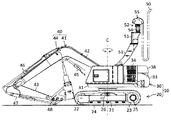
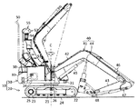
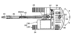
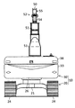
図1は本発明の一実施形態に係る電気駆動式油圧ショベルの全体構成を表す左側面図、図2は右側面図、図3は平面図、図4は後面図である。図2においては後述する作業機40と開閉蓋38の可動範囲を併せて図示してある。図3では後述する支柱51及びケーブル50を図示省略してある。以下の説明において断り書きのない場合は図1中の左方向を前方とする。
-Electric drive excavator-
1 is a left side view showing the overall configuration of an electrically driven hydraulic excavator according to an embodiment of the present invention, FIG. 2 is a right side view, FIG. 3 is a plan view, and FIG. 4 is a rear view. In FIG. 2, a movable range of a
図1〜図4の図に示した電気駆動式油圧ショベル(以下、油圧ショベル)は、油圧ポンプを駆動する原動機としてエンジン(内燃機関)に代えて電動機(電動モータ)を搭載し、外部電源(不図示)から供給される電力で電動機を駆動する作業機械である。この油圧ショベルは、車体10及びこの車体10に取り付けた作業機(フロント作業機)40を備えている。車体10は、走行体20及び旋回体30を含んで構成されている。
The electrically driven hydraulic excavator (hereinafter, hydraulic excavator) shown in FIGS. 1 to 4 includes an electric motor (electric motor) instead of an engine (internal combustion engine) as a prime mover for driving a hydraulic pump, and an external power source ( This is a work machine that drives an electric motor with electric power supplied from an unillustrated). The hydraulic excavator includes a
・走行体
走行体20はホイール式の走行体でも良いが本実施形態ではクローラ式の走行体であり、トラックフレーム21、従動輪(アイドラ)22、駆動輪23、クローラ(履帯)24及び走行駆動装置25を備えている。
-Traveling body The
トラックフレーム21は、図示していないが上方から見てH型に形成されており、左右両側の前部に従動輪22、左右両側の後部に駆動輪23を回転自在に支持している。左右の駆動輪23の軸にはそれぞれ走行駆動装置25の出力軸が連結されている。走行駆動装置25は油圧モータと減速機からなる。クローラ24は左右両側において従動輪22及び駆動輪23に掛け回されている。走行駆動装置25により駆動輪23が駆動されることで、従動輪22及び駆動輪23の間でクローラ24が循環駆動される。
Although not shown, the
・旋回体
旋回体30は旋回輪26を介してトラックフレーム21の上部に旋回可能に設けられており、旋回フレーム31、カウンタウェイト33、動力室34等を備えている。
-Revolving body The revolving
旋回フレーム31は旋回体30のベースフレームであり、旋回輪26を介してトラックフレーム21の上部に設けられており、旋回体30が旋回中心Cを中心にして走行体20に対して旋回可能である。旋回フレーム31には、旋回輪26の付近に旋回モータ(不図示)が搭載されており、旋回モータの出力軸が旋回輪26に設けた歯車と噛み合うことで、走行体20に対して旋回体30が旋回する。旋回モータには電動モータを用いることもできるが、本実施形態では油圧モータが用いてある。
The revolving
本実施形態の油圧ショベルは無線式又は有線式のリモコンによる遠隔操作式の無人機であり、運転室は省略されている。但し運転室を設ける場合もあり、その場合には旋回中心Cに対して左右方向の一方側(本実施形態では左側)にオフセットした位置に配置することができる。カウンタウェイト33は作業機40との重量のバランスをとるための錘であり、旋回フレーム31の後端に設けられている。
The hydraulic excavator according to the present embodiment is a remote-operated drone using a wireless or wired remote controller, and a driver's cab is omitted. However, a cab may be provided, and in that case, the cab can be arranged at a position offset to one side in the left-right direction (left side in the present embodiment) with respect to the turning center C. The
動力室34は作業機40とカウンタウェイト33の間に位置している。この動力室34には、電動機35(図1)や油圧ポンプ36の他、図示していないがオイルクーラ等の熱交換器、油圧ポンプ36から油圧アクチュエータに供給する圧油の流れを制御するバルブユニット等が収容されている。電動機35は原動機であり、油圧ポンプ36は電動機35により駆動され、例えば旋回体30における作業機40の右側に配置した作動油タンク37(図3)の作動油を吸い込んで圧油として吐出する。油圧ポンプ36は電動機35の右側に位置している。作動油タンク37は例えば旋回体30における作業機40の右側で動力室34(油圧ポンプ36)の前側に位置している。エンジン(内燃機関)は、油圧ショベルには搭載されていない。
The
旋回体30の外壁の上面から後面に跨る部分は、動力室34を覆う開閉蓋38を構成している。この開閉蓋38は前端部がヒンジを介して旋回体30の上面の外壁に連結されており、前端部を支点にして後部が上下に回動して動力室34を開閉するようになっている(図2)。本例の油圧ショベルは比較的小型の機種であり、メンテナンス時等に地上に立った作業者が旋回体30の後方から動力室34内の電動機35等にアクセスし易く構成されている。なお、中型以上の比較的大きな機種では旋回体が地上から高い位置にあるため、作業者は旋回体の上に立って動力室の内部にアクセスするのが通常である。従って比較的大型の機種では旋回体の上に立った作業者が前方からアクセスし易いように、一般に動力室の開閉扉は後端を支点にして前部が上下に回動して開閉する。
A portion extending from the upper surface to the rear surface of the outer wall of the revolving
旋回体30には、例えば作業機40の左右方向の片側の位置に制御盤(不図示)が配置されている。エンジン駆動式の油圧ショベルでは作動油タンク37の前側に燃料タンクが配置される場合があるが、本例の油圧ショベルでは燃料タンクが省略されているため、作業機40の右側のスペースに制御盤を設置することができる。また、前述した通り本実施形態においては運転室も省略されているため、作業機40の左側のスペースに制御盤を設置することもできる。この制御盤は、外部電源(不図示)から受電する装置であり、特に図示していないが、必要に応じて外部電源を遮断及び投入するブレーカ、入力された電力の周波数を電気的に調整して出力可能なインバータ装置を備えている。電動機35の回転数に相当する周波数にインバータで調整された電力が、制御盤を介して電動機35に供給されるようになっている。旋回体30の上部には、走行体20との接触による給電用のケーブル50を支持するためのケーブルブラケット52(後述)が取り付けられている。
For example, a control panel (not shown) is disposed on the revolving
・作業機
作業機40は、作業腕41及び作業具であるブレーカ44を含む多関節型のフロント作業機である。作業腕41は、ブーム42、アーム43、ブームシリンダ45、アームシリンダ46及び作業具シリンダ47を備えている。ブーム42は旋回体30の前部に上下方向に回動可能に連結され、アーム43はブーム42の先端に、ブレーカ44はアーム43の先端に、それぞれ回動可能に連結されている。ブームシリンダ45は旋回体30及びブーム42に、アームシリンダ46はブーム42及びアーム43に、それぞれ両端が連結されている。作業具シリンダ47は、基端がアーム43に連結される一方、先端がリンク48を介してアーム43の先端部及びブレーカ44に連結されている。ブームシリンダ45、アームシリンダ46及び作業具シリンダ47はいずれも油圧アクチュエータであり、油圧ポンプ36から吐出される圧油で駆動され、伸縮動作により作業機40を駆動する。作業腕41には、バケット、マグネット、クラムシェルバケット等の他の作業具がブレーカ44に代えて装着され得る。
-Work machine The
−外部電源−
外部電源(不図示)は例えば発電機であり、油圧ショベルとは別に適所に設置されている。外部電源と油圧ショベルとはケーブル50を介して接続される。具体的には、ケーブル50の一端が外部電源の出力部に接続され、他端が油圧ショベルの前述した制御盤に接続される。ケーブル50の長さは油圧ショベルの動作を妨げない程度に設定されている。
−External power source−
An external power source (not shown) is, for example, a generator, and is installed at an appropriate place separately from the hydraulic excavator. The external power source and the hydraulic excavator are connected via a
−ケーブル保持機構−
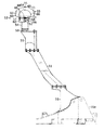
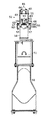
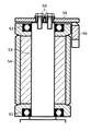
図5は本例の油圧ショベルに備えられた支柱及びケーブルブラケットの右側面図、図6は後面図、図7は図6のVII−VII線による矢視断面図である。ケーブルブラケット52はケーブル50を保持するものであり、旋回体30の上部に立設した支柱51により支持されている。支柱51とケーブルブラケット52とでケーブル保持機構を構成する。まず支柱51について説明する。
-Cable holding mechanism-
FIG. 5 is a right side view of a column and a cable bracket provided in the hydraulic excavator of this example, FIG. 6 is a rear view, and FIG. 7 is a cross-sectional view taken along line VII-VII in FIG. The
・支柱51
支柱51は、本例では作業機40のブーム42のフート部を連結するために旋回フレーム31に設けたブラケット部31a(図5)に取り付けられている。ブラケット部31aは旋回中心Cに重ねて配置されており、支柱51の基部は旋回中心Cの近傍(本例では旋回中心Cの後側)に位置している。ここで、ブームシリンダ45を最伸長させて制限一杯までブーム上げ動作をすると、ブーメラン型に屈曲した形状のブーム42の基部側の部分が図2に二点鎖線で示したように鉛直な旋回中心Cを越えて後傾する。以降、図2に二点鎖線で示したブーム42の位置を上限位置と記載する。開閉蓋38は閉じた状態では上面が水平であるが、開くと前縁を支点にして後部が上昇し、同図に示したように上限位置のブーム42の基部側部分に上面が沿う姿勢となる。このような開放状態の開閉蓋38と上限位置の作業機40(ブーム42)との間には、同図のように左右から見ると上方に向かって後方に傾斜した細長い隙間が生じる。支柱51はこの細長い傾斜した隙間を通るように後傾させ、作業機40や開閉蓋38の可動領域に干渉しないようにレイアウトしてある。続けてケーブルブラケット52について説明する。
・
The
・ケーブルブラケット52
ケーブルブラケット52は、軸53、外筒54、ケーブル保持部材55、ストッパ56及び緩衝部材57を備えている。
・
The
軸53は円柱状に形成された部材であり、支柱51の上部(上端面)に立設されて上下方向に延びている。軸53は支柱51に対して例えば溶接で固定されている。軸53の上端面にはプレート58が複数(本実施形態では3つ)のボルト59により取り付けられている。プレート58は軸53に被せられる外筒54の抜止めとして機能する。プレート58の一部は外筒54の外周面よりも後方に突出している。ボルト59は例えば軸53の中心線を中心とする正多角形(本例では正三角形)の頂点を構成する配置とし、軸53に対するプレート58の取り付け角度が変更できるようにすることが望ましい。
The
外筒54は軸53に被せられ(内部に軸53が通され)、軸53の外周を覆っている。外筒54は上下2箇所でベアリング61(図7)により軸53に対して自転自在に取り付けられている。本実施形態では外筒54が軸53に対して回転する構成を採用しているが、軸53が外筒54とともに回転する構成としても良い。図7では図示省略しているが、外筒54の外周面の上部には半円状のブロックで構成したストライカ62(図5)が溶接等により固定されて設けられている。ストライカ62は外筒54の外周面の例えば半周程度を覆っている。上から見て外筒54が左回りに回転すると外筒54の回転方向(左回り方向)を向いた端面がストッパ56に面接触し、右回りに回転すると外筒54の回転方向(右回り方向)を向いた端面がストッパ56に面接触するように構成されている。
The
ケーブル保持部材55はケーブル50を直接的に支持し保持する部材であり、軸53を中心に回転可能に設けられている。具体的には、ケーブル保持部材55は左右のサイドプレート63、ガイドプレート64及び複数(本例では3つ)のホルダ65を備えている。
The
左右のサイドプレート63はケーブル50の左右を拘束する部材であり、左右から見ると上縁部が上に凸の円弧状の扇型(或いは半円形)の板材で形成されている(図5)。但し、前後から見ると左右のサイドプレート63の下部はそれぞれ左右方向の外側に折れ曲がり水平面を構成している(図6)。ガイドプレート64は左右のサイドプレート63の間に介在して左右のサイドプレート63の対向面に対して溶接等により固定されており、左右のサイドプレート63を連結している。ガイドプレート64は平板を湾曲させて上方に向かって凸の弓形に形成されている。左右から見てガイドプレート64からなる弧の半径はサイドプレート63の上縁からなる弧の半径よりも小さく、かつサイドプレート63の上縁とガイドプレート64とが同心状になるように構成されている(図5)。ガイドプレート64の曲率半径は、ケーブル50の許容曲げ半径よりも大きく設定してある。ホルダ65はC字型の部材であり、C字の開口をガイドプレート64の外周面に向けた姿勢でボルト66によりガイドプレート64に固定されている(図6)。各ホルダ65はガイドプレート64との間に形成される空間をガイドプレート64の弧状の外周面の周方向に開口させる姿勢で取り付けられている。
The left and
上記構成のケーブル保持部材55は、ストライカ62の上部にスペーサ67を挟んで配置され、サイドプレート63の下部の水平面がスペーサ67を介してストライカ62の上端面に複数のボルト68で締結されている。このようにストライカ62を介して外筒54にケーブル保持部材55が固定されている。また、図1、図2、図3〜図6の各図においては、上から見てストライカ62の外周面(円弧)の中央が前方に位置する(軸53の中心線を含み前後に延びる面でストライカ62が左右に等分される)姿勢で外筒54が停止した状態を表している。この状態において、ケーブル保持部材55は前後に延びる(ホルダ65が前後に並ぶ)姿勢となるように構成されている。つまり、外筒54、ストライカ62及びケーブル保持部材55を含み一体に回転する回転体は、各図の状態において左右対称形状となるように形成されている。このとき、3つのホルダ65はガイドプレート64の外周面に沿って所定間隔で配置されており、本例では左右から見て中央のホルダ65がガイドプレート64の頂部に鉛直に取り付けられている(図5)。本実施形態ではガイドプレート64の頂部及び中央のホルダ65は軸53の中心線の延長線上に位置している。従って、ケーブル保持部材55はガイドプレート64の頂部を中心にして回転(自転)する。中央のホルダ65を挟む両側のホルダ65(前側のホルダ65及び後側のホルダ65)は、軸53の中心線(ケーブル保持部材55の自転軸)を互いの間に挟むように配置されている。
The
ここで、ケーブル保持部材55は、上に凸の弓形のケーブル挿通路を有する。本実施形態では、前述したガイドプレート64がケーブル挿通路の底面であり、ホルダ65がケーブル挿通路の側面及び天井面を兼ねている。本実施形態では間隔をあけて複数のホルダ65を配置しているのでケーブル挿通路は間欠的であるが、全体として1本のトンネル状のケーブルの配線経路を構成する。本実施形態の場合、複数のホルダ65が前後に並んだ状態で最も後方に位置するホルダ65の開口がケーブル挿通路の第1の開口であり、最も前方に位置するホルダ65の開口が第2の開口である。ケーブル挿通路の第1の開口は軸53に対して旋回体30の後端側で下向きに開口し、もう1つの第2の開口は軸53を挟んで第1の開口と反対側(つまり作業機40側)で下向きに開口している。本実施形態においては、ケーブル挿通路は軸53の中心線に関して前後対称形状である。外部電源(不図示)から延びるケーブル50が、旋回体30の後端側から第1の開口を介してケーブル挿通路に通され、第2の開口から軸53よりも前方側に取り出されて前述した制御盤に接続される。なお、ケーブル保持部材55の回転を許容すると共に、ケーブル保持部材55の回転に伴ってケーブル50に引っ張り荷重が作用しないように、ケーブル保持部材55と制御盤との間においてケーブル50には適度に弛みが確保してある。
Here, the
ストッパ56はケーブル保持部材55の可動範囲(回転角度)を制限する部材であり、上記プレート58の後端部に溶接等で取り付けられ、プレート58を介して軸53に固定されている。ストッパ56は外筒54の後側に位置し、プレート58から下向きに延びている。具体的には、ストッパ56は、相対的に幅の広い上部56Aと相対的に幅の狭い下部56BからなるT字型のブロック体である(図6)。外筒54が回転して前述したストライカ62がストッパ56の上部56Aの左又は右の側面に干渉することで、ケーブル保持部材55の可動範囲が制限される。図1に示すようにケーブル保持部材55が前後に延びる姿勢を基準とすると、本実施形態ではケーブル保持部材55の可動範囲が左右に任意の設定角度αずつ(例えば50度ずつ計100度程度)に設定されている。前述した通り軸53に対するプレート58の取り付け角度を変更することにより、軸53に対するストッパ56の周方向位置が調整可能である。
The
緩衝部材57はストッパ56とケーブル保持部材55を含む回転体(本例では直接的にはストライカ62)との衝突を和らげる部材であり、ストライカ62におけるストッパ56の下部56Bとの両対向面に設けられている。緩衝部材57は例えば先端に半球状の弾性部材(ゴム等)を設けたネジであり、ストライカ62の端面にねじ込まれて取り付けられ、ストライカ62の端面と弾性体との距離が調整可能である。ストライカ62の端面からの弾性体の突出量は、ストッパ56の上部56Aと下部56Bの段差寸法よりも大きくなるように調整しておく。これにより外筒54が回転する際にストライカ62がストッパ56の上部56Aに接触するのに先行して緩衝部材57の弾性体がストッパ56の下部56Bに接触し、回転体とストッパ56との接触時の衝撃が和らげられる。
The
−動作−
本実施形態に係る油圧ショベルは、代表的にはトンネル坑内や屋内、立坑、地下等の閉鎖的な空間で掘削作業等を行う場面で用いられる。油圧ショベルを運転する場合、まずケーブル50で外部電源(不図示)と油圧ショベルを接続する。その際、ケーブル保持部材55の上記ケーブル挿通路にケーブル50を通し、ケーブル保持部材55と油圧ショベル(制御盤)との間においてケーブル50に適度な弛みを持たせておく。また必要な場合には、軸53に対するプレート58の取り付け角度を変更することにより、軸53に対するストッパ56の周方向位置を外部電源と油圧ショベルの位置関係に応じて調整する。その後、外部電源を運転して油圧ショベルへの電力の供給を開始し、オペレータはリモコン(不図示)を用いて油圧ショベルを適宜操作する。これにより走行体20によって油圧ショベルを移動させたり、作業機40によって掘削作業をしたり、旋回体30を旋回させたりすることができる。
-Operation-
The hydraulic excavator according to the present embodiment is typically used in a scene where excavation work or the like is performed in a closed space such as in a tunnel mine, indoors, a shaft, or underground. When the hydraulic excavator is operated, first, an external power source (not shown) and the hydraulic excavator are connected by the
−効果−
(1)本願出願以前の従来の電気駆動式油圧ショベルでは、油圧ショベルの制御盤とケーブル保持部材との間においてケーブルの動きを抑えるように構成されていた。具体的には、ケーブル保持部材の一端を外筒の外周面に固定し、ケーブル保持部材が一端を中心にして回動する構成である。この場合、ケーブル保持部材の一端ひいてはケーブル挿通路の一方側の開口は、回転中心に近いため回転に伴う変位量が小さい。ケーブルは回転中心の近くでケーブル挿通路からケーブルが取り出され、支柱に沿って制御盤に向かって這い回されるため、ケーブル保持部材が揺動してもケーブル保持部材と制御盤との間におけるケーブルの振れが小さいことが1つのメリットである。
-Effect-
(1) The conventional electrically driven hydraulic excavator prior to the filing of the present application is configured to suppress the movement of the cable between the control panel of the hydraulic excavator and the cable holding member. Specifically, one end of the cable holding member is fixed to the outer peripheral surface of the outer cylinder, and the cable holding member rotates around the one end. In this case, one end of the cable holding member and thus the opening on one side of the cable insertion path are close to the rotation center, so that the amount of displacement accompanying rotation is small. Since the cable is taken out from the cable insertion path near the center of rotation and wound around the post toward the control panel, even if the cable holding member swings, it is not between the cable holding member and the control panel. One advantage is that the cable runout is small.
しかし、ケーブル保持部材にはケーブルの許容曲げ半径よりも大きな曲率半径でケーブルを保持するためのケーブル挿通路が必要であり、ケーブルの太さ等に応じて一定の前後長を要する。そのため、従来の電気駆動式油圧ショベルのようにケーブル保持部材が一端を中心に回動する構成では、旋回中心から旋回体の後端までの距離が短い比較的小型の機種においてはケーブル保持部材が旋回体の後端より後方に突出する場合があった。 However, the cable holding member requires a cable insertion path for holding the cable with a radius of curvature larger than the allowable bending radius of the cable, and requires a certain longitudinal length according to the thickness of the cable. For this reason, in a configuration in which the cable holding member rotates around one end as in a conventional electrically driven hydraulic excavator, the cable holding member is used in a relatively small model in which the distance from the turning center to the rear end of the turning body is short. In some cases, it protrudes backward from the rear end of the revolving structure.
それに対し、本実施形態のケーブル保持部材55は、ケーブル挿通路の第1の開口が軸53に対して旋回体30の後端側で開口し、第2の開口が軸53を挟んで第1の開口と反対側で開口するように形成されている。ケーブル挿通路が回転中心を跨ぐように、従来構成に比べて軸に対してケーブル保持部材55が前方にオフセットした構成である。従って、ケーブル50の許容曲げ半径に応じてケーブル保持部材55の大きさを確保した上で、旋回体30の後端側に位置するケーブル挿通路の第1の開口を従来に比べて前方に配置することができる。よって、後端旋回半径を抑えた比較的小型の油圧ショベルを適用対象としても、旋回体30の後端から後方にケーブル保持部材が突出しないようにすることができる。これにより、後端旋回半径を抑えることで旋回体の旋回時に旋回体後端の後方周囲の障害物との干渉を抑制できるという比較的小型機種のメリットが活かせる。
On the other hand, in the
(2)特に本実施形態においては、軸53に関してケーブル挿通路を前後対称形状に構成したので、ケーブル挿通路の第1の開口と第2の開口の変位量が等しくなる。ケーブル挿通路に保持されたケーブル50も軸53の前後で揺動することになり、軸53を挟んでケーブル50に作用する慣性力のバランスが従来と比較して相殺され、ケーブル50の重量や動きにより軸53に作用する負荷が軽減できる。
(2) Especially in this embodiment, since the cable insertion path is configured in a longitudinally symmetrical shape with respect to the
但し、上記の本質的効果(1)を得る限りにおいては、軸53に関してケーブル挿通路が前後対称形状である必要はなく、軸53の配置が第1の開口及び第2の開口のいずれか一方側に偏った構成であっても良い。但し、ケーブル挿通路を前方にオフセットさせる(第1の開口寄りに軸53を配置する)場合、オフセット量はケーブル保持部材55が作業機40の可動範囲に干渉しない範囲に制限される。ケーブル挿通路を後方にオフセットさせる(第2の開口寄りに軸53を配置する)場合、オフセット量はケーブル保持部材55が旋回体30の後端から後方に突出しない範囲に制限される。
However, as long as the above essential effect (1) is obtained, the cable insertion path does not have to be symmetrical in the longitudinal direction with respect to the
(3)本実施形態では間隔をあけて複数のホルダ65を配置しているので、ケーブル挿通路が間欠的なトンネル状に形成されている。このような間欠的なケーブル挿通路であってもケーブル50を保持する観点では必要十分に機能する。間欠的であるためにケーブル挿通路にケーブル50が通し易い一面もあり、ケーブル挿通路の内部におけるケーブル50の状態が視認できるメリットもある。ガイドプレート64に対するホルダ65の組み付け及び取り外しも容易である。
(3) In the present embodiment, since the plurality of
但し、上記効果(1)を得る限りにおいては、ケーブル挿通路を間欠的構成にする必要は必ずしもなく、例えば左右のサイドプレート63の上縁に跨る円弧状のプレートを設け、ケーブル挿通路を1本の連続したトンネル状に形成しても良い。また、ホルダ65を省略して全面に上部が開放されたスリット状にケーブル挿通路を形成し、単純にガイドプレート64でケーブル50を支持するだけの構成としても良い。
However, as long as the above effect (1) is obtained, the cable insertion path does not necessarily have an intermittent configuration. For example, an arc-shaped plate straddling the upper edges of the left and
(4)仮にケーブル保持部材55が全く自由に回転する構成とすると、旋回体30の旋回動作が繰り返されるうちにケーブル50が捩れる可能性がある。本実施形態においてはストッパ56によりケーブル保持部材55の可動範囲が制限されているので、ケーブル50の捩れを抑制できる。なお、本実施形態ではストッパ56がストライカ62に干渉する構成としたが、ケーブル保持部材55を含んで一体に回転する回転体の一部にストッパ56が干渉すれば、その回転体の可動範囲を制限することができる。ストッパ56の配置や形状、大きさは適宜変更可能である。
(4) If the
(5)緩衝部材57を設けたことによりストライカ62とストッパ56との衝突が和らげられるので、作業時のストッパ56とストライカ62との衝突音が和らげられる。緩衝によりケーブルブラケット52の構成要素の部品の傷みも軽減でき、ケーブルブラケット52のメンテナンスの負担も軽減できる。
(5) Since the collision between the
(6)本実施形態の油圧ショベルは比較的小型であるため、動力室34の開閉蓋38は後部が上下に開閉し、作業者は地面に立って旋回体30の後方から動力室34の内部にアクセスできる。反面、ケーブルブラケット52の支柱51に向かって開閉蓋38が開き、支柱51を設置すべき領域が作業機40と開閉蓋38の可動域に挟まれることになる。そこで本実施形態では、支柱51を後傾させて作業機40と開閉蓋38の可動領域との干渉を巧みに回避している。そのため作業機40や開閉蓋38の可動域を支柱51により制限することがなく、支柱51を立設したことによる掘削作業やメンテナンス作業への影響を回避することができる。なお、本発明は中型以上の油圧ショベルにも適用可能である。
(6) Since the hydraulic excavator of the present embodiment is relatively small, the opening / closing
(7)このように支柱51の取り付け位置及び傾斜形状は、通常用いられているエンジンカバーの形状及び配置やそのエンジンカバーとブームの揺動範囲を考え、既存の構成をできる限り活かすことができるように傾斜形状とした。しかし、エンジンカバーの形状を変更することで、支柱の形状は任意に変更することが可能であり、ブームの揺動範囲を制約しない範囲でL型にしたり、階段状に立ち上がる形状にしたりすることでも同様の作用効果を得ることができる。
(7) As described above, the mounting position and the inclined shape of the
20…走行体、30…旋回体、34…動力室、35…電動機、36…油圧ポンプ、38…開閉蓋、40…作業機、45…ブームシリンダ(油圧アクチュエータ)、46…アームシリンダ(油圧アクチュエータ)、47…作業具シリンダ(油圧アクチュエータ)、50…ケーブル、51…支柱、52…ケーブルブラケット、53…軸、55…ケーブル保持部材、56…ストッパ、63…サイドプレート(ケーブル挿通路)、64…ガイドプレート(ケーブル挿通路)、65…ホルダ(第1の開口、第2の開口、ケーブル挿通路)
DESCRIPTION OF
Claims (4)
前記ケーブル保持部材は、前記軸に対して前記旋回体の後端側で開口する第1の開口と、前記軸を挟んで前記第1の開口と反対側で開口する第2の開口とを備え、上方に向かって凸の弓形に形成されたケーブル挿通路を有しており、
前記外部電源から延びる前記ケーブルが、前記旋回体の後端側から前記第1の開口を介して前記ケーブル挿通路に通され、前記第2の開口から前記軸よりも前方側に取り出されて前記制御盤に接続されるように構成したことを特徴とする電気駆動式油圧ショベル。 A traveling body, a swiveling body provided on the top of the traveling body so as to be able to swivel, a working machine attached to the swiveling body, a hydraulic actuator that drives the working machine, a hydraulic pump that discharges pressure oil that drives the hydraulic actuator, An electric motor for driving a hydraulic pump, a control panel for adjusting electric power supplied to the electric motor, a cable for connecting the control panel and an external power source, a column erected on the upper part of the revolving structure, and a cable bracket for holding the cable The cable bracket is an electrically driven hydraulic excavator having a shaft that is erected on the top of the support column and extends vertically, and a cable holding member that is rotatably provided around the shaft.
The cable holding member includes a first opening that opens on the rear end side of the revolving unit with respect to the shaft, and a second opening that opens on the opposite side of the first opening across the shaft. A cable insertion passage formed in an upwardly convex arcuate shape;
The cable extending from the external power source is passed through the cable insertion path from the rear end side of the revolving structure through the first opening, and is taken out from the second opening to the front side of the shaft. An electrically driven hydraulic excavator configured to be connected to a control panel.
前記旋回体の外壁の上面から後面に跨る部分は、前記油圧ポンプ及び前記電動機を収容する動力室を覆うと共に前部を支点にして後部を上下に回動させて前記動力室を開閉する開閉蓋を構成しており、
前記支柱は、前記作業機及び前記開閉蓋の可動領域を避けて後傾した形状に形成されていることを特徴とする電気駆動式油圧ショベル。 The electrically driven hydraulic excavator according to claim 1,
A portion extending from the upper surface to the rear surface of the outer wall of the revolving body covers a power chamber that houses the hydraulic pump and the electric motor, and opens and closes the power chamber by rotating the rear portion up and down with the front portion as a fulcrum. Comprising
The electrically driven hydraulic excavator is characterized in that the support column is formed in a shape inclined backward so as to avoid a movable region of the working machine and the opening / closing lid.
Priority Applications (1)
| Application Number | Priority Date | Filing Date | Title |
|---|---|---|---|
| JP2018082927A JP6934837B2 (en) | 2018-04-24 | 2018-04-24 | Electric drive type hydraulic excavator |
Applications Claiming Priority (1)
| Application Number | Priority Date | Filing Date | Title |
|---|---|---|---|
| JP2018082927A JP6934837B2 (en) | 2018-04-24 | 2018-04-24 | Electric drive type hydraulic excavator |
Publications (2)
| Publication Number | Publication Date |
|---|---|
| JP2019190098A true JP2019190098A (en) | 2019-10-31 |
| JP6934837B2 JP6934837B2 (en) | 2021-09-15 |
Family
ID=68389439
Family Applications (1)
| Application Number | Title | Priority Date | Filing Date |
|---|---|---|---|
| JP2018082927A Active JP6934837B2 (en) | 2018-04-24 | 2018-04-24 | Electric drive type hydraulic excavator |
Country Status (1)
| Country | Link |
|---|---|
| JP (1) | JP6934837B2 (en) |
Cited By (1)
| Publication number | Priority date | Publication date | Assignee | Title |
|---|---|---|---|---|
| JP2022178028A (en) * | 2021-05-19 | 2022-12-02 | 三和機材株式会社 | work machine |
Citations (4)
| Publication number | Priority date | Publication date | Assignee | Title |
|---|---|---|---|---|
| JPS54125801A (en) * | 1978-03-23 | 1979-09-29 | Kawasaki Heavy Ind Ltd | Power feeder for electromorive bulldozer |
| JP2010065445A (en) * | 2008-09-10 | 2010-03-25 | Hitachi Constr Mach Co Ltd | Electric working machine |
| JP2017043980A (en) * | 2015-08-27 | 2017-03-02 | 日立建機株式会社 | Electric construction machine |
| JP2017186848A (en) * | 2016-04-08 | 2017-10-12 | 株式会社竹内製作所 | Work machine |
-
2018
- 2018-04-24 JP JP2018082927A patent/JP6934837B2/en active Active
Patent Citations (4)
| Publication number | Priority date | Publication date | Assignee | Title |
|---|---|---|---|---|
| JPS54125801A (en) * | 1978-03-23 | 1979-09-29 | Kawasaki Heavy Ind Ltd | Power feeder for electromorive bulldozer |
| JP2010065445A (en) * | 2008-09-10 | 2010-03-25 | Hitachi Constr Mach Co Ltd | Electric working machine |
| JP2017043980A (en) * | 2015-08-27 | 2017-03-02 | 日立建機株式会社 | Electric construction machine |
| JP2017186848A (en) * | 2016-04-08 | 2017-10-12 | 株式会社竹内製作所 | Work machine |
Cited By (2)
| Publication number | Priority date | Publication date | Assignee | Title |
|---|---|---|---|---|
| JP2022178028A (en) * | 2021-05-19 | 2022-12-02 | 三和機材株式会社 | work machine |
| JP7706144B2 (en) | 2021-05-19 | 2025-07-11 | 三和機材株式会社 | Work equipment |
Also Published As
| Publication number | Publication date |
|---|---|
| JP6934837B2 (en) | 2021-09-15 |
Similar Documents
| Publication | Publication Date | Title |
|---|---|---|
| KR101747466B1 (en) | Hybrid construction machine | |
| JP5814577B2 (en) | Electric work vehicle and battery holding structure thereof | |
| WO2013175647A1 (en) | Hydraulic shovel | |
| JP2024011410A (en) | construction machinery | |
| WO2021193300A1 (en) | Electric construction machine | |
| JP2018184783A (en) | Cable bracket for electrically driven work machine | |
| JP7063834B2 (en) | Electric construction machinery | |
| JP6934837B2 (en) | Electric drive type hydraulic excavator | |
| JP5625013B2 (en) | Construction machinery | |
| JP2003154856A (en) | Swing type construction machine | |
| JP4576601B2 (en) | Backhoe | |
| JP2024011409A (en) | construction machinery | |
| JP6691081B2 (en) | Short reach type hydraulic excavator | |
| JP2019082060A (en) | Construction machine | |
| JP4613341B2 (en) | Backhoe | |
| JP2025179521A (en) | Work machinery | |
| JP5158013B2 (en) | Construction machinery | |
| JP4742195B2 (en) | Backhoe | |
| JP3254360B2 (en) | Hose guide structure in working machine | |
| JPH1181374A (en) | Work machine | |
| JPH11336123A (en) | Turning work machine | |
| JP2024114247A (en) | Arm Support Structure | |
| JP2006052609A (en) | Working machine and implement arrangement method of the same | |
| JP2024142157A (en) | Construction Machinery | |
| JP2024049237A (en) | Electric Construction Machinery |
Legal Events
| Date | Code | Title | Description |
|---|---|---|---|
| A621 | Written request for application examination |
Free format text: JAPANESE INTERMEDIATE CODE: A621 Effective date: 20200612 |
|
| A977 | Report on retrieval |
Free format text: JAPANESE INTERMEDIATE CODE: A971007 Effective date: 20210521 |
|
| A131 | Notification of reasons for refusal |
Free format text: JAPANESE INTERMEDIATE CODE: A131 Effective date: 20210601 |
|
| A521 | Request for written amendment filed |
Free format text: JAPANESE INTERMEDIATE CODE: A523 Effective date: 20210716 |
|
| TRDD | Decision of grant or rejection written | ||
| A01 | Written decision to grant a patent or to grant a registration (utility model) |
Free format text: JAPANESE INTERMEDIATE CODE: A01 Effective date: 20210810 |
|
| A61 | First payment of annual fees (during grant procedure) |
Free format text: JAPANESE INTERMEDIATE CODE: A61 Effective date: 20210824 |
|
| R150 | Certificate of patent or registration of utility model |
Ref document number: 6934837 Country of ref document: JP Free format text: JAPANESE INTERMEDIATE CODE: R150 |