JP2019190820A - Liquid surface state determination device, freezing device including the same and liquid surface state determination program - Google Patents
Liquid surface state determination device, freezing device including the same and liquid surface state determination program Download PDFInfo
- Publication number
- JP2019190820A JP2019190820A JP2019102027A JP2019102027A JP2019190820A JP 2019190820 A JP2019190820 A JP 2019190820A JP 2019102027 A JP2019102027 A JP 2019102027A JP 2019102027 A JP2019102027 A JP 2019102027A JP 2019190820 A JP2019190820 A JP 2019190820A
- Authority
- JP
- Japan
- Prior art keywords
- unit
- liquid level
- liquid
- image
- imaging
- Prior art date
- Legal status (The legal status is an assumption and is not a legal conclusion. Google has not performed a legal analysis and makes no representation as to the accuracy of the status listed.)
- Pending
Links
Images



Landscapes
- Measurement Of Levels Of Liquids Or Fluent Solid Materials (AREA)
Abstract
【課題】機器内の液面の確認作業の効率を向上させるとともに、ヒューマンエラーや評価のバラツキを低減させることができる液面状態判別装置を提供する。【解決手段】冷凍装置を構成し内部に液が含まれる機器における液面状態を判別する装置。機器内の液面を確認する確認部20と、確認部20で確認される液面を撮像する撮像部30と、撮像部30で撮像された液面画像を認識する認識部、及び認識部で認識した画像を予め設定された複数の分類のいずれかに分類する判別部を含む演算部とを備えている。【選択図】図2PROBLEM TO BE SOLVED: To provide a liquid surface state determination device capable of improving efficiency of a work of checking a liquid surface in a device and reducing human error and variation in evaluation. An apparatus that constitutes a refrigerating apparatus and determines a liquid surface state in a device containing a liquid therein. The confirmation unit 20 for confirming the liquid surface in the device, the image capturing unit 30 for capturing the liquid surface confirmed by the confirmation unit 20, the recognition unit for recognizing the liquid surface image captured by the image capturing unit 30, and the recognition unit. And a calculation unit including a determination unit that classifies the recognized image into one of a plurality of preset classifications. [Selection diagram] Figure 2
Description
本発明は液面状態判別装置及びこれを備えた冷凍装置並びに液面状態判別プログラム
に関する。
The present invention relates to a liquid level state discriminating apparatus, a refrigeration apparatus provided with the same, and a liquid level state discriminating program.
冷凍装置の圧縮機内部での油切れや、アキュームレータ内部での液冷媒のオーバーフロー、すなわちアキュームレータ内に液冷媒が溜まりすぎて当該液冷媒がアキュームレータからあふれ出てしまう現象、さらには当該冷凍装置を構成する機器等からの冷媒漏れは、圧縮機の焼き付き等の不具合につながる恐れがあり、冷凍装置の信頼性に影響を与える。 The lack of oil inside the compressor of the refrigeration system, the overflow of liquid refrigerant inside the accumulator, that is, the phenomenon that the liquid refrigerant accumulates in the accumulator and the liquid refrigerant overflows from the accumulator, and further constitutes the refrigeration apparatus Leakage of refrigerant from the equipment to be used may lead to problems such as seizure of the compressor, which affects the reliability of the refrigeration apparatus.
かかる課題に対して、従来、種々の対策が検討されており、圧縮機の油切れの問題を防ぐために、外気温センサによる検出値が設定値よりも高い状態が所定時間継続したときに、強制的に油戻し運転を実施することが提案されている(例えば、特許文献1参照)。 Conventionally, various countermeasures have been studied for such a problem. In order to prevent the problem of running out of oil in the compressor, when a state where the detected value by the outside air temperature sensor is higher than the set value continues for a predetermined time, the forced In particular, it has been proposed to perform an oil return operation (see, for example, Patent Document 1).
また、圧縮機の吸入過熱度又は吐出過熱度が所定の目標値を所定時間継続して下回ったときにアキュームレータ内部の冷媒がオーバーフローしていると判断し、当該圧縮機を停止させるとともに、停止させた圧縮機を有する室外機から、駆動中の圧縮機を有する室外機に冷媒を移動させることが提案されている(例えば、特許文献2参照)。 Further, when the suction superheat degree or the discharge superheat degree of the compressor falls below a predetermined target value for a predetermined time, it is determined that the refrigerant inside the accumulator has overflowed, and the compressor is stopped and stopped. It has been proposed to move a refrigerant from an outdoor unit having a compressor to an outdoor unit having a driven compressor (see, for example, Patent Document 2).
ところで、前述した油切れやオーバーフロー等への対策を実施する前提として、冷凍装置を製作する過程で油切れやオーバーフローの程度を試験にて計測し、必要に応じて所定の対策を講じることで、冷凍装置の信頼性を高めることが行われている。 By the way, as a premise to implement measures against oil shortage and overflow as described above, by measuring the degree of oil shortage and overflow in the process of manufacturing the refrigeration system, by taking predetermined measures as necessary, Increasing the reliability of refrigeration equipment has been done.
通常、前述した油切れやオーバーフローの程度を試験で計測するには、圧縮機やアキュームレータに、液面計と呼ばれる、各機器の内部に溜まる油量(圧縮機の場合)や液冷媒量(アキュームレータの場合)を計測するための機構が設けられる。そして、当該液面計を介して外部から見ることができる機器内の油量や液冷媒量をCCDカメラ等の撮像部で撮像することで、試験運転時における油量や液冷媒量を計測している。 Usually, in order to measure the degree of oil shortage or overflow as described above, the amount of oil (in the case of a compressor) or the amount of liquid refrigerant (accumulator) accumulated inside each device, called a level gauge, is stored in the compressor or accumulator. In this case) is provided. Then, the amount of oil or liquid refrigerant in the device that can be seen from the outside via the liquid level gauge is imaged by an imaging unit such as a CCD camera to measure the amount of oil or liquid refrigerant during the test operation. ing.
しかし、撮像部で撮像した画像は試験担当者が目視で確認をして評価を行っているので、目視評価によるヒューマンエラーや試験担当者による評価のバラツキが生じる恐れがある。また、こういった試験では、撮像した画像をリアルタイムで評価する場合以外に、撮像した画像を録画し、録画された画像を試験担当者が確認することも多いが、録画時間が長くなる傾向がある。特に、夜間に無人運転を行い翌日に評価する場合には、録画時間が顕著に長くなることになる。この場合、録画画像の確認作業に非常に多くの工数を要することになる。 However, since the tester visually confirms and evaluates the image captured by the imaging unit, human error due to visual evaluation and variations in evaluation by the tester may occur. In addition, in such a test, in addition to evaluating the captured image in real time, the captured image is often recorded and the tester confirms the recorded image, but the recording time tends to be longer. is there. In particular, when an unattended operation is performed at night and the next day is evaluated, the recording time is remarkably increased. In this case, a very large number of man-hours are required for checking the recorded image.
本発明は、このような事情に鑑みてなされたものであり、機器内の液面の確認作業の効率を向上させるとともに、ヒューマンエラーや評価のバラツキを低減させることができる液面状態判別装置及びこれを備えた冷凍装置並びに液面状態判別プログラムを提供することを目的としている。 The present invention has been made in view of such circumstances, and improves the efficiency of the confirmation of the liquid level in the device, and can reduce the human error and the variation in evaluation, and the liquid level state determination device An object of the present invention is to provide a refrigeration apparatus and a liquid level state determination program including the above.
本発明の液面状態判別装置(以下、単に「判別装置」ともいう)は、
(1)冷凍装置を構成し内部に液が含まれる機器における液面状態を判別する装置であって、
機器内の液面を確認する確認部と、
前記確認部で確認される液面を撮像する撮像部と、
前記撮像部で撮像された液面画像を認識する認識部、及び前記認識部で認識した画像を予め設定された複数の分類のいずれかに分類する判別部を含む演算部と
を備えている。
The liquid level state discriminating device of the present invention (hereinafter also simply referred to as “discriminating device”)
(1) An apparatus for determining a liquid surface state in a device that constitutes a refrigeration apparatus and contains liquid therein,
A confirmation unit for confirming the liquid level in the device,
An imaging unit for imaging the liquid level confirmed by the confirmation unit;
A recognition unit that recognizes a liquid level image captured by the imaging unit, and a calculation unit that includes a determination unit that classifies the image recognized by the recognition unit into any of a plurality of preset classifications.
本発明の判別装置は、試験担当者によって目視で画像を評価することに代えて、撮像部で撮像された液面画像を認識部で認識し、当該認識部で認識した画像を判別部により予め設定された複数の分類のいずれかに分類しているので、機器内の液面の確認作業の効率を向上させるとともに、ヒューマンエラーや評価のバラツキを低減させることができる。前記液面画像の認識や分類は、一般に入手可能な、例えばCaffe等の画像認識又は画像解析ソフトウェアを利用して行うことができる。なお、本明細書において「液」とは、冷凍装置を構成する圧縮機やアキュームレータ等の機器の内部に含まれる液状のものを意味しており、圧縮機における冷凍機油やアキュームレータにおける液状冷媒を含む趣旨である。さらに、アキュームレータにおいては、内部の液状冷媒の表層部分に泡状の冷媒が存在することがあるが、この場合の泡状の冷媒も、本明細書における「液」に含まれるものとする。 The discriminating apparatus according to the present invention recognizes the liquid level image captured by the imaging unit by the recognition unit instead of visually evaluating the image by the person in charge of the test, and the image recognized by the recognition unit by the discrimination unit in advance. Since it is classified into one of a plurality of set classifications, it is possible to improve the efficiency of checking the liquid level in the device and reduce human error and variations in evaluation. The liquid level image can be recognized and classified by using generally available image recognition or image analysis software such as Caffe. In the present specification, the “liquid” means a liquid that is contained in equipment such as a compressor and an accumulator constituting the refrigeration apparatus, and includes refrigeration oil in the compressor and a liquid refrigerant in the accumulator. The purpose. Further, in the accumulator, a bubble-like refrigerant may exist in the surface layer portion of the liquid refrigerant inside, and the bubble-like refrigerant in this case is also included in the “liquid” in the present specification.
(2)前記(1)の判別装置において、液面画像に関する情報である学習画像情報が格納される学習画像格納部を更に備え、
前記複数の分類は前記学習画像情報により作成されるものであり、
前記学習画像情報は深層学習を用いて学習された情報であるものとすることができる。この場合、液面判別状態をより行いやすくなる。
(2) The determination apparatus according to (1) further includes a learning image storage unit that stores learning image information that is information about the liquid level image,
The plurality of classifications are created by the learning image information,
The learning image information may be information learned using deep learning. In this case, it becomes easier to perform the liquid level discrimination state.
(3)前記(1)又は(2)の判別装置において、前記判別部による液面画像の判別結果を時系列で表示する表示部をさらに備えることが望ましい。この場合、判別結果が時系列で表示されるので、液面画像の時間的な変化を容易に把握することができる。 (3) In the discrimination device according to (1) or (2), it is preferable that the discrimination device further includes a display unit that displays a discrimination result of the liquid level image by the discrimination unit in time series. In this case, since the determination results are displayed in time series, the temporal change of the liquid level image can be easily grasped.
(4)前記(1)〜(3)の判別装置において、複数の確認部、及び当該確認部の数に対応した複数の撮像部を備えており、
前記演算部は、得られる複数の画像を一つの画像として前記認識部に認識させることが望ましい。この場合、複数の液面画像を用いることで、機器内の液面状態をより高精度に判別することができ、誤った分類がなされる可能性を小さくすることができる。
(4) In the discrimination device according to (1) to (3) above, a plurality of confirmation units and a plurality of imaging units corresponding to the number of the confirmation units are provided.
It is preferable that the calculation unit causes the recognition unit to recognize a plurality of obtained images as one image. In this case, by using a plurality of liquid level images, the liquid level state in the device can be determined with higher accuracy, and the possibility of erroneous classification can be reduced.
本発明の液面状態判別プログラム(以下、単に「判別プログラム」ともいう)は、
(5)冷凍装置を構成し内部に液が含まれる機器における液面状態を判別するためにコンピュータを、機器内の液面を確認する確認部で確認される液面を撮像する撮像部で撮像された液面画像を認識する認識部、及び前記認識部で認識した画像を予め設定された複数の分類のいずれかに分類する判別部として機能させる。
The liquid surface state determination program of the present invention (hereinafter also simply referred to as “discrimination program”)
(5) An image is picked up by an image pickup unit that picks up an image of a liquid level that is confirmed by a confirmation unit that confirms the liquid level in the device in order to determine a liquid level state in the device that constitutes the refrigeration apparatus and contains the liquid therein. A recognition unit that recognizes the liquid level image, and a determination unit that classifies the image recognized by the recognition unit into any of a plurality of preset classifications.
本発明の判別プログラムは、撮像部で撮像された液面画像を認識部に認識させ、当該認識部で認識した画像を予め設定された複数の分類のいずれかに判別部に分類させているので、機器内の液面の確認作業の効率を向上させるとともに、ヒューマンエラーや評価のバラツキを低減させることができる。 The discrimination program of the present invention causes the recognition unit to recognize the liquid level image captured by the imaging unit, and causes the discrimination unit to classify the image recognized by the recognition unit into one of a plurality of preset classifications. In addition to improving the efficiency of checking the liquid level in the device, it is possible to reduce human error and variations in evaluation.
本発明の冷凍装置は、
(6)前記(1)〜(4)のいずれかの判別装置と、圧縮機と、アキュームレータとを備えている。
The refrigeration apparatus of the present invention is
(6) The discriminating device according to any one of (1) to (4), a compressor, and an accumulator are provided.
本発明の冷凍装置は前述した判別装置を備えており、試験担当者によって目視で画像を評価することに代えて、撮像部で撮像された液面画像を認識部で認識し、当該認識部で認識した画像を判別部により予め設定された複数の分類のいずれかに分類しているので、機器内の液面の確認作業の効率を向上させるとともに、ヒューマンエラーや評価のバラツキを低減させることができる。 The refrigeration apparatus of the present invention includes the above-described discrimination device. Instead of visually evaluating the image by a person in charge of the test, the liquid level image captured by the imaging unit is recognized by the recognition unit, and the recognition unit Since the recognized image is classified into one of a plurality of classifications set in advance by the discriminating unit, it is possible to improve the efficiency of checking the liquid level in the device and reduce human error and evaluation variation. it can.
(7)前記(6)の冷凍装置において、前記判別装置の判別部による判別結果が所定の警戒範囲にあるときに前記冷凍装置の保護制御が行われるものとすることができる。この場合、冷凍装置の保護制御を行うことで、圧縮機の油切れやアキュームレータのオーバーフローによって圧縮機に焼き付き等の不具合が生じるのを防止して、当該冷凍装置の信頼性を向上させることができる。 (7) In the refrigeration apparatus of (6), protection control of the refrigeration apparatus may be performed when a determination result by the determination unit of the determination apparatus is within a predetermined alert range. In this case, by performing protection control of the refrigeration apparatus, it is possible to prevent problems such as seizure of the compressor due to oil shortage of the compressor or overflow of the accumulator, and to improve the reliability of the refrigeration apparatus. .
(8)前記(7)の冷凍装置において、前記警戒範囲を、圧縮機については所定の液面以下とし、アキュームレータについては所定の液面以上とすることができる。この場合、圧縮機が所定の液面以下となったり、アキュームレータが所定の液面以上となったりしたときに冷凍装置の保護制御を行うことで、圧縮機の油切れやアキュームレータのオーバーフローによって圧縮機に焼き付き等の不具合が生じるのを防止して、当該冷凍装置の信頼性を向上させることができる。 (8) In the refrigeration apparatus of (7), the warning range can be set to a predetermined liquid level or less for the compressor and to a predetermined liquid level or more for the accumulator. In this case, by performing protection control of the refrigeration apparatus when the compressor is below a predetermined liquid level or when the accumulator is above a predetermined liquid level, the compressor may run out due to oil shortage of the compressor or overflow of the accumulator. It is possible to improve the reliability of the refrigeration apparatus by preventing problems such as seizure.
(9)前記(7)又は(8)の冷凍装置において、前記保護制御を、機器の異常の通知、機器の運転の停止、及び圧縮機への油戻し運転のいずれかとすることができる。この場合、判別部による判別結果が所定の警戒範囲にあるときに、機器の異常の通知、機器の運転の停止、及び圧縮機への油戻し運転のいずれかを行うことで、冷凍装置の圧縮機に焼き付き等の不具合が生じるのを防止することができる。 (9) In the refrigeration apparatus of (7) or (8), the protection control can be any of notification of device abnormality, operation stop of the device, and oil return operation to the compressor. In this case, when the discrimination result by the discriminating unit is within a predetermined alert range, the compression of the refrigeration system is performed by performing any one of notification of device abnormality, operation stop of the device, and oil return operation to the compressor. It is possible to prevent problems such as seizing in the machine.
本発明の液状態判別装置は、
(10)冷凍装置を構成し内部に液が含まれる機器における液状態を判別する装置であって、
機器内の液状態を確認する確認部と、
前記確認部で確認される液状態を撮像する撮像部と、
前記撮像部で撮像された液状態画像を認識する認識部、及び前記認識部で認識した画像を予め設定された複数の分類のいずれかに分類する判別部を含む演算部と
を備えている。
The liquid state discrimination device of the present invention is
(10) An apparatus for determining a liquid state in a device that constitutes a refrigeration apparatus and contains liquid therein,
A confirmation unit for confirming the liquid state in the device;
An imaging unit for imaging the liquid state confirmed by the confirmation unit;
A recognition unit that recognizes a liquid state image captured by the imaging unit, and a calculation unit that includes a determination unit that classifies the image recognized by the recognition unit into one of a plurality of preset classifications.
本発明の液状態判別装置は、試験担当者によって目視で画像を評価することに代えて、撮像部で撮像された、機器内の液の状態の画像である液状態画像を認識部で認識し、当該認識部で認識した画像を判別部により予め設定された複数の分類のいずれかに分類しているので、機器内の液状態の確認作業の効率を向上させるとともに、ヒューマンエラーや評価のバラツキを低減させることができる。なお、本明細書において「液状態」とは、冷凍装置を構成する機器内に含まれる液である冷媒の汚れなどの、機器内に含まれる液の状態を意味するものである。 The liquid state discriminating apparatus of the present invention recognizes a liquid state image, which is an image of the liquid state in the device, captured by the imaging unit, by the recognition unit, instead of visually evaluating the image by a tester. Since the image recognized by the recognition unit is classified into one of a plurality of classifications set in advance by the determination unit, the efficiency of checking the liquid state in the device is improved, and human error and evaluation variation Can be reduced. In the present specification, the “liquid state” means the state of the liquid contained in the equipment, such as the contamination of the refrigerant that is the liquid contained in the equipment constituting the refrigeration apparatus.
本発明の判別装置及びこれを備えた冷凍装置並びに判別プログラムによれば、機器内の液面の確認作業の効率を向上させるとともに、ヒューマンエラーや評価のバラツキを低減させることができる。 According to the discriminating apparatus of the present invention, the refrigeration apparatus including the discriminating apparatus, and the discriminating program, it is possible to improve the efficiency of checking the liquid level in the apparatus and reduce human errors and evaluation variations.
以下、添付図面を参照しつつ、本発明の判別装置及びこれを備えた冷凍装置並びに判別プログラムを詳細に説明する。なお、本発明はこれらの例示に限定されるものではなく、特許請求の範囲によって示され、特許請求の範囲と均等の意味及び範囲内でのすべての変更が含まれることが意図される。 Hereinafter, a discrimination device, a refrigeration apparatus including the discrimination device, and a discrimination program according to the present invention will be described in detail with reference to the accompanying drawings. In addition, this invention is not limited to these illustrations, is shown by the claim, and intends that all the changes within the meaning and range equivalent to the claim are included.
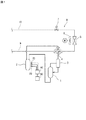
図1は、本発明の一実施形態に係る冷凍装置Rの冷媒回路図である。冷凍装置Rはビル用の空気調和装置の室外ユニット(室外機)からなり、主として、圧縮機1、アキュームレータ2、油分離器3、四路切換弁4、室外側熱交換器5、室外ファン6、及び膨張弁7を備えている。図1において、それぞれ参照符号9及び10で示されるガス管及び液管は、図示しない1又は複数の室内ユニットの冷媒配管に接続される。
FIG. 1 is a refrigerant circuit diagram of a refrigeration apparatus R according to an embodiment of the present invention. The refrigeration apparatus R is composed of an outdoor unit (outdoor unit) of an air conditioner for buildings, and mainly includes a
四路切換弁4は、冷房運転サイクルと暖房運転サイクルとを切り替えることができる。冷房運転時には、図1において実線で示される接続状態となり、圧縮機1から、油分離器3、室外側熱交換器5、室内側熱交換器(図示せず)及びアキュームレータ2を経て当該圧縮機1へと戻る冷房運転サイクルが構成される。一方、暖房運転時には、図1において破線で示される接続状態となり、圧縮機1から、油分離器3、室内側熱交換器(図示せず)、室外側熱交換器5及びアキュームレータ2を経て当該圧縮機1へと戻る暖房運転サイクルが構成される。
The four-
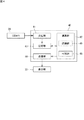
本実施形態に係る冷凍装置Rは、当該冷凍装置Rを構成する機器であるアキュームレータ2の内部に含まれる液冷媒の液面状態を判別する判別装置Dを備えている。判別装置Dは、図2に示されるように、液面計20と、CCDカメラ30と、制御部40と、表示部50とを備えている。
The refrigeration apparatus R according to the present embodiment includes a determination device D that determines the liquid level state of the liquid refrigerant contained in the
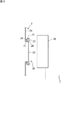
液面計20は、アキュームレータ2内の液冷媒の液面を確認する確認部を構成している。本実施形態における液面計20は、図3に示されるように、アキュームレータ2の壁面2aに形成された丸孔の周縁に立設された短円筒体21と、当該短円筒体21の先端周縁に設けられた鍔部22と、前記丸孔を閉止し得る大きさの円形の窓体23と、当該窓体23を前記鍔部22に固定する環状の固定部24とを備えている。窓体23は、アキュームレータ2内の液冷媒の液面を機外から観察することができるように、ガラス等の透明な材料で作製されている。固定部24は、例えばボルト25及びナット26を用いて鍔部22に固定することができる。
The
本実施形態では、アキュームレータ2の壁面2aに複数の液面計20、具体的には3つの液面計20が設けられている。3つの液面計20は、設置された状態のアキュームレータ2の上下方向(図2において上下方向)に沿って設けられており、上から順に上液面計20a、中液面計20b、及び下液面計20cを構成している。後述するように、本実施形態の判別装置Dは、液面計20の透明な窓体23の画像を用いてアキュームレータ2内の液冷媒の液面状態を判別しているが、1つの液面計20であると、窓体23を介して撮像されるアキュームレータ2内の領域が液冷媒で満たされているのか、又は、液冷媒が全く存在していないのか、画像からは判別が難しいこともある。しかし、複数の液面計20を設けることで、いずれかの液面計20の窓体23に液部分と非液部分との境界を位置させること、又は、内側が液冷媒で満たされた窓部と内側に液冷媒が存在しない窓部とを併存させることが可能となる。その結果、3つの液面計20から得られる3つの画像を総合的に判断することで、アキュームレータ2内の液冷媒の液面状態をより高精度に判別することができる。なお、液面計20の数は、3つに限定されるものではなく、2つであってもよいし、4つ以上であってもよい。また、比較的小容量の液冷媒が収容されるアキュームレータの場合は、1つの液面計でも内部の液面状態を精度よく観察できることもある。
In the present embodiment, a plurality of liquid level gauges 20, specifically, three liquid level gauges 20 are provided on the
CCDカメラ30は、窓体23を介してアキュームレータ2内の液冷媒の液面を撮像することができる撮像部を構成しており、図3に示されるように、液面計20の窓体23の正面前方に、当該窓体23との間に所定距離、例えば5cm程度の距離を隔てて配設されている。本実施形態では、3つの液面計20のそれぞれに対応して合計3台のCCDカメラ30が配設されている。CCDカメラ30によって液面計20の窓体23の部分を含む動画が撮像され、撮像された動画は制御部40に送信される。
The
制御部40はマイクロコンピュータ等からなっており、CCDカメラ30からの画像信号を受信する受信部41、演算部42、記憶部43、及び送信部44を備えている。演算部42は、演算処理の中枢として機能するCPUからなっており、機能的には、認識部45及び判別部46を備えている。演算部42による処理の結果は、送信部44から制御部40に接続されている表示部50に送信される。
The
記憶部43は、演算部42の制御プログラム(判別プログラムを含む)が格納されたROMと、当該演算部42が制御動作を行う際にデータ等が一時的に書き込まれたり、その書き込まれたデータが読みだされたりするRAMとから構成されている。本実施形態の判別プログラムは、アキュームレータ2の液面状態を判別するために制御部40を、アキュームレータ2内の液面を確認する液面計20で確認される液面を撮像するCCDカメラ30で撮像された液面画像を認識する認識部45、及び前記認識部45で認識した画像を予め設定された複数の分類のいずれかに分類する判別部46として機能させる。
The
表示部50は、例えば後述する判別結果を時系列で表示するための液晶表示素子、プラズマ表示素子又はCRT等で構成されている。
The
つぎに、前述した判別装置Dを用いてアキュームレータ2内の液冷媒の液面状態を判別する方法の一例について説明する。以下に例示する判別方法では、オペレータが目視により液面状態を判別するのではなく、CCDカメラ30を用いて撮像した画像データを自動分類し、アキュームレータ2内の液冷媒の液面レベルを数値化して出力している。
Next, an example of a method for determining the liquid level state of the liquid refrigerant in the
まずCCDカメラ30を用いてアキュームレータ2に設けられた液面計20の窓体23を含む領域が動画として撮像される。撮像された画像(動画)は、制御部40の受信部41に送信され、当該受信部41で受信された画像は制御部40の記憶部43に記憶される。
First, a region including the
ついで、演算部42によって、記憶部43に記憶されている画像(動画)が静止画に変換される。例えば、1枚/1秒の間隔ないし頻度で動画から静止画を取得することができる。
Next, the
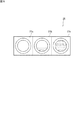
ついで、演算部42の認識部45によって、取得された静止画が認識され、この認識部45により認識された静止画は、演算部42の判別部46によって、予め設定された複数の分類のいずれかに分類される。本実施形態では、アキュームレータ2の3つの液面計20の液面の画像を取得している。このため、演算部42は、同時刻に得られる3つの画像、すなわち上液面計20aからの画像27a、中液面計20bからの画像27b、及び下液面計20cからの画像27cを、例えば図5に示されるような1つの画像28にまとめる処理を行う。認識部45は、この画像28を認識する。
Next, the acquired still image is recognized by the
前述した液面状態を示す画像(液面画像)である静止画の認識及び分類は、一般に入手可能な、例えばCaffe等の画像認識又は画像解析ソフトウェアを利用して行うことができ、制御部40の記憶部43には、予めこのような画像認識又は画像解析ソフトウェアが格納されている。
Recognition and classification of the still image which is the image (liquid level image) indicating the liquid level state described above can be performed by using generally available image recognition or image analysis software such as Caffe, and the
Caffe等の画像解析ソフトウェアを用いて画像の分類処理を行うに際し、予め液面画像に関する情報である学習画像情報(学習モデル)が生成され、生成された学習画像情報が学習画像格納部として機能する記憶部43に格納される。かかる学習画像情報は深層学習(Deep Learning)を用いて学習された情報であり、アキュームレータの液面状態の複数の分類は、当該学習画像情報によって生成される。
When image classification processing is performed using image analysis software such as Caffe, learning image information (learning model) that is information relating to the liquid level image is generated in advance, and the generated learning image information functions as a learning image storage unit. It is stored in the
本実施形態で用いられる、液面画像に関する情報である学習画像情報は、例えば、以下のようにして生成することができる。
まず、液面状態を判別しようとするアキュームレータと同じ仕様のアキュームレータについて、過去の録画画像より様々な液面状態の画像を教師画像として収集する。本実施形態では、3つの液面計を備えたアキュームレータの液面状態を判別するので、同じく3つの液面計を備えたアキュームレータについて様々な液面状態の画像を収集し、図5に示されるように3つの画像を1つにまとめた画像を画像解析ソフトウェアに投入する。その際、収集した画像(3つの画像が1つのまとまったもの)のそれぞれについて、オペレータの目視による判断で分類値を与え、当該分類値と画像とをリンクさせて画像解析ソフトウェアに投入する。図6は、3つの液面計を備えたアキュームレータ内の冷媒の複数のレベルの液面状態を示す表の一例である。例示した表では、液面状態が12のケースに分類されている。なお、分類自体は、12未満のケースに分類してもよいし、12を超えるケースに分類してもよい。
The learning image information that is information related to the liquid level image used in the present embodiment can be generated as follows, for example.
First, for an accumulator having the same specifications as the accumulator for which the liquid level state is to be determined, images of various liquid level states are collected as a teacher image from past recorded images. In the present embodiment, since the liquid level state of the accumulator provided with three liquid level gauges is determined, images of various liquid level states are collected for the accumulator similarly provided with three liquid level gauges, as shown in FIG. In this way, an image obtained by combining three images into one image is input to the image analysis software. At that time, for each of the collected images (a group of three images), a classification value is given by visual judgment of the operator, and the classification value and the image are linked and input to image analysis software. FIG. 6 is an example of a table showing liquid level states at a plurality of levels of refrigerant in an accumulator equipped with three liquid level gauges. In the illustrated table, the liquid surface state is classified into 12 cases. The classification itself may be classified into less than 12 cases or more than 12 cases.
図6に示される例では、各液面計について4つの液面状態に分類し、全体として合計12のケースに分類している。分類「1」が最も液量が少ない状態であり、上液面計20a及び中液面計20bの液面レベルが0%、すなわち液冷媒が観察されない状態であり、下液面計20cの液面レベルは0%〜24%の範囲内である。また、分類「12」が最も液量が多い状態であり、中液面計20b及び下液面計20cの液面レベルが100%、すなわち中液面計20b及び下液面計20cで観察される範囲では満液状態であり、上液面計20aの液面レベルは75%〜100%の範囲内である。通常、分類が「12」以上であるとオーバーフローが発生する可能性が考えられる。
In the example shown in FIG. 6, each liquid level gauge is classified into four liquid level states, and the total is classified into 12 cases. The classification “1” is the state where the liquid level is the smallest, the liquid level of the upper
演算部42によって1つのまとめられた画像28を、前述した学習画像情報に投入すると投入された画像28の特徴が捉えられて、1〜12のいずれかの分類値が出力される。このようにして、本実施形態では、アキュームレータ2内の液面レベルを機械的に且つ自動的に1〜12のいずれかの分類値に変換して出力することができる。
図7は、液面画像の判別結果である液面レベルの時系列での表示例を示している。図7に示される例では、所定間隔で連続して取得された100の画像について、液面レベルが1〜20のいずれかの分類値に変換して出力されている。
When one
FIG. 7 shows a time-series display example of the liquid level, which is the determination result of the liquid level image. In the example shown in FIG. 7, the liquid level is converted into one of 1 to 20 classification values and output for 100 images obtained continuously at predetermined intervals.
本実施形態に係る冷凍装置Rにおいて、前記判別装置Dの判別部46による判別結果が所定の警戒範囲にあるときに当該冷凍装置Rの保護制御を行うようにすることもできる。この場合、冷凍装置Rの保護制御を行うことで、圧縮機1の油切れやアキュームレータ2のオーバーフローによって圧縮機1に焼き付き等の不具合が生じるのを防止して、当該冷凍装置Rの信頼性を向上させることができる。
In the refrigeration apparatus R according to the present embodiment, protection control of the refrigeration apparatus R can be performed when the determination result by the
冷凍装置Rの警戒範囲としては、例えば圧縮機1については所定の液面以下とし、アキュームレータ2については所定の液面以上とすることができる。また、保護制御としては、機器の異常の通知、機器の運転の停止、及び圧縮機1への油戻し運転のいずれかとすることができる。判別部46による判別結果が所定の警戒範囲にあるときに、機器の異常の通知、機器の運転の停止、及び圧縮機1への油戻し運転のいずれかを行うことで、冷凍装置Rの圧縮機1に焼き付き等の不具合が生じるのを防止することができる。
As a warning range of the refrigeration apparatus R, for example, the
〔その他の変形例〕
本発明は前述した実施形態に限定されるものではなく、特許請求の範囲内において種々の変更が可能である。
例えば、前述した実施形態では撮像部を構成するCCDカメラで動画を撮像し、この動画を静止画に変換しているが、CCDカメラで所定時間毎に静止画を撮像し、得られる静止画を用いて液面状態を判別することもできる。
[Other variations]
The present invention is not limited to the above-described embodiments, and various modifications can be made within the scope of the claims.
For example, in the above-described embodiment, a moving image is picked up by a CCD camera that constitutes an image pickup unit, and the moving image is converted into a still image. It can also be used to determine the liquid level.
また、前述した実施形態では、撮像部としてCCDカメラを用いているが、アキュームレータ等の機器における液面を撮像することができる撮像部としては、CCDカメラ以外にも、例えばCMOSカメラ等のデジタルカメラを用いることができる。 In the above-described embodiment, a CCD camera is used as the imaging unit. However, as an imaging unit capable of imaging the liquid level in an accumulator or the like, a digital camera such as a CMOS camera can be used in addition to the CCD camera. Can be used.
また、前述した実施形態では、液面計の正面前方に撮像部としてのCCDカメラを配置しているが、液面計を介してアキュームレータ内の液冷媒の液面が撮像できる範囲内であれば、CCDカメラの位置は適宜変更することができる。
また、前述した実施形態では、冷凍装置のアキュームレータ内の液冷媒の液面状態を判別しているが、本発明の判別装置は、同じく冷凍装置を構成する圧縮機内の冷凍機油の液面状態を判別することもできる。
In the above-described embodiment, a CCD camera as an imaging unit is arranged in front of the liquid level gauge. However, as long as the liquid level of the liquid refrigerant in the accumulator can be imaged via the liquid level gauge. The position of the CCD camera can be changed as appropriate.
In the above-described embodiment, the liquid level state of the liquid refrigerant in the accumulator of the refrigeration apparatus is determined. However, the determination apparatus of the present invention also determines the liquid level state of the refrigeration oil in the compressor that constitutes the refrigeration apparatus. It can also be determined.
また、前述した実施形態に係る装置では、冷凍装置を構成する機器における液面状態を判別しているが、本発明は、冷凍装置を構成する機器における液状態を判別する装置にも適用することができる。
すなわち、本発明の他の実施形態に係る液状態判別装置は、冷凍装置を構成し内部に液が含まれる機器における液状態を判別する装置であって、
機器内の液状態を確認する確認部と、
前記確認部で確認される液状態を撮像する撮像部と、
前記撮像部で撮像された液状態画像を認識する認識部、及び前記認識部で認識した画像を予め設定された複数の分類のいずれかに分類する判別部を含む演算部と
を備えている。
液状態の例としては、例えば冷凍装置を構成する機器内の冷媒の汚れを挙げることができる。かかる冷媒の汚れを、前記撮像部および演算部によって複数の分類のいずれかに分類することで、検知または検出することができる。
Moreover, in the apparatus according to the above-described embodiment, the liquid level state in the equipment configuring the refrigeration apparatus is determined. However, the present invention is also applicable to an apparatus that determines the liquid state in the apparatus configuring the refrigeration apparatus. Can do.
That is, a liquid state determination apparatus according to another embodiment of the present invention is an apparatus that determines a liquid state in a device that constitutes a refrigeration apparatus and contains liquid therein,
A confirmation unit for confirming the liquid state in the device;
An imaging unit for imaging the liquid state confirmed by the confirmation unit;
A recognition unit that recognizes a liquid state image captured by the imaging unit, and a calculation unit that includes a determination unit that classifies the image recognized by the recognition unit into one of a plurality of preset classifications.
As an example of a liquid state, the dirt of the refrigerant | coolant in the apparatus which comprises a freezing apparatus can be mentioned, for example. Such contamination of the refrigerant can be detected or detected by classifying the refrigerant into any one of a plurality of classifications by the imaging unit and the calculation unit.
1 :圧縮機
2 :アキュームレータ
2a:壁面
3 :油分離器
4 :四路切換弁
5 :室外側熱交換器
6 :室外ファン
7 :膨張弁
9 :ガス管
10 :液管
20 :液面計
20a:上液面計
20b:中液面計
20c:下液面計
21 :短筒体
22 :鍔部
23 :窓体
24 :固定部
25 :ボルト
26 :ナット
27a:画像
27b:画像
27c:画像
28 :画像
30 :CCDカメラ
40 :制御部
41 :受信部
42 :演算部
43 :記憶部
44 :送信部
45 :認識部
46 :判別部
50 :表示部
D :冷凍装置
R :判別装置
DESCRIPTION OF SYMBOLS 1: Compressor 2:
Claims (12)
機器内の液面を確認する確認部(20)と、
前記確認部(20)で確認される液面を撮像する撮像部(30)と、
前記撮像部(30)で撮像された液面画像を認識する認識部(45)、及び前記認識部(45)で認識した画像を予め設定された3以上の複数の分類のいずれかに分類する判別部(46)を含む演算部(42)と
を備えている、液面状態判別装置(D)。 An apparatus for determining a liquid surface state in a device that constitutes a refrigeration apparatus (R) and contains liquid therein,
A confirmation unit (20) for confirming the liquid level in the device;
An imaging unit (30) for imaging the liquid level confirmed by the confirmation unit (20);
The recognition unit (45) for recognizing the liquid level image captured by the imaging unit (30), and the image recognized by the recognition unit (45) are classified into any of a plurality of preset three or more classifications. A liquid level state discriminating device (D) comprising a calculating unit (42) including a discriminating unit (46).
機器内の液面を確認する確認部(20)と、
前記確認部(20)で確認される液面を撮像する撮像部(30)と、
前記撮像部(30)で撮像された液面画像を認識する認識部(45)、及び前記認識部(45)で認識した画像を予め設定された複数の分類のいずれかに分類する判別部(46)を含む演算部(42)と
を備えており、
前記判別する装置は、複数の確認部(20)、及び当該確認部(20)の数に対応した複数の撮像部(30)を備えており、
前記演算部(42)は、得られる複数の画像を一つの画像として前記認識部(45)に認識させる、液面状態判別装置(D)。 An apparatus for determining a liquid surface state in a device that constitutes a refrigeration apparatus (R) and contains liquid therein,
A confirmation unit (20) for confirming the liquid level in the device;
An imaging unit (30) for imaging the liquid level confirmed by the confirmation unit (20);
A recognition unit (45) that recognizes the liquid level image captured by the imaging unit (30), and a determination unit that classifies the image recognized by the recognition unit (45) into one of a plurality of preset categories. 46) including a calculation unit (42),
The apparatus for determining includes a plurality of confirmation units (20) and a plurality of imaging units (30) corresponding to the number of the confirmation units (20).
The said calculating part (42) is a liquid level state determination apparatus (D) which makes the said recognition part (45) recognize the several image obtained as one image.
前記複数の分類は前記学習画像情報により作成されるものであり、
前記学習画像情報は深層学習を用いて学習された情報である、請求項1又は請求項2に記載の液面状態判別装置(D)。 A learning image storage unit (43) that stores learning image information that is information about the liquid level image;
The plurality of classifications are created by the learning image information,
The liquid level state discriminating device (D) according to claim 1 or 2, wherein the learning image information is information learned by using deep learning.
機器内の液状態を確認する確認部(20)と、
前記確認部(20)で確認される液状態を撮像する撮像部(30)と、
前記撮像部(30)で撮像された液状態画像を認識する認識部(45)、及び前記認識部(45)で認識した画像を予め設定された3以上の複数の分類のいずれかに分類する判別部(46)を含む演算部(42)と
を備えている、液状態判別装置(D)。 An apparatus for determining a liquid state in a device that constitutes a refrigeration apparatus (R) and contains liquid therein,
A confirmation unit (20) for confirming the liquid state in the device;
An imaging unit (30) for imaging the liquid state confirmed by the confirmation unit (20);
The recognition unit (45) for recognizing the liquid state image captured by the imaging unit (30), and the image recognized by the recognition unit (45) are classified into any of a plurality of preset three or more classifications. A liquid state discriminating device (D) comprising an arithmetic unit (42) including a discriminating unit (46).
機器内の液状態を確認する確認部(20)と、
前記確認部(20)で確認される液状態を撮像する撮像部(30)と、
前記撮像部(30)で撮像された液状態画像を認識する認識部(45)、及び前記認識部(45)で認識した画像を予め設定された複数の分類のいずれかに分類する判別部(46)を含む演算部(42)と
を備えており、
前記判別する装置は、複数の確認部(20)、及び当該確認部(20)の数に対応した複数の撮像部(30)を備えており、
前記演算部(42)は、得られる複数の画像を一つの画像として前記認識部(45)に認識させる、液状態判別装置(D)。
An apparatus for determining a liquid state in a device that constitutes a refrigeration apparatus (R) and contains liquid therein,
A confirmation unit (20) for confirming the liquid state in the device;
An imaging unit (30) for imaging the liquid state confirmed by the confirmation unit (20);
A recognition unit (45) that recognizes the liquid state image captured by the imaging unit (30), and a determination unit that classifies the image recognized by the recognition unit (45) into one of a plurality of preset categories. 46) including a calculation unit (42),
The apparatus for determining includes a plurality of confirmation units (20) and a plurality of imaging units (30) corresponding to the number of the confirmation units (20).
The said calculating part (42) is a liquid state determination apparatus (D) which makes the said recognition part (45) recognize the some image obtained as one image.
Priority Applications (1)
| Application Number | Priority Date | Filing Date | Title |
|---|---|---|---|
| JP2019102027A JP2019190820A (en) | 2019-05-31 | 2019-05-31 | Liquid surface state determination device, freezing device including the same and liquid surface state determination program |
Applications Claiming Priority (1)
| Application Number | Priority Date | Filing Date | Title |
|---|---|---|---|
| JP2019102027A JP2019190820A (en) | 2019-05-31 | 2019-05-31 | Liquid surface state determination device, freezing device including the same and liquid surface state determination program |
Related Parent Applications (1)
| Application Number | Title | Priority Date | Filing Date |
|---|---|---|---|
| JP2016253751A Division JP6565897B2 (en) | 2016-12-27 | 2016-12-27 | Liquid level state discriminating apparatus, refrigeration apparatus equipped with the same, and liquid level state discriminating program |
Publications (1)
| Publication Number | Publication Date |
|---|---|
| JP2019190820A true JP2019190820A (en) | 2019-10-31 |
Family
ID=68389575
Family Applications (1)
| Application Number | Title | Priority Date | Filing Date |
|---|---|---|---|
| JP2019102027A Pending JP2019190820A (en) | 2019-05-31 | 2019-05-31 | Liquid surface state determination device, freezing device including the same and liquid surface state determination program |
Country Status (1)
| Country | Link |
|---|---|
| JP (1) | JP2019190820A (en) |
Cited By (3)
| Publication number | Priority date | Publication date | Assignee | Title |
|---|---|---|---|---|
| KR20220097743A (en) * | 2020-12-31 | 2022-07-08 | 동국대학교 산학협력단 | System of detecting defective gas-lighters using computer vision library |
| JP2022119247A (en) * | 2021-02-04 | 2022-08-17 | パナソニックIpマネジメント株式会社 | Monitoring system |
| WO2025022950A1 (en) * | 2023-07-26 | 2025-01-30 | コベルコ・コンプレッサ株式会社 | Packaged compressor |
Citations (11)
| Publication number | Priority date | Publication date | Assignee | Title |
|---|---|---|---|---|
| JPS5733769A (en) * | 1980-08-07 | 1982-02-23 | Nissan Motor | Refrigerating plant for automobiles |
| JPH0989422A (en) * | 1995-09-21 | 1997-04-04 | Hitachi Bill Shisetsu Eng Kk | Method and apparatus for monitoring leakage of liquid enclosed in closed circulation system |
| JP2004125309A (en) * | 2002-10-03 | 2004-04-22 | Mitsubishi Electric Corp | Oil changer for refrigeration cycle |
| JP2005037281A (en) * | 2003-07-16 | 2005-02-10 | Nec Plasma Display Corp | Display device manufacturing method, display device substrate inspection method, and display device substrate inspection device |
| JP2007135349A (en) * | 2005-11-11 | 2007-05-31 | Kansai Electric Power Co Inc:The | Deterioration diagnosing method for power transmission facility |
| JP2012206132A (en) * | 2011-03-29 | 2012-10-25 | Kobe Steel Ltd | Rolling method and rolling machine |
| JP2013139902A (en) * | 2011-12-28 | 2013-07-18 | Daikin Industries Ltd | Refrigeration device |
| JP2014202469A (en) * | 2013-04-10 | 2014-10-27 | 株式会社Ihi | Heat pump unit and operation method of heat pump unit |
| JP5969685B1 (en) * | 2015-12-15 | 2016-08-17 | ウエノテックス株式会社 | Waste sorting system and sorting method |
| JP2016198197A (en) * | 2015-04-08 | 2016-12-01 | 株式会社エクスメディオ | Diagnosis support system and application program |
| JP2016211955A (en) * | 2015-05-08 | 2016-12-15 | 古河電気工業株式会社 | Bridge inspection support device, bridge inspection support method, bridge inspection support system, and program |
-
2019
- 2019-05-31 JP JP2019102027A patent/JP2019190820A/en active Pending
Patent Citations (11)
| Publication number | Priority date | Publication date | Assignee | Title |
|---|---|---|---|---|
| JPS5733769A (en) * | 1980-08-07 | 1982-02-23 | Nissan Motor | Refrigerating plant for automobiles |
| JPH0989422A (en) * | 1995-09-21 | 1997-04-04 | Hitachi Bill Shisetsu Eng Kk | Method and apparatus for monitoring leakage of liquid enclosed in closed circulation system |
| JP2004125309A (en) * | 2002-10-03 | 2004-04-22 | Mitsubishi Electric Corp | Oil changer for refrigeration cycle |
| JP2005037281A (en) * | 2003-07-16 | 2005-02-10 | Nec Plasma Display Corp | Display device manufacturing method, display device substrate inspection method, and display device substrate inspection device |
| JP2007135349A (en) * | 2005-11-11 | 2007-05-31 | Kansai Electric Power Co Inc:The | Deterioration diagnosing method for power transmission facility |
| JP2012206132A (en) * | 2011-03-29 | 2012-10-25 | Kobe Steel Ltd | Rolling method and rolling machine |
| JP2013139902A (en) * | 2011-12-28 | 2013-07-18 | Daikin Industries Ltd | Refrigeration device |
| JP2014202469A (en) * | 2013-04-10 | 2014-10-27 | 株式会社Ihi | Heat pump unit and operation method of heat pump unit |
| JP2016198197A (en) * | 2015-04-08 | 2016-12-01 | 株式会社エクスメディオ | Diagnosis support system and application program |
| JP2016211955A (en) * | 2015-05-08 | 2016-12-15 | 古河電気工業株式会社 | Bridge inspection support device, bridge inspection support method, bridge inspection support system, and program |
| JP5969685B1 (en) * | 2015-12-15 | 2016-08-17 | ウエノテックス株式会社 | Waste sorting system and sorting method |
Cited By (4)
| Publication number | Priority date | Publication date | Assignee | Title |
|---|---|---|---|---|
| KR20220097743A (en) * | 2020-12-31 | 2022-07-08 | 동국대학교 산학협력단 | System of detecting defective gas-lighters using computer vision library |
| KR102523809B1 (en) | 2020-12-31 | 2023-04-20 | 동국대학교 산학협력단 | System of detecting defective gas-lighters using computer vision library |
| JP2022119247A (en) * | 2021-02-04 | 2022-08-17 | パナソニックIpマネジメント株式会社 | Monitoring system |
| WO2025022950A1 (en) * | 2023-07-26 | 2025-01-30 | コベルコ・コンプレッサ株式会社 | Packaged compressor |
Similar Documents
| Publication | Publication Date | Title |
|---|---|---|
| Guan et al. | Automatic fault diagnosis algorithm for hot water pipes based on infrared thermal images | |
| JP2019190820A (en) | Liquid surface state determination device, freezing device including the same and liquid surface state determination program | |
| CN103459728A (en) | Excavator and its monitoring device and output device of the excavator | |
| CN105973168A (en) | Operation diagnosis system and method for gas chamber piston | |
| CN111931827B (en) | Hydraulic pump health detection system based on multi-sensor information fusion | |
| US20240019151A1 (en) | Unmanned inspection system and method of HVAC room based on artificial intelligence | |
| CN113758932A (en) | A Deep Learning-Based Vision System for Lithium Battery Diaphragm Defects | |
| CN109506625A (en) | Landslide dangerous situation monitoring method, system and its image data acquisition device | |
| JPH0765152A (en) | Device and method for monitoring | |
| KR100743801B1 (en) | Diagnostic system for gel dispensing condition and method thereof | |
| CN110307617B (en) | Heat exchanger, filth blockage detection method, device and system thereof, and electrical equipment | |
| CN111283013A (en) | Machine vision-based ball head detection system and detection method for pipe benders | |
| CN104142176A (en) | Vibration detection device of air conditioner | |
| JP6565897B2 (en) | Liquid level state discriminating apparatus, refrigeration apparatus equipped with the same, and liquid level state discriminating program | |
| CN111914589B (en) | Monitoring methods, computing equipment, devices, monitoring systems, and computer-readable storage media for the installation process of air conditioning units | |
| CN110989604A (en) | Method and equipment for processing data by using robot and robot | |
| CN118730600B (en) | A method and device for detecting abnormality of thermal imaging of uncooled infrared detector | |
| CN120183195A (en) | A charging parking space status detection system and method based on multimodal perception | |
| CN119323763A (en) | Anomaly monitoring method and device for target object, computer equipment and storage medium | |
| CN112810399A (en) | Parking air conditioner and method for detecting cleanliness | |
| CN113696794B (en) | A cooling system for fuel cell cooling for new energy vehicles | |
| CN205784880U (en) | Shoot scoring round target device in real time | |
| JPH07209035A (en) | Equipment condition monitoring device | |
| JP2009265998A (en) | Image processing system, image processing method, and image processing program | |
| TWM625907U (en) | Radar wave water level indicator |
Legal Events
| Date | Code | Title | Description |
|---|---|---|---|
| A521 | Request for written amendment filed |
Free format text: JAPANESE INTERMEDIATE CODE: A523 Effective date: 20190531 |
|
| A621 | Written request for application examination |
Free format text: JAPANESE INTERMEDIATE CODE: A621 Effective date: 20191028 |
|
| A131 | Notification of reasons for refusal |
Free format text: JAPANESE INTERMEDIATE CODE: A131 Effective date: 20200825 |
|
| A521 | Request for written amendment filed |
Free format text: JAPANESE INTERMEDIATE CODE: A523 Effective date: 20201022 |
|
| A02 | Decision of refusal |
Free format text: JAPANESE INTERMEDIATE CODE: A02 Effective date: 20201124 |