JP2019190836A - Magnetic anisotropy evaluation apparatus, magnetic anisotropy evaluation method, and calculation mechanism - Google Patents
Magnetic anisotropy evaluation apparatus, magnetic anisotropy evaluation method, and calculation mechanism Download PDFInfo
- Publication number
- JP2019190836A JP2019190836A JP2018079748A JP2018079748A JP2019190836A JP 2019190836 A JP2019190836 A JP 2019190836A JP 2018079748 A JP2018079748 A JP 2018079748A JP 2018079748 A JP2018079748 A JP 2018079748A JP 2019190836 A JP2019190836 A JP 2019190836A
- Authority
- JP
- Japan
- Prior art keywords
- magnetic
- magnetic field
- hall resistance
- angle
- hall
- Prior art date
- Legal status (The legal status is an assumption and is not a legal conclusion. Google has not performed a legal analysis and makes no representation as to the accuracy of the status listed.)
- Granted
Links
Images


Landscapes
- Measuring Magnetic Variables (AREA)
- Investigating Or Analyzing Materials By The Use Of Magnetic Means (AREA)
- Manufacturing Of Magnetic Record Carriers (AREA)
Abstract
【課題】磁性薄膜における磁気異方性評価を正確に行う手段を提供する。【解決手段】本発明の磁気異方性評価方法は、平坦な平面を有する薄膜の磁性体のホール抵抗を測定するステップと、前記磁性体に磁界を印加するステップと、前記磁性体のホール抵抗の印加磁界角度依存性から、磁気トルク曲線を演算するステップ、及び前記演算した磁気トルク曲線から磁気異方性定数を演算するするステップと、を備えたことを特徴とする。【選択図】図3PROBLEM TO BE SOLVED: To provide a means for accurately evaluating magnetic anisotropy in a magnetic thin film. A magnetic anisotropy evaluation method of the present invention includes a step of measuring a hole resistance of a magnetic material of a thin film having a flat plane, a step of applying a magnetic field to the magnetic material, and a hole resistance of the magnetic material. And a step of calculating a magnetic torque curve based on the applied magnetic field angle dependency of the above, and a step of calculating a magnetic anisotropy constant from the calculated magnetic torque curve. [Selection diagram] Fig. 3
Description
本発明は、磁性体の磁気異方性評価装置および磁気異方性評価方法に関し、詳しくは、トルク曲線を用いて磁気異方性を評価する技術に関する。 The present invention relates to a magnetic anisotropy evaluation apparatus and a magnetic anisotropy evaluation method for a magnetic material, and more particularly to a technique for evaluating magnetic anisotropy using a torque curve.
磁性体の磁気異方性は、例えば、磁気記録媒体において知られる特性である。すなわち、磁気記録媒体において磁気記録の高密度化を図るべく、磁気記録層中の磁性結晶粒の粒径を縮小させる。そして、磁性結晶粒の粒径の縮小は、記録された磁化(信号)の熱安定性を低下させる。そのため、磁性結晶粒の粒径の縮小による熱安定性の低下を補償するために、磁性結晶粒を、より高い磁気異方性を有する材料を用いて形成する。その結果、磁気記録媒体の磁気記録層が磁気異方性を持つことになる。 The magnetic anisotropy of the magnetic material is a characteristic known in, for example, a magnetic recording medium. That is, in order to increase the density of magnetic recording in the magnetic recording medium, the grain size of the magnetic crystal grains in the magnetic recording layer is reduced. And the reduction of the grain size of the magnetic crystal grains reduces the thermal stability of the recorded magnetization (signal). Therefore, the magnetic crystal grains are formed using a material having higher magnetic anisotropy in order to compensate for a decrease in thermal stability due to the reduction in the grain diameter of the magnetic crystal grains. As a result, the magnetic recording layer of the magnetic recording medium has magnetic anisotropy.
比較的大きな磁気異方性を有する材料として、L10型規則合金が提案されている。特許文献1は、Fe、CoおよびNiからなる群から選択される少なくとも1種の元素と、Pt、Pd、AuおよびIrからなる群から選択される少なくとも1種の元素とを含むL10型規則合金を記載している。代表的なL10型規則合金は、FePt、CoPt、FePd、CoPdなどを含む。
As a material having a relatively large magnetic anisotropy, L1 0 type ordered alloys have been proposed.
さらに、特許文献1には、磁気記録層を高密度化するための一方式として、磁性結晶粒の周囲を酸化物や窒化物のような非磁性結晶粒界で囲んだグラニュラー構造を用いる方法が提案されている。
Further, in
特許文献2には、合金の結晶粒の間に非磁性物質を介在させて磁性薄膜(磁性体の薄膜)をグラニュラー膜とした構成が記載されている。このグラニュラー膜を形成するために用いられる非磁性物質として、SiO2、Cr2O3、ZrO2、及びAl2O3などが挙げられている。これらの非磁性物質は、Co−Pt−C系合金の結晶粒を磁気的に分離する可能性が高い。
特許文献3には、グラニュラー構造を備えた磁性薄膜が記載されている。このグラニュラー構造は、L11型の原子の規則構造を有するCo−M−Pt合金(前記Mは単一若しくは複数のCo,Pt以外の金属元素を示す。)を主成分とする強磁性結晶粒と、この強磁性結晶粒を取り囲む非磁性粒界とからなる。前記合金は、グラニュラー構造を持つCoFePt等の3元系規則合金である。
従来、以上のような、磁性体の磁気異方性の評価は、磁気トルク曲線を直接測定することによって行われていた。具体的には、例えば下記式(1)に示すような、求めた磁気トルク(曲線)Tから記述要素としての磁気異方性エネルギーの成分を求め、これら成分に基づいて磁気異方性定数を求める。そして、この定数によって磁気異方性の評価を行う。磁気トルク曲線を測定する方法は、例えば、非特許文献1に記載されている。この方法は、磁性薄膜に磁界を印加した際に発生する磁気トルクを力学的に測定するものである。
Conventionally, the evaluation of magnetic anisotropy of a magnetic material as described above has been performed by directly measuring a magnetic torque curve. Specifically, for example, a component of magnetic anisotropy energy as a description element is obtained from the obtained magnetic torque (curve) T as shown in the following formula (1), and the magnetic anisotropy constant is calculated based on these components. Ask. Then, the magnetic anisotropy is evaluated by this constant. A method for measuring a magnetic torque curve is described in
T=−(Ku1+Ku2)sin2θM+(Ku2/2)sin4θM 式(1)
ここで、
Ku1:磁気異方性エネルギーの第1成分(第1次成分)
Ku2:磁気異方性エネルギーの第2成分(第2次成分)
θM:磁化容易軸と磁化のなす角
なお、磁気トルクとは、試料に磁界を印加して試料が磁化した時に、その内部磁化が磁界方向に向く。つまり、磁化容易方向が磁界の方向に向こうとして、試料に働く回転力である。また、磁気トルク曲線とは磁界方向(磁界角度)と磁気トルクの関係である。
T = − (K u1 + K u2 ) sin 2θ M + (K u2 / 2) sin 4θ M formula (1)
here,
K u1 : first component of magnetic anisotropy energy (primary component)
K u2 : second component of magnetic anisotropy energy (secondary component)
θ M : Angle between easy axis and magnetization Note that magnetic torque means that when a magnetic field is applied to a sample and the sample is magnetized, its internal magnetization is directed in the direction of the magnetic field. That is, it is a rotational force that acts on the sample when the easy magnetization direction is in the direction of the magnetic field. The magnetic torque curve is the relationship between the magnetic field direction (magnetic field angle) and the magnetic torque.
しかし、上述の磁気トルクを測定する方法では、試料基板や測定ホルダからの反磁界の影響や測定ノイズの影響があり、磁気トルクを精度よく測定することが困難であった。結果として、磁気異方性の評価に大きな誤差を生じる場合があった。 However, in the method of measuring the magnetic torque described above, there is an influence of a demagnetizing field from the sample substrate and the measurement holder and an influence of measurement noise, and it is difficult to accurately measure the magnetic torque. As a result, a large error may occur in the evaluation of magnetic anisotropy.
本発明は上述の問題に鑑みなされたものであって、その目的とするところは、磁性薄膜における磁気異方性評価を正確に行うことを可能とする磁気異方性評価装置および磁気異方性評価方法提供することである。 The present invention has been made in view of the above-described problems, and the object of the present invention is to provide a magnetic anisotropy evaluation apparatus and a magnetic anisotropy that enable accurate magnetic anisotropy evaluation in a magnetic thin film. It is to provide an evaluation method.
本発明の課題を解決するための手段の一例は、平坦な平面を有する薄膜の磁性体のホール抵抗を測定する機構と、前記磁性体に磁界を印加する機構と、前記磁性体のホール抵抗の印加磁界角度依存性から、磁気トルク曲線を演算する第1の演算と、前記演算した磁気トルク曲線から磁気異方性定数を演算するための第2の演算する機構と、を備えたことを特徴とする磁気異方性評価装置である。 An example of means for solving the problems of the present invention includes a mechanism for measuring the Hall resistance of a thin magnetic body having a flat plane, a mechanism for applying a magnetic field to the magnetic body, and the Hall resistance of the magnetic body. A first calculation for calculating a magnetic torque curve based on the applied magnetic field angle dependency, and a second calculation mechanism for calculating a magnetic anisotropy constant from the calculated magnetic torque curve are provided. Is a magnetic anisotropy evaluation apparatus.
本発明の課題を解決するための手段の別の一例は、前記磁気異方性評価装置の磁界印加機構から印加される磁界をホールセンサで読み取り、印加磁界強度と読み取り磁界強度の比較から磁界方向を測定する前記角度測定機構を備えた磁気異方性評価装置、および、前記磁気異方性評価装置を用いて正常ホール抵抗および磁気抵抗の印加磁界角度依存性を導出し、正常ホール抵抗および磁気抵抗の印加磁界角度依存性を用いて、磁性体のホール抵抗の測定結果から正常ホール抵抗成分と磁気抵抗成分を分離し、磁性体の異常ホール抵抗成分の印加磁界角度依存性を導出し、異常ホール抵抗成分の印加磁界角度依存性を用いて磁性体の磁気異方性を評価する磁気異方性評価方法である。 Another example of means for solving the problems of the present invention is that the magnetic field applied from the magnetic field application mechanism of the magnetic anisotropy evaluation apparatus is read by a Hall sensor, and the magnetic field direction is determined by comparing the applied magnetic field strength with the read magnetic field strength. The magnetic anisotropy evaluation apparatus provided with the angle measurement mechanism for measuring the magnetic anisotropy, and the applied magnetic field angle dependence of the normal Hall resistance and the magnetic resistance using the magnetic anisotropy evaluation apparatus are derived. Using the dependence of the magnetic field on the applied magnetic field angle, the normal Hall resistance component and the magnetoresistive component are separated from the measurement result of the Hall resistance of the magnetic material, and the applied magnetic field angle dependency of the abnormal Hall resistance component of the magnetic material is derived. This is a magnetic anisotropy evaluation method for evaluating the magnetic anisotropy of a magnetic body using the applied magnetic field angle dependency of the Hall resistance component.
磁気異方性の解析手段の一例は、前記磁気トルク曲線から前記磁気異方性定数を演算する工程において、前記磁性体の磁気異方性を評価する手段として、前記磁気トルク曲線によるフィッティングを用いる磁気異方性評価方法である。 An example of magnetic anisotropy analysis means uses fitting by the magnetic torque curve as means for evaluating the magnetic anisotropy of the magnetic material in the step of calculating the magnetic anisotropy constant from the magnetic torque curve. It is a magnetic anisotropy evaluation method.
上記の磁気異方性評価装置および磁気異方性評価方法を採用することによって、試料基板や測定ホルダからの反磁界の影響や測定ノイズを低減することができるため、従来の方法では評価が困難な磁性体の磁気異方性を正確に評価することが可能になる。 By adopting the above magnetic anisotropy evaluation apparatus and magnetic anisotropy evaluation method, the influence of the demagnetizing field from the sample substrate and the measurement holder and measurement noise can be reduced. It is possible to accurately evaluate the magnetic anisotropy of a simple magnetic material.
以下、本発明の磁気異方性評価装置及び磁気異方性評価方法の形態について、図を用いて詳細に説明する。但し、本発明は以下に示す実施形態の記載内容に限定されず、本明細書等において開示する発明の趣旨から逸脱することなく形態および詳細を様々に変更し得ることは当業者にとって自明である。また、異なる実施の形態及び実施例に係る構成は、適宜組み合わせて実施することが可能である。 Hereinafter, embodiments of the magnetic anisotropy evaluation apparatus and the magnetic anisotropy evaluation method of the present invention will be described in detail with reference to the drawings. However, the present invention is not limited to the description of the embodiments described below, and it is obvious to those skilled in the art that various changes in form and details can be made without departing from the spirit of the invention disclosed in this specification and the like. . In addition, configurations according to different embodiments and examples can be implemented in appropriate combination.
本発明の一実施形態に係る磁気異方性評価装置は、磁気トルクを力学的に測定するのではなく、ホール効果による電気抵抗、すなわち、ホール抵抗を測定することによって求めるものである。すなわち、磁気トルクTは、磁化容易軸と磁化方向のなす角で記述される下記式(2)によっても表すことができ、この式(2)の、磁化角θMを、ホール抵抗を測定することによって求め、最終的に磁気トルク(曲線)を求める。磁化容易軸と磁化方向のなす角を、以下、「磁化角度」ないし「磁化角」ともいう。より具体的には、式(2)において、試料3のホール抵抗の磁界角度依存性及び磁界強度依存性を測定することによって、磁界角度θHに対する磁化角θMの関係を求め、最終的に磁気トルク曲線を求める。なお、磁界角度依存性は、印加磁界角度依存性と、また、磁界強度依存性は、印加磁界強度依存性と呼ぶことができる。
The magnetic anisotropy evaluation apparatus according to an embodiment of the present invention is obtained by measuring the electrical resistance due to the Hall effect, that is, the Hall resistance, instead of measuring the magnetic torque dynamically. That is, the magnetic torque T can also be expressed by the following equation (2) described by the angle formed by the easy axis and the magnetization direction. The magnetization angle θ M of this equation (2) is measured for the Hall resistance. The magnetic torque (curve) is finally obtained. Hereinafter, the angle formed by the easy axis of magnetization and the magnetization direction is also referred to as “magnetization angle” or “magnetization angle”. More specifically, the relationship of the magnetization angle θ M with respect to the magnetic field angle θ H is obtained by measuring the magnetic field angle dependency and the magnetic field strength dependency of the Hall resistance of the
T=HMssin(θH−θM) 式(2)
ここで、
H:磁界強度
Ms:飽和磁化
θH:磁界角度 換言すると、印加する磁界の角度
θM:磁化角度 換言すると、磁化容易軸と磁化方向のなす角
ホール抵抗は、後述する式(3)に示されるように、正常ホール効果(NHE)の成分や異常ホール効果(AHE)の成分などの成分によって表すことができる。これら成分を後述する方法によって求め、磁化角θMを求めることができる。
T = HM s sin (θ H −θ M ) Equation (2)
here,
H: Magnetic field strength M s : Saturation magnetization θ H : Magnetic field angle In other words, angle of applied magnetic field θ M : Magnetization angle In other words, the angle formed by the easy axis and the magnetization direction, the Hall resistance is expressed by the following equation (3). As shown, it can be represented by components such as a component of a normal Hall effect (NHE) and a component of an anomalous Hall effect (AHE). These components can be obtained by the method described later, and the magnetization angle θ M can be obtained.
このホール抵抗は、磁性体に加えられる電流および磁化に直交する方向に発生する。磁性体としての磁性薄膜の表面に電圧端子、電流端子を直交するように配置した4端子測定を行うことで、ホール抵抗を測定できる。また、異常ホール効果による抵抗、すなわち、異常ホール抵抗RAHEは、電流に直交する磁化の大きさに比例するものである。一方、正常ホール効果(NHE)による抵抗、すなわち、正常ホール抵抗RNHEは、電流に直交する磁界に比例するものである。 This Hall resistance is generated in a direction orthogonal to the current and magnetization applied to the magnetic material. The Hall resistance can be measured by performing four-terminal measurement in which a voltage terminal and a current terminal are arranged orthogonally on the surface of a magnetic thin film as a magnetic body. The resistance due to the anomalous Hall effect, that is, the anomalous Hall resistance RAHE is proportional to the magnitude of magnetization orthogonal to the current. On the other hand, the resistance due to the normal Hall effect (NHE), that is, the normal Hall resistance R NHE is proportional to the magnetic field orthogonal to the current.
本発明の一実施の形態に係る磁気異方性評価装置は、平坦な平面を有する薄膜磁性体のホール抵抗を測定する機構であるホール抵抗測定機構と、磁性体に磁界を印加する機構である磁界印加機構と、磁性体の平面に対する磁界の印加方向、すなわち、磁界角度を変えることができる機構である磁界角度制御機構と、前記磁性体の平面に対する磁界の印加強度である磁界強度を変えることができる機構である磁界強度制御機構と、測定されたデータを演算する機構である演算機構とを有する。更に、前記磁界角度を測定する機構である磁界角度測定機構を有していてもよい。 A magnetic anisotropy evaluation apparatus according to an embodiment of the present invention is a mechanism for measuring a Hall resistance of a thin film magnetic body having a flat plane and a mechanism for applying a magnetic field to the magnetic body. Magnetic field application mechanism, magnetic field application direction with respect to the plane of the magnetic material, that is, a magnetic field angle control mechanism that can change the magnetic field angle, and change of the magnetic field strength that is the magnetic field application strength with respect to the plane of the magnetic material A magnetic field intensity control mechanism that is a mechanism capable of performing the above and a calculation mechanism that is a mechanism for calculating the measured data. Furthermore, you may have the magnetic field angle measurement mechanism which is a mechanism which measures the said magnetic field angle.
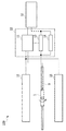
図1は、本発明の一実施の形態に係る磁気異方性評価装置100の構成を示すブロック図である。本実施形態の評価装置は、サンプルホルダ1、サンプルロッド9、電磁石15、直流電源13、電圧測定器14、コントローラ11、及び演算装置12を有して構成されるものである。演算装置12は、演算する機構ともいう。これらのうち、コントローラ11、直流電源13、電圧測定器14を含んで構成される要素を物理特性測定装置10という。サンプルホルダ1は、試料(サンプル)3を保持することができる。一方、サンプルホルダ1は、角度を変更できるギヤ機構を有したサンプルロッド9に取り付けられる。そして、磁界を印加する一対の電磁石15の中に配置される。これにより、その詳細が後述されるように、不図示の駆動機構によってサンプルロッド9が回転し、サンプルホルダ1に保持される試料3に対する磁界の印加角度、すなわち、磁界角度を相対的に変えることができる。なお、物理特性測定装置10に、角度を測定する機構であるコントローラ11と、直流電源13と、電圧測定器14とを有する角度を測定する機構を含めても良い。
FIG. 1 is a block diagram showing a configuration of a magnetic
また、試料3には、ホール抵抗を測定するための端子が取り付けられており、直流電流を印加する直流電源13および電圧測定器14と、電気的に接続される。また、コントローラ11は、電磁石15、サンプルロッド9、直流電源13等と電気的に接続され、磁界印加と、磁界強度と、磁界角度と、ホール抵抗測定電流とを制御する。更に、演算する機構12は、コントローラ11及び直流電源13等と電気的に接続され、磁気異方性の評価のための演算を実行する。なお、図2の試料3の磁性薄膜の磁化容易軸は、磁性薄膜表面に垂直方向である場合を示している。しかし、磁性薄膜の磁化容易軸が磁性薄膜表面に垂直な方向から傾いている場合でも、後述の内容と同様である。
Further, the
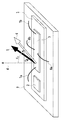
図2は、図1に示した磁気異方性評価装置の主要部を模式的に示す斜視図である。なお、図2には磁界角度測定機構として、ホールセンサ2を用いた例を示している。しかし、これに限定されるわけではない。図2において、サンプルロッド9はその棒状の一部が示されている。図1にて上述したように、サンプルロッド9にはサンプルホルダ1が取り付けられている。そして、サンプルホルダ1によって試料3が保持されている。なお、本実施形態の試料3は、測定する磁性薄膜が平坦なガラス基板等の上に形成されたものである。なお、磁性薄膜の表面上に、AuやPt等の金属からなる保護膜が形成されていてもよい。試料3としての磁性薄膜の膜厚は、1〜100nmが好ましい。より好ましくは、磁性薄膜の膜厚は、2〜20nmである。また、磁界の印加角度(磁界角度)θHは、平坦な磁性薄膜表面に対する垂直な磁化容易軸4から時計回りに測った角度である。
FIG. 2 is a perspective view schematically showing a main part of the magnetic anisotropy evaluation apparatus shown in FIG. FIG. 2 shows an example in which the
サンプルホルダ1において、試料3を保持する位置に対しサンプルホルダの長手方向に添った所定の距離の所定位置にホールセンサ2が設けられている。これにより、試料3に磁界を印加したときの磁界角度を測定することができる。本実施形態では、試料3の磁界角度を測定するため、ホールセンサ2は試料3と同様に板状の形状であることが好ましい。更に、ホールセンサの表面は、試料3を形成する磁性薄膜の表面と概略平行であることが好ましい。なお、本明細書において、概略平行とは、ホールセンサの表面と試料3の磁性薄膜表面のなす角が、0.5度より小さいことであり、好ましくは0.2度より小さいことである。また、ホールセンサ2は、試料3の近傍に配置されることが望ましい。本明細書において、近傍とは、磁界印加機構からの磁界が同一角度で印加される範囲のことである。そのため、ホールセンサ2と試料3とは、一つのサンプルホルダ1の平坦な同一面に配置される。さらに、試料3の表面には電流端子7a、7b、電圧端子8a、8bが取付けられる。これにより、試料3のホール抵抗を測定することができる。電流の流れる方向と電圧測定方向は、可能な限り直交するようにそれぞれの端子を取り付けることが好ましい。
In the
ホール抵抗測定機構は、試料3の磁性薄膜の表面に対して取り付けられる電流端子7a、7b、電圧端子8a、8b、および、直流電流を流すための直流電源13と直流電圧を測定する電圧測定器14を有して構成される。磁界を試料3に印加するとともに、直流電源13から電流端子7a、7bを介して試料3に一定の直流電流Iを流す。そして、電圧測定器14は、試料3の直流電流Iと直交する方向の起電圧Vを、電圧端子8a、8bを介して測定する。これらの電流Iと測定電圧Vとから、ホール抵抗RをR=V/Iとして算出することができる。
The Hall resistance measuring mechanism includes
なお、本明細書において、ホール抵抗とは、ホール効果により印加電流Iに直交する方向に起電力が生じるが、その起電力による電圧Vを印加電流Iで除したものである。 In this specification, the Hall resistance is an electromotive force generated in a direction orthogonal to the applied current I due to the Hall effect, and the voltage V due to the electromotive force is divided by the applied current I.
磁界印加機構は、磁力を発生させる電磁石15、および、電磁石に電流を供給する直流電源を有する。なお、図1では、コントローラ11に直流電源を含む。電磁石15は、超電導マグネットが強力な磁力を発生することができるため好ましい。
The magnetic field application mechanism includes an
磁界強度制御機構は、磁界印加機構に加えて、電磁石に供給する直流量を調節するためのコントローラ11を有する。本発明に係る磁気異方性評価においては、ゼロ磁界から飽和磁化以上の磁界まで、制御しながら印加する必要がある。更に、試料3面に対して逆方向にもゼロ磁界から飽和磁化以上の磁界まで、制御しながら印加する必要がある。
In addition to the magnetic field application mechanism, the magnetic field intensity control mechanism has a controller 11 for adjusting the amount of direct current supplied to the electromagnet. In the magnetic anisotropy evaluation according to the present invention, it is necessary to apply while controlling from a zero magnetic field to a magnetic field higher than saturation magnetization. Furthermore, it is necessary to control the magnetic field from the zero magnetic field to a magnetic field higher than the saturation magnetization in a reverse direction with respect to the surface of the
磁界角度制御機構は、サンプルホルダ1を図1に示す矢印の方向に回転させるためのギア機構を有するサンプルロッド9、および、回転を制御するコントローラ11を有する。なお、サンプルホルダ1を矢印の方向とは逆方向に回転させてもよい。例えば、サンプルロッド9の解放窓にギアと接続する回転部材を設け、回転部材にサンプルホルダ1を搭載する。このようなサンプルロッド9を超電導マグネットなどの電磁石15中に配置し、コントローラ11からギアの回転を制御することで、任意に試料3に対する磁界角度を変化させることができる。なお、ここでは、サンプルロッド9に回転機構を設けた例を示したが、サンプルロッド9ごと回転させる機構や、電磁石15を回転させる機構であっても構わない。
The magnetic field angle control mechanism has a
演算機構は、ホール抵抗の磁界角度に対する反転重ね合わせ、ホール抵抗の磁界角度に対する反転重ね合わせ、反転重ね合わせの磁界強度依存の傾きからのNHE成分の算出、ゼロ切片からAHE成分の算出、磁化角度θMの磁界依存の算出、磁気トルク曲線の算出、磁気トルク曲線のカーブフィッティング、磁気異方性の第1次成分Ku1及び第2次成分Ku2の算出、及び(全)磁気異方性Kuの算出を行う。 The calculation mechanism includes inversion superposition with respect to the magnetic field angle of the Hall resistance, inversion superposition with respect to the magnetic field angle of the Hall resistance, calculation of the NHE component from the gradient depending on the magnetic field strength of the inversion superposition, calculation of the AHE component from the zero intercept, and the magnetization angle. Calculation of magnetic field dependence of θ M , calculation of magnetic torque curve, curve fitting of magnetic torque curve, calculation of first and second components Ku1 and Ku2 of magnetic anisotropy, and (total) of magnetic anisotropy Ku Perform the calculation.
更に、試料3に対する印加磁界の角度(磁界角度)を測定する機構を設けてもよい。磁界角度測定機構には、実際の印加機構の角度あるいは試料3回転させる角度をエンコーダ等で機械的あるいは光学的に読み取る機構がある。また、前記のように、ホールセンサを用いて磁界角度を測定しても良い。ホールセンサを用いた方が、試料3の被検体の磁性薄膜の位置での角度を正確に測定できるため好ましい。
Furthermore, a mechanism for measuring the angle of the magnetic field applied to the sample 3 (magnetic field angle) may be provided. The magnetic field angle measuring mechanism includes a mechanism that mechanically or optically reads the angle of the actual applying mechanism or the angle of rotating the
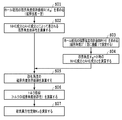
次に、本実施の形態にかかる磁気異方性評価処理の概略について説明する。図3は、この手順を示すフローチャートである。 Next, an outline of the magnetic anisotropy evaluation process according to the present embodiment will be described. FIG. 3 is a flowchart showing this procedure.
まず、図3のS01において、磁性体として試料3のホール抵抗Rの磁界角度依存曲線を求める。ここで測定されたホール抵抗R(θH)は、上述したように、正常ホール抵抗RNHE、および異常ホール抵抗RAHEなど、様々な抵抗成分を含む。
First, in S01 of FIG. 3, a magnetic field angle dependence curve of the Hall resistance R of the
次に、S02において、これら成分のうち、ホール抵抗RのNHE成分である正常ホール抵抗RNHEおよびホール抵抗RのAHE成分である異常ホール抵抗RAHEの磁界角度依存曲線を求める。すなわち、ホール抵抗Rの磁界角度依存曲線に関して、磁界角度に対する反転重ね合わせを行う。そうすることで、正常ホール抵抗RNHEと異常ホール抵抗RAHEの磁界角度依存曲線を求める。 Next, in S02, the magnetic field angle dependence curves of the normal Hall resistance R NHE that is the NHE component of the Hall resistance R and the abnormal Hall resistance R AHE that is the AHE component of the Hall resistance R among these components are obtained. That is, with respect to the magnetic field angle dependency curve of the Hall resistance R, inversion superposition with respect to the magnetic field angle is performed. By doing so, the magnetic field angle dependence curves of the normal Hall resistance R NHE and the abnormal Hall resistance R AHE are obtained.
次に、S03において、磁性体のホール抵抗Rの磁界強度依存曲線を求める。なお、磁界角度θH=0°、すなわち、面に垂直で固定する。 Next, in S03, a magnetic field strength dependence curve of the Hall resistance R of the magnetic material is obtained. It should be noted that the magnetic field angle θ H = 0 °, that is, it is fixed perpendicular to the surface.
更に、S04において、磁界角度θH=0時のNHE成分とAHE成分とを演算する。S02と同様にして、ホール抵抗Rの磁界強度依存曲線を、磁界強度に対して反転重ね合わせを行う。そうすることで、磁界角度θH=0°における正常ホール抵抗と異常ホール抵抗を求める。 Further, in S04, the NHE component and the AHE component when the magnetic field angle θ H = 0 is calculated. Similar to S02, the magnetic field strength dependence curve of the Hall resistance R is inverted and superimposed on the magnetic field strength. By doing so, normal Hall resistance and abnormal Hall resistance at the magnetic field angle θ H = 0 ° are obtained.
次に、S05において、S02で得た正常ホール効果と異常ホール効果による抵抗の磁界角度依存曲線と、S04で得た磁界角度θH=0°における正常ホール抵抗と異常ホール抵抗とから、磁化角度θMの磁界角度依存曲線θM(θH)を求める。 Next, in S05, the magnetization angle is determined from the magnetic field angle dependence curve of the resistance due to the normal Hall effect and the abnormal Hall effect obtained in S02 and the normal Hall resistance and the abnormal Hall resistance at the magnetic field angle θ H = 0 ° obtained in S04. θ M determine the magnetic field angle dependence curve θ M (θ H) of.
次に、S06において、S05で得た磁化角度の磁界角度依存曲線から、磁気トルク曲線、すなわち、磁気トルクの磁界角度依存性を演算する。 Next, in S06, the magnetic torque curve, that is, the magnetic field angle dependency of the magnetic torque is calculated from the magnetic field angle dependency curve of the magnetization angle obtained in S05.
なお、S02からS06までの演算を第1の演算ともいう。 Note that the calculation from S02 to S06 is also referred to as a first calculation.
最後に、S07において、S06で得た磁気トルク曲線から磁気異方性定数Kuを演算する。 Finally, in S07, the magnetic anisotropy constant Ku is calculated from the magnetic torque curve obtained in S06.
なお、S07を第2の演算ともいう。 Note that S07 is also referred to as a second calculation.
以下、上述した磁気異方性評価処理の各工程を詳細に説明する。 Hereafter, each process of the magnetic anisotropy evaluation process mentioned above is demonstrated in detail.
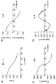
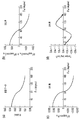
S01は、磁性体のホール抵抗Rの磁界角度依存曲線を測定する工程である。最初に、試料3を準備し、サンプルホルダ1の所定位置に搭載する。更に、試料3の表面に対して電流端子7a、7b、電圧端子8a、8bが取付けられる。その上で、サンプルホルダ1をサンプルロッド9の回転機構部分に取付ける。更に、サンプルロッド9を電磁石15中に配置する。上記にようにしてサンプルをセットした後、磁気角度に係るパラメータαの初期化を行う。また、電磁石15に所定の電流を流すことで試料3に一定の磁界を印加する。ここで、印加する磁界強度は、例えば、3000kA/m〜8000kA/mである。そして、一定の磁界強度を印加した状態で、ホール抵抗Rを測定する。ホール抵抗の測定は、前記したようにホール抵抗測定機構により行う。更に、磁界角度を変化させて、ホール抵抗Rを測定する。具体的には、磁界を印加する角度である磁界角度θHをα1、例えば、本実施形態では、初期値として、試料3の上面に対して垂直方向、すなわち、磁化容易軸4から0度とし、この磁界角度θH=α1でのホール抵抗R(θH)を測定する。そして、磁界角度を所定角度分増したα2に変化させて、磁界角度θH=α2でのホール抵抗R(θH)を測定する。これを、上記所定角度分を増しつつ繰り返しながら、磁界角度θHを0度から180度まで変化させて、磁界角度θHが0度から180度までのホール抵抗R(θH)を測定する。こうすることで、ホール抵抗Rの磁界角度依存曲線を得る。図4(a)は、この磁界角度依存曲線の一例を示している。
S01 is a step of measuring a magnetic field angle dependence curve of the Hall resistance R of the magnetic material. First, a
この測定で得られるホール抵抗Rは、一方で下記の成分で構成されるものとして表すことができる。 On the other hand, the Hall resistance R obtained by this measurement can be expressed as comprising the following components.
R=R0 NHEHcosθH+R0 AHEcosθM+R0 MRsin2θM+R0 B 式(3)
ここで、
R0 NHE : θH=0で測定したホール抵抗から得られるNHE成分
R0 AHE : θH=0で測定したホール抵抗から得られるAHE成分
R0 MR: MR(磁気抵抗)成分
R0 B : バックグラウンド抵抗、この抵抗は下地層や配線などの抵抗を示す。
R = R 0 NHE H cos θ H + R 0 AHE cos θ M + R 0 MR sin 2 θ M + R 0 B Formula (3)
here,
R 0 NHE : NHE component obtained from Hall resistance measured at θ H = 0 R 0 AHE : AHE component obtained from Hall resistance measured at θ H = 0 R 0 MR : MR (magnetoresistance) component R 0 B : Background resistance, which indicates the resistance of the underlying layer or wiring.
θH : 磁化容易軸4と磁界方向6のなす磁界角度
θM :磁化容易軸4と磁化方向5のなす角
θ H : Magnetic field angle formed by the easy magnetization axis 4 and the magnetic field direction 6 θ M : Angle formed by the easy magnetization axis 4 and the
S02では、S01で得た測定値R(θH)から、MR成分およびバックグラウンド抵抗を除去して、正常ホール抵抗RNHEおよび異常ホール抵抗RAHEによって表される磁界角度依存曲線を演算する工程である。 In S02, the MR component and the background resistance are removed from the measured value R (θ H ) obtained in S01, and a magnetic field angle dependence curve represented by the normal Hall resistance R NHE and the abnormal Hall resistance R AHE is calculated. It is.
すなわち、MR成分などを磁界角度θHに対するホール抵抗の測定値R(θH)の反転重ね合わせをすることによって除去する。具体的には、磁界角度がθHと180−θHでの測定データR(θH)の差分をとることで除去する。すなわち、(R(θH)−R(180−θH))/2を計算し、その結果、
(R(θH)−R(180−θH))/2=R0 NHEHcosθH+R0 AHEcosθM 式(4)
を得ることができる。図4(b)は、正常ホール抵抗RNHEおよび異常ホール抵抗RAHEの磁界角度依存曲線の一例を示している。ここで、MR成分が消去されるのは、磁界角度に対する対称性から、磁界角度θHと180−θHでのθMは等しいためである。また、バックグラウンド抵抗は磁場角度に依存せず、一定であるためである。
That is, the MR component and the like are removed by reversing and superposing the measured value R (θ H ) of the Hall resistance with respect to the magnetic field angle θ H. Specifically, the magnetic field angle is removed by taking the difference between the measurement data R (θ H ) at θ H and 180−θ H. That is, (R (θ H ) −R (180−θ H )) / 2 is calculated, and as a result,
(R (θ H ) −R (180−θ H )) / 2 = R 0 NHE H cos θ H + R 0 AHE cos θ M Formula (4)
Can be obtained. FIG. 4B shows an example of a magnetic field angle dependency curve of the normal Hall resistance R NHE and the abnormal Hall resistance R AHE . Here, the MR component is erased because the magnetic field angle θ H is equal to θ M at 180−θ H because of symmetry with respect to the magnetic field angle. Further, the background resistance is constant regardless of the magnetic field angle.
S03では、磁性体のホール抵抗Rの磁界強度依存曲線を測定する工程である。S01と同じように、最初に、電磁石15中に試料3をセットした後、電磁石15に所定の電流を流すことで試料3に磁界を印加する。ただし、S03では、磁界角度を試料3の上面に対して垂直方向、すなわち、θH=0°で固定する。その上で、磁界強度を変化させて、それぞれの磁界強度でのホール抵抗Rを測定する。ホール抵抗の測定は、前記したようにホール抵抗測定機構により行う。例えば、印加する磁界強度を0kA/m→+5600kA/m→0kA/m→逆向きの磁界として−5600kA/m→0kA/mと変化させていく中で、10kA/mおきにホール抵抗Rを測定する。このように、印加する磁界強度を変化させると、図5に示すようなヒステリシスループを描く曲線が得られる。なお、印加する磁界強度の最大値は±5600kA/mである必要はなく、±3000kA/m〜±8000kA/mであればよい。こうすることで、ホール抵抗Rの磁界強度依存曲線を得る。
Step S03 is a step of measuring the magnetic field strength dependence curve of the Hall resistance R of the magnetic material. As in S01, first, the
S04は、磁界角度θHが0°における正常ホール抵抗R0 NHEと異常ホール抵抗R0 AHEの成分を演算する工程である。 S04 is a step of calculating the components of the normal Hall resistance R 0 NHE and the abnormal Hall resistance R 0 AHE when the magnetic field angle θ H is 0 °.
ここではまず、S03で得たホール抵抗Rの磁界強度依存曲線を、磁界強度に対する反転重ね合わせR(H)−R(-H)を行う。こうして、
(R(H)−R(-H))/2=R0 NHEH+R0 AHE 式(5)
を計算する。そして、θH=0°のときは、磁化角度θMは0°であるため、cosθM は1となる。図5は磁界強度依存曲線の一例を示している。このとき、上述したように、磁界角度に対する対称性から、MR成分、バックグラウンド成分は除去されている。
Here, first, the magnetic field strength dependence curve of the Hall resistance R obtained in S03 is subjected to inversion superposition R (H) -R (-H) with respect to the magnetic field strength. Thus,
(R (H) -R (-H)) / 2 = R 0 NHE H + R 0 AHE formula (5)
Calculate When θ H = 0 °, the magnetization angle θ M is 0 °, so cos θ M is 1. FIG. 5 shows an example of the magnetic field strength dependency curve. At this time, as described above, the MR component and the background component are removed from the symmetry with respect to the magnetic field angle.
ここで、磁界強度が測定対象の磁性体の飽和磁界よりも大きい部分、例えば、図5においてヒステリシスループが閉じている部分では、AHE成分は変化せず、NHE成分のみが変化する。このため、磁界の変化量ΔHに対するホール抵抗変化ΔRは、正常ホール抵抗R0 NHEとなる。つまり、図5のΔR/ΔH=R0 NHEである。 Here, in the portion where the magnetic field strength is larger than the saturation magnetic field of the magnetic substance to be measured, for example, the portion where the hysteresis loop is closed in FIG. 5, the AHE component does not change, and only the NHE component changes. For this reason, the Hall resistance change ΔR with respect to the magnetic field change amount ΔH becomes the normal Hall resistance R 0 NHE . That is, ΔR / ΔH = R 0 NHE in FIG.
また、磁界強度が測定対象の磁性体の飽和磁界よりも小さい所、例えば、図5においてヒステリシスループが開いている部分は、一定のAHE成分と磁界強度Hに比例するNHE成分とによるものである。このため、異常ホール抵抗R0 AHEは、磁界強度依存性のゼロ切片として得られる。つまり、図5の異常ホール抵抗R0 AHEである。 Further, where the magnetic field strength is smaller than the saturation magnetic field of the magnetic substance to be measured, for example, the portion where the hysteresis loop is opened in FIG. 5 is due to the constant AHE component and the NHE component proportional to the magnetic field strength H. . Therefore, the anomalous Hall resistance R 0 AHE is obtained as a zero intercept that is magnetic field strength dependent. That is, the abnormal Hall resistance R 0 AHE in FIG.
S05は、磁化角度の磁界角度依存曲線を演算する工程である。具体的には、S02で得た正常ホール効果と異常ホール効果による抵抗の磁界角度依存曲線である式(4)に、S04で得た正常ホール抵抗R0 NHEと異常ホール抵抗R0 AHEを代入する。 S05 is a step of calculating a magnetic field angle dependence curve of the magnetization angle. Specifically, the normal Hall resistance R 0 NHE and the abnormal Hall resistance R 0 AHE obtained in S04 are substituted into Equation (4) which is a magnetic field angle dependence curve of the resistance due to the normal Hall effect and the abnormal Hall effect obtained in S02. To do.
まず、式(4)を変形し、下記式(6)を得る、その上で、S04で得た正常ホール抵抗R0 NHEを代入する。このようにして得られた曲線が図4(c)である。 First, the equation (4) is modified to obtain the following equation (6), and then the normal Hall resistance R 0 NHE obtained in S04 is substituted. The curve thus obtained is FIG. 4 (c).
R0 AHEcosθM=(R(θH)−R(180−θH))/2−R0 NHEHcosθH 式(6) R 0 AHE cos θ M = (R (θ H ) −R (180−θ H )) / 2−R 0 NHE H cos θ H formula (6)
さらに、両辺をS04で得た異常ホール抵抗R0 AHEで除することで、最大値を1とする規格化を行う。これは規格化された磁化の膜面垂直成分と等しい。こうすることで、下記式(7)で示される磁化角度θMの磁界角度依存曲線を演算する。 Further, normalization is performed with the maximum value being 1 by dividing both sides by the abnormal Hall resistance R 0 AHE obtained in S04. This is equal to the normalized film surface perpendicular component of magnetization. By doing so, the magnetic field angle dependence curve of the magnetization angle θ M expressed by the following formula (7) is calculated.
cosθM=((R(θH)−R(180−θH))/2−R0 NHEHcosθH)/R0 AHE 式(7)
cos θ M = ((R (θH) −R (180−θH)) / 2−R 0 NHE Hcos θ H ) / R 0 AHE equation (7)
S06は、S05で得た磁化角度θMの磁界角度依存曲線から、磁気トルク曲線を演算する工程である。すなわち、上述した磁化角度θMで記述される磁気トルクの式(2)に、S05で得られたcosθMより得られる式(7)を代入して、磁気トルク曲線、すなわち、磁気トルクの磁界角度依存性を得る。図4(d)はこのトルクの磁界角度依存性の一例を示している。 S06 is a step of calculating a magnetic torque curve from the magnetic field angle dependence curve of the magnetization angle θ M obtained in S05. That is, the magnetic torque curve, that is, the magnetic field of the magnetic torque is substituted by substituting the equation (7) obtained from cos θ M obtained in S05 for the magnetic torque equation (2) described by the magnetization angle θ M described above. Get angular dependence. FIG. 4D shows an example of the dependence of this torque on the magnetic field angle.
T=HMssin(θH−θM) 式(2)
ここで、
θM=cos-1(((R(θH)−R(180−θH))/2−R0 NHEHcosθH)/R0 AHE) 式(8)
T = HM s sin (θ H −θ M ) Equation (2)
here,
θ M = cos −1 (((R (θH) −R (180−θH)) / 2−R 0 NHE Hcos θ H ) / R 0 AHE ) (8)
S07は、S06で得た磁気トルク曲線から磁気異方性定数Kuを演算する工程である。先ず、磁気トルク曲線の2θM、4θM成分をカーブフィッティングによる求める。次に、以下の磁気異方性エネルギーの磁気トルク関係式(式(9))から、磁気異方性定数の第1次成分Ku1、第2次成分Ku2を算出する。 S07 is a step of calculating the magnetic anisotropy constant K u from magnetic torque curve obtained in S06. First, 2θ M and 4θ M components of the magnetic torque curve are obtained by curve fitting. Next, a magnetic torque relational expression of the following magnetic anisotropy energy (equation (9)), the first-order component K u1 of the magnetic anisotropy constant, for calculating a second order component K u2.
T=−(Ku1+Ku2)sin2θM+(Ku2/2)sin4θM 式(9)
次に、全磁気異方性定数Kuを磁気異方性エネルギーの関係式(式(10))で算出する。
T = − (K u1 + K u2 ) sin 2θ M + (K u2 / 2) sin 4θ M formula (9)
Then calculated by the equation of the magnetic anisotropy energy total magnetic anisotropy constant K u (formula (10)).
Ku=Ku1+Ku2+2Ms 2 式(10) K u = K u1 + K u2 + 2M s 2 formula (10)
次に、本実施の形態にかかる磁気異方性評価方法の変形例について説明する。 Next, a modified example of the magnetic anisotropy evaluation method according to the present embodiment will be described.
前記S01〜S07の工程では、磁界角度θHを正確に評価することが必要である。特に、グラニュラー磁性薄膜では、ホール抵抗の測定値における正常ホール抵抗成分R0 NHEおよび磁気抵抗成分R0 MRの影響が大きい。そのため、異常ホール抵抗成分R0 AHEを正しく導出するには、θHの評価精度を高める必要がある。そこで、本実施の形態の変形例では、磁気異方性評価装置が磁界角度θHとして、磁界角度測定機構又は、磁界角度測定手法により得られた測定値を用いる。これにより、評価時の設定値を用いていたのに対して、磁界角度θHの評価精度が高まり、その結果、異常ホール抵抗成分R0 AHEをより正しく導出でき、磁気異方性Kuをより正しく評価できる。 Wherein in the S01~S07 step, it is necessary to accurately evaluate the magnetic field angle theta H. In particular, the granular magnetic thin film is greatly affected by the normal Hall resistance component R 0 NHE and the magnetoresistance component R 0 MR in the measured Hall resistance. Therefore, in order to correctly derive the abnormal Hall resistance component R 0 AHE , it is necessary to improve the evaluation accuracy of θ H. Therefore, in the modification of the present embodiment, the magnetic anisotropy evaluation apparatus uses a measurement value obtained by a magnetic field angle measurement mechanism or a magnetic field angle measurement method as the magnetic field angle θ H. Thus, for example G with the set value at the time of evaluation, increased evaluation accuracy of the magnetic field angle theta H, as a result, it can more accurately derive the anomalous Hall resistance component R 0 AHE, the magnetic anisotropy K u Can be evaluated more correctly.
本実施の形態の変形例における磁気異方性評価装置では、磁界角度測定機構として、ホールセンサ2を用いる。ホールセンサ2は、固有方向の磁界強度を測定するものである。この場合、ホールセンサの表面に垂直方向の成分の磁界強度を測定する。磁界と電流に垂直方向にホール電流を生じるホール効果より測定できる。本実施の形態の変形例では、ホールセンサ2の磁界測定方向と試料3の磁化容易軸4とのずれを補正する工程と、ホールセンサ2の磁界強度を測定する工程と、磁界角度θHを算出する工程を含む。これにより、評価時の試料3の磁化容易軸4方向と磁界強度θHを高い精度で評価できる。
In the magnetic anisotropy evaluation apparatus according to the modification of the present embodiment, the
具体的な方法を次に示す。ホールセンサ2の磁界測定方向と試料3の磁化容易軸4とのずれを補正する工程は、試料3においてθH=0°、したがってθM=0°で最大値を取ることを利用し、その時点でのホールセンサ2の磁界強度を磁化容易軸4方向の磁界強度HZとする工程である。これにより、データ解析の際に測定データのθH依存性の原点を調整することができる。
The specific method is as follows. The step of correcting the deviation between the magnetic field measurement direction of the
次に、ホールセンサ2の磁界強度を測定する工程は、試料3の磁性薄膜のホール抵抗の磁界角度依存性の測定時に、同時にホールセンサ2により磁界強度Hも測定する。つまり、ホールセンサ2の磁界強度Hの磁界角度依存性を測定する。この曲線は、磁界角度θHが0°を頂点とするコサイン曲線をとる。そして、例えば、ホールセンサ2による磁界強度Hに対する試料3のホール抵抗の曲線を得ることができる。
Next, in the step of measuring the magnetic field strength of the
磁界角度θHを算出する工程は、ホールセンサ2で読み取った磁界強度Hと磁化容易軸4方向の磁界強度Hzから、磁界角度θHを以下の式で算出する。こうすることで、ホールセンサ2で読み取った磁界強度Hを用いて、精度よく磁界角度θHを得ることができる。
Calculating a magnetic field angle theta H from the magnetic field intensity H z of the magnetic field strength H and the magnetization easy axis four directions read by the
θH=cos-1(H/Hz) 式(11)
θ H = cos −1 (H / H z ) Equation (11)
試料3は、例えば、ガラスや酸化物結晶などの絶縁体からなり、平坦な面を有する基板上に、磁性薄膜が形成されている。測定できる材料は磁気異方性を有する材料であれば特に限定されない。また、測定に用いる磁性体は所定の厚さを有する薄膜状態の場合について説明するが、これに限定されるものではない。所定の形状に成形されたバルクでも測定することは可能である。なお、磁性薄膜の表面上に、AuやPt等の金属からなる保護膜が形成されていてもよい。基板の厚さは、0.2〜10mmが好ましい。磁性薄膜の膜厚は、1〜100nmが好ましい。より好ましくは、その膜厚は、1〜20nmである。こうすることで、磁性薄膜のハンドリング性がよく、また、本来の磁性薄膜の特性および磁気記録媒体として実際に使用される磁性薄膜の膜厚での特性に近い値が得られる。例えば、L10型規則合金からなる磁性薄膜は、膜厚によって、本来の磁性薄膜の特性が変わってしまうことがある。特に、磁性薄膜の膜厚が20nmより厚くなると、規則性が乱され、磁気記録媒体として使用される磁気異方性定数と大きく異なる。そのため、本来の磁性薄膜の特性が得られる膜厚、および磁気記録媒体として使用される膜厚で測定する必要がある。
The
しかしながら、このような膜厚の磁性薄膜において、磁気トルクの測定出力が小さく、磁気異方性定数を測定しようとした場合、基板上に形成された磁性薄膜の試料は大きな面積を必要とする。そのため、従来の機械的な磁気トルクを測定する方法では、基板などからの反磁界の影響や力学的ノイズの影響で、正確な磁気異方性定数を測定することが困難であった。例えば、従来の機械的な磁気トルクによる測定では、ノイズレベルのRMS(二乗平均平方根)は、10-5Nmが限界であり、それ以下の測定はできなかった。厚い膜厚においても反磁界の影響や力学的ノイズの影響で、正確に磁気異方性定数を測定することは難しいが、特に、試料の磁性薄膜が1nmから20nmと薄い膜厚の場合、測定が困難であった。なお、ノイズレベルとは、信号成分に存在する高周波の雑音成分のレベルである。ここでは、そのレベルをRMS値で示した。ノイズレベルのRMSは、ノイズの程度を示す指標の一つである。 However, in the magnetic thin film having such a film thickness, the measurement output of the magnetic torque is small, and when trying to measure the magnetic anisotropy constant, the magnetic thin film sample formed on the substrate requires a large area. For this reason, it is difficult to measure an accurate magnetic anisotropy constant by the conventional method of measuring the magnetic torque due to the influence of the demagnetizing field from the substrate or the like or the influence of mechanical noise. For example, in the conventional measurement by mechanical magnetic torque, the noise level RMS (root mean square) is limited to 10 −5 Nm, and measurement below that cannot be performed. Although it is difficult to accurately measure the magnetic anisotropy constant due to the influence of the demagnetizing field and mechanical noise even at a thick film thickness, especially when the magnetic thin film of the sample is as thin as 1 to 20 nm. It was difficult. The noise level is the level of a high frequency noise component present in the signal component. Here, the level is indicated by the RMS value. The RMS of the noise level is one of indexes indicating the degree of noise.
一方、本実施の形態の磁気異方性評価装置及び磁気異方性評価方法では、磁性薄膜に端子をつけ、磁性薄膜のみを測定するので、反磁界の影響がほとんどない。また、磁性薄膜を電気的に測定できるので、力学的ノイズを低減することができる。そのため、上記のような、1nmから20nmと薄い膜厚の試料3でも正確な磁気異方性定数を測定することができる。例えば、本実施の形態の方法による磁気トルクによる測定では、ノイズレベルのRMSを、10-9Nm以下に低減することができた。磁性薄膜の膜厚が1nmから10nmであっても、良好に測定することができる。
On the other hand, in the magnetic anisotropy evaluation apparatus and the magnetic anisotropy evaluation method of the present embodiment, since a terminal is attached to the magnetic thin film and only the magnetic thin film is measured, there is almost no influence of the demagnetizing field. Further, since the magnetic thin film can be electrically measured, mechanical noise can be reduced. Therefore, an accurate magnetic anisotropy constant can be measured even with the
発明者が従来の磁気トルクを力学的に直接測定する方法によりグラニュラー構造を備えた磁性薄膜の磁気異方性評価を実際に行ったところ、グラニュラー化に伴う磁気トルクの減少、磁性薄膜の厚膜、及び測定レベルの限界により、磁気異方性を正しく算出できないことを確認しているが、本実施の形態の磁気異方性評価装置及び磁気異方性評価方法を用いることにより、磁気異方性を正しく算出することが可能となる。 The inventors actually evaluated the magnetic anisotropy of a magnetic thin film having a granular structure by a conventional method of directly measuring the magnetic torque. As a result, the magnetic torque decreased with the increase in granularity, and the magnetic thin film became thicker. In addition, it has been confirmed that the magnetic anisotropy cannot be calculated correctly due to the limit of the measurement level, but by using the magnetic anisotropy evaluation apparatus and the magnetic anisotropy evaluation method of the present embodiment, It becomes possible to calculate the sex correctly.
なお、本実施の形態では、物理特性測定装置10とは別に演算装置12を接続し演算を行ったが、物理特性測定装置内に演算する機構を設けて演算を行ってもよい。
In the present embodiment, the calculation is performed by connecting the
本実施例の磁気異方性評価装置は、Quantum Design社の物理特性測定装置10(Physical Property Measurement System; PPMS)と、ホール抵抗測定用サンプルロッド9からなる。物理特性測定装置10は、少なくとも、磁性体に磁界を印加する機構(サンプルホルダ1、サンプルロッド9、及び電磁石15)と、コントローラ11と、直流電源13と、電圧測定器14とを有する角度を測定する機構とを有し、演算装置12と電気的に接続している。この物理特性測定装置10のノイズレベルのRMSは、10-9Nm以下であった。サンプルロッド9は、物理特性測定装置10が印加する磁界方向6と測定用の試料3の磁化容易軸4の間の磁界角度θHを変えられるように、測定用の試料3を一軸回転する機構、すなわち、磁界方向と磁性体の磁化容易軸の間の角度を変えることができる機構を有する。サンプルロッド9には、試料3のホール抵抗測定とホールセンサ2の読み出しを同時に行うように測定端子が配置されたサンプルホルダ1を配置した。試料3のホール抵抗測定は、磁性体の磁化容易軸4、電圧方向、および、電流方向が互い直交するように電圧端子8a、8bと電流端子7a、7bを配置し、4端子法で行った。これにより、磁化容易軸4の磁化に比例した異常ホール抵抗を評価できる。本実施例のホールセンサ2は、FW Bell社製のBHA−921を用いた。
The apparatus for evaluating magnetic anisotropy of the present embodiment includes a physical property measurement apparatus 10 (Physical Property Measurement System; PPMS) manufactured by Quantum Design, and a
本実施例で評価した磁性体は、磁気記録媒体に一般に用いられるガラス基板に、L10型規則合金のFePt磁性結晶粒と、前記磁性結晶粒を取り囲むカーボン(C)非磁性部とからなる磁性薄膜を膜厚4nmで形成したものである。本実施例では、磁性薄膜の膜厚を4nmで形成したが、磁性薄膜は連続膜であればよく、また、その膜厚は、測定の可能な1nm以上が好ましく、2nm以上がより好ましい。また、L10型規則合金のような規則合金を含む磁性薄膜の場合は特性変化を抑えるために、10nm未満であればよい。非磁性部のカーボン(C)は体積分率で20%添加されており、これによりFePt−C磁性薄膜はグラニュラー構造を有する。FePt−C磁性薄膜の直下にはMgO(酸化マグネシウム)を含む下地層が形成されている。測定に際しては、板厚0.6mm、長さ3mm、幅8mmの直方体に切り出された試料3を用いた。
Magnetic evaluated in this embodiment, consists of a glass substrate generally used in a magnetic recording medium, the L1 0 type ordered alloy FePt magnetic crystal grains, and the magnetic crystal grains surround the carbon (C) a non-magnetic portion-magnetic A thin film is formed with a thickness of 4 nm. In this embodiment, the magnetic thin film is formed with a thickness of 4 nm. However, the magnetic thin film may be a continuous film, and the film thickness is preferably 1 nm or more, more preferably 2 nm or more, which can be measured. In the case of magnetic thin film containing ordered alloy such as L1 0 type ordered alloy to suppress changes in the characteristics, it may be less than 10 nm. Carbon (C) in the nonmagnetic part is added in a volume fraction of 20%, whereby the FePt-C magnetic thin film has a granular structure. An underlayer containing MgO (magnesium oxide) is formed immediately below the FePt-C magnetic thin film. In the measurement, a
磁性薄膜の磁気異方性を評価するために、実施の形態と同様の方法を用い、磁性薄膜のホール抵抗の値を用いてトルク曲線を算出し、磁気異方性定数を演算した。 In order to evaluate the magnetic anisotropy of the magnetic thin film, a torque curve was calculated using the value of the Hall resistance of the magnetic thin film using the same method as in the embodiment, and the magnetic anisotropy constant was calculated.
まず、図3のS01において、磁性体のホール抵抗Rの磁界角度依存曲線を測定する。なお、磁界強度を一定とする。ここで測定されたホール抵抗R(θH)は、正常ホール抵抗RNHE、および異常ホール抵抗RAHEによる抵抗の他に様々な抵抗成分を含む。なお、本実施例のホール抵抗測定は、印加磁界5600kA/m、電流300μAで行った。また、磁界角度θHを設定値0〜180度を1度刻みで変化させた。 First, in S01 of FIG. 3, the magnetic field angle dependence curve of the Hall resistance R of the magnetic material is measured. The magnetic field strength is constant. The measured Hall resistance R (θ H ) includes various resistance components in addition to the normal Hall resistance R NHE and the resistance due to the abnormal Hall resistance R AHE . The Hall resistance measurement of this example was performed with an applied magnetic field of 5600 kA / m and a current of 300 μA. In addition, the magnetic field angle θ H was changed from 0 to 180 degrees in increments of 1 degree.
次に、S02において、これら成分のうち、ホール抵抗RのNHE成分である正常ホール抵抗RNHEおよびホール抵抗RのAHE成分である異常ホール抵抗RAHEの磁界角度依存曲線を求める。すなわち、ホール抵抗Rの磁界角度依存曲線を、磁界角度に対して反転重ね合わせを行う。そうすることで、正常ホール抵抗RNHEと異常ホール抵抗RAHEによる磁界角度依存曲線を演算する。 Next, in S02, the magnetic field angle dependence curves of the normal Hall resistance R NHE that is the NHE component of the Hall resistance R and the abnormal Hall resistance R AHE that is the AHE component of the Hall resistance R among these components are obtained. That is, the magnetic field angle dependence curve of the Hall resistance R is inverted and superimposed with respect to the magnetic field angle. By doing so, the magnetic field angle dependence curve by the normal Hall resistance R NHE and the abnormal Hall resistance R AHE is calculated.
次に、S03において、磁性体のホール抵抗Rの磁界強度依存曲線を測定する。なお、磁界角度θH=0°すなわち、面に垂直で固定する。 Next, in S03, the magnetic field strength dependence curve of the Hall resistance R of the magnetic material is measured. The magnetic field angle θ H = 0 °, that is, it is fixed perpendicular to the surface.
更に、S04において、磁界角度θH=0°時のNHE成分とAHE成分とを演算する。ホール抵抗Rの磁界強度依存曲線を、磁界強度に対して反転重ね合わせを行う。そうすることで、磁界角度θH=0°における正常ホール抵抗と異常ホール抵抗を演算する。 Further, in S04, the NHE component and the AHE component when the magnetic field angle θ H = 0 ° is calculated. The magnetic field strength dependence curve of the Hall resistance R is inverted and superimposed on the magnetic field strength. By doing so, the normal Hall resistance and the abnormal Hall resistance at the magnetic field angle θ H = 0 ° are calculated.
次に、S05において、S02で得た正常ホール効果と異常ホール効果による抵抗の磁界角度依存曲線と、S04で得た磁界角度θH=0°における正常ホール抵抗と異常ホール抵抗とから、磁化角度の磁界角度依存曲線を演算する。 Next, in S05, the magnetization angle is determined from the magnetic field angle dependence curve of the resistance due to the normal Hall effect and the abnormal Hall effect obtained in S02 and the normal Hall resistance and the abnormal Hall resistance at the magnetic field angle θ H = 0 ° obtained in S04. The magnetic field angle dependence curve is calculated.
次に、S06において、S05で得た磁化角度の磁界角度依存曲線から、磁気トルク曲線、すなわち、トルクの磁界角度依存性を演算する。 Next, in S06, the magnetic torque curve, that is, the magnetic field angle dependence of the torque is calculated from the magnetic field angle dependence curve of the magnetization angle obtained in S05.
最後に、S07において、S06で得た磁気トルク曲線から磁気異方性定数Kuを演算する。 Finally, in S07, the magnetic anisotropy constant Ku is calculated from the magnetic torque curve obtained in S06.
S01〜S07の工程により、実施の形態1で説明された式(1)〜(10)を得ることができる。 By the steps S01 to S07, the formulas (1) to (10) described in the first embodiment can be obtained.
図4(a)に、実施例のホール抵抗の磁界角度依存性の測定データを示す。図4(b)に、S02時のデータ(式(3))、図4(c)に、S05時のデータ(式(5))、図4(d)に、(S06)後のデータ(式(8))、すなわち、磁気トルク曲線を示す。また、図5はS05で用いたホール抵抗の磁界強度依存性(式(4)である。正常ホール抵抗R0 NHEは磁場範囲4000kA/m〜5600kA/mおよび−5600kA/m〜−4000kA/mでの傾きの平均として求めた。S06時の磁気トルク曲線は、図4(d)の通り、正弦波形状をしており理論式でフィッティングは容易である。このフィッティングの結果、得られた磁気異方性はKu=23.6Merg/cm3であった。これは、本実施例の磁性薄膜に妥当な値であった。また、フィッティングにおける残差平方和は0.023(Merg/cm3)2/deg.であり、問題なくフィッティングできていることがわかった。なお、残差平方和とは、データ曲線とフィッティング曲線との間の数値差を平方したものの和であり、フィッティングの不一致を評価する尺度である。磁気異方性Ku=10〜70Merg/cm3程度の試料においては、残差平方和は、1.0(Merg/cm3)2/deg.以下であることが好ましい。より好ましくは、残差平方和は、(Merg/cm3)2/deg.は、0.1以下である。 FIG. 4A shows measurement data of the magnetic field angle dependence of the Hall resistance of the example. 4B shows data at S02 (formula (3)), FIG. 4C shows data at S05 (formula (5)), FIG. 4D shows data after (S06) ( Formula (8)), ie, a magnetic torque curve, is shown. 5 shows the magnetic field strength dependence of the Hall resistance used in S05 (formula (4)). The normal Hall resistance R 0 NHE has a magnetic field range of 4000 kA / m to 5600 kA / m and −5600 kA / m to −4000 kA / m. The magnetic torque curve at S06 has a sine wave shape as shown in Fig. 4 (d) and is easy to fit with a theoretical formula. The anisotropy was K u = 23.6 Merg / cm 3, which was a reasonable value for the magnetic thin film of this example, and the residual sum of squares in the fitting was 0.023 (Merg / cm 3) 2 / deg is. were found to be able to fit without problems. Note that the residual sum of squares, the sum der although squared numerical difference between the data curve and fitting curve Is a measure for evaluating the disagreement fitting. In anisotropy K u = 10~70Merg / cm 3 order of the sample, the residual sum of squares, 1.0 (Merg / cm 3) 2 / deg. Or less More preferably, the residual sum of squares (Merg / cm 3 ) 2 / deg.
なお、本実施例では、磁界角度θHを設定値0〜180度を1度刻みで変化させたが、例えば、磁気トルク曲線が得られる程度に、偶数の値の角度刻みで変化させたり、ランダムに角度刻を変化させてもよい。 In the present embodiment, although varied 1 degree increments the set value 0-180 degrees field angle theta H, for example, to the extent that the magnetic torque curve is obtained, or varied angular increments of even number, The angle increment may be changed at random.
本実施例は、磁界角度をホールセンサによる測定値ではなく、装置の設定値とした以外は、実施例と共通である。 The present embodiment is the same as the embodiment except that the magnetic field angle is not a measured value by the Hall sensor but a set value of the apparatus.
図6(a)に、比較例の測定データを示す。図6(b)に、S02時のデータ(式(3))、図6(c)に、S05時のデータ(式(5))、図6(d)に、S06時のデータ(式(8)磁気トルク曲線)を示す。図6(d)に示すように、理論的に得られるべき正弦波波形から多少波形が乱れるが、理論式での正確なフィッティングは可能であった。フィッティングを実行した場合の残差平方和は0.505(Merg/cm3)2/deg.であり、実施例と比べフィッティング精度が若干劣るが、測定に支障はなかった。フィッティング精度が悪いことがわかった。これは、本実験例のように装置の設定値を用いた場合より、ホールセンサによって磁界角度測定した方が、磁界角度の測定精度が若干良いためであると考えられる。 FIG. 6A shows the measurement data of the comparative example. FIG. 6B shows data at S02 (expression (3)), FIG. 6C shows data at S05 (expression (5)), and FIG. 6D shows data at S06 (expression ( 8) Magnetic torque curve). As shown in FIG. 6D, the waveform is somewhat disturbed from the theoretically obtained sine wave waveform, but accurate fitting with the theoretical formula was possible. The residual sum of squares when the fitting is executed is 0.505 (Merg / cm 3 ) 2 / deg. Although the fitting accuracy was slightly inferior to that of the example, there was no hindrance to the measurement. It turned out that fitting accuracy was bad. This is considered to be because the measurement accuracy of the magnetic field angle is slightly better when the magnetic field angle is measured by the Hall sensor than when the set value of the apparatus is used as in this experimental example.
本比較例では、磁気トルク曲線を力学的に測定した。測定には、有限会社ハヤマ製のトルク磁力計を用いた。また、測定に使用する磁性体は実施例と同じ試料を用いた。 In this comparative example, the magnetic torque curve was measured dynamically. For the measurement, a torque magnetometer manufactured by Hayama Co., Ltd. was used. Moreover, the same sample as the Example was used for the magnetic body used for the measurement.
図7に磁気トルク曲線を示す。図7に示すように、0度から22度付近まで正のトルク、22度付近から90度付近まで負のトルク、90度から157度付近まで正のトルク、157度付近から180度付近まで負のトルクとなった。また、ノイズによる高周波成分が多かった。そのため、式(9)によるカーブフィッティングに対して、大きな誤差を生じた。ノイズレベルのRMSは、10-5Nm程度であった。また、カーブフィッティングによる残差平方和は、3.05(Merg/cm3)2/deg.で実施例と比べ著しくフィッティング精度が悪いことがわかった。そのため、測定ごとにKuの測定値が大きく変動し、正確な測定は困難であった。 FIG. 7 shows a magnetic torque curve. As shown in FIG. 7, a positive torque from 0 to 22 degrees, a negative torque from 22 to 90 degrees, a positive torque from 90 to 157 degrees, and a negative torque from 157 to 180 degrees. Torque. Moreover, there were many high frequency components by noise. For this reason, a large error is generated with respect to the curve fitting according to the equation (9). The noise level RMS was about 10 −5 Nm. Moreover, the residual sum of squares by curve fitting is 3.05 (Merg / cm 3 ) 2 / deg. Thus, it was found that the fitting accuracy was remarkably worse than that of the example. For this reason, the measured value of Ku greatly fluctuated for each measurement, and accurate measurement was difficult.
以上により、本発明によれば磁性薄膜が10nm程度と薄くても良好に測定出来ることがわかる。 From the above, it can be seen that according to the present invention, even if the magnetic thin film is as thin as about 10 nm, it can be measured well.
1 サンプルホルダ
2 ホールセンサ
3 試料
4 磁化容易軸
5 磁化方向
6 磁界方向
7a、7b 電流端子
8a、8b 電圧端子
9 サンプルロッド
10 物理特性測定装置
11 コントローラ
12 演算装置
13 直流電源
14 電圧測定器
15 電磁石
100 磁気異方性評価装置
DESCRIPTION OF
Claims (31)
前記磁性体に磁界を印加する機構と、
前記磁性体のホール抵抗の印加磁界角度依存性から、磁気トルク曲線を演算する第1の演算と、
前記演算した磁気トルク曲線から磁気異方性定数を演算するための第2の演算する機構と、
を備えたことを特徴とする磁気異方性評価装置。 A mechanism for measuring the Hall resistance of a thin-film magnetic body having a flat plane;
A mechanism for applying a magnetic field to the magnetic body;
A first calculation for calculating a magnetic torque curve from the applied magnetic field angle dependence of the Hall resistance of the magnetic material;
A second calculating mechanism for calculating a magnetic anisotropy constant from the calculated magnetic torque curve;
An apparatus for evaluating magnetic anisotropy, comprising:
前記磁性体の平面に対する磁界の印加強度である磁界強度を変えることができる機構と、
をさらに備え、
前記磁界角度を変える機構によって磁界角度を変えながら、前記磁界を印加する機構によって前記磁性体に磁界を印加したときに前記測定する機構によって測定されるホール抵抗に基づいて、前記ホール抵抗の印加磁界角度依存性を求め、
前記磁界強度を変える機構によって磁界強度を変えながら、前記磁界を印加する機構によって前記磁性体に磁界を印加したときに前記測定する機構によって測定されるホール抵抗に基づいて得られるホール抵抗の印加磁界強度依存性と、前記ホール抵抗の印加磁界角度依存性と、に基づいて、前記磁化角度の印加磁界角度依存性を求めることを特徴とする請求項2に記載の磁気異方性評価装置。 A mechanism capable of changing a magnetic field angle which is an application direction of a magnetic field with respect to a plane of the magnetic body;
A mechanism capable of changing the magnetic field strength, which is the applied strength of the magnetic field to the plane of the magnetic material;
Further comprising
An applied magnetic field of the Hall resistance based on a Hall resistance measured by the measuring mechanism when a magnetic field is applied to the magnetic body by a mechanism that applies the magnetic field while changing a magnetic field angle by the mechanism that changes the magnetic field angle. Find the angle dependence,
An applied magnetic field of Hall resistance obtained based on Hall resistance measured by the measuring mechanism when a magnetic field is applied to the magnetic body by a mechanism that applies the magnetic field while changing the magnetic field intensity by the mechanism that changes the magnetic field strength. 3. The magnetic anisotropy evaluation apparatus according to claim 2, wherein the magnetic field anisotropy dependence of the magnetization angle is obtained based on the strength dependence and the magnetic field dependence dependence of the Hall resistance.
前記磁性体の近傍で、前記磁性体の平面と略同一平面に配置したホールセンサと、
前記ホールセンサの電流端子と電気的に接続する直流電源と、
前記ホールセンサの電圧端子と電気的に接続する電圧測定器と、を備えたことを
特徴とする請求項5に記載の磁気異方性評価装置。 The mechanism for measuring the magnetic field angle is:
A Hall sensor disposed in the vicinity of the magnetic body and substantially in the same plane as the plane of the magnetic body;
A direct current power source electrically connected to a current terminal of the hall sensor;
The magnetic anisotropy evaluation apparatus according to claim 5, further comprising a voltage measuring device electrically connected to a voltage terminal of the Hall sensor.
By analyzing the dependence of the electric resistance of the magnetic body on the applied magnetic field angle and utilizing the fact that the applied magnetic field angle at which the electric resistance takes the maximum value coincides with the easy axis of magnetization, the magnetic field measurement direction of the Hall sensor and the magnetic body The magnetic anisotropy evaluation apparatus according to claim 7, further comprising a mechanism for correcting a deviation of an easy magnetization axis.
角度を反転し重ね合わせ、正常ホール抵抗成分及び異常ホール抵抗成分を代入する演算であることを特徴とする請求項1乃至7のいずれか一項に記載の磁気異方性評価装置。 In the first calculation, the applied magnetic field angle dependence curve of the Hall resistance of the magnetic material is expressed as follows:
The magnetic anisotropy evaluation apparatus according to claim 1, wherein the magnetic anisotropy evaluation apparatus is an operation in which the angles are reversed and overlapped, and a normal Hall resistance component and an abnormal Hall resistance component are substituted.
異常ホール抵抗成分の印加磁界角度依存性を用いて、前記磁化容易軸と磁化方向とのなす角度θMを求め、前記角度θMを用いて前記磁気トルク曲線を求めるための前記演算する機構とを有する請求項8に記載の磁気異方性評価装置。 A voltage measuring device that measures the Hall resistance with respect to the magnetic field angle θ H from 0 ° to 180 °, and sets θ H = 0 ° to measure the magnetic field strength dependence of the Hall resistance;
Using the dependence of the anomalous Hall resistance component on the applied magnetic field angle, the angle θ M formed by the easy axis and the magnetization direction is obtained, and the calculating mechanism for obtaining the magnetic torque curve using the angle θ M ; The apparatus for evaluating magnetic anisotropy according to claim 8.
(R(θH)−R(180−θH))/2=R0 NHEHcosθH+R0 AHEcosθM 式(a)
磁化角度の磁界強度依存性は、以下の(式(b)によって表され、
(R(θH)−R(180−θH))/2=R0 NHEH+R0 AHEcosθM 式(b)
前記磁気トルク曲線Tは、自発磁化をMsとすると、以下の式(c)によって表され、
T=HMssin(θH−θM) 式(c)
であることを特徴とする請求項11に記載の磁気異方性評価装置。 The magnetic field angle dependence curve of the Hall resistance of the magnetic material is obtained by measuring a normal Hall resistance component and an abnormal Hall resistance component obtained from the Hall resistance measured with R (θ H ) and θ H = 0. Using R 0 NHE , R 0 AHE , and the applied magnetic field H of the magnetic field, respectively, it is represented by the following equation (a):
(R (θ H ) −R (180−θ H )) / 2 = R 0 NHE H cos θ H + R 0 AHE cos θ M Formula (a)
The magnetic field strength dependence of the magnetization angle is expressed by the following (formula (b):
(R (θ H ) −R (180−θ H )) / 2 = R 0 NHE H + R 0 AHE cos θ M Formula (b)
The magnetic torque curve T is represented by the following formula (c), where spontaneous magnetization is Ms,
T = HM s sin (θ H −θ M ) Equation (c)
The magnetic anisotropy evaluation apparatus according to claim 11, wherein:
前記磁気異方性定数の第1次成分と第2次成分を導出し、
前記磁気異方性定数を算出する演算であることを特徴とする請求項1に記載の磁気異方性評価装置。 In the second calculation, the magnetic torque curve is fitted with a sin 2θ component and a sin 4θ component,
Deriving the first and second order components of the magnetic anisotropy constant,
The magnetic anisotropy evaluation apparatus according to claim 1, wherein the magnetic anisotropy constant is an operation for calculating the magnetic anisotropy constant.
T=−(Ku1+Ku2)sin2θM+(Ku2/2)sin4θM 式(d)
前記磁気異方性定数であるKuを、以下の式(e)から算出することを特徴とする請求項13に記載の磁気異方性評価装置。
Ku=Ku1+Ku2+2Ms 2 式(e) The primary component Ku1 and the secondary component Ku2 are calculated from the following equation (d):
T = − (K u1 + K u2 ) sin 2θ M + (K u2 / 2) sin 4θ M formula (d)
Anisotropy evaluation apparatus according to claim 13, characterized in that to calculate the K u is the magnetic anisotropy constant, the following equation (e).
K u = K u1 + K u2 + 2M s 2 formula (e)
前記磁性体に磁界を印加するステップと、
前記磁性体のホール抵抗の印加磁界角度依存性から、磁気トルク曲線を演算するステップ、及び
前記演算した磁気トルク曲線から磁気異方性定数を演算するするステップと、
を備えたことを特徴とする磁気異方性評価方法。 Measuring the Hall resistance of a thin film magnetic body having a flat plane;
Applying a magnetic field to the magnetic body;
Calculating a magnetic torque curve from the applied magnetic field angle dependence of the Hall resistance of the magnetic material, and calculating a magnetic anisotropy constant from the calculated magnetic torque curve;
A method for evaluating magnetic anisotropy, comprising:
前記磁性体の平面に対する磁界の印加強度である磁界強度を変えることができる手段と、
をさらに備え、
前記磁界角度を変える機構によって磁界角度を変えながら、前記磁界を印加する機構によって前記磁性体に磁界を印加したときに前記測定する機構によって測定されるホール抵抗に基づいて、前記ホール抵抗の印加磁界角度依存性を求め、
前記磁界強度を変える機構によって磁界強度を変えながら、前記磁界を印加する機構によって前記磁性体に磁界を印加したときに前記測定する機構によって測定されるホール抵抗に基づいて得られるホール抵抗の印加磁界強度依存性と、前記ホール抵抗の印加磁界角度依存性と、に基づいて、前記磁化角度の印加磁界角度依存性を求めることを特徴とする請求項17に記載の磁気異方性評価方法。 Means capable of changing a magnetic field angle which is an application direction of a magnetic field with respect to a plane of the magnetic body;
Means capable of changing the magnetic field strength, which is the applied strength of the magnetic field to the plane of the magnetic material;
Further comprising
An applied magnetic field of the Hall resistance based on a Hall resistance measured by the measuring mechanism when a magnetic field is applied to the magnetic body by a mechanism that applies the magnetic field while changing a magnetic field angle by the mechanism that changes the magnetic field angle. Find the angle dependence,
An applied magnetic field of Hall resistance obtained based on Hall resistance measured by the measuring mechanism when a magnetic field is applied to the magnetic body by a mechanism that applies the magnetic field while changing the magnetic field intensity by the mechanism that changes the magnetic field strength. The magnetic anisotropy evaluation method according to claim 17, wherein the applied magnetic field angle dependency of the magnetization angle is obtained based on intensity dependency and applied magnetic field angle dependency of the Hall resistance.
角度を反転し重ね合わせ、正常ホール抵抗成分及び異常ホール抵抗成分を代入する演算であることを特徴とする請求項16乃至23のいずれか一項に記載の磁気異方性評価方法。 For the calculation of the magnetic torque curve, the applied magnetic field angle dependency curve of the Hall resistance of the magnetic material is
The magnetic anisotropy evaluation method according to any one of claims 16 to 23, wherein the magnetic anisotropy evaluation method is an operation in which the angles are reversed and overlapped, and a normal Hall resistance component and an abnormal Hall resistance component are substituted.
正常ホール抵抗成分と異常ホール抵抗成分を演算するときに、θH=0°として、前記ホール抵抗の磁界強度依存性を測定し、
前記印加磁界角度依存曲線を演算するときに、前記異常ホール抵抗成分の印加磁界角度依存性を用いて、前記磁化容易軸と磁化方向とのなす角度θMを求め、
前記磁気トルク曲線を演算するときに、前記角度θMを用いて前記磁気トルク曲線を求める請求項23に記載の磁気異方性評価方法。 When measuring the applied magnetic field angle dependency curve, the Hall resistance with respect to the magnetic field angle θ H from 0 ° to 180 ° is measured
When calculating the normal Hall resistance component and the abnormal Hall resistance component, θ H = 0 °, the magnetic field strength dependence of the Hall resistance is measured,
When calculating the applied magnetic field angle dependency curve, by using the applied magnetic field angle dependency of the abnormal Hall resistance component, to determine the angle θ M between the easy axis and the magnetization direction,
The magnetic anisotropy evaluation method according to claim 23, wherein the magnetic torque curve is obtained using the angle θ M when calculating the magnetic torque curve.
(R(θH)−R(180−θH))/2=R0 NHEHcosθH+R0 AHEcosθM 式(a)
磁化角度の磁界強度依存性は、以下の(式(b)によって表され、
(R(θH)−R(180−θH))/2=R0 NHEH+R0 AHEcosθM 式(b)
前記磁気トルク曲線Tは、自発磁化をMsとすると、以下の式(c)によって表され、
T=HMssin(θH−θM) 式(c)
であることを特徴とする請求項26に記載の磁気異方性評価方法。 The magnetic field angle dependency curve of the Hall resistance includes the normal Hall resistance component and the abnormal Hall resistance component obtained from the Hall resistance measured with the measured value of the Hall resistance being R (θ H ) and θ H = 0, respectively. Using R 0 NHE , R 0 AHE , and the applied strength H of the magnetic field, it is represented by the following equation (a):
(R (θ H ) −R (180−θ H )) / 2 = R 0 NHE H cos θ H + R 0 AHE cos θ M Formula (a)
The magnetic field strength dependence of the magnetization angle is expressed by the following (formula (b):
(R (θ H ) −R (180−θ H )) / 2 = R 0 NHE H + R 0 AHE cos θ M Formula (b)
The magnetic torque curve T is represented by the following formula (c), where spontaneous magnetization is Ms,
T = HM s sin (θ H −θ M ) Equation (c)
The magnetic anisotropy evaluation method according to claim 26, wherein:
前記磁気異方性定数の第1次成分と第2次成分を導出し、
前記磁気異方性定数を算出する演算であることを特徴とする請求項16乃至27のいずれか一項に記載の磁気異方性評価方法。 The calculation of the magnetic anisotropy constant is performed by fitting the magnetic torque curve with a sin 2θ component and a sin 4θ component,
Deriving the first and second order components of the magnetic anisotropy constant,
The magnetic anisotropy evaluation method according to any one of claims 16 to 27, wherein the magnetic anisotropy constant is calculated.
T=−(Ku1+Ku2)sin2θM+(Ku2/2)sin4θM 式(d)
前記磁気異方性定数であるKuを、以下の式(e)から算出することを特徴とする請求項28に記載の磁気異方性評価方法。
Ku=Ku1+Ku2+2Ms 2 式(e) The primary component Ku1 and the secondary component Ku2 are calculated from the following equation (d):
T = − (K u1 + K u2 ) sin 2θ M + (K u2 / 2) sin 4θ M formula (d)
Anisotropy evaluation method according to claim 28, characterized in that to calculate the K u is the magnetic anisotropy constant, the following equation (e).
K u = K u1 + K u2 + 2M s 2 formula (e)
Priority Applications (1)
| Application Number | Priority Date | Filing Date | Title |
|---|---|---|---|
| JP2018079748A JP7041876B2 (en) | 2018-04-18 | 2018-04-18 | Magnetic anisotropy evaluation device, magnetic anisotropy evaluation method and calculation mechanism |
Applications Claiming Priority (1)
| Application Number | Priority Date | Filing Date | Title |
|---|---|---|---|
| JP2018079748A JP7041876B2 (en) | 2018-04-18 | 2018-04-18 | Magnetic anisotropy evaluation device, magnetic anisotropy evaluation method and calculation mechanism |
Publications (2)
| Publication Number | Publication Date |
|---|---|
| JP2019190836A true JP2019190836A (en) | 2019-10-31 |
| JP7041876B2 JP7041876B2 (en) | 2022-03-25 |
Family
ID=68389787
Family Applications (1)
| Application Number | Title | Priority Date | Filing Date |
|---|---|---|---|
| JP2018079748A Active JP7041876B2 (en) | 2018-04-18 | 2018-04-18 | Magnetic anisotropy evaluation device, magnetic anisotropy evaluation method and calculation mechanism |
Country Status (1)
| Country | Link |
|---|---|
| JP (1) | JP7041876B2 (en) |
Cited By (1)
| Publication number | Priority date | Publication date | Assignee | Title |
|---|---|---|---|---|
| CN116564432A (en) * | 2023-04-21 | 2023-08-08 | 山东云海国创云计算装备产业创新中心有限公司 | A material performance prediction method, system, electronic equipment and storage medium |
Citations (5)
| Publication number | Priority date | Publication date | Assignee | Title |
|---|---|---|---|---|
| JPS5782778A (en) * | 1980-11-13 | 1982-05-24 | Canon Inc | Measuring method for magnetic anisotropy of magnetic thin film |
| JPH10319104A (en) * | 1997-03-17 | 1998-12-04 | Quantum Design Inc | Method for sensing magnetic moment of sample and torque magnetometer |
| US20110007431A1 (en) * | 2009-06-25 | 2011-01-13 | Hitachi Global Storage Technologies Netherlands .B. V. | Spin torque oscillator sensor enhanced by magnetic anisotropy |
| WO2017002348A1 (en) * | 2015-07-02 | 2017-01-05 | 富士電機株式会社 | Magnetic recording medium |
| JP2019506606A (en) * | 2016-02-03 | 2019-03-07 | コリア ユニバーシティ リサーチ アンド ビジネス ファウンデーション,セジョン キャンパス | Magnetic field measuring apparatus and method using spin Hall phenomenon |
-
2018
- 2018-04-18 JP JP2018079748A patent/JP7041876B2/en active Active
Patent Citations (5)
| Publication number | Priority date | Publication date | Assignee | Title |
|---|---|---|---|---|
| JPS5782778A (en) * | 1980-11-13 | 1982-05-24 | Canon Inc | Measuring method for magnetic anisotropy of magnetic thin film |
| JPH10319104A (en) * | 1997-03-17 | 1998-12-04 | Quantum Design Inc | Method for sensing magnetic moment of sample and torque magnetometer |
| US20110007431A1 (en) * | 2009-06-25 | 2011-01-13 | Hitachi Global Storage Technologies Netherlands .B. V. | Spin torque oscillator sensor enhanced by magnetic anisotropy |
| WO2017002348A1 (en) * | 2015-07-02 | 2017-01-05 | 富士電機株式会社 | Magnetic recording medium |
| JP2019506606A (en) * | 2016-02-03 | 2019-03-07 | コリア ユニバーシティ リサーチ アンド ビジネス ファウンデーション,セジョン キャンパス | Magnetic field measuring apparatus and method using spin Hall phenomenon |
Non-Patent Citations (2)
| Title |
|---|
| TAKUYA ONO ET AL.: "Novel torque magnetometry for uniaxial anisotropy constants of thin films and its application to FeP", APPLIED PHYSICS EXPRESS, vol. 3, no. 11, JPN7022000557, 14 February 2018 (2018-02-14), ISSN: 0004700776 * |
| 岡本聡: "高磁気異方性材料における高感度磁気計測と磁化反転ダイナミクス", 2014年(第154回)春期講演大会 日本金属学会講演大会概要, JPN6022005175, ISSN: 0004700775 * |
Cited By (1)
| Publication number | Priority date | Publication date | Assignee | Title |
|---|---|---|---|---|
| CN116564432A (en) * | 2023-04-21 | 2023-08-08 | 山东云海国创云计算装备产业创新中心有限公司 | A material performance prediction method, system, electronic equipment and storage medium |
Also Published As
| Publication number | Publication date |
|---|---|
| JP7041876B2 (en) | 2022-03-25 |
Similar Documents
| Publication | Publication Date | Title |
|---|---|---|
| Hayashi et al. | Quantitative characterization of the spin-orbit torque using harmonic Hall voltage measurements | |
| US6295186B1 (en) | Spin-valve magnetoresistive Sensor including a first antiferromagnetic layer for increasing a coercive force and a second antiferromagnetic layer for imposing a longitudinal bias | |
| US9001472B2 (en) | Shield stabilization configuration with applied bias | |
| JP5805500B2 (en) | Manufacturing method of biomagnetic sensor | |
| CN101688904A (en) | Low-noise magnetic field sensor | |
| Guo et al. | Exchange-biased anisotropic magnetoresistive field sensor | |
| JP3651619B2 (en) | Magnetoresistive transducer and magnetic recording apparatus | |
| WO1996007926A1 (en) | Magnetic field detector device | |
| US20200132786A1 (en) | Magnetic sensor | |
| JPH08274386A (en) | Magnetoelectric conversion element | |
| US11170805B2 (en) | Multi-layer magnetoelectronic device | |
| Bertram et al. | Experimental and theoretical studies of thermal magnetization noise in GMR heads | |
| JP7041876B2 (en) | Magnetic anisotropy evaluation device, magnetic anisotropy evaluation method and calculation mechanism | |
| JP4482866B2 (en) | A compass with a giant magnetoresistive element | |
| JP2019174438A (en) | Magnetic detection device | |
| JP4331630B2 (en) | Magnetic sensor | |
| Patchett et al. | Symmetry effects on the static and dynamic properties of coupled magnetic oscillators | |
| WO2015008718A1 (en) | Magnetic sensor and method for manufacturing same | |
| JP7440030B2 (en) | magnetic sensor | |
| JP2009238263A (en) | Magnetic head | |
| Mattheis et al. | Giant magnetoresistance-stack optimization for current sensor application with low hysteresis and a temperature-independent sensitivity at low current | |
| JP2000215422A (en) | Spin valve type magnetoresistance effect element, its production and thin film magnetic head equipped with that element | |
| Volmer et al. | Micromagnetic analysis and development of high sensitivity spin-valve magnetic sensors | |
| Haumer et al. | Hysteresis modeling of thin permalloy films and parameter interpretation | |
| US20240107892A1 (en) | Magnetoresistance sensor with biased free layer for improved stability of magnetic performance |
Legal Events
| Date | Code | Title | Description |
|---|---|---|---|
| A80 | Written request to apply exceptions to lack of novelty of invention |
Free format text: JAPANESE INTERMEDIATE CODE: A80 Effective date: 20180510 |
|
| A521 | Request for written amendment filed |
Free format text: JAPANESE INTERMEDIATE CODE: A523 Effective date: 20180621 |
|
| A621 | Written request for application examination |
Free format text: JAPANESE INTERMEDIATE CODE: A621 Effective date: 20201216 |
|
| TRDD | Decision of grant or rejection written | ||
| A01 | Written decision to grant a patent or to grant a registration (utility model) |
Free format text: JAPANESE INTERMEDIATE CODE: A01 Effective date: 20220208 |
|
| A61 | First payment of annual fees (during grant procedure) |
Free format text: JAPANESE INTERMEDIATE CODE: A61 Effective date: 20220301 |
|
| R150 | Certificate of patent or registration of utility model |
Ref document number: 7041876 Country of ref document: JP Free format text: JAPANESE INTERMEDIATE CODE: R150 |
|
| R250 | Receipt of annual fees |
Free format text: JAPANESE INTERMEDIATE CODE: R250 |