JP2019190863A - Acting-force detection device for rotor - Google Patents
Acting-force detection device for rotor Download PDFInfo
- Publication number
- JP2019190863A JP2019190863A JP2018080453A JP2018080453A JP2019190863A JP 2019190863 A JP2019190863 A JP 2019190863A JP 2018080453 A JP2018080453 A JP 2018080453A JP 2018080453 A JP2018080453 A JP 2018080453A JP 2019190863 A JP2019190863 A JP 2019190863A
- Authority
- JP
- Japan
- Prior art keywords
- rotor
- strain
- thrust
- acting
- rotating body
- Prior art date
- Legal status (The legal status is an assumption and is not a legal conclusion. Google has not performed a legal analysis and makes no representation as to the accuracy of the status listed.)
- Granted
Links
Images

Classifications
-
- B—PERFORMING OPERATIONS; TRANSPORTING
- B60—VEHICLES IN GENERAL
- B60B—VEHICLE WHEELS; CASTORS; AXLES FOR WHEELS OR CASTORS; INCREASING WHEEL ADHESION
- B60B27/00—Hubs
-
- B—PERFORMING OPERATIONS; TRANSPORTING
- B60—VEHICLES IN GENERAL
- B60B—VEHICLE WHEELS; CASTORS; AXLES FOR WHEELS OR CASTORS; INCREASING WHEEL ADHESION
- B60B27/00—Hubs
- B60B27/0047—Hubs characterised by functional integration of other elements
- B60B27/0068—Hubs characterised by functional integration of other elements the element being a sensor
-
- G—PHYSICS
- G01—MEASURING; TESTING
- G01L—MEASURING FORCE, STRESS, TORQUE, WORK, MECHANICAL POWER, MECHANICAL EFFICIENCY, OR FLUID PRESSURE
- G01L1/00—Measuring force or stress, in general
- G01L1/20—Measuring force or stress, in general by measuring variations in ohmic resistance of solid materials or of electrically-conductive fluids; by making use of electrokinetic cells, i.e. liquid-containing cells wherein an electrical potential is produced or varied upon the application of stress
- G01L1/22—Measuring force or stress, in general by measuring variations in ohmic resistance of solid materials or of electrically-conductive fluids; by making use of electrokinetic cells, i.e. liquid-containing cells wherein an electrical potential is produced or varied upon the application of stress using resistance strain gauges
- G01L1/2206—Special supports with preselected places to mount the resistance strain gauges; Mounting of supports
- G01L1/2231—Special supports with preselected places to mount the resistance strain gauges; Mounting of supports the supports being disc- or ring-shaped, adapted for measuring a force along a single direction
-
- G—PHYSICS
- G01—MEASURING; TESTING
- G01L—MEASURING FORCE, STRESS, TORQUE, WORK, MECHANICAL POWER, MECHANICAL EFFICIENCY, OR FLUID PRESSURE
- G01L3/00—Measuring torque, work, mechanical power, or mechanical efficiency, in general
- G01L3/02—Rotary-transmission dynamometers
- G01L3/04—Rotary-transmission dynamometers wherein the torque-transmitting element comprises a torsionally-flexible shaft
- G01L3/10—Rotary-transmission dynamometers wherein the torque-transmitting element comprises a torsionally-flexible shaft involving electric or magnetic means for indicating
- G01L3/108—Rotary-transmission dynamometers wherein the torque-transmitting element comprises a torsionally-flexible shaft involving electric or magnetic means for indicating involving resistance strain gauges
-
- G—PHYSICS
- G01—MEASURING; TESTING
- G01L—MEASURING FORCE, STRESS, TORQUE, WORK, MECHANICAL POWER, MECHANICAL EFFICIENCY, OR FLUID PRESSURE
- G01L5/00—Apparatus for, or methods of, measuring force, work, mechanical power, or torque, specially adapted for specific purposes
-
- G—PHYSICS
- G01—MEASURING; TESTING
- G01L—MEASURING FORCE, STRESS, TORQUE, WORK, MECHANICAL POWER, MECHANICAL EFFICIENCY, OR FLUID PRESSURE
- G01L5/00—Apparatus for, or methods of, measuring force, work, mechanical power, or torque, specially adapted for specific purposes
- G01L5/0009—Force sensors associated with a bearing
- G01L5/0019—Force sensors associated with a bearing by using strain gages, piezoelectric, piezo-resistive or other ohmic-resistance based sensors
-
- G—PHYSICS
- G01—MEASURING; TESTING
- G01L—MEASURING FORCE, STRESS, TORQUE, WORK, MECHANICAL POWER, MECHANICAL EFFICIENCY, OR FLUID PRESSURE
- G01L5/00—Apparatus for, or methods of, measuring force, work, mechanical power, or torque, specially adapted for specific purposes
- G01L5/12—Apparatus for, or methods of, measuring force, work, mechanical power, or torque, specially adapted for specific purposes for measuring axial thrust in a rotary shaft, e.g. of propulsion plants
-
- G—PHYSICS
- G01—MEASURING; TESTING
- G01L—MEASURING FORCE, STRESS, TORQUE, WORK, MECHANICAL POWER, MECHANICAL EFFICIENCY, OR FLUID PRESSURE
- G01L5/00—Apparatus for, or methods of, measuring force, work, mechanical power, or torque, specially adapted for specific purposes
- G01L5/16—Apparatus for, or methods of, measuring force, work, mechanical power, or torque, specially adapted for specific purposes for measuring several components of force
- G01L5/161—Apparatus for, or methods of, measuring force, work, mechanical power, or torque, specially adapted for specific purposes for measuring several components of force using variations in ohmic resistance
- G01L5/162—Apparatus for, or methods of, measuring force, work, mechanical power, or torque, specially adapted for specific purposes for measuring several components of force using variations in ohmic resistance of piezoresistors
-
- G—PHYSICS
- G01—MEASURING; TESTING
- G01L—MEASURING FORCE, STRESS, TORQUE, WORK, MECHANICAL POWER, MECHANICAL EFFICIENCY, OR FLUID PRESSURE
- G01L5/00—Apparatus for, or methods of, measuring force, work, mechanical power, or torque, specially adapted for specific purposes
- G01L5/20—Apparatus for, or methods of, measuring force, work, mechanical power, or torque, specially adapted for specific purposes for measuring wheel side-thrust
-
- B—PERFORMING OPERATIONS; TRANSPORTING
- B60—VEHICLES IN GENERAL
- B60B—VEHICLE WHEELS; CASTORS; AXLES FOR WHEELS OR CASTORS; INCREASING WHEEL ADHESION
- B60B2380/00—Bearings
- B60B2380/10—Type
- B60B2380/12—Ball bearings
-
- B—PERFORMING OPERATIONS; TRANSPORTING
- B60—VEHICLES IN GENERAL
- B60B—VEHICLE WHEELS; CASTORS; AXLES FOR WHEELS OR CASTORS; INCREASING WHEEL ADHESION
- B60B2900/00—Purpose of invention
- B60B2900/50—Improvement of
- B60B2900/513—Cooling, e.g. of brakes
-
- B—PERFORMING OPERATIONS; TRANSPORTING
- B60—VEHICLES IN GENERAL
- B60B—VEHICLE WHEELS; CASTORS; AXLES FOR WHEELS OR CASTORS; INCREASING WHEEL ADHESION
- B60B35/00—Axle units; Parts thereof ; Arrangements for lubrication of axles
- B60B35/02—Dead axles, i.e. not transmitting torque
-
- B—PERFORMING OPERATIONS; TRANSPORTING
- B60—VEHICLES IN GENERAL
- B60B—VEHICLE WHEELS; CASTORS; AXLES FOR WHEELS OR CASTORS; INCREASING WHEEL ADHESION
- B60B37/00—Wheel-axle combinations, e.g. wheel sets
- B60B37/10—Wheel-axle combinations, e.g. wheel sets the wheels being individually rotatable around the axles
Landscapes
- Physics & Mathematics (AREA)
- General Physics & Mathematics (AREA)
- Engineering & Computer Science (AREA)
- Chemical & Material Sciences (AREA)
- Mechanical Engineering (AREA)
- Combustion & Propulsion (AREA)
- Analytical Chemistry (AREA)
- Force Measurement Appropriate To Specific Purposes (AREA)
Abstract
Description
この発明は、トルクやスラスト力など、回転体に作用する荷重を検出する装置に関するものである。 The present invention relates to an apparatus for detecting a load acting on a rotating body such as torque and thrust force.
特許文献1には、車輪に作用するトルクおよびスラスト力を検出する計測装置が記載されている。この特許文献1に記載された計測装置は、軸方向寸法の短縮化、構造の簡素化、および、コストダウン等を目的とし、円板状で弾性変形が可能な本体部を主要部分として構成されている。本体部は車軸側のハブに取り付けられ、その本体部を挟んで、ハブに車輪のホイールが取り付けられている。本体部には、仮想の第1同心円上に、ハブ締付け用ボルト穴とホイール締め付け用穴とが交互に等間隔をあけて形成されている。ハブ締め付け用穴とホイール締め付け用穴との間には、半径方向に長く伸びた分離穴が形成されている。また、第1同心円よりも大径の第2同心円上に、起歪部(起歪体)が形成されている。起歪部の内周面および外周面に、それぞれ、ひずみゲージが貼り付けられている。そして、それらひずみゲージから得られる電気信号を基に、タイヤに作用するトルクおよびスラスト力を計測する。なお、この特許文献1には、ひずみゲージの出力信号を、送信器から電波として発信し、車両側に設置した受信装置によって受信すること、および、公知のスリップリング装置を用いることが記載されている。
また、特許文献2には、車輪に作用する荷重を高精度で検出することを目的としたタイヤ作用力検出装置が記載されている。この特許文献2に記載されたタイヤ作用力検出装置は、ホイールとホイールの外周に装着されたタイヤとから構成される車輪、および、ホイールが同軸に取り付けられることによって車輪を一体的に回転可能に保持するハブを備えた車両に搭載される。具体的には、車軸側のハブと車輪のホイールとの間に検出器が設置されている。検出器には、ひずみゲージや圧電素子等の検出素子を貼り付けた検出部材が設けられている。そして、検出器は、ハブとホイールとの間で力を伝達すると共に、例えば、タイヤの前後方向に作用する前後力(または、トルク)、タイヤの横方向(幅方向)に作用する横力、および、タイヤの上下方向に作用する上下力などのタイヤ作用力を検出する。また、この特許文献2に記載されたタイヤ作用力検出装置は、てこの原理を利用し、タイヤの回転軸線まわりの回転運動を回転軸線に平行な直線運動に変換して検出部材に伝達する運動変換機構を備えている。なお、この特許文献2には、無線通信によって検出器から車体へ電気信号を伝達することが記載されている。
Further,
そして、特許文献3には、車両への装着を容易にすると共に、構造および演算処理の簡素化を目的とした車輪作用力検出装置が記載されている。この特許文献3に記載された車輪作用力検出装置は、サスペンションを介して車体に固定される取付部、車輪のホイールが固定されると共に取付部に対して車軸回りに回転可能に支持されたハブ、車軸と同心の円筒状に形成され、一方の端部が取付部に固定され、他方の端部がハブベアリングを介してハブに接続された感受体、および、感受体の外周面に貼り付けられたひずみゲージとブリッジ回路とから構成される6分力検出装置を備えている。ハブベアリングは、感受体とハブとの間に設けられ、ラジアル方向の荷重を負担するラジアルベアリング、および、感受体とハブとの間に設けられ、スラスト方向の荷重を負担するスラストベアリングを有している。感受体は、車体側の取付部、すなわち、回転しない固定部分に取り付けられている。その感受体の円筒部分の外周面に、多数のひずみゲージが貼り付けられている。
上記の特許文献1に記載された計測装置は、本体部に形成された起歪部にひずみゲージが貼り付けられている。本体部は、車軸側のハブと車輪のホイールとの間に取り付けられており、車軸および車輪と共に回転する。また、上記の特許文献2に記載されたタイヤ作用力検出装置は、検出器内にひずみゲージあるいは圧電素子などのセンサー素子が設けられている。検出器は、車軸側のハブと車輪のホイールとの間に取り付けられており、車軸および車輪と共に回転する。したがって、特許文献1および特許文献2に記載された各装置は、いずれも、荷重を検知するためのセンサー素子が、本体部あるいは検出器の回転する部材に設置されている。そのため、特許文献1および特許文献2に記載された各装置では、回転体と共に回転するセンサー素子の出力信号を外部へ取り出すことは容易ではない。
In the measuring device described in
一方、上記の特許文献3に記載された装置では、センサー素子を備えた感受体が車体側の固定部分に設置されている。そのため、特許文献1および特許文献2に記載された各装置のような無線通信やスリップリングを用いることなく、センサー素子の出力信号を直接取得することができる。但し、この特許文献3に記載された装置は、センサー素子を装着する感受体が、ホイールとハブユニットとの間で動力を伝達する部材となっている。そのため、感受体には、動力伝達部材としての強度および剛性が要求される。その半面、感受体に装着したセンサー素子の検出精度を向上させるためには、感受体に一定の弾性を持たせ、感受体を変形しやすくしてセンサー素子の出力ゲインを増大させる必要がある。しかしながら、特許文献3に記載された装置では、強度部材である感受体に対して、高い強度および剛性と、大きな変形量を得るための高い弾性との相反する二つの機能を両立させることは容易ではない。
On the other hand, in the apparatus described in
このように、トルクやスラスト力などの回転体に作用する荷重(回転体の作用力)を、容易に、かつ、精度良く検出するには、未だ改良の余地があった。 As described above, there is still room for improvement in order to easily and accurately detect a load acting on the rotating body such as torque and thrust force (acting force of the rotating body).
この発明は上記の技術的課題に着目して考え出されたものであり、例えば回転軸や車輪などの回転体に作用する作用力を、容易に、かつ、精度良く検出することが可能な回転体の作用力検出装置を提供することを目的とするものである。 The present invention has been conceived by paying attention to the above technical problem. For example, a rotation capable of easily and accurately detecting an acting force acting on a rotating body such as a rotating shaft or a wheel. An object of the present invention is to provide a body action force detection device.
上記の目的を達成するために、この発明は、所定の回転体と、前記回転体を回転自在に支持する所定の固定体との間に設けられ、前記回転体に作用する作用力を検出する回転体の作用力検出装置において、前記回転体に連結され、前記回転体に一体となって回転する第1ロータと、前記回転体および前記第1ロータと同一の回転軸線上で、前記第1ロータに対向し、かつ、前記第1ロータと相対回転可能に配置された第2ロータと、前記第1ロータおよび前記第2ロータをそれぞれ回転自在に支持すると共に、前記固定体に固定される支持部と、前記第1ロータと前記支持部との間で、前記第1ロータに作用する前記回転軸線方向の推力を受けて前記第1ロータを支持する第1スラスト軸受と、前記第2ロータと前記支持部との間で、前記第2ロータに作用する前記回転軸線方向の推力を受けて前記第2ロータを支持する第2スラスト軸受と、前記第1ロータと前記第2ロータとの間に配置され、前記第1ロータおよび前記第2ロータに一体となって回転して前記第1ロータと前記第2ロータとの間でトルクを伝達すると共に、前記トルクの一部を前記推力に変換して前記第1ロータと前記第2ロータとの間で前記推力を伝達する荷重変換機構と、一部が前記支持部に固定され、前記第1スラスト軸受に作用する前記推力、または、前記第2スラスト軸受に作用する前記推力の少なくともいずれかの前記推力を受けることにより変形する起歪体、および、前記起歪体に取り付けられ、前記起歪体が前記変形する際の前記推力に関連する物理量を検出するセンサー素子を有する検出部と、前記検出部で検出した前記物理量に基づいて、前記回転体に作用している前記作用力を求める演算部と、前記支持部に設置され、前記検出部で検出する前記物理量に応じた出力信号を前記演算部に出力する、または、前記演算部で求める前記作用力に応じた出力信号を外部に出力する出力部とを備えていることを特徴とするものである。 In order to achieve the above object, the present invention detects an acting force that is provided between a predetermined rotating body and a predetermined fixed body that rotatably supports the rotating body and that acts on the rotating body. In the acting force detection apparatus for a rotating body, the first rotor connected to the rotating body and rotating integrally with the rotating body, and the first rotor on the same rotational axis as the rotating body and the first rotor. A second rotor facing the rotor and arranged to be rotatable relative to the first rotor, and a support that rotatably supports the first rotor and the second rotor, and is fixed to the fixed body. A first thrust bearing that receives the thrust in the rotational axis direction acting on the first rotor and supports the first rotor between the first rotor and the support portion; and the second rotor; Between the support and the first A second thrust bearing that receives the thrust in the direction of the rotation axis acting on the rotor and supports the second rotor, and is disposed between the first rotor and the second rotor, the first rotor and the second rotor; A torque is transmitted between the first rotor and the second rotor by rotating integrally with the rotor, and a part of the torque is converted into the thrust to convert the first rotor and the second rotor A load converting mechanism for transmitting the thrust between the first thrust bearing and the thrust acting on the first thrust bearing, a part of which is fixed to the support portion, and the thrust acting on the second thrust bearing. A strain generating body that is deformed by receiving the thrust, and a detection unit that is attached to the strain generating body and has a sensor element that detects a physical quantity related to the thrust when the strain generating body is deformed. A calculation unit for obtaining the acting force acting on the rotating body based on the physical quantity detected by the detection unit; and an output signal corresponding to the physical quantity that is installed in the support unit and detected by the detection unit Is output to the calculation unit, or an output unit that outputs an output signal corresponding to the acting force obtained by the calculation unit to the outside is provided.
また、この発明における前記起歪体は、前記第2ロータから前記第2スラスト軸受に作用する前記推力を受けることにより弾性変形し、前記センサー素子は、前記起歪体が前記弾性変形する際のひずみまたは変位を検出し、前記第2スラスト軸受は、前記第2ロータに一体となって回転する軸軌道盤と、前記起歪体に当接するハウジング軌道盤とを有し、前記センサー素子は、前記演算部および前記出力部と電気的に接続され、前記演算部は、前記センサー素子で検出した前記ひずみまたは前記変位に基づいて、前記回転体に作用しているトルクを求めることを特徴としている。 In addition, the strain body according to the present invention is elastically deformed by receiving the thrust acting on the second thrust bearing from the second rotor, and the sensor element is formed when the strain body is elastically deformed. The second thrust bearing includes a shaft washer that rotates integrally with the second rotor, and a housing washer that contacts the strain body, and the sensor element is configured to detect strain or displacement. The calculation unit is electrically connected to the calculation unit and the output unit, and the calculation unit obtains a torque acting on the rotating body based on the strain or the displacement detected by the sensor element. .
また、この発明における起歪体は、一部が前記支持部に固定され、前記第1ロータから前記第1スラスト軸受に作用する前記推力を受けることにより弾性変形する第1起歪体と、一部が前記支持部に固定され、前記第2ロータから前記第2スラスト軸受に作用する前記推力を受けることにより弾性変形する第2起歪体とを有し、前記センサー素子は、前記第1起歪体に取り付けられ、前記第1起歪体が前記弾性変形する際のひずみまたは変位を検出する第1センサー素子と、前記第2起歪体に取り付けられ、前記第2起歪体が前記弾性変形する際のひずみまたは変位を検出する第2センサー素子とを有し、前記第1スラスト軸受は、前記第1ロータに一体となって回転する第1軸軌道盤と、前記第1起歪体に当接する第1ハウジング軌道盤とを有し、前記第2スラスト軸受は、前記第2ロータに一体となって回転する第2軸軌道盤と、前記第2起歪体に当接する第2ハウジング軌道盤とを有し、前記第1センサー素子および前記第2センサー素子は、それぞれ、前記演算部および前記出力部と電気的に接続され、前記演算部は、前記第1センサー素子および前記第2センサー素子で検出した前記ひずみまたは前記変位に基づいて、前記回転体に作用しているトルクおよび前記推力の少なくともいずれかを求めることを特徴としている。 In addition, the strain body according to the present invention includes a first strain body that is partly fixed to the support portion and elastically deforms by receiving the thrust acting on the first thrust bearing from the first rotor. And a second strain generating body that is elastically deformed by receiving the thrust acting on the second thrust bearing from the second rotor, and the sensor element includes the first generating member. A first sensor element that is attached to a strain body and detects a strain or displacement when the first strain body elastically deforms, and is attached to the second strain body, and the second strain body is elastic. A second sensor element for detecting strain or displacement during deformation, wherein the first thrust bearing rotates integrally with the first rotor, and the first strain body. A first housing washer abutting against The second thrust bearing has a second shaft washer that rotates integrally with the second rotor, and a second housing washer that contacts the second strain body, and The sensor element and the second sensor element are electrically connected to the calculation unit and the output unit, respectively, and the calculation unit detects the strain or the displacement detected by the first sensor element and the second sensor element. Based on the above, at least one of the torque acting on the rotating body and the thrust is obtained.
また、この発明は、前記起歪体に作用する前記推力の上限を規定する荷重制限機構を更に備えていることを特徴としている。 The present invention is further characterized by further comprising a load limiting mechanism for defining an upper limit of the thrust acting on the strain body.
また、この発明は、前記第1起歪体に作用する前記推力の上限を規定する第1荷重制限機構と、前記第2起歪体に作用する前記推力の上限を規定する第2荷重制限機構とを更に備えていることを特徴としている。 The present invention also provides a first load limiting mechanism that defines an upper limit of the thrust acting on the first strain body, and a second load limiting mechanism that defines the upper limit of the thrust acting on the second strain body. It is characterized by further comprising.
また、この発明は、前記起歪体に、予め前記推力を付与するプレロード機構を更に備えていることを特徴としている。 The present invention is further characterized by further comprising a preload mechanism for applying the thrust in advance to the strain body.
また、この発明は、前記第2起歪体に、予め前記推力を付与するプレロード機構とを更に備えていることを特徴としている。 The present invention is further characterized by further comprising a preload mechanism that applies the thrust in advance to the second strain body.
また、この発明における前記第1ロータは、車両のタイヤを装着したホイールに連結され、前記支持部は、前記車両の車体に固定され、前記演算部は、前記センサー素子で検出した前記ひずみまたは前記変位に基づいて、前記タイヤに作用しているトルクを求めることを特徴としている。 In the present invention, the first rotor is connected to a wheel on which a vehicle tire is mounted, the support portion is fixed to a vehicle body of the vehicle, and the calculation portion is configured to detect the strain detected by the sensor element or the The torque acting on the tire is obtained based on the displacement.
そして、この発明における前記第1ロータは、車両のタイヤを装着したホイールに連結され、前記支持部は、前記車両の車体に固定され、前記演算部は、前記第1センサー素子および前記第2センサー素子で検出した前記ひずみまたは前記変位に基づいて、前記タイヤに作用しているトルクおよび横力の少なくともいずれかを求めることを特徴としている。 In the present invention, the first rotor is connected to a wheel on which a vehicle tire is mounted, the support portion is fixed to a vehicle body of the vehicle, and the calculation portion includes the first sensor element and the second sensor. Based on the strain or displacement detected by the element, at least one of torque and lateral force acting on the tire is obtained.
この発明の回転体の作用力検出装置では、第1ロータに連結された回転体に作用する作用力が、荷重変換機構を介して、回転軸線方向の荷重すなわち推力として、第1スラスト軸受および第2スラスト軸受に伝達される。そして、第1スラスト軸受に作用する推力に関連する物理量、および、第2スラスト軸受に作用する推力に関連する物理量の少なくともいずれかが検出部で検出され、その検出された物理量に基づき、演算部で回転体に作用する作用力が求められる。検出部および出力部は、非回転部材である支持部に設置されている。演算部は、検出部と共に支持部に設置されてもよく、あるいは、この装置の外部に設置されていてもよい。演算部を検出部および出力部と共に支持部に設置すれば、演算部の出力信号が出力部から外部に出力される。また、演算部を装置の外部に設置すれば、検出部の出力信号が出力部から演算部に出力され、演算部の出力信号が外部の所定の機器に出力される。そのため、検出部または演算部からの出力信号を、例えば無線通信やスリップリングなどを用いることなく、精度よく取得することができる。また、検出部は、上記のように非回転部材に固定され、回転軸線方向の推力だけを検出するので、簡単な機構で構成することができる。したがって、この発明の回転体の作用力検出装置によれば、例えば回転軸や車輪などの回転体に作用する作用力を、容易に、かつ、精度良く検出することができる。 In the acting force detecting device for a rotating body according to the present invention, the acting force acting on the rotating body connected to the first rotor is converted into a load in the rotational axis direction, that is, thrust, via the load converting mechanism, and the first thrust bearing and the first thrust bearing. 2 is transmitted to the thrust bearing. Then, at least one of a physical quantity related to the thrust acting on the first thrust bearing and a physical quantity related to the thrust acting on the second thrust bearing is detected by the detection unit, and based on the detected physical quantity, the calculation unit Thus, the acting force acting on the rotating body is required. The detection unit and the output unit are installed on a support unit that is a non-rotating member. The calculation unit may be installed on the support unit together with the detection unit, or may be installed outside the apparatus. If the calculation unit is installed on the support unit together with the detection unit and the output unit, the output signal of the calculation unit is output from the output unit to the outside. If the calculation unit is installed outside the apparatus, the output signal of the detection unit is output from the output unit to the calculation unit, and the output signal of the calculation unit is output to a predetermined external device. Therefore, the output signal from the detection unit or the calculation unit can be obtained with high accuracy without using, for example, wireless communication or slip ring. Moreover, since the detection unit is fixed to the non-rotating member as described above and detects only the thrust in the rotation axis direction, it can be configured with a simple mechanism. Therefore, according to the acting force detecting device for a rotating body of the present invention, the acting force acting on a rotating body such as a rotating shaft or a wheel can be detected easily and accurately.
また、この発明の回転体の作用力検出装置によれば、検出部が、起歪体と、例えばひずみゲージや圧電素子などのセンサー素子とから構成される。起歪体は、一部が固定部材である支持部に固定され、第2スラスト軸受のハウジング軌道盤との当接部に推力が作用することによって弾性変形する。そのため、起歪体は、一端を固定した片持ちばりと見なすことができる。その結果、起歪体が弾性変形する際に発生するひずみまたは変位を容易に検出することができる。そのような検出部で検出するひずみまたは変位は、荷重変換機構で推力に変換されるトルクに応じて発生する。したがって、起歪体に発生するひずみまたは変位を検出することにより、回転体に作用するトルクを、容易に、かつ、精度良く検出することができる。 Moreover, according to the acting force detection apparatus for a rotating body of the present invention, the detection unit includes a strain generating body and a sensor element such as a strain gauge or a piezoelectric element. The strain body is fixed to a support part, which is a fixed member, and elastically deforms when a thrust acts on the contact part of the second thrust bearing with the housing washer. Therefore, the strain body can be regarded as a cantilever beam with one end fixed. As a result, it is possible to easily detect strain or displacement generated when the strain generating body is elastically deformed. The strain or displacement detected by such a detection unit is generated according to the torque converted into thrust by the load conversion mechanism. Therefore, by detecting the strain or displacement generated in the strain generating body, the torque acting on the rotating body can be detected easily and accurately.
また、この発明の回転体の作用力検出装置によれば、検出部が、第1起歪体および第2起歪体と、例えばひずみゲージや圧電素子などの第1センサー素子および第2センサー素子とから構成される。第1起歪体は、一部が固定部材である支持部に固定され、第1スラスト軸受のハウジング軌道盤との当接部に推力が作用することによって弾性変形する。第2起歪体は、一部が固定部材である支持部に固定され、第2スラスト軸受のハウジング軌道盤との当接部に推力が作用することによって弾性変形する。そのため、第1起歪体および第2起歪体は、いずれも、一端を固定した片持ちばりと見なすことができる。その結果、第1起歪体および第2起歪体がそれぞれ弾性変形する際に発生するひずみまたは変位を容易に検出することができる。そのような検出部で検出するひずみまたは変位は、荷重変換機構で推力に変換されるトルク、および、荷重変換機構を介して第1スラスト軸受および第2スラスト軸受に伝達される推力に応じて発生する。したがって、起歪体に発生するひずみまたは変位を検出することにより、回転体に作用するトルクおよび推力を、容易に、かつ、精度良く検出することができる。 Further, according to the acting force detection apparatus for a rotating body of the present invention, the detection unit includes a first strain body and a second strain body, and a first sensor element and a second sensor element such as a strain gauge and a piezoelectric element. It consists of. A part of the first strain body is fixed to a support portion which is a fixing member, and is elastically deformed by a thrust acting on a contact portion of the first thrust bearing with the housing washer. A part of the second strain body is fixed to a support portion which is a fixing member, and is elastically deformed by a thrust acting on a contact portion of the second thrust bearing with the housing washer. Therefore, both the first strain body and the second strain body can be regarded as cantilever beams with one end fixed. As a result, it is possible to easily detect the strain or displacement generated when the first strain body and the second strain body are elastically deformed. The strain or displacement detected by such a detection unit is generated according to the torque converted into thrust by the load conversion mechanism and the thrust transmitted to the first thrust bearing and the second thrust bearing through the load conversion mechanism. To do. Therefore, by detecting the strain or displacement generated in the strain generating body, it is possible to easily and accurately detect the torque and thrust acting on the rotating body.
また、この発明の回転体の作用力検出装置によれば、起歪体に作用する推力の大きさを制限する荷重制限機構が設けられる。荷重制限機構によって起歪体に作用する推力の上限が設定されることにより、起歪体の設計上の強度および剛性を低く抑えることができる。したがって、変形しやすい起歪体を設計することが可能になる。そのため、センサー素子によって検出するひずみまたは変位の検出レンジを幅広く取ることができ、その結果、それらひずみまたは変位の検出精度を向上することができる。ひいては、回転体に作用するトルクおよび推力の検出精度を向上することができる。 Further, according to the acting force detecting device for a rotating body of the present invention, a load limiting mechanism for limiting the magnitude of the thrust acting on the strain generating body is provided. By setting the upper limit of the thrust acting on the strain body by the load limiting mechanism, the design strength and rigidity of the strain body can be kept low. Therefore, it is possible to design a strain generating body that is easily deformed. Therefore, a wide detection range of strain or displacement detected by the sensor element can be taken, and as a result, detection accuracy of the strain or displacement can be improved. As a result, the detection accuracy of the torque and thrust acting on the rotating body can be improved.
また、この発明の回転体の作用力検出装置によれば、第1起歪体に作用する推力の大きさを制限する第1荷重制限機構が設けられる。同様に、第2起歪体に作用する推力の大きさを制限する第2荷重制限機構が設けられる。それら第1荷重制限機構および第2荷重制限機構によって第1起歪体および第2起歪体に作用する推力の上限がそれぞれ設定されることにより、第1起歪体の設計上の強度および剛性、ならびに、第2起歪体の設計上の強度および剛性を低く抑えることができる。したがって、変形しやすい第1起歪体および第2起歪体を設計することが可能になる。そのため、センサー素子によって検出するひずみまたは変位の検出レンジを幅広く取ることができ、その結果、それらひずみまたは変位の検出精度を向上することができる。ひいては、回転体に作用するトルクおよび推力の検出精度を向上することができる。 Further, according to the acting force detection apparatus for a rotating body of the present invention, the first load limiting mechanism for limiting the magnitude of the thrust acting on the first strain body is provided. Similarly, a second load limiting mechanism that limits the magnitude of the thrust acting on the second strain body is provided. The upper limit of the thrust acting on the first strain body and the second strain body is set by the first load limit mechanism and the second load limit mechanism, respectively, so that the design strength and rigidity of the first strain body are determined. In addition, the design strength and rigidity of the second strain body can be kept low. Therefore, it becomes possible to design the 1st strain body and the 2nd strain body which are easy to deform | transform. Therefore, a wide detection range of strain or displacement detected by the sensor element can be taken, and as a result, detection accuracy of the strain or displacement can be improved. As a result, the detection accuracy of the torque and thrust acting on the rotating body can be improved.
また、この発明の回転体の作用力検出装置によれば、起歪体に予め推力を付与するプレロード機構が設けられる。起歪体には、第2ロータおよび第2スラスト軸受を介して推力が作用する。したがって、起歪体に対して、第2スラスト軸受から受ける推力とは別に、プレロードとして推力を付与することが可能である。そして、そのプレロードとして付与する推力により、第2スラスト軸受の回転軸線方向におけるがたを詰めることができる。そのため、第2スラスト軸受から受ける推力によって発生する起歪体のひずみまたは変位を、精度よく検出することができる。ひいては、回転体に作用するトルクを精度良く検出することができる。 In addition, according to the acting force detecting device for a rotating body of the present invention, a preload mechanism for applying a thrust to the strain generating body in advance is provided. A thrust acts on the strain generating body through the second rotor and the second thrust bearing. Therefore, it is possible to apply thrust to the strain generating body as a preload separately from the thrust received from the second thrust bearing. And the thrust in the rotation axis direction of a 2nd thrust bearing can be packed with the thrust provided as the preload. Therefore, the strain or displacement of the strain generating body generated by the thrust received from the second thrust bearing can be detected with high accuracy. As a result, the torque acting on the rotating body can be detected with high accuracy.
また、この発明の回転体の作用力検出装置によれば、第2起歪体に予め推力を付与するプレロード機構が設けられる。第2起歪体には、第2ロータおよび第2スラスト軸受を介して推力が作用する。したがって、第2起歪体に対して、第2スラスト軸受から受ける推力とは別に、プレロードとして推力を付与することが可能である。そして、そのプレロードとして付与する推力により、第2スラスト軸受の回転軸線方向におけるがたを詰めることができる。そのため、第2スラスト軸受から受ける推力によって発生する第2起歪体のひずみまたは変位を、精度よく検出することができる。ひいては、回転体に作用するトルクおよび推力を精度良く検出することができる。 In addition, according to the acting force detection apparatus for a rotating body of the present invention, a preload mechanism for applying a thrust to the second strain generating body in advance is provided. A thrust acts on the second strain body through the second rotor and the second thrust bearing. Therefore, it is possible to apply a thrust as a preload to the second strain body separately from the thrust received from the second thrust bearing. And the thrust in the rotation axis direction of a 2nd thrust bearing can be packed with the thrust provided as the preload. Therefore, the strain or displacement of the second strain body generated by the thrust received from the second thrust bearing can be detected with high accuracy. As a result, the torque and the thrust acting on the rotating body can be detected with high accuracy.
また、この発明の回転体の作用力検出装置は、車両の車輪と車体との間に設置される。具体的には、第1ロータに、回転体である車輪のタイヤを装着したホイールが連結される。支持部は、固定体である車両の車体に固定される。検出部は、第2スラスト軸受を介して作用する推力によって起歪体が弾性変形する際のひずみまたは変位を検出する。そして、その検出した起歪体のひずみまたは変位に基づいて、タイヤに作用するトルクが演算部で求められる。したがって、この発明の回転体の作用力検出装置によれば、車両のタイヤに作用するトルクを精度良く検出することができる。 In addition, the acting force detecting device for a rotating body according to the present invention is installed between a vehicle wheel and a vehicle body. Specifically, a wheel equipped with a wheel tire as a rotating body is connected to the first rotor. The support portion is fixed to a vehicle body of the vehicle that is a fixed body. The detection unit detects strain or displacement when the strain generating body is elastically deformed by a thrust acting via the second thrust bearing. Then, based on the detected strain or displacement of the strain generating body, the torque acting on the tire is obtained by the calculation unit. Therefore, according to the working force detection device for a rotating body of the present invention, it is possible to accurately detect the torque acting on the vehicle tire.
そして、この発明の回転体の作用力検出装置は、車両の車輪と車体との間に設置される。具体的には、第1ロータに、回転体である車輪のタイヤを装着したホイールが連結される。支持部は、固定体である車両の車体に固定される。検出部は、第1スラスト軸受を介して作用する推力によって第1起歪体が弾性変形する際のひずみまたは変位を検出する。また、第2スラスト軸受を介して作用する推力によって第2起歪体が弾性変形する際のひずみまたは変位を検出する。そして、それら検出した第1起歪体のひずみまたは変位、および、第2起歪体のひずみまたは変位に基づいて、タイヤに作用するトルクおよび横力の少なくともいずれかが、演算部で求められる。この場合のタイヤの横力は、タイヤに作用する推力、すなわち、タイヤに作用する回転軸線方向の荷重である。したがって、この発明の回転体の作用力検出装置によれば、車両のタイヤに作用するトルクおよび横力を精度良く検出することができる。 And the acting force detection apparatus of the rotary body of this invention is installed between the wheel of a vehicle, and a vehicle body. Specifically, a wheel equipped with a wheel tire as a rotating body is connected to the first rotor. The support portion is fixed to a vehicle body of the vehicle that is a fixed body. The detection unit detects strain or displacement when the first strain body is elastically deformed by a thrust acting via the first thrust bearing. Further, a strain or displacement when the second strain body is elastically deformed by a thrust acting via the second thrust bearing is detected. Then, based on the detected strain or displacement of the first strain body and the strain or displacement of the second strain body, at least one of torque and lateral force acting on the tire is obtained by the calculation unit. In this case, the lateral force of the tire is a thrust acting on the tire, that is, a load in the rotation axis direction acting on the tire. Therefore, according to the working force detection device for a rotating body of the present invention, it is possible to accurately detect torque and lateral force acting on a vehicle tire.
この発明の実施形態を、図を参照して説明する。なお、以下に示す実施形態は、この発明を具体化した場合の一例に過ぎず、この発明を限定するものではない。 Embodiments of the present invention will be described with reference to the drawings. The embodiment described below is merely an example when the present invention is embodied, and does not limit the present invention.
この発明の実施形態で対象にする回転体の作用力検出装置は、機械装置の回転軸や車両のタイヤなどの所定の回転体と、その回転体を回転自在に支持する所定の固定体との間に設けられ、回転体に作用する作用力を検出する。例えば、工作機械の回転軸とその回転軸の軸受が設置される基体部との間に設けられ、回転軸に作用するトルクを検出する。あるいは、車両の車輪と車体との間に設けられ、車輪のタイヤに作用するトルクや横力などを検出する。 An apparatus for detecting an acting force of a rotating body that is an object of an embodiment of the present invention includes a predetermined rotating body such as a rotating shaft of a mechanical device or a tire of a vehicle, and a predetermined fixed body that rotatably supports the rotating body. It is provided in between and detects the acting force acting on the rotating body. For example, it is provided between the rotating shaft of the machine tool and the base portion on which the bearing of the rotating shaft is installed, and detects the torque acting on the rotating shaft. Or it is provided between the wheel of a vehicle, and a vehicle body, and the torque, lateral force, etc. which act on the tire of a wheel are detected.
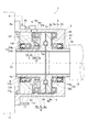
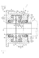
この発明を適用した回転体の作用力検出装置の概要を図1に示してある。この発明の実施形態における作用力検出装置1は、主要な構成要素として、ケース2、第1ロータ3、第2ロータ4、第1スラスト軸受5、第2スラスト軸受6、荷重変換機構7、検出部8、演算部9、および、出力部10を備えている。
An outline of a rotating body acting force detection apparatus to which the present invention is applied is shown in FIG. The acting
ケース2は、例えば円筒状に形成されており、内側の中空部分に、第1ロータ3や第2ロータ4などの作用力検出装置1の主要部を配置して収容する。そして、後述するように、第1ロータ3および第2ロータ4をそれぞれ回転自在に支持している。ケース2は、この発明の実施形態における支持部に相当する部材であり、所定の固定体に固定される。図1に示す例では、ケース2には、一方の端部(図1の左側の端部)に固定用のフランジ2aが形成されており、そのフランジ2aが、所定の機械装置における基体部(固定体)11に、回転不可能なように固定されている。また、ケース2の他方の端部(図1の右側の端部)には、カバー部2bが形成されている。カバー部2bは、ケース2の外形に応じた円板状に形成されてケース2の他方の端部を塞ぐと共に、その中心部分が、後述する第1ロータ3の先端(図1の右側の端部)の外形に合わせて開口している。
The
第1ロータ3は、所定の回転体に連結され、その回転体に一体となって回転する回転部材である。第1ロータ3は、円筒部3a、および、対向フランジ部3bを有している。円筒部3aは、第1ロータ3の円筒状に形成された部分であり、その外周部分に設けられたラジアル軸受12を介して、ケース2のカバー部2bに支持されている。例えば、ケース2におけるカバー部2bの内周部分に、ラジアル軸受12の外輪12aが圧入されている。ラジアル軸受12の内輪12bには、第1ロータ3における円筒部3aの外周部分が圧入されている。したがって、第1ロータ3は、ケース2に回転自在に支持されている。対向フランジ部3bは、円筒部3aの一方の端部(図1の左側の端部)に形成されたフランジ状の部材であり、後述する第2ロータ4の対向フランジ部4bに対向する対向面3cを有している。また、対向フランジ部3bは、後述する第2ロータ4の対向フランジ部4bおよびカムボール7cと共に、荷重変換機構7を構成している。図1に示す例では、第1ロータ3は、円筒部3aの他方の端部(図1の右側の端部)の内周面にスプラインまたはセレーションの溝が形成されており、その円筒部3aが、所定の機械装置における回転軸(回転体)13に一体となって回転するように締結されている。
The
第2ロータ4は、第1ロータ3と同一の回転軸線AL上で、第1ロータ3に対向して配置される回転部材である。第2ロータ4は、円筒部4a、および、対向フランジ部4bを有している。円筒部4aは、第2ロータ4の円筒状に形成された部分であり、その外周部分に設けられたラジアル軸受14および後述する荷重制限機構17の本体部17aを介して、ケース2に支持されている。すなわち、第2ロータ4は、第1ロータ3と共に、ケース2に回転自在に支持されている。第1ロータ3および第2ロータ4は、それぞれ、別個にケース2に支持されており、相対回転が可能なように配置されている。対向フランジ部4bは、円筒部4aの一方の端部(図1の右側の端部)に形成されたフランジ状の部材であり、第1ロータ3の対向フランジ部3bに対向する対向面4cを有している。また、対向フランジ部4bは、第1ロータ3の対向フランジ部3bおよび後述するカムボール7cと共に、荷重変換機構7を構成している。
The
第1スラスト軸受5は、第1ロータ3とケース2との間に配置されている。具体的には、第1ロータ3の対向フランジ部3bの背面3dと、ケース2のカバー部2bとの間に配置されている。なお、対向フランジ部3bの背面3dは、回転軸線AL方向における対向フランジ部3bの対向面3cと反対側(図1の右側)の面である。第1スラスト軸受5は、第1ロータ3に一体となって回転する軸軌道盤5aと、カバー部2bに当接して固定されるハウジング軌道盤5bとを有している。また、図1に示す例では、第1スラスト軸受5には、一般的なスラスト玉軸受が用いられており、軸軌道盤5aとハウジング軌道盤5bとの間で保持器(図示せず)によって保持された転動体5cを有している。そして、第1スラスト軸受5は、第1ロータ3に作用する回転軸線AL方向の推力またはその反力を受けて、第1ロータ3を回転自在に支持している。
The
第2スラスト軸受6は、第2ロータ4とケース2との間に配置されている。具体的には、第2ロータ4の対向フランジ部4bの背面4dと、後述する検出部8の起歪体15との間に配置されている。なお、対向フランジ部4bの背面4dは、回転軸線AL方向における対向フランジ部4bの対向面4cと反対側(図1の左側)の面である。第2スラスト軸受6は、第2ロータ4に一体となって回転する軸軌道盤6aと、後述する検出部8の起歪体15に当接して固定されるハウジング軌道盤6bとを有している。また、図1に示す例では、第2スラスト軸受6には、上記の第1スラスト軸受5と同様に、一般的なスラスト玉軸受が用いられており、軸軌道盤6aとハウジング軌道盤6bとの間で保持器(図示せず)によって保持された転動体6cを有している。そして、第2スラスト軸受6は、第2ロータ4に作用する回転軸線AL方向の推力またはその反力を受けて、第2ロータ4を回転自在に支持している。
The second thrust bearing 6 is disposed between the
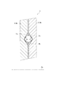
荷重変換機構7は、第1ロータ3と第2ロータ4との間に設けられている。そして、荷重変換機構7は、第1ロータ3および第2ロータ4に一体となって回転し、それら第1ロータ3と第2ロータ4との間でトルクを伝達する。それと共に、荷重変換機構7は、第1ロータ3と第2ロータ4との間のトルクの一部を回転軸線AL方向の推力に変換し、それら第1ロータ3と第2ロータ4との間で推力を伝達する。このように、荷重変換機構7は、回転運動を直線運動に変換する機構であり、例えば、ねじ機構、くさび機構、あるいは、カム機構などを利用して構成することができる。図1に示す例では、荷重変換機構7は、くさび機構およびカム機構の原理を応用した、いわゆるトルクカム機構によって構成されている。
The
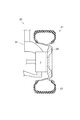
具体的には、図2に示すように、荷重変換機構7は、第1ロータ3に形成された第1カム面7a、第2ロータ4に形成された第2カム面7b、および、カムボール7cから構成されている。第1カム面7aは、第1ロータ3の対向フランジ部3bにおける対向面3cの、第2カム面7bと対向する位置に形成されている。第2カム面7bは、第2ロータ4の対向フランジ部4bにおける対向面4cの、第1カム面7aと対向する位置に形成されている。第1カム面7aおよび第2カム面7bは、いずれも、図2に示すように、第1ロータ3および第2ロータ4の径方向から見ると、断面がV字形状となるようにカム角度θで傾斜した2つの面により構成されている。そして、それら第1カム面7aと第2カム面7bとの間で、カムボール7cを転動可能に保持している。カムボール7cは、例えば玉軸受用の鋼球のような金属の剛体によって形成されている。
Specifically, as shown in FIG. 2, the
なお、図1では、所定の断面上の二箇所に荷重変換機構7が設けられた例を示しているが、それに限定されるものではなく、例えば四箇所もしくはそれ以上の箇所に荷重変換機構7を設けてもよい。この発明の実施形態における荷重変換機構7は、第1ロータ3の対向フランジ部3bおよび第2ロータ4の対向フランジ部4bの円周方向に、等ピッチで複数箇所(好ましくは、三箇所以上)に設けられる。
Although FIG. 1 shows an example in which the
このように、荷重変換機構7は、第1ロータ3と第2ロータ4との間で、トルクを推力に変換して伝達する。言い換えると、荷重変換機構7は、第1ロータ3のトルクと第2ロータ4のトルクとの差に応じた推力を発生させ、その発生させた推力を第1ロータ3と第2ロータ4との間で伝達する。図1に示す例では、第1ロータ3から第2ロータ4へ推力を伝達する。
As described above, the
上記のように荷重変換機構7を構成するトルクカム機構の基本的な構成や原理等に関しては、例えば、特許第4126986号公報、特開2010−215079号公報、あるいは、特開2011−80541号公報などに記載されているように周知であるため、より詳細な説明は省略する。
Regarding the basic configuration and principle of the torque cam mechanism that constitutes the
検出部8は、この発明の実施形態における支持部に設置されている。図1に示す例では、検出部8は、基体部11に固定されたケース2に設置されている。検出部8は、第1スラスト軸受5に作用する推力、または、第2スラスト軸受6に作用する推力の少なくともいずれかに関連する物理量を検出する。図1に示す例では、検出部8は、第2ロータ4から第2スラスト軸受6が受ける推力に関連する物理量を検出する。そして、検出部8は、起歪体15、および、センサー素子16を有している。
The
起歪体15は、一部がケース2に固定され、第2ロータ4から第2スラスト軸受6に作用する推力を受けることによって弾性変形する。図1に示す例では、起歪体15は、はり部15a、および、当接部15bから構成されている。
A part of the
はり部15aは、円環板状に形成されている。はり部15aは、その中心部分に、後述する荷重制限機構17の起歪体固定部17bに固定されるボス15cを有している。ボス15cの内周面には、後述する起歪体固定部17bに形成された雄ねじ部17eとはまり合う雌ねじ部15dが形成されている。そして、ボス15cは、後述するように、荷重制限機構17の起歪体固定部17bにねじ締結によって固定されている。荷重制限機構17は、後述する本体部17aでケース2に固定されている。はり部15aは、後述するように当接部15bに推力が作用する場合、起歪体15が弾性限界内で変形するように、所定の剛性を有する材料によって形成されている。
The
当接部15bは、はり部15aの外周側に形成されている。当接部15bは、第2スラスト軸受6のハウジング軌道盤6bと当接する(具体的には、密接する)当接面15eを有している。当接部15bは、上記のように当接面15eがハウジング軌道盤6bに密接しているのに対し、回転軸線AL方向における当接面15eと反対側(図1の左側)の背面15fは、いずれの部材とも接触することなく、後述する荷重制限機構17の対向面17cとの間に隙間GPが設けられている。また、当接部15bの外周部分は、例えばスプライン(図示せず)により、ケース2の内周部分にはめ込まれている。そのため、起歪体15は、回転軸線ALを回転中心とする回転が規制されつつ、当接部15bに第2スラスト軸受6から推力(第1ロータ3から第2ロータ4へ向かう推力)が作用した場合には、当接部15bの回転軸線AL方向への移動が可能になっている。
The
上記のはり部15aおよび当接部15bは一体に形成されている。そして、起歪体15は、はり部15aの一部(すなわち、ボス15c)で、ケース2に固定されている。したがって、起歪体15は、当接部15b側の端部(図1の上下方向におけるケース2側の端部)が自由端となり、はり部15a側の端部(図1の上下方向における回転軸線AL側の端部)を固定した片持ちばりと見なすことができる。起歪体15は、当接部15bで第2ロータ4から第2スラスト軸受6に作用する推力を受けることにより、はり部15aに曲げモーメントが作用し、はり部15aが弾性変形する。
The
センサー素子16は、起歪体15に取り付けられ、第2スラスト軸受6に作用する推力に関連する物理量として、起歪体15が上記のような推力を受けて弾性変形する際のひずみまたは変位を検出する。具体的には、センサー素子16は、起歪体15のはり部15aに装着され、はり部15aが曲げモーメントを受けて弾性変形する際のひずみまたは変位を検出する。図1に示す例では、センサー素子16としてひずみゲージが用いられており、はり部15aが弾性変形する際のひずみを検出する。ひずみゲージは、発生するひずみに応じて抵抗値が変化し、その抵抗値の変化分に比例した電圧(出力電圧)を出力する。なお、この発明の実施形態におけるセンサー素子16は、上記のようなひずみゲージ以外に、例えば、圧電素子や圧力センサーなどを用いることもできる。
The
いずれにしても、この発明の実施形態におけるセンサー素子16は、上記のように起歪体15が推力を受けて弾性変形する際のひずみまたは変位を検出し、その検出値を電気信号(例えば、ひずみゲージの出力電圧)として出力する。後述するように、センサー素子16から出力される電気信号、すなわち、センサー素子16の出力信号は、例えば、演算部9に入力され、演算部9で求めた作用力の出力信号として出力部10から外部に出力される。あるいは、出力部10から外部に出力され、外部に設けられた演算部9に入力される。その後、演算部9で求めた作用力の出力信号として外部に出力される。
In any case, the
この発明の実施形態における作用力検出装置1では、上述したケース2、第1ロータ3、第2ロータ4、第1スラスト軸受5、第2スラスト軸受6、荷重変換機構7、および、検出部8などの主要部に加え、荷重制限機構17、および、プレロード機構18を設けることが可能である。
In the acting
荷重制限機構17は、検出部8の起歪体15に作用する推力を制限するいわゆるストッパであり、検出部8の起歪体15に作用する推力の上限を規定する。図1に示す例では、荷重制限機構17は、ケース2の内側の中空部分に、回転軸線AL方向で起歪体15を挟み第2スラスト軸受6の反対側(図1の左側)に配置されている。荷重制限機構17は、本体部17a、および、起歪体固定部17bから構成されている。
The
本体部17aは、肉厚の円環板状に形成されている。本体部17aは、回転軸線AL方向への移動が不可能なように、ケース2に固定されている。本体部17aには、起歪体15の当接部15bにおける背面15fと対向する対向面17c、および、ラジアル軸受14を設置する軸受設置面17dが形成されている。
The
対向面17cは、本体部17aの一方の端部(図1の右側の端部)の外周部分に形成されている。対向面17cは、本体部17aをケース2に固定する際に、対向面17cの外周端部がケース2の内周面に形成された係止面2cに突き当てられる。それにより、対向面17cと起歪体15の背面15fとの間に、隙間GPが形成されている。隙間GPは、起歪体15が第2ロータ4および第2スラスト軸受6から推力を受ける際に、起歪体15が弾性限界を超えて変形することがないように、所定の間隔に設定されている。したがって、起歪体15が推力を受けて回転軸線AL方向に変位し、起歪体15の背面15fが対向面17cに当接した状態、すなわち、起歪体15が回転軸線AL方向で最大限に変形した状態であっても、起歪体15は弾性限界内にあり、塑性変形することはない。
The facing
軸受設置面17dは、本体部17aの内周面に形成されている。軸受設置面17dには、第2ロータ4を支持するためのラジアル軸受14が固定されている。例えば、軸受設置面17dに、ラジアル軸受14の外輪14aが圧入されている。ラジアル軸受14の内輪14bには、第2ロータ4における円筒部4aの外周部分が圧入されている。
The bearing
起歪体固定部17bは、本体部17aの一方の端部(図1の右側の端部)の内周部分に形成されている。起歪体固定部17bは、本体部17aの一方の端部から第2ロータ4の対向フランジ部4b側に向けて突出する円筒状に形成されている。起歪体固定部17bと本体部17aとは一体に形成されている。起歪体固定部17bの先端(図1の右側の端部)側の外周面には、雄ねじ部17eが形成されている。雄ねじ部17eは、前述した起歪体15のボス15cに形成された雌ねじ部15dとはまり合う。したがって、起歪体固定部17bは、雄ねじ部17eと起歪体15の雌ねじ部15dとのねじ締結作用により、起歪体15を固定する。すなわち、起歪体15は、はり部15aの一部(ボス15c)で、荷重制限機構17の起歪体固定部17bを介して、ケース2に固定されている。
The strain
なお、荷重制限機構17の本体部17aにおける他方の端部(図1の左側の端部)は、カバープレート17f、および、スナップリング17gにより、回転軸線AL方向の移動が規制されている。カバープレート17fは、ケース2の内周面の形状に応じた円板状に形成されている。カバープレート17fは、荷重制限機構17の本体部17aにおける他方の端部と当接した状態で、ケース2に取り付けられる。カバープレート17fの中心部分は、第2ロータ4の先端(図1の左側の端部)の外形に合わせて開口している。したがって、カバープレート17fは、例えばスナップリング17gによってケース2に固定されることにより、ケース2の開口側の端部(図1の左側の端部)を塞ぐと共に、荷重制限機構17のケース2からの抜け出しを防止している。
The other end (the left end in FIG. 1) of the
プレロード機構18は、検出部8の起歪体15に、プレロードとして推力を付与する機構である。この場合のプレロードとしての推力は、第2ロータ4から第2スラスト軸受6を介して起歪体15に作用する推力とは別の荷重である。プレロード機構18は、上述した起歪体15のボス15c、および、荷重制限機構17の起歪体固定部17bによって構成されている。具体的には、ボス15cに形成された雌ねじ部15d、および、起歪体固定部17bに形成された雄ねじ部17eによって構成されている。すなわち、プレロード機構18は、上記のような雌ねじ部15dと雄ねじ部17eとを有するいわゆる送りねじ機構によって構成されている。
The
したがって、雄ねじ部17eが形成された起歪体固定部17bおよび本体部17a(すなわち、荷重制限機構17)を回転軸線ALまわりに回転させることにより、起歪体固定部17bに対する起歪体15の固定位置を回転軸線AL方向に移動させることができる。起歪体固定部17bに対する起歪体15の固定位置を、回転軸線AL方向で第2ロータ4の対向フランジ部4b側(図1の右側)に移動させることにより、起歪体15に、回転軸線AL方向の推力(プレロード)を付与すること、あるいは、起歪体15に付与した回転軸線AL方向の推力を増大することができる。反対に、起歪体固定部17bに対する起歪体15の固定位置を、回転軸線AL方向で荷重制限機構17側(図1の左側)に移動させることにより、起歪体15に付与した回転軸線AL方向の推力を低減することができる。すなわち、プレロード機構18により、起歪体15にプレロードとして付与する推力の大きさを調整することができる。
Therefore, by rotating the strain
上記のように、プレロード機構18によって回転軸線AL方向の推力をプレロードとして起歪体15に付与することにより、その推力を起歪体15の当接部15bを介して第2スラスト軸受6に作用させることができる。すなわち、第2スラスト軸受6に、第2スラスト軸受6を第2ロータ4の対向フランジ部4b側(図1の右側)に押し付ける押圧力を作用させることができる。そのため、第2スラスト軸受6の回転軸線AL方向におけるがたを詰めることができる。また、プレロード機構18によって起歪体15にプレロードとして付与する推力を調整することにより、後述するように、検出部8の出力信号を基に演算部9で演算を実行する際の初期値あるいは原点を適宜設定することができる。
As described above, by applying the thrust in the rotational axis AL direction as a preload to the
演算部9は、例えばマイクロコンピュータを主体にして構成される演算装置であり、上述した検出部8の出力信号が入力される。演算部9は、入力された出力信号、および、予め記憶させられているデータや計算式等を使用して演算を行う。そして、演算部9は、その演算結果を、回転体に作用している作用力に応じた出力信号として出力する。具体的には、演算部9は、検出部8で検出する第1スラスト軸受5に作用する推力、または、第2スラスト軸受6に作用する推力の少なくともいずれかに関連する物理量に基づいて、第1ロータ3に連結される回転体に作用している作用力を求める。図1に示す例では、演算部9は、検出部8から入力されるセンサー素子16の出力信号、すなわち、ひずみゲージの出力電圧に基づいて、回転軸13に作用しているトルクを算出する。そして、算出したトルクの値に応じた出力信号(例えば、電圧などの電気信号)を出力する。
The
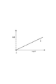
例えば、演算部9には、図3に示すような演算マップが記憶されている。図3に示す演算マップは、ひずみゲージの出力電圧に対応する回転軸13のトルクを定めた線図である。あるいは、演算部9には、図3の演算マップにおいて直線f0で表されるような演算式(図3に示す例では、一次方程式)が記憶されている。そして、演算部9は、図3に示すような演算マップ、あるいは、演算式を用いて、回転軸13に作用しているトルクを算出する。
For example, the
また、前述したように、この発明の実施形態における作用力検出装置1では、プレロード機構18によって検出部8の起歪体15に付与する推力を調整することにより、演算部9で演算を実行する際の初期値あるいは原点を設定することができる。したがって、例えば、検出部8の出力信号(ひずみゲージの出力電圧)の初期値を、上記の図3の演算マップにおいて点Oで示すような原点に一致させるように調整することが可能である。そのため、回転体の作用力(図1に示す例では、回転軸13のトルク)を、精度良く検出することができる。
Further, as described above, in the acting
出力部10は、この発明の実施形態における支持部に設置される。出力部10は、検出部8で検出する推力に関連する物理量に応じた出力信号を演算部9に出力する、または、演算部9で求める回転体の作用力に応じた出力信号を外部に出力する。図1に示す例では、出力部10は、上述した検出部8および演算部9と共に、ケース2に設置されており、演算部9で算出した回転軸13のトルクに応じた出力信号を外部に出力する。具体的には、出力部10は、出力端子や、出力ケーブルあるいはリード線の端部などをケース2に固定した部分である。出力部10は、例えば、この発明の実施形態における作用力検出装置1の外部に設けられている回転軸13の制御機器(図示せず)に、演算部9の出力信号を送ることが可能なように、ケーブルやリード線等を介して電気的に接続されている。検出部8と演算部9との間は、検出部8から出力される出力信号を演算部9で受け取ることが可能なように、ケーブルやリード線等を介して電気的に接続されている。また、演算部9と出力部10の間は、演算部9から出力される出力信号を出力部10で受け取ることが可能なように、ケーブルやリード線等を介して電気的に接続されている。
The
前述した特許文献1や特許文献2に記載された従来技術のように、無線通信によってセンサー素子の出力信号を取得する場合は、例えば電波や赤外線などの無線媒体を使用するため、ノイズの影響を受けやすく、そのための対策が必要になる。また、無線媒体の送信器および受信器を作動させるための電源を確保しなければならない。また、無線通信に替えてスリップリングを用いることも可能であるが、その場合は、不可避的に電極部分の摩耗や摩擦損失が発生してしまう。それに対して、この発明の実施形態における作用力検出装置1では、前述したような無線通信やスリップリングを用いることなく、検出部8で検出した出力信号、あるいは、演算部9で算出した出力信号を、容易に、かつ、適切に、外部に出力することができる。
As in the prior art described in
また、前述した特許文献3に記載された従来技術では、いわゆる6分力計を用いているため、相対的に装置が高価である。また、特許文献3に記載された従来技術は、一端が固定された感受体のねじれによる微小な相対変位あるいはひずみを検出するので、ひずみゲージの性能上の制約を受ける。そのため、高い検出精度を確保することは容易ではない。また、前述したように、感受体は、ホイールとハブユニットとの間で動力を伝達する強度部材となっている。そのため、感受体は、一定以上の強度および剛性が要求される。それに対して、この発明の実施形態における作用力検出装置1では、ひずみを発生させる起歪体15(後述する第1起歪体31および第2起歪体33も同様)は、前述したようないわゆる片持ちばりとして変形する部材として構成されており、動力を伝達する強度部材ではない。そのため、起歪体15は、相対的に低い剛性で構成することができ、弾性限界内で相対的に大きなひずみを発生させることが可能である。更に、この発明の実施形態における作用力検出装置1では、前述したような荷重制限機構17(後述する第1荷重制限機構25および第2荷重制限機構26も同様)が設けられることにより、起歪体15(ならびに、後述する第1起歪体31および第2起歪体33)の設計上の強度および剛性を低く抑えることができる。したがって、変形しやすい起歪体15(ならびに、後述する第1起歪体31および第2起歪体33)を設計することが可能である。そのため、センサー素子16(ならびに、後述する第1センサー素子32および第2センサー素子34)によって検出するひずみの検出レンジを幅広く取ることができ、その結果、回転軸13(および、後述するタイヤ23)に作用するトルクおよび推力の検出精度を向上することができる。
Moreover, in the prior art described in
なお、この発明の実施形態における演算部9は、図4に示すように、この作用力検出装置1の外部に設置されていてもよい。例えば、作用力検出装置1の外部に設けられている回転軸13の制御機器(図示せず)に、演算部9が組み込まれていてもよい。あるいは、作用力検出装置1の外部に設けられている回転軸13の制御機器や演算装置における演算機能を、この発明の実施形態における演算部9として機能させてもよい。その場合、検出部8と出力部10との間は、検出部8から出力される出力信号を出力部10で受け取ることが可能なように、ケーブルやリード線等を介して電気的に接続される。それと共に、出力部10と演算部9との間は、出力部10から出力される出力信号(すなわち、検出部8から出力された出力信号)を外部の演算部9で受け取ることが可能なように、ケーブルやリード線等を介して電気的に接続される。
In addition, the calculating
図5、図6に、この発明の実施形態における作用力検出装置1の他の構成例を示してある。なお、図5、図6に示す作用力検出装置1において、前述の図1で示した作用力検出装置1と構成や機能が同様の部品あるいは部材については、図1と同じ参照符号を付けてある。
5 and 6 show another configuration example of the acting
図5に示す作用力検出装置1は、第1ロータ3および第1スラスト軸受5の側に、検出部8が設置されている。すなわち、前述の図1に示した例では、検出部8が回転軸線AL方向における第2ロータ4および第2スラスト軸受6側(図1の左側)に設置されているのに対して、この図5に示す例では、検出部8は、回転軸線AL方向における第1ロータ3および第1スラスト軸受5側(図5の右側)に設置されている。第1ロータ3には、前述の図1で示した例と同様に、回転軸13が一体となって回転するように締結されている。
In the acting
したがって、この図5に示す例では、作用力検出装置1は、第1ロータ3と第2ロータ4との間で、荷重変換機構7によってトルクから変換される推力の反力を、第1ロータ3側に設置された検出部8で検出する。そして、その推力の反力を受けて検出部8の起歪体15が弾性変形する際に発生するひずみに基づいて、回転軸13に作用しているトルクを検出する。この図5に示す作用力検出装置1のように、第1ロータ3側に設置された検出部8で推力の反力に関連する物理量を検出する場合であっても、前述の図1で示した作用力検出装置1と同様に、回転軸13に作用するトルクを、容易に、かつ、精度良く検出することができる。なお、図5では、前述の図4で示した例と同様に、演算部9を作用力検出装置1の外部に設置した例を示してある。
Therefore, in the example shown in FIG. 5, the acting
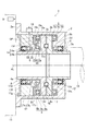
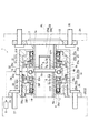
図6に示す作用力検出装置1は、図7に示すように、車両20の車輪21と車体(例えば、車両20のサスペンション)22との間に設けられ、車輪21に作用する作用力を検出する。車輪21は、タイヤ23、および、タイヤ23を装着するホイール24から構成されている。したがって、図6、図7に示す作用力検出装置1は、車両20のタイヤ23に作用するトルクおよび横力を検出する。また、図6に示す作用力検出装置1は、主要な構成要素として、ケース2、第1ロータ3、第2ロータ4、第1スラスト軸受5、第2スラスト軸受6、荷重変換機構7、検出部8、演算部9、出力部10、プレロード機構18、ならびに、第1荷重制限機構25、および、第2荷重制限機構26を備えている。なお、図6では、前述の図4で示した例と同様に、演算部9を作用力検出装置1の外部に設置した例を示してある。また、図7では、ブレーキ装置やサスペンション装置等を省略してある。
As shown in FIG. 7, the acting
図6に示す例では、ケース2には、一方の端部(図6の左側の端部)に固定用のフランジ2aが形成されている。フランジ2aには、本体固定用のボルト穴(図示せず)が複数形成されており、本体固定用のボルト27により、フランジ2aと車両20の車体22とがボルト締結されている。したがって、ケース2は、車体(固定体)22に、回転不可能なように固定されている。
In the example shown in FIG. 6, the
第1ロータ3には、車輪21のホイール24が一体となって回転するように締結されている。具体的には、第1ロータ3の一方の端部(図6の右側の端部)に、フランジ28が取り付けられている。例えば、第1ロータ3の円筒部3aの内周面、および、フランジ28のボス28aの外周面には、セレーションが形成されており、第1ロータ3の円筒部3aにフランジ28のボス28aが圧入されている。ボス28aの先端(図6の左側の端部)には、ねじ穴28bが形成されている。そのねじ穴28bに、第1ロータ3の他方の端部(図6の左側の端部)からボルト29が締め込まれることにより、第1ロータ3とフランジ28とが一体に締結されている。すなわち、ボルト29は、ねじ締結によってフランジ28のボス28aに固定されることにより、フランジ28の第1ロータ3からの抜け出しを防止している。
The
フランジ28には、ホイール24に形成されたホイール固定用のボルト穴と対応する位置に、ホイール固定用の複数のボルト30が取り付けられており、フランジ28とホイール24とがボルト締結されている。したがって、第1ロータ3とホイール24とが、互いに一体となって回転する。なお、第2ロータ4には、車両20のドライブシャフト(図示せず)が一体となって回転するように締結されている。
A plurality of
この図6に示す作用力検出装置1は、第1ロータ3および第1スラスト軸受5側、および、第2ロータ4および第2スラスト軸受6側の両方に、検出部8が設置されている。そして、検出部8は、第1スラスト軸受5に作用する推力に関連する物理量、および、第2スラスト軸受6に作用する推力に関連する物理量を検出する。
In the acting
図6に示す例では、検出部8は、車体22に固定されたケース2に設置されている。検出部8は、第1ロータ3側に設置される第1起歪体31、および、第1センサー素子32、ならびに、第2ロータ4側に設置される第2起歪体33、および、第2センサー素子34を有している。そして、検出部8は、第1ロータ3から第1スラスト軸受5が受ける推力に関連する物理量、および、第2ロータ4から第2スラスト軸受6が受ける推力に関連する物理量を検出する。
In the example shown in FIG. 6, the
第1起歪体31は、一部がケース2に固定され、第1ロータ3から第1スラスト軸受5に作用する推力(または、推力の反力)を受けることによって弾性変形する。図6に示す例では、第1起歪体31は、はり部31a、および、当接部31bから構成されている。
A part of the
はり部31aは、円環板状に形成されている。はり部31aは、その外周部分に、ケース2に固定されるボス31cを有している。ボス31cは、例えばねじ締結や圧入により、ケース2の内周部分に固定されている。すなわち、第1起歪体31は、はり部31aの一部(ボス31c)で、ケース2に固定されている。はり部31aは、後述するように当接部31bに推力が作用する場合、第1起歪体31が弾性限界内で変形するように、所定の剛性を有する材料によって形成されている。
The
当接部31bは、はり部31aの内周側に形成されている。当接部31bは、第1スラスト軸受5のハウジング軌道盤5bと当接する(具体的には、密接する)当接面31eを有している。当接部31bは、上記のように当接面31eがハウジング軌道盤6bに密接しているのに対し、回転軸線AL方向における当接面31eと反対側(図6の右側)の背面31fは、いずれの部材とも接触することなく、後述する第1荷重制限機構25の対向面25cとの間に隙間GP1が設けられている。また、当接部31bの内周部分は、例えばスプライン(図示せず)により、第1ロータ3における円筒部3aの外周部分にはめ込まれている。そのため、第1起歪体31は、回転軸線ALを回転中心とする回転が規制されつつ、当接部31bに第1スラスト軸受5から推力(第1ロータ3から第2ロータ4へ向かう推力の反力)が作用した場合には、当接部31bの回転軸線AL方向への移動が可能になっている。
The contact part 31b is formed on the inner peripheral side of the
上記のはり部31aおよび当接部31bは一体に形成されている。そして、第1起歪体31は、はり部31aの一部(すなわち、ボス31c)で、ケース2に固定されている。したがって、第1起歪体31は、当接部31b側の端部(図6の上下方向における回転軸線AL側の端部)が自由端となり、はり部31a側の端部(図6の上下方向におけるケース2側の端部)を固定した片持ちばりと見なすことができる。第1起歪体31は、当接部31bで第1ロータ3から第1スラスト軸受5に作用する推力(または、推力の反力)を受けることにより、はり部31aに曲げモーメントが作用し、はり部31aが弾性変形する。
The
第1センサー素子32は、第1起歪体31に取り付けられ、第1スラスト軸受5に作用する推力に関連する物理量として、第1起歪体31が上記のような推力を受けて弾性変形する際のひずみまたは変位を検出する。具体的には、第1センサー素子32は、第1起歪体31のはり部31aに装着され、はり部31aが曲げモーメントを受けて弾性変形する際のひずみまたは変位を検出する。図6に示す例では、第1センサー素子32としてひずみゲージが用いられており、はり部31aが弾性変形する際のひずみを検出する。ひずみゲージは、発生するひずみに応じて抵抗値が変化し、その抵抗値の変化分に比例した電圧(出力電圧)を出力する。なお、この発明の実施形態における第1センサー素子32は、上記のようなひずみゲージ以外に、例えば、圧電素子や圧力センサーなどを用いることもできる。
The
第2起歪体33は、一部がケース2に固定され、第2ロータ4から第2スラスト軸受6に作用する推力を受けることによって弾性変形する。図6に示す例では、第2起歪体33は、はり部33a、および、当接部33bから構成されている。
A part of the
はり部33aは、円環板状に形成されている。はり部33aは、その外周部分に、後述する第2荷重制限機構26の起歪体固定部26bに固定されるボス33cを有している。ボス33cの外周面には、後述する起歪体固定部26bに形成された雌ねじ部26eとはまり合う雄ねじ部33dが形成されている。そして、ボス33cは、後述するように、第2荷重制限機構26の起歪体固定部26bにねじ締結によって固定されている。第2荷重制限機構26は、後述する本体部26aでケース2に固定されている。はり部33aは、後述するように当接部33bに推力が作用する場合、第2起歪体33が弾性限界内で変形するように、所定の剛性を有する材料によって形成されている。
The
当接部33bは、はり部33aの内周側に形成されている。当接部33bは、第2スラスト軸受6のハウジング軌道盤6bと当接する(具体的には、密接する)当接面33eを有している。当接部33bは、上記のように当接面33eがハウジング軌道盤6bに密接しているのに対し、回転軸線AL方向における当接面33eと反対側(図6の左側)の背面33fは、いずれの部材とも接触することなく、後述する第2荷重制限機構26の対向面26cとの間に隙間GP2が設けられている。また、当接部33bの内周部分は、例えばスプライン(図示せず)により、第2ロータ4における円筒部4aの外周部分にはめ込まれている。そのため、第2起歪体33は、回転軸線ALを回転中心とする回転が規制されつつ、当接部33bに第2スラスト軸受6から推力(第1ロータ3から第2ロータ4へ向かう推力)が作用した場合には、当接部33bの回転軸線AL方向への移動が可能になっている。
The
上記のはり部33aおよび当接部33bは一体に形成されている。そして、第2起歪体33は、はり部33aの一部(すなわち、ボス33c)で、ケース2に固定されている。したがって、第2起歪体33は、当接部33b側の端部(図6の上下方向における回転軸線AL側の端部)が自由端となり、はり部33a側の端部(図6の上下方向におけるケース2側の端部)を固定した片持ちばりと見なすことができる。第2起歪体33は、当接部33bで第2ロータ4から第2スラスト軸受6に作用する推力を受けることにより、はり部33aに曲げモーメントが作用し、はり部33aが弾性変形する。
The
第2センサー素子34は、第2起歪体33に取り付けられ、第2スラスト軸受6に作用する推力に関連する物理量として、第2起歪体33が上記のような推力を受けて弾性変形する際のひずみまたは変位を検出する。具体的には、第2センサー素子34は、第2起歪体33のはり部33aに装着され、はり部33aが曲げモーメントを受けて弾性変形する際のひずみまたは変位を検出する。図6に示す例では、第2センサー素子34としてひずみゲージが用いられており、はり部33aが弾性変形する際のひずみを検出する。ひずみゲージは、発生するひずみに応じて抵抗値が変化し、その抵抗値の変化分に比例した電圧(出力電圧)を出力する。なお、この発明の実施形態における第2センサー素子34は、上記のようなひずみゲージ以外に、例えば、圧電素子や圧力センサーなどを用いることもできる。
The
第1荷重制限機構25は、検出部8の第1起歪体31に作用する推力を制限するいわゆるストッパであり、検出部8の第1起歪体31に作用する推力の上限を規定する。図6に示す例では、第1荷重制限機構25は、ケース2の内側の中空部分に、回転軸線AL方向で第1起歪体31を挟み第1スラスト軸受5の反対側(図1の右側)に配置されている。第1荷重制限機構25は、本体部25a、および、起歪体固定部25bから構成されている。
The first
本体部25aは、肉厚の円環板状に形成されている。本体部25aは、回転軸線AL方向への移動が不可能なように、ケース2に固定されている。本体部25aには、第1起歪体31の当接部31bにおける背面31fと対向する対向面25c、および、ラジアル軸受14を設置する軸受設置面25dが形成されている。
The
対向面25cは、本体部25aの一方の端部(図1の左側の端部)の外周部分に形成されている。対向面25cは、本体部25aおよび第1起歪体31をケース2に固定した状態で、第1起歪体31の背面31fに対向する。その状態で、対向面25cと背面31fとの間に、隙間GP1が形成されている。隙間GP1は、第1起歪体31が第1ロータ3および第1スラスト軸受5から推力を受ける際に、第1起歪体31が弾性限界を超えて変形することがないように、所定の間隔に設定されている。したがって、第1起歪体31が推力を受けて回転軸線AL方向に変位し、第1起歪体31の背面31fが対向面25cに当接した状態、すなわち、第1起歪体31が回転軸線AL方向で最大限に変形した状態であっても、第1起歪体31は弾性限界内にあり、塑性変形することはない。
The facing
軸受設置面25dは、本体部25aの内周面に形成されている。軸受設置面25dには、第1ロータ3を支持するためのラジアル軸受12が固定されている。例えば、軸受設置面25dに、ラジアル軸受12の外輪12aが圧入されている。ラジアル軸受12の内輪12bには、第1ロータ3における円筒部3aの外周部分が圧入されている。
The bearing
起歪体固定部25bは、本体部25aの一方の端部(図1の左側の端部)の外周部分に形成されている。起歪体固定部25bは、本体部25aの一方の端部から第1ロータ3の対向フランジ部3b側に向けて突出する円筒状に形成されている。起歪体固定部25bと本体部25aとは一体に形成されている。
The strain
第2荷重制限機構26は、検出部8の第2起歪体33に作用する推力を制限するいわゆるストッパであり、第2起歪体33に作用する推力の上限を規定する。図6に示す例では、第2荷重制限機構26は、ケース2の内側の中空部分に、回転軸線AL方向で第2起歪体33を挟み第2スラスト軸受6の反対側(図6の左側)に配置されている。第2荷重制限機構26は、本体部26a、および、起歪体固定部26bから構成されている。
The second
本体部26aは、肉厚の円環板状に形成されている。本体部26aは、回転軸線AL方向への移動が不可能なように、ケース2に固定されている。本体部26aには、第2起歪体33の当接部33bにおける背面33fと対向する対向面26c、および、ラジアル軸受14を設置する軸受設置面26dが形成されている。
The
対向面26cは、本体部26aの一方の端部(図6の右側の端部)の内周部分に形成されている。対向面26cは、本体部26aおよび第2起歪体33をケース2に固定した状態で、第2起歪体33の背面33fに対向する。その状態で、対向面26cと背面33fとの間に、隙間GP2が形成されている。隙間GP1は、第2起歪体33が第2ロータ4および第2スラスト軸受6から推力を受ける際に、第2起歪体33が弾性限界を超えて変形することがないように、所定の間隔に設定されている。したがって、第2起歪体33が推力を受けて回転軸線AL方向に変位し、第2起歪体33の背面33fが対向面26cに当接した状態、すなわち、第2起歪体33が回転軸線AL方向で最大限に変形した状態であっても、第2起歪体33は弾性限界内にあり、塑性変形することはない。
The facing
軸受設置面26dは、本体部26aの内周面に形成されている。軸受設置面26dには、第2ロータ4を支持するためのラジアル軸受14が固定されている。例えば、軸受設置面26dに、ラジアル軸受14の外輪14aが圧入されている。ラジアル軸受14の内輪14bには、第2ロータ4における円筒部4aの外周部分が圧入されている。
26 d of bearing installation surfaces are formed in the internal peripheral surface of the main-
起歪体固定部26bは、本体部26aの一方の端部(図6の右側の端部)の外周部分に形成されている。起歪体固定部26bは、本体部26aの一方の端部から第2ロータ4の対向フランジ部4b側に向けて突出する円筒状に形成されている。起歪体固定部26bと本体部26aとは一体に形成されている。起歪体固定部26bの先端(図6の右側の端部)側の内周面には、雌ねじ部26eが形成されている。雌ねじ部26eは、前述した第2起歪体33のボス33cに形成された雄ねじ部33dとはまり合う。したがって、起歪体固定部26bは、雌ねじ部26eと第2起歪体33の雄ねじ部33dとのねじ締結作用により、第2起歪体33を固定する。すなわち、第2起歪体33は、はり部33aの一部(ボス33c)で、第2荷重制限機構26の起歪体固定部26bを介して、ケース2に固定されている。
The strain
なお、第2荷重制限機構26の本体部26aにおける他方の端部(図6の左側の端部)は、固定リング26fにより、回転軸線AL方向の移動が規制されている。固定リング26fは、円筒状に形成されており、その円筒部分の一方の端部(図6の右側の端部)の外周面に、ケース2の内周面に形成された雌ねじ(図示せず)とはまり合う雄ねじ(図示せず)が形成されている。固定リング26fの他方の端部(図6の左側の端部)には、ケース2に係合するフランジ26gが形成されている。したがって、固定リング26fは、ねじ締結によってケース2に固定されることにより、第2荷重制限機構26のケース2からの抜け出しを防止している。
The other end (the left end in FIG. 6) of the
なお、この図6に示す例では、プレロード機構18は、検出部8の第2起歪体33に、プレロードとして推力を付与する機構である。この場合のプレロードとしての推力は、第2ロータ4から第2スラスト軸受6を介して第2起歪体33に作用する推力とは別の荷重である。図6に示す例では、プレロード機構18は、上述した第2起歪体33のボス33c、および、第2荷重制限機構26の起歪体固定部26bによって構成されている。具体的には、ボス33cに形成された雄ねじ部33d、および、起歪体固定部26bに形成された雌ねじ部26eによって構成されている。すなわち、プレロード機構18は、上記のような雌ねじ部26eと雄ねじ部33dとを有するいわゆる送りねじ機構によって構成されている。
In the example shown in FIG. 6, the
したがって、雌ねじ部26eが形成された起歪体固定部26bおよび本体部26a(すなわち、第2荷重制限機構26)を回転軸線ALまわりに回転させることにより、起歪体固定部26bに対する第2起歪体33の固定位置を回転軸線AL方向に移動させることができる。起歪体固定部26bに対する第2起歪体33の固定位置を、回転軸線AL方向で第2ロータ4の対向フランジ部4b側(図6の右側)に移動させることにより、第2起歪体33に、回転軸線AL方向の推力(プレロード)を付与すること、あるいは、第2起歪体33に付与した回転軸線AL方向の推力を増大することができる。反対に、起歪体固定部26bに対する第2起歪体33の固定位置を、回転軸線AL方向で第2荷重制限機構26側(図6の左側)に移動させることにより、第2起歪体33に付与した回転軸線AL方向の推力を低減することができる。すなわち、プレロード機構18により、第2起歪体33にプレロードとして付与する推力の大きさを調整することができる。
Accordingly, the strain generating
上記のように、プレロード機構18によって回転軸線AL方向の推力をプレロードとして第2起歪体33に付与することにより、その推力を第2起歪体33の当接部33bを介して第2スラスト軸受6に作用させることができる。すなわち、第2スラスト軸受6に、第2スラスト軸受6を第2ロータ4の対向フランジ部4b側(図6の右側)に押し付ける押圧力を作用させることができる。そのため、第2スラスト軸受6の回転軸線AL方向におけるがたを詰めることができる。また、プレロード機構18によって第2起歪体33にプレロードとして付与する推力を調整することにより、検出部8の出力信号を基に演算部9で演算を実行する際の初期値あるいは原点を適宜設定することができる。
As described above, the thrust in the direction of the rotation axis AL is applied to the
この図6に示す作用力検出装置1では、演算部9には、例えば図8に示すような演算マップが記憶されている。図8に示す演算マップは、ひずみゲージの出力電圧に基づいてタイヤ23の横力およびトルクを求めるための線図である。あるいは、演算部9には、図8の演算マップにおいて直線f1および直線f2で表されるような演算式が記憶されている。そして、図6に示す作用力検出装置1では、演算部9は、図8に示すような演算マップ、あるいは、演算式を用いて、タイヤ23に作用している横力およびトルクを算出する。
In the acting
例えば、図8に示す演算マップの直線f1において、第1センサー素子32の出力電圧をF1、図8に示す演算マップの直線f2において、第2センサー素子34の出力電圧をF2、そして、図8に示す演算マップの点P、すなわち、直線f1および直線f2の原点の値をFkとすると、タイヤ23に作用している横力Flは、
Fl=F2−F1 ・・・・・(1)
の演算式に基づいて算出される。また、タイヤ23に作用しているトルクFtは、
Ft=(F2−Fk)+(F1−Fk)
すなわち、
Ft=F2+F1 ・・・・・(2)
の演算式に基づいて算出される。
For example, on the straight line f1 of the calculation map shown in FIG. 8, the output voltage of the
Fl = F2-F1 (1)
It is calculated based on the arithmetic expression. Further, the torque Ft acting on the
Ft = (F2-Fk) + (F1-Fk)
That is,
Ft = F2 + F1 (2)
It is calculated based on the arithmetic expression.
また、この図6に示す作用力検出装置1は、前述したように、プレロード機構18によって検出部8の第2起歪体33に付与する推力を調整することにより、演算部9で演算を実行する際の初期値あるいは原点を設定することができる。したがって、例えば、検出部8の出力信号(ひずみゲージの出力電圧)の初期値を、上記の図8の演算マップにおいて点Pで示すような原点に一致させるように調整することが可能である。そのため、タイヤ23の作用力(図6,図8で示す例では、タイヤ23の横力およびトルク)を精度良く検出することができる。
In addition, as described above, the acting
また、この図6に示す作用力検出装置1では、第1ロータ3側および第2ロータ4側の両方に、検出部8(すなわち、第1起歪体31および第1センサー素子32、ならびに、第2起歪体33および第2センサー素子34)が設けられている。そして、それら第1センサー素子32および第2センサー素子34の両方の検出値に基づいて、タイヤ23に作用するトルクおよび横力が求められる。上記の図8で示す例から分かるように、実際にタイヤ23に作用している横力が0の場合は、上記の(1)式から「F1=F2」となり、その場合のタイヤ23のトルクは、上記の(2)式から「F1×2」または「F2×2」となる。そのため、第1センサー素子32と第2センサー素子34との間に、冗長性を持たせることができる。すなわち、仮に、第1センサー素子32または第2センサー素子34のいずれか一方にフェールが生じた場合であっても、タイヤ23のトルクを検出することができる。したがって、作用力検出装置1の信頼性を高めることができる。
Further, in the acting
なお、この発明の実施形態においては、前述の図1、図4、図5で示したような作用力検出装置1を、図7に示すように車両20の車体22と車輪21のホイール24との間に設けてもよい。すなわち、この発明に実施形態における作用力検出装置1は、第1ロータ3側または第2ロータ4側のいずれか一方のみに検出部8(起歪体15およびセンサー素子16)を設けた作用力検出装置1を車両20に搭載し、タイヤ23に作用するトルクを検出するように構成することもできる。
In the embodiment of the present invention, the acting
1…回転体の作用力検出装置、 2…ケース(支持部)、 2a…フランジ、 2b…カバー部、 2c…係止面、 3…第1ロータ、 3a…円筒部、 3b…対向フランジ部、 3c…対向面、 3d…背面、 4…第2ロータ、 4a…円筒部、 4b…対向フランジ部、 4c…対向面、 4d…背面、 5…第1スラスト軸受、 5a…軸軌道盤、 5b…ハウジング軌道盤、 5c…転動体、 6…第2スラスト軸受、 6a…軸軌道盤、 6b…ハウジング軌道盤、 6c…転動体、 7…荷重変換機構、 7a…第1カム面、 7b…第2カム面、 7c…カムボール、 8…検出部、 9…演算部、 10…出力部、 11…基体部(固定体)、 12,14…ラジアル軸受、 12a,14a…外輪、 12b,14b…内輪、 13…回転軸(回転体)、 15…起歪体、 15a…はり部、 15b…当接部、 15c…ボス、 15d…雌ねじ部、 15e…当接面、 15f…背面、 16…センサー素子(ひずみゲージ)、 17…荷重制限機構、 17a…本体部、 17b…起歪体固定部、 17c…対向面、 17d…軸受設置面、 17e…雄ねじ部、 17f…カバープレート、 17g…スナップリング、 18…プレロード機構、 20…車両、21…車輪(回転体)、 22…車体(固定体)、 23…タイヤ(回転体)、 24…ホイール(回転体)、 25…第1荷重制限機構、 25a…本体部、 25b…起歪体固定部、 25c…対向面、 25d…軸受設置面、 26…第2荷重制限機構、 26a…本体部、 26b…起歪体固定部、 26c…対向面、 26d…軸受設置面、 26e…雌ねじ部、 26f…固定リング、 26g…フランジ、 27,29,30…ボルト、 28…フランジ、 28a…ボス、 28b…ねじ穴 、 31……第1起歪体、 31a…はり部、 31b…当接部、 31c…ボス、 32…第1センサー素子(ひずみゲージ)、33…第2起歪体、 33a…はり部、 33b…当接部、 33c…ボス、 33d…雄ねじ部、 33e…当接面、 33f…背面、 34…第2センサー素子(ひずみゲージ)、 AL…回転軸線、 GP,GP1,GP2…隙間。
DESCRIPTION OF
Claims (9)
前記回転体に連結され、前記回転体に一体となって回転する第1ロータと、
前記回転体および前記第1ロータと同一の回転軸線上で、前記第1ロータに対向し、かつ、前記第1ロータと相対回転可能に配置された第2ロータと、
前記第1ロータおよび前記第2ロータをそれぞれ回転自在に支持すると共に、前記固定体に固定される支持部と、
前記第1ロータと前記支持部との間で、前記第1ロータに作用する前記回転軸線方向の推力を受けて前記第1ロータを支持する第1スラスト軸受と、
前記第2ロータと前記支持部との間で、前記第2ロータに作用する前記回転軸線方向の推力を受けて前記第2ロータを支持する第2スラスト軸受と、
前記第1ロータと前記第2ロータとの間に配置され、前記第1ロータおよび前記第2ロータに一体となって回転して前記第1ロータと前記第2ロータとの間でトルクを伝達すると共に、前記トルクの一部を前記推力に変換して前記第1ロータと前記第2ロータとの間で前記推力を伝達する荷重変換機構と、
一部が前記支持部に固定され、前記第1スラスト軸受に作用する前記推力、または、前記第2スラスト軸受に作用する前記推力の少なくともいずれかの前記推力を受けることにより変形する起歪体、および、前記起歪体に取り付けられ、前記起歪体が前記変形する際の前記推力に関連する物理量を検出するセンサー素子を有する検出部と、
前記検出部で検出した前記物理量に基づいて、前記回転体に作用している前記作用力を求める演算部と、
前記支持部に設置され、前記検出部で検出する前記物理量に応じた出力信号を前記演算部に出力する、または、前記演算部で求める前記作用力に応じた出力信号を外部に出力する出力部とを備えている
ことを特徴とする回転体の作用力検出装置。
In an acting force detection device for a rotating body that is provided between a predetermined rotating body and a predetermined fixed body that rotatably supports the rotating body and detects an acting force acting on the rotating body,
A first rotor coupled to the rotating body and rotating integrally with the rotating body;
A second rotor disposed on the same rotational axis as the rotating body and the first rotor so as to face the first rotor and to be rotatable relative to the first rotor;
A support portion that rotatably supports the first rotor and the second rotor, and is fixed to the fixed body;
A first thrust bearing that supports the first rotor by receiving a thrust in the direction of the rotation axis acting on the first rotor between the first rotor and the support;
A second thrust bearing for supporting the second rotor by receiving a thrust in the rotational axis direction acting on the second rotor between the second rotor and the support portion;
The first rotor and the second rotor are disposed between the first rotor and the second rotor, and rotate integrally with the first rotor and the second rotor to transmit torque between the first rotor and the second rotor. And a load conversion mechanism for converting a part of the torque into the thrust and transmitting the thrust between the first rotor and the second rotor;
A strain-generating body, a part of which is fixed to the support, and deforms by receiving at least one of the thrust acting on the first thrust bearing or the thrust acting on the second thrust bearing, And a detection unit having a sensor element that is attached to the strain body and that detects a physical quantity related to the thrust when the strain body deforms,
Based on the physical quantity detected by the detection unit, a calculation unit for obtaining the acting force acting on the rotating body;
An output unit that is installed in the support unit and outputs an output signal corresponding to the physical quantity detected by the detection unit to the calculation unit, or outputs an output signal corresponding to the acting force obtained by the calculation unit to the outside An apparatus for detecting an acting force of a rotating body.
前記起歪体は、前記第2ロータから前記第2スラスト軸受に作用する前記推力を受けることにより弾性変形し、
前記センサー素子は、前記起歪体が前記弾性変形する際のひずみまたは変位を検出し、
前記第2スラスト軸受は、前記第2ロータに一体となって回転する軸軌道盤と、前記起歪体に当接するハウジング軌道盤とを有し、
前記センサー素子は、前記演算部および前記出力部と電気的に接続され、
前記演算部は、前記センサー素子で検出した前記ひずみまたは前記変位に基づいて、前記回転体に作用しているトルクを求める
ことを特徴とする回転体の作用力検出装置。
In the rotating body acting force detection apparatus according to claim 1,
The strain body is elastically deformed by receiving the thrust acting on the second thrust bearing from the second rotor,
The sensor element detects strain or displacement when the strain body elastically deforms,
The second thrust bearing has a shaft washer that rotates integrally with the second rotor, and a housing washer that contacts the strain body,
The sensor element is electrically connected to the calculation unit and the output unit,
The said calculating part calculates | requires the torque which is acting on the said rotating body based on the said distortion or the said displacement detected by the said sensor element, The acting force detection apparatus of the rotating body characterized by the above-mentioned.
前記起歪体は、一部が前記支持部に固定され、前記第1ロータから前記第1スラスト軸受に作用する前記推力を受けることにより弾性変形する第1起歪体と、一部が前記支持部に固定され、前記第2ロータから前記第2スラスト軸受に作用する前記推力を受けることにより弾性変形する第2起歪体とを有し、
前記センサー素子は、前記第1起歪体に取り付けられ、前記第1起歪体が前記弾性変形する際のひずみまたは変位を検出する第1センサー素子と、前記第2起歪体に取り付けられ、前記第2起歪体が前記弾性変形する際のひずみまたは変位を検出する第2センサー素子とを有し、
前記第1スラスト軸受は、前記第1ロータに一体となって回転する第1軸軌道盤と、前記第1起歪体に当接する第1ハウジング軌道盤とを有し、
前記第2スラスト軸受は、前記第2ロータに一体となって回転する第2軸軌道盤と、前記第2起歪体に当接する第2ハウジング軌道盤とを有し、
前記第1センサー素子および前記第2センサー素子は、それぞれ、前記演算部および前記出力部と電気的に接続され、
前記演算部は、前記第1センサー素子および前記第2センサー素子で検出した前記ひずみまたは前記変位に基づいて、前記回転体に作用しているトルクおよび前記推力の少なくともいずれかを求める
ことを特徴とする回転体の作用力検出装置。
In the rotating body acting force detection apparatus according to claim 1,
The first strain body is elastically deformed by receiving a thrust acting on the first thrust bearing from the first rotor, and a part of the first strain body is fixed to the support portion. And a second strain body that is elastically deformed by receiving the thrust acting on the second thrust bearing from the second rotor,
The sensor element is attached to the first strain body, and is attached to the first sensor element that detects strain or displacement when the first strain body elastically deforms, and the second strain body, A second sensor element that detects strain or displacement when the second strain body elastically deforms;
The first thrust bearing includes a first shaft washer that rotates integrally with the first rotor, and a first housing washer that contacts the first strain body,
The second thrust bearing has a second shaft washer that rotates integrally with the second rotor, and a second housing washer that contacts the second strain body,
The first sensor element and the second sensor element are electrically connected to the calculation unit and the output unit, respectively.
The calculation unit obtains at least one of a torque acting on the rotating body and the thrust based on the strain or the displacement detected by the first sensor element and the second sensor element. Rotating body acting force detection device.
前記起歪体に作用する前記推力の上限を規定する荷重制限機構を更に備えている
ことを特徴とする回転体の作用力検出装置。
The apparatus for detecting an acting force of a rotating body according to claim 2,
An apparatus for detecting an acting force of a rotating body, further comprising a load limiting mechanism for defining an upper limit of the thrust acting on the strain generating body.
前記第1起歪体に作用する前記推力の上限を規定する第1荷重制限機構と、
前記第2起歪体に作用する前記推力の上限を規定する第2荷重制限機構とを更に備えている
ことを特徴とする回転体の作用力検出装置。
The acting force detection apparatus for a rotating body according to claim 3,
A first load limiting mechanism that defines an upper limit of the thrust acting on the first strain body;
An apparatus for detecting an acting force of a rotating body, further comprising: a second load limiting mechanism that defines an upper limit of the thrust acting on the second strain generating body.
前記起歪体に、予め前記推力を付与するプレロード機構を更に備えている
ことを特徴とする回転体の作用力検出装置。
The apparatus for detecting an acting force of a rotating body according to claim 2 or 4,
An apparatus for detecting an acting force of a rotating body, further comprising a preload mechanism that applies the thrust in advance to the strain generating body.
前記第2起歪体に、予め前記推力を付与するプレロード機構とを更に備えている
ことを特徴とする回転体の作用力検出装置。
In the rotating body acting force detection apparatus according to claim 3 or 5,
An apparatus for detecting an acting force of a rotating body, further comprising: a preload mechanism that applies the thrust to the second strain body in advance.
前記第1ロータは、車両のタイヤを装着したホイールに連結され、
前記支持部は、前記車両の車体に固定され、
前記演算部は、前記センサー素子で検出した前記ひずみまたは前記変位に基づいて、前記タイヤに作用しているトルクを求める
ことを特徴とする回転体の作用力検出装置。
In the rotating body acting force detection device according to any one of claims 2, 4, and 6,
The first rotor is connected to a wheel fitted with a vehicle tire;
The support portion is fixed to a vehicle body of the vehicle,
The said calculating part calculates | requires the torque which is acting on the said tire based on the said distortion or the said displacement detected with the said sensor element, The acting force detection apparatus of the rotary body characterized by the above-mentioned.
前記第1ロータは、車両のタイヤを装着したホイールに連結され、
前記支持部は、前記車両の車体に固定され、
前記演算部は、前記第1センサー素子および前記第2センサー素子で検出した前記ひずみまたは前記変位に基づいて、前記タイヤに作用しているトルクおよび横力の少なくともいずれかを求める
ことを特徴とする回転体の作用力検出装置。 In the acting force detection apparatus of the rotary body according to any one of claims 3, 5, and 7,
The first rotor is connected to a wheel fitted with a vehicle tire;
The support portion is fixed to a vehicle body of the vehicle,
The calculation unit obtains at least one of a torque and a lateral force acting on the tire based on the strain or the displacement detected by the first sensor element and the second sensor element. Rotating body acting force detection device.
Priority Applications (4)
| Application Number | Priority Date | Filing Date | Title |
|---|---|---|---|
| JP2018080453A JP6907993B2 (en) | 2018-04-19 | 2018-04-19 | Acting force detector for rotating body |
| DE102019109347.3A DE102019109347A1 (en) | 2018-04-19 | 2019-04-09 | Wind force detection unit for rotation element |
| US16/386,749 US10983021B2 (en) | 2018-04-19 | 2019-04-17 | Action force detecting unit for rotary member |
| CN201910308114.5A CN110388999B (en) | 2018-04-19 | 2019-04-17 | Acting force detection device of rotating body |
Applications Claiming Priority (1)
| Application Number | Priority Date | Filing Date | Title |
|---|---|---|---|
| JP2018080453A JP6907993B2 (en) | 2018-04-19 | 2018-04-19 | Acting force detector for rotating body |
Publications (2)
| Publication Number | Publication Date |
|---|---|
| JP2019190863A true JP2019190863A (en) | 2019-10-31 |
| JP6907993B2 JP6907993B2 (en) | 2021-07-21 |
Family
ID=68105287
Family Applications (1)
| Application Number | Title | Priority Date | Filing Date |
|---|---|---|---|
| JP2018080453A Active JP6907993B2 (en) | 2018-04-19 | 2018-04-19 | Acting force detector for rotating body |
Country Status (4)
| Country | Link |
|---|---|
| US (1) | US10983021B2 (en) |
| JP (1) | JP6907993B2 (en) |
| CN (1) | CN110388999B (en) |
| DE (1) | DE102019109347A1 (en) |
Families Citing this family (6)
| Publication number | Priority date | Publication date | Assignee | Title |
|---|---|---|---|---|
| EP3640612B1 (en) * | 2018-10-16 | 2023-06-07 | Airbus Helicopters | An apparatus for sensing an elastic deformation of a hollow element |
| US11820168B2 (en) * | 2020-09-28 | 2023-11-21 | Aktiebolaget Skf | Wheel hub assembly with internal load sensors |
| WO2022186050A1 (en) * | 2021-03-03 | 2022-09-09 | 住友重機械工業株式会社 | Coupling device and robot |
| TWI783587B (en) * | 2021-07-22 | 2022-11-11 | 姚立和 | Power output torque sensing mechanism |
| CN113720512B (en) * | 2021-09-01 | 2024-05-14 | 重庆广达自动化设备有限公司 | Thrust detection device of electric actuating mechanism |
| CN120721269B (en) * | 2025-08-20 | 2025-11-21 | 辽宁启明汽车电器有限公司 | A method and system for monitoring the stress during the press-fitting process of generator rotor bearings |
Citations (4)
| Publication number | Priority date | Publication date | Assignee | Title |
|---|---|---|---|---|
| JPH101085A (en) * | 1996-06-14 | 1998-01-06 | Mitsubishi Heavy Ind Ltd | Torque detector for electrically-driven bicycle |
| US20050282678A1 (en) * | 2004-06-18 | 2005-12-22 | Mundis James W | Gearbox torsional load sensor |
| JP2007086060A (en) * | 2005-08-25 | 2007-04-05 | Ntn Corp | Turbine unit for air cycle refrigeration cooling |
| JP2014169864A (en) * | 2013-03-01 | 2014-09-18 | Fuji Heavy Ind Ltd | Wheel action force detection device |
Family Cites Families (43)
| Publication number | Priority date | Publication date | Assignee | Title |
|---|---|---|---|---|
| US4089216A (en) * | 1976-06-14 | 1978-05-16 | Ex-Cell-O Corporation | Load measurement device |
| US4584884A (en) * | 1985-03-22 | 1986-04-29 | Lesko Gerald J | Torque sensor |
| JPS62263434A (en) * | 1986-05-09 | 1987-11-16 | Yamato Scale Co Ltd | Measuring apparatus for actually driven car |
| TW283186B (en) * | 1993-11-24 | 1996-08-11 | Toyota Automatic Loom Co Ltd | |
| DE4411605A1 (en) * | 1994-04-02 | 1995-10-05 | Schaeffler Waelzlager Kg | Planetary gear with pinion cage joined to drive shaft |
| CN1114413A (en) * | 1994-07-01 | 1996-01-03 | 西安石油学院 | Torque measurer |
| CN2215115Y (en) * | 1994-08-30 | 1995-12-13 | 李国林 | Rotary axis three-parameter composite sensor |
| JP3633961B2 (en) * | 1994-08-31 | 2005-03-30 | Ntn株式会社 | Preload measurement method and apparatus for axle bearing device |
| EP1358453B1 (en) * | 2000-04-10 | 2007-11-21 | The Timken Company | Bearing assembly with sensors for monitoring loads |
| JP2002116099A (en) * | 2000-10-10 | 2002-04-19 | Honda Motor Co Ltd | Stepping force detecting device |
| JP4779246B2 (en) | 2001-06-28 | 2011-09-28 | トヨタ自動車株式会社 | Tire acting force detection device |
| JP4126986B2 (en) | 2002-07-31 | 2008-07-30 | 株式会社ジェイテクト | Clutch device |
| CN100392369C (en) * | 2003-09-27 | 2008-06-04 | 北京迪威尔石油天然气技术开发有限公司 | Torque, load sensor |
| JP2006258711A (en) * | 2005-03-18 | 2006-09-28 | Ntn Corp | Bearing for wheel with sensor |
| US20070039401A1 (en) * | 2005-08-05 | 2007-02-22 | Toyota Jidosha Kabushiki Kaisha | Torque detection apparatus and acting force detection apparatus |
| WO2007018072A1 (en) * | 2005-08-08 | 2007-02-15 | Ntn Corporation | Sensor-equipped bearing for wheel |
| WO2007023785A1 (en) * | 2005-08-22 | 2007-03-01 | Ntn Corporation | Sensor-equipped bearing for wheel |
| JP5089041B2 (en) * | 2005-12-08 | 2012-12-05 | Ntn株式会社 | Wheel bearing with sensor |
| JP2007292158A (en) * | 2006-04-24 | 2007-11-08 | Ntn Corp | Wheel bearing with sensor |
| JP5052084B2 (en) * | 2006-09-19 | 2012-10-17 | Ntn株式会社 | Axle unit with in-wheel motor built-in sensor |
| GB0701057D0 (en) * | 2007-01-19 | 2007-02-28 | Torotrak Dev Ltd | Twin variator transmission arrangement |
| JP5147254B2 (en) * | 2007-02-08 | 2013-02-20 | Ntn株式会社 | Wheel bearing with sensor |
| US8096173B2 (en) * | 2007-04-25 | 2012-01-17 | Toyota Jidosha Kabushiki Kaisha | Tire action force detecting device |
| WO2009016820A1 (en) * | 2007-07-31 | 2009-02-05 | Ntn Corporation | Sensor-equipped bearing for wheel |
| JP5019988B2 (en) * | 2007-07-31 | 2012-09-05 | Ntn株式会社 | Wheel bearing with sensor |
| JP2009103118A (en) * | 2007-10-03 | 2009-05-14 | Toyota Industries Corp | Capacity-variable type swash plate compressor |
| US8408353B2 (en) * | 2008-02-12 | 2013-04-02 | Jtekt Corporation | Vehicle steering apparatus |
| FR2927996B1 (en) * | 2008-02-22 | 2011-09-02 | Roulements Soc Nouvelle | SYSTEM FOR MEASURING DEFORMATIONS BY ELASTICALLY COMPRESSING A GAUGE |
| JP2010215079A (en) | 2009-03-16 | 2010-09-30 | Toyota Motor Corp | Control apparatus of vehicle |
| WO2010139350A1 (en) * | 2009-06-05 | 2010-12-09 | Skf Bv | Load-measuring bearing unit |
| JP5182264B2 (en) | 2009-10-07 | 2013-04-17 | トヨタ自動車株式会社 | Fluid transmission device |
| JP2011185724A (en) * | 2010-03-08 | 2011-09-22 | Honda Motor Co Ltd | Power steering torque detection device |
| JP2012149939A (en) * | 2011-01-18 | 2012-08-09 | Sinfonia Technology Co Ltd | Torque sensor and drive unit with the same |
| EP2762848B1 (en) * | 2011-09-29 | 2017-08-30 | NTN Corporation | Wheel bearing apparatus with sensor |
| AU2012377800B2 (en) * | 2012-04-24 | 2015-08-20 | Aktiebolaget Skf | Acoustic Emission Measurements of a Bearing Assembly |
| JP6020060B2 (en) * | 2012-11-09 | 2016-11-02 | 株式会社ジェイテクト | Transmission torque estimation device |
| JP5947229B2 (en) * | 2013-01-10 | 2016-07-06 | Ntn株式会社 | Magnetic load sensor and electric brake device |
| JP5820842B2 (en) * | 2013-05-08 | 2015-11-24 | 富士重工業株式会社 | Wheel reaction force detection device |
| CN103759871A (en) * | 2014-01-02 | 2014-04-30 | 上海大学 | Device for testing dynamic friction torque of air static-pressure axial thrust bearing |
| DE102014212684A1 (en) * | 2014-07-01 | 2016-01-07 | Schaeffler Technologies AG & Co. KG | Sensortretlager |
| CN104568284A (en) * | 2014-11-10 | 2015-04-29 | 徐建 | Rotating shaft system, method and device capable of dynamically measuring turning moment |
| JP6692691B2 (en) | 2016-05-20 | 2020-05-13 | 株式会社共和電業 | Measuring device |
| JP2018080453A (en) | 2016-11-14 | 2018-05-24 | Jfeスチール株式会社 | Cleaning device for pipe-inside deposit and cleaning method of pipe-inside deposit |
-
2018
- 2018-04-19 JP JP2018080453A patent/JP6907993B2/en active Active
-
2019
- 2019-04-09 DE DE102019109347.3A patent/DE102019109347A1/en not_active Withdrawn
- 2019-04-17 US US16/386,749 patent/US10983021B2/en active Active
- 2019-04-17 CN CN201910308114.5A patent/CN110388999B/en not_active Expired - Fee Related
Patent Citations (4)
| Publication number | Priority date | Publication date | Assignee | Title |
|---|---|---|---|---|
| JPH101085A (en) * | 1996-06-14 | 1998-01-06 | Mitsubishi Heavy Ind Ltd | Torque detector for electrically-driven bicycle |
| US20050282678A1 (en) * | 2004-06-18 | 2005-12-22 | Mundis James W | Gearbox torsional load sensor |
| JP2007086060A (en) * | 2005-08-25 | 2007-04-05 | Ntn Corp | Turbine unit for air cycle refrigeration cooling |
| JP2014169864A (en) * | 2013-03-01 | 2014-09-18 | Fuji Heavy Ind Ltd | Wheel action force detection device |
Also Published As
| Publication number | Publication date |
|---|---|
| CN110388999B (en) | 2021-03-12 |
| DE102019109347A8 (en) | 2019-12-12 |
| CN110388999A (en) | 2019-10-29 |
| US20190323908A1 (en) | 2019-10-24 |
| JP6907993B2 (en) | 2021-07-21 |
| DE102019109347A1 (en) | 2019-10-24 |
| US10983021B2 (en) | 2021-04-20 |
Similar Documents
| Publication | Publication Date | Title |
|---|---|---|
| JP2019190863A (en) | Acting-force detection device for rotor | |
| KR102629855B1 (en) | Measuring device and method for determining force and/or torque applied to a torque transmission shaft | |
| JP4436453B2 (en) | Operating device with load sensor | |
| CA2587978C (en) | Brake force transducer for electric brakes | |
| JP6697954B2 (en) | Load detection device | |
| JP7160651B2 (en) | electric brake | |
| JP4884360B2 (en) | Vehicle operation pedal device with load sensor and operation device with load sensor | |
| WO2007066593A1 (en) | Sensor-equipped bearing for wheel | |
| US6799481B2 (en) | Torsion module of a torque detection device | |
| KR102003906B1 (en) | Robot articulation unit having joint torque sensor | |
| JP5061627B2 (en) | Torque detection device | |
| JP2007040925A (en) | Torque detection device | |
| CN115398110A (en) | Bearing device and wave gear device | |
| JP5455357B2 (en) | Tire acting force detection device | |
| JP4720350B2 (en) | Torque detection device | |
| JP7085922B2 (en) | Torque sensor | |
| EP4390351A1 (en) | Torque sensing device for electric assisted bicycle | |
| JP3060270B2 (en) | High rigidity torque transducer | |
| JPS62113645A (en) | Steering torque detector for electrical power steering device | |
| JPH09144690A (en) | Bearing structure of turbo pump | |
| CN107339971B (en) | Dynamic self-adaptive angle measuring device | |
| JP2018105686A (en) | Load sensor and electric brake device | |
| JPH0262927A (en) | Steering force and steering angle detecting device | |
| WO2024075725A1 (en) | Electric braking device | |
| JP2025088379A (en) | Flexure mesh type reduction gear |
Legal Events
| Date | Code | Title | Description |
|---|---|---|---|
| A621 | Written request for application examination |
Free format text: JAPANESE INTERMEDIATE CODE: A621 Effective date: 20200721 |
|
| A977 | Report on retrieval |
Free format text: JAPANESE INTERMEDIATE CODE: A971007 Effective date: 20210520 |
|
| TRDD | Decision of grant or rejection written | ||
| A01 | Written decision to grant a patent or to grant a registration (utility model) |
Free format text: JAPANESE INTERMEDIATE CODE: A01 Effective date: 20210601 |
|
| A61 | First payment of annual fees (during grant procedure) |
Free format text: JAPANESE INTERMEDIATE CODE: A61 Effective date: 20210614 |
|
| R151 | Written notification of patent or utility model registration |
Ref document number: 6907993 Country of ref document: JP Free format text: JAPANESE INTERMEDIATE CODE: R151 |