JP2019190884A - Temperature calibration device and temperature measuring device - Google Patents
Temperature calibration device and temperature measuring device Download PDFInfo
- Publication number
- JP2019190884A JP2019190884A JP2018080893A JP2018080893A JP2019190884A JP 2019190884 A JP2019190884 A JP 2019190884A JP 2018080893 A JP2018080893 A JP 2018080893A JP 2018080893 A JP2018080893 A JP 2018080893A JP 2019190884 A JP2019190884 A JP 2019190884A
- Authority
- JP
- Japan
- Prior art keywords
- temperature
- pair
- calibration
- voltage
- thin film
- Prior art date
- Legal status (The legal status is an assumption and is not a legal conclusion. Google has not performed a legal analysis and makes no representation as to the accuracy of the status listed.)
- Granted
Links
Images


Classifications
-
- G—PHYSICS
- G01—MEASURING; TESTING
- G01K—MEASURING TEMPERATURE; MEASURING QUANTITY OF HEAT; THERMALLY-SENSITIVE ELEMENTS NOT OTHERWISE PROVIDED FOR
- G01K7/00—Measuring temperature based on the use of electric or magnetic elements directly sensitive to heat ; Power supply therefor, e.g. using thermoelectric elements
- G01K7/02—Measuring temperature based on the use of electric or magnetic elements directly sensitive to heat ; Power supply therefor, e.g. using thermoelectric elements using thermoelectric elements, e.g. thermocouples
- G01K7/14—Arrangements for modifying the output characteristic, e.g. linearising
-
- G—PHYSICS
- G01—MEASURING; TESTING
- G01K—MEASURING TEMPERATURE; MEASURING QUANTITY OF HEAT; THERMALLY-SENSITIVE ELEMENTS NOT OTHERWISE PROVIDED FOR
- G01K1/00—Details of thermometers not specially adapted for particular types of thermometer
- G01K1/02—Means for indicating or recording specially adapted for thermometers
- G01K1/028—Means for indicating or recording specially adapted for thermometers arrangements for numerical indication
-
- G—PHYSICS
- G01—MEASURING; TESTING
- G01K—MEASURING TEMPERATURE; MEASURING QUANTITY OF HEAT; THERMALLY-SENSITIVE ELEMENTS NOT OTHERWISE PROVIDED FOR
- G01K7/00—Measuring temperature based on the use of electric or magnetic elements directly sensitive to heat ; Power supply therefor, e.g. using thermoelectric elements
- G01K7/02—Measuring temperature based on the use of electric or magnetic elements directly sensitive to heat ; Power supply therefor, e.g. using thermoelectric elements using thermoelectric elements, e.g. thermocouples
- G01K7/04—Measuring temperature based on the use of electric or magnetic elements directly sensitive to heat ; Power supply therefor, e.g. using thermoelectric elements using thermoelectric elements, e.g. thermocouples the object to be measured not forming one of the thermoelectric materials
Landscapes
- Physics & Mathematics (AREA)
- General Physics & Mathematics (AREA)
- Measuring Temperature Or Quantity Of Heat (AREA)
Abstract
【課題】薄膜熱電対素子を、汎用的なバルクの熱電対素子用の温度表示装置に接続できるように熱起電力の変換を行う温度校正装置、及び温度計測装置を提供する。【解決手段】異種金属からなり、一端側の側温用接点で相互に接続すると共に、他端に一対の外部接点を有する一対の薄膜を少なくとも1つ備えた薄膜熱電対素子に接続される温度校正装置であって、導電性材料からなり、一対の外部接点に接続可能な少なくとも一対の入力端子と、入力された電圧を用いて温度を算出し、算出された温度を表示する温度表示装置に連結された一対の導線に接続可能で、導電性材料からなる少なくとも一対の出力端子と、入力端子間の電圧の検出値を校正して、校正後電圧を演算する演算手段と、出力端子間に、校正後電圧を出力する電圧印加手段と、を備え、入力端子が、薄膜熱電対素子の外部接点に接続され、出力端子が温度表示装置に接続されたときに、校正後電圧を、温度表示装置に対して出力することを特徴とする温度校正装置により解決される。【選択図】図1A temperature calibration device and a temperature measurement device for converting a thermoelectromotive force so that a thin film thermocouple element can be connected to a temperature display device for a general-purpose bulk thermocouple element. A temperature connected to a thin-film thermocouple element comprising at least one pair of thin films made of dissimilar metals and connected to each other by a side temperature contact at one end and having a pair of external contacts at the other end. A calibration device, comprising a conductive material, at least a pair of input terminals connectable to a pair of external contacts, and a temperature display device that calculates a temperature using an input voltage and displays the calculated temperature. At least one pair of output terminals, which can be connected to a pair of connected conductors, is made of a conductive material, and a detecting means of a voltage between the input terminals is calibrated, and a calculating means for calculating a calibrated voltage is provided between the output terminals. A voltage applying means for outputting a voltage after calibration, wherein the input terminal is connected to an external contact of the thin-film thermocouple element, and the output terminal is connected to a temperature display device. Output to device It is solved by a temperature calibration device comprising and. [Selection diagram] Fig. 1
Description
本発明は、温度校正装置及び温度計測装置に関する。 The present invention relates to a temperature calibration device and a temperature measurement device.
温度測定用に作られた二種類の金属の組み合わせからなる素子は熱電対と称され、ゼーベック効果を利用した温度測定素子として古くから利用されてきた技術である。
従来用いられてきた、汎用的なバルクの熱電対素子20’は、線径が0.50〜3.20mm程度の金属線を用いた熱電対であり、日本工業規格(JIS)の規格(JIS C 1602−1995)に従うK熱電対などが例として挙げられる。
バルクの熱電対素子20’は、図10に示すように、金属線22’と、金属線23’を有し、その一端に被対象物の測温のための測温用接点24’が設けられ、その他端に開放端となる外部接点25’及び26’が設けられている。
金属線22’及び23’はそれぞれ異種材料であり、測温用接点24’にて接合されている。
An element made of a combination of two kinds of metals made for temperature measurement is called a thermocouple, and is a technology that has been used for a long time as a temperature measurement element utilizing the Seebeck effect.
Conventionally used general-purpose
As shown in FIG. 10, the
The
一方、薄膜熱電対素子は、高分子フィルム等の基板上に熱電対材料の薄膜を形成したものであり、微小、狭隘な領域の温度を測定するための温度センサーとして用いられている。
薄膜熱電対素子はバルクの熱電対素子と比べて薄くフレキシブルであるという利点を有するが、図11に温度−熱起電力の特性を示すように、薄膜熱電対素子において発生する熱起電力は、一般的なバルクの熱電対素子において発生する熱起電力より数割程度落ちるものである。
薄膜熱電対素子の温度−熱起電力特性を、バルクの熱電対素子の温度−熱起電力特性に一致させることは難しい。また、薄膜熱電対素子の温度−熱起電力特性をバルクの熱電対素子の温度−熱起電力特性に限りなく近づけることも可能であるが、生産性を考えると現実的ではない。
On the other hand, a thin film thermocouple element is formed by forming a thin film of a thermocouple material on a substrate such as a polymer film, and is used as a temperature sensor for measuring the temperature of a minute and narrow region.
Although the thin film thermocouple element has an advantage of being thin and flexible as compared with the bulk thermocouple element, as shown in FIG. 11, the thermoelectromotive force generated in the thin film thermocouple element is This is about several ten percent lower than the thermoelectromotive force generated in a general bulk thermocouple element.
It is difficult to match the temperature-thermoelectromotive force characteristics of the thin film thermocouple element with the temperature-thermoelectromotive force characteristics of the bulk thermocouple element. In addition, the temperature-thermoelectromotive force characteristics of the thin film thermocouple element can be made as close as possible to the temperature-thermoelectromotive force characteristics of the bulk thermocouple element, but this is not realistic in terms of productivity.
さらに、薄膜熱電対素子とリード線(熱電対素線)との接点における金属細線と薄膜との相違等により、薄膜熱電対素子は、実際の温度差に由来する熱起電力よりも低い値を示すことになる。
従って、薄膜熱電対素子の温度−熱起電力特性は、JIS規格に従うバルクの熱電対素子の温度−熱起電力特性とは一致せず、正確な温度測定が困難となる。
Furthermore, the thin film thermocouple element has a lower value than the thermoelectromotive force derived from the actual temperature difference due to the difference between the thin metal wire and the thin film at the contact point between the thin film thermocouple element and the lead wire (thermocouple wire). Will show.
Therefore, the temperature-thermoelectromotive force characteristic of the thin film thermocouple element does not match the temperature-thermoelectromotive force characteristic of the bulk thermocouple element conforming to the JIS standard, and accurate temperature measurement becomes difficult.
特許文献1には、薄膜熱電対を用いて正確な温度測定を行うための技術として、二点測定と適切な補正処理により正確な温度を算出する技術が記載されている。
特許文献1の測温素子は、薄膜熱電対素子である第1の熱電対と、第1の熱電対の外部接点と接続された信号取り出し用である一対の金属線とを備え、第1の熱電対と一対の金属線との接続部分近傍に、第1の熱電対と同じ構成材料により構成され、かつ同じ長さの一対の外部金属線である第2の熱電対を備える構成としている。そして、薄膜熱電対素子である第1の熱電対の測温用接点及び第2の熱電対の接点の二点の出力電圧を測定している。
測定された第1の熱電対の測温用接点及び第2の熱電対の接点の出力、ゼロ点補償による計測装置の温度を用いて所定の計算式で演算を行うことにより、薄膜熱電対素子をバルク材料と接続することに起因する温度測定の誤差を軽減する補正処理を行い、薄膜熱電対の測温用接点の正確な温度を算出している。
The temperature measuring element of
The thin film thermocouple element is calculated by performing a predetermined calculation using the measured output of the temperature measuring contact of the first thermocouple and the contact of the second thermocouple, and the temperature of the measuring device by zero point compensation. Correction processing to reduce the temperature measurement error caused by connecting to the bulk material is performed, and the accurate temperature of the temperature measuring contact of the thin film thermocouple is calculated.
特許文献1に記載の技術では、第1の熱電対である薄膜熱電対素子部分の他に、コネクタ部分の二点の出力電圧を測定する必要があるため、2つの入力チャンネルを有する温度表示装置、データロガー等の温度計測機が必須であった。
In the technique described in
従来のバルクの熱電対素子を用いた温度計測においては、入力チャンネルを1つのみ有する温度表示装置などの温度計測機に、バルクの熱電対素子を1本接続することで温度計測や温度制御を行うことが殆どであった。
従って、既存の入力チャンネルを1つのみ有する温度計測機に対して、バルクの熱電対素子と同じ様に薄膜熱電対素子を接続して使うことは難しく、バルクの熱電対素子を使っているユーザーの立場からすると、薄膜熱電対素子は使うことが難しいと判断されてしまう可能性があった。
In temperature measurement using a conventional bulk thermocouple element, temperature measurement and temperature control can be performed by connecting one bulk thermocouple element to a temperature measurement device such as a temperature display device having only one input channel. It was mostly done.
Therefore, it is difficult to connect a thin film thermocouple element to a temperature measuring instrument that has only one input channel, just like a bulk thermocouple element, and users who use bulk thermocouple elements. From this standpoint, there was a possibility that the thin film thermocouple element would be difficult to use.
本発明は、上記課題に鑑みてなされたものであり、本発明の目的は、薄膜熱電対素子を従来用いられていた汎用的なバルクの熱電対素子用の温度表示装置に接続できるように熱起電力の変換を行う温度校正装置、及び温度校正装置を用いた温度計測装置を提供することにある。 The present invention has been made in view of the above problems, and an object of the present invention is to provide a thermal thin film thermocouple element so that it can be connected to a conventional temperature display device for a general-purpose bulk thermocouple element. An object of the present invention is to provide a temperature calibration device for converting electromotive force and a temperature measurement device using the temperature calibration device.
前記課題は、本発明の温度計測装置によれば、異種金属からなり、一端側の側温用接点で相互に接続すると共に、他端に一対の外部接点を有する一対の薄膜を少なくとも1つ備えた薄膜熱電対素子と、入力された電圧を用いて温度を算出し、算出された温度を表示する温度表示装置と、前記薄膜熱電対素子及び前記温度表示装置の間に接続された温度校正装置と、を備え、前記温度校正装置は、導電性材料からなり、前記一対の外部接点にそれぞれ接続された少なくとも一対の入力端子と、前記温度表示装置に連結された一対の導線にそれぞれ接続された導電性材料からなる少なくとも一対の出力端子と、前記少なくとも一対の入力端子間の電圧の検出値を校正して、校正後電圧を演算する演算手段と、前記少なくとも一対の出力端子間に、前記校正後電圧を出力する電圧印加手段と、を備え、前記温度表示装置は、前記少なくとも一対の出力端子及び前記一対の導線を介して入力された前記校正後電圧を用いて校正温度を算出し、算出した校正温度を表示すること、により解決される。
上記構成により、薄膜熱電対素子及び温度校正装置を、1つのバルクの熱電対素子と見立てて温度表示装置と接続できるため、温度換算などの補正を別途行う必要がなく、既存の一般的な温度表示装置を用いた温度計測装置を提供できる。
According to the temperature measuring device of the present invention, the subject is provided with at least one pair of thin films that are made of different metals and are connected to each other by a side temperature contact at one end and a pair of external contacts at the other end. The thin film thermocouple element, the temperature display device for calculating the temperature using the input voltage, and displaying the calculated temperature, and the temperature calibration device connected between the thin film thermocouple element and the temperature display device And the temperature calibration device is made of a conductive material, and is connected to at least a pair of input terminals respectively connected to the pair of external contacts and to a pair of conductors connected to the temperature display device. At least a pair of output terminals made of a conductive material, a detection value of a voltage between the at least a pair of input terminals, a calculation means for calculating a post-calibration voltage, and between the at least a pair of output terminals, Voltage application means for outputting a post-calibration voltage, and the temperature display device calculates a calibration temperature using the post-calibration voltage input via the at least one pair of output terminals and the pair of conductive wires. This is solved by displaying the calculated calibration temperature.
With the above configuration, the thin film thermocouple element and the temperature calibration device can be connected to the temperature display device as if they were one bulk thermocouple element, so there is no need to separately make corrections such as temperature conversion, and the existing general temperature A temperature measuring device using a display device can be provided.
このとき、前記一対の導線に接続された出力用コネクタを有し、該出力用コネクタの数は1つであるように構成されていると好適である。
このように、温度校正装置を用いることにより、入力チャンネルが1つのみの温度表示装置であっても、薄膜熱電対素子を適用した温度計測装置を提供できる。
At this time, it is preferable to have an output connector connected to the pair of conductive wires, and the number of the output connectors is one.
As described above, by using the temperature calibration device, it is possible to provide a temperature measurement device to which the thin film thermocouple element is applied even if the temperature display device has only one input channel.
前記課題は、本発明の温度校正装置によれば、異種金属からなり、一端側の側温用接点で相互に接続すると共に、他端に一対の外部接点を有する一対の薄膜を少なくとも1つ備えた薄膜熱電対素子に接続される温度校正装置であって、導電性材料からなり、前記一対の外部接点にそれぞれ接続可能な少なくとも一対の入力端子と、入力された電圧を用いて温度を算出し、算出された温度を表示する温度表示装置に連結された前記一対の導線に、それぞれ接続可能で、導電性材料からなる少なくとも一対の出力端子と、前記少なくとも一対の入力端子間の電圧の検出値を校正して、校正後電圧を演算する演算手段と、前記少なくとも一対の出力端子間に、前記校正後電圧を出力する電圧印加手段と、を備え、前記少なくとも一対の入力端子が、前記薄膜熱電対素子の前記一対の外部接点に接続され、前記少なくとも一対の出力端子が前記温度表示装置に接続されたときに、前記校正後電圧を、前記温度表示装置に対して出力すること、により解決される。
上記構成により、薄膜熱電対素子及び温度校正装置を、一つのバルクの熱電対素子と見立てて使用できるため、温度換算などの補正を別途行う必要がなく、既存の一般的な温度表示装置などの設備を変更せずにフィルム形状の薄膜熱電対素子を使用できる。
According to the temperature calibration device of the present invention, at least one pair of thin films made of dissimilar metals and connected to each other by a side temperature contact at one end and having a pair of external contacts at the other end are provided. A temperature calibration device connected to the thin film thermocouple element, which is made of a conductive material and calculates a temperature using at least a pair of input terminals each connectable to the pair of external contacts and an input voltage. A detected value of a voltage between at least a pair of output terminals made of a conductive material and connected to the pair of conductors connected to a temperature display device for displaying the calculated temperature, and the at least a pair of input terminals And a voltage applying means for outputting the post-calibration voltage between the at least one pair of output terminals, and the at least one pair of input terminals, Connecting to the pair of external contacts of the thin film thermocouple element, and outputting the post-calibration voltage to the temperature display device when the at least one pair of output terminals is connected to the temperature display device; It is solved by.
With the above configuration, the thin-film thermocouple element and the temperature calibration device can be used as a single bulk thermocouple element, so there is no need to separately make corrections such as temperature conversion, and existing general temperature display devices, etc. A film-shaped thin film thermocouple element can be used without changing the equipment.
このとき、前記一対の導線に接続された出力用コネクタを有し、該出力用コネクタの数は1つであるように構成されていると好適である。
このように構成することで、温度校正装置は配線の数を従来と比べて少ないものとすることができるとともに、入力チャンネルが1つのみの温度表示装置にも薄膜熱電対素子を適用することができる。
At this time, it is preferable to have an output connector connected to the pair of conductive wires, and the number of the output connectors is one.
With this configuration, the temperature calibration apparatus can reduce the number of wires compared to the conventional one, and the thin film thermocouple element can be applied to a temperature display apparatus having only one input channel. it can.
このとき、前記演算手段は、前記一対の入力端子間の電圧の検出値をV1としたときに、予め設定された温度定数T0及び勾配定数aを用いて、式(1)により、前記校正温度Tを算出し、
T=a×V1+T0 (1)
該校正温度Tを用いて、式(2)により、前記校正後電圧V1’を算出するように構成されていると好適である。
V1’=T/b (2)
(但し、パラメータaは薄膜熱電対素子における測温用接点と外部接点との間の温度差と、薄膜熱電対素子で発生する熱起電力との関係から求められる近似曲線により算出される値であり、パラメータT0は、薄膜熱電対素子の外部接点及びにおける温度であり、パラメータbは、バルクの熱電対素子における測温用接点と外部接点との間の温度差と、バルクの熱電対素子で発生する熱起電力との関係から求められる近似曲線により算出される定数である。)
このように構成することで、予め測定可能な定数を用いた関係式により、薄膜熱電対素子で発生する熱起電力から測温用接点の温度を温度表示器に表示させるのに対応する校正後電圧を求めることができる。
At this time, when the detected value of the voltage between the pair of input terminals is V 1 , the calculation means uses the temperature constant T 0 and the gradient constant a set in advance according to the equation (1), Calculate the calibration temperature T,
T = a × V 1 + T 0 (1)
It is preferable that the post-calibration voltage V 1 ′ is calculated by the equation (2) using the calibration temperature T.
V 1 '= T / b (2)
(However, the parameter a is a value calculated from an approximate curve obtained from the relationship between the temperature difference between the temperature measuring contact and the external contact in the thin film thermocouple element and the thermoelectromotive force generated in the thin film thermocouple element. The parameter T 0 is the temperature at the external contact of the thin film thermocouple element and the parameter b is the temperature difference between the temperature measuring contact and the external contact of the bulk thermocouple element, and the bulk thermocouple element (It is a constant calculated from an approximate curve obtained from the relationship with the thermoelectromotive force generated in step 1).
By configuring in this way, after calibration corresponding to displaying the temperature of the temperature measuring contact point on the temperature indicator from the thermoelectromotive force generated in the thin film thermocouple element by a relational expression using a constant that can be measured in advance. The voltage can be determined.
このとき、前記少なくとも一対の出力端子の代わりに、前記校正後電圧を、前記温度表示装置に無線送信するための無線送信手段を備えるように構成されていると好適である。
このように構成することで、導線や出力用コネクタなどの配線が不要となるため、薄膜熱電対素子の使用がより容易になるとともに、適用可能な範囲が広くなり、温度表示装置から離れた場所の温度の計測も可能となる。
At this time, it is preferable that a wireless transmission means for wirelessly transmitting the post-calibration voltage to the temperature display device is provided instead of the at least one pair of output terminals.
This configuration eliminates the need for wires such as conductors and output connectors, making it easier to use thin-film thermocouple elements and increasing the applicable range, away from temperature display devices. It is also possible to measure the temperature.
このとき、前記一対の外部接点を前記少なくとも一対の入力端子に着脱可能に接続する接続部を有するように構成されていると好適である。
このように構成することで、薄膜熱電対部分が交換可能となり、温度校正装置を繰り返し温度測定に使用することができる。
At this time, it is preferable to have a connection part that detachably connects the pair of external contacts to the at least pair of input terminals.
With this configuration, the thin film thermocouple portion can be replaced, and the temperature calibration device can be repeatedly used for temperature measurement.
本発明の温度校正装置を用いると、薄膜熱電対素子と温度校正装置を、一つのバルクの熱電対と見立てて使用できるため、既存の一般的な温度表示装置などの設備を変更せずにフィルム形状の薄膜熱電対素子を使用できる。
また、正確な温度を求めるために、測定された温度を補正する必要があるといった、煩わしさを解消することができる。
When the temperature calibration device of the present invention is used, since the thin film thermocouple element and the temperature calibration device can be used as a single bulk thermocouple, the film can be used without changing the equipment such as an existing general temperature display device. Shaped thin film thermocouple elements can be used.
Further, it is possible to eliminate the troublesomeness that it is necessary to correct the measured temperature in order to obtain an accurate temperature.
また、本発明の温度校正装置に対して、薄膜熱電対素子を着脱可能にしているので、本発明の温度校正装置を用いた温度計測装置が採用された場合に、薄膜熱電対素子を定期的に交換して継続的に使用することができる。 Further, since the thin film thermocouple element can be attached to and detached from the temperature calibration apparatus of the present invention, the thin film thermocouple element is periodically attached when the temperature measuring apparatus using the temperature calibration apparatus of the present invention is adopted. Can be used continuously.
さらに、本発明の温度校正装置は繰り返し使用可能であるため、現行の薄膜熱電対素子が分離不可能にコネクタと結合された製品よりも繰り返し使用した際のコストを抑えることが可能となる。 Furthermore, since the temperature calibration apparatus of the present invention can be used repeatedly, it is possible to reduce the cost when the current thin film thermocouple element is used repeatedly more than a product in which the current thin film thermocouple element is inseparably coupled to the connector.
以下、本発明の一実施形態に係る温度校正装置、温度校正装置を用いた温度計測装置、温度校正装置を用いた薄膜熱電対素子で発生する熱起電力の変換方法、及び温度校正装置を用いた温度測定方法について図1乃至12を参照して説明する。 Hereinafter, a temperature calibration device according to an embodiment of the present invention, a temperature measurement device using the temperature calibration device, a method for converting a thermoelectromotive force generated in a thin film thermocouple element using the temperature calibration device, and a temperature calibration device are used. The temperature measurement method will be described with reference to FIGS.
<温度計測装置>
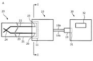
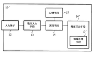
図1に、本実施形態に係る温度校正装置10を用いた温度計測装置Aを示す。
温度計測装置Aは、異種金属からなり、一端側の側温用接点で相互に接続すると共に、他端に一対の外部接点を有する一対の薄膜を備えた薄膜熱電対素子20と、入力された電圧を用いて温度を算出し、算出された温度を表示する温度表示装置30と、薄膜熱電対素子20と温度表示装置30との間に接続される温度校正装置10を主要構成要素とするものである。
<Temperature measuring device>
FIG. 1 shows a temperature measurement device A using a
The temperature measuring device A is made of a dissimilar metal, connected to each other by a side temperature contact at one end side, and input to the thin
図1に示すように、温度校正装置10の接続部11に測温素子としての薄膜熱電対素子20の外部接点25及び26が接続され、温度校正装置10の出力用コネクタ19が温度表示装置30の接続手段31に接続されることで温度計測装置Aが構成される。
本実施形態の温度校正装置10は、薄膜熱電対素子20で発生する熱起電力を校正して、測温用接点24の温度を温度表示装置30に表示させるのに対応する校正後電圧に変換する機能を有する。
As shown in FIG. 1, the
The
<薄膜熱電対素子>
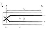
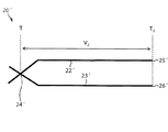
図2は本実施形態に係る温度校正装置10に接続される薄膜熱電対素子20の概略模式図である。
薄膜熱電対素子20は、長尺矩形状のフィルムなどの基板21上に異なる金属からなる一対の薄膜により形成され、長手方向に沿って平行に延びる一対の導電性薄膜22及び23を備えている。一対の導電性薄膜22及び23は、一方の端部側で交差して、交差した箇所は接続して被対象物の測温用である測温用接点24となっている。一対の導電性薄膜22及び23の他端には、開放端となる外部接点25及び26を備えている。
<Thin film thermocouple element>
FIG. 2 is a schematic diagram of the thin
The thin
薄膜熱電対素子20は、外部接点25及び26において、温度校正装置10の接続部11に設けられた一対の入力端子12a及び12bとそれぞれ接続される。
導電性薄膜22及び23はそれぞれ異種材料であり、測温用接点24において、導電性薄膜22及び23が重なるように接合されている。
The thin
The conductive
薄膜熱電対素子20を形成する基板21として、ガラス、フィルム、金属などを用いることができる。但し、基板21を金属などの導電性のある材料とする場合には、予め金属表面にSiO2、Al2O3等の絶縁膜を形成した上で薄膜熱電対素子を形成する必要がある。
したがって、好ましくはフィルムを用いるのが良い。ガラス、フィルムは金属などの導電性のある基板のように、前処理を必要とすることがないため、操作が煩雑になることが無く、好適である。また、フィルムはその可撓性により、薄膜熱電対素子の強度を高めることができる。さらに好ましくは、ポリイミドフィルムを用いるのが良い。ポリイミドフィルムは、折り曲げることが可能で基板を数十ミクロンの厚さにしても壊れにくく取り扱いが容易である点と、200℃を超える温度でも比較的安定している点において、薄膜熱電対素子の基板として適した材料である。
As the
Therefore, it is preferable to use a film. Glass and film are preferable because they do not require pre-treatment unlike conductive substrates such as metals, so that operations are not complicated. Moreover, the film can increase the strength of the thin film thermocouple element due to its flexibility. More preferably, a polyimide film is used. A polyimide film is a thin film thermocouple element in that it can be bent, is easy to handle even when the substrate is several tens of microns thick, is easy to handle, and is relatively stable even at temperatures exceeding 200 ° C. It is a material suitable as a substrate.
基板21の厚さは、1μm以上150μm以下とすることが好ましく、より好ましくは1μm以上50μm以下、特に好ましくは1μm以上18μm以下であるとよい。
The thickness of the
薄膜熱電対素子20の導電性薄膜を構成する異種金属の組み合わせとしては、クロメル−アルメル、PtRh−Pt、クロメル−コンスタンタン、ナイクロシル−ナイシル、Cu−コンスタンタン、Fe−コンスタンタン、Ir−IrRh、W−Re、Au−Pt、Pt−Pd、Bi−Sbなどを用いることができる。好ましくは、使用温度範囲が広く、温度と熱起電力の関係が直線的である、クロメル−アルメルの組み合わせを用いるのが良い。
Examples of combinations of different metals constituting the conductive thin film of the thin
導電性薄膜を形成するための方法としては、スパッタリング法、電子ビーム蒸着法、加熱蒸着法等の真空成膜法や、塗布法等を用いることができる。好ましくは、より薄く均一に薄膜を形成できる真空成膜法を用いるのが良い。さらに好ましくは、蒸着物質との原子組成のずれが少なく、均一に成膜ができるスパッタリング法を用いるのが良い。 As a method for forming the conductive thin film, a vacuum film formation method such as a sputtering method, an electron beam evaporation method, a heating evaporation method, a coating method, or the like can be used. It is preferable to use a vacuum film-forming method that can form a thin film more thinly and uniformly. More preferably, it is preferable to use a sputtering method in which there is little deviation in the atomic composition from the vapor deposition material and uniform film formation is possible.
薄膜熱電対素子20は保護膜により覆われていることが望ましい。保護膜は薄膜熱電対素子の耐環境性を高めると共に、薄膜熱電対素子が外力により変形した際に懸念されるクラックの発生を防ぐ効果もあるためである。適用可能な保護膜は、SiO2、Al2O3などを蒸着法、スパッタリング法、ディッピング法等により形成した絶縁膜、スクリーン印刷法によるポリイミドフィルムなどである。好ましくは、耐熱性および耐薬品性が高く、接着性の高いポリイミドフィルムを用いるのがよい。
The thin
導電性薄膜22及び23の厚さは、50nm以上1μm以下とすることが好ましく、より好ましくは300nm以上500nm以下、より好ましくは100nm以上250nm以下であるとよい。
The thickness of the conductive
<温度校正装置>
本実施形態に係る温度校正装置10は、薄膜熱電対素子20で発生する熱起電力を用いて演算して、測温用接点24の温度を温度表示装置30に表示させるのに対応する校正後電圧に変換する機能を有している。
本実施形態に係る温度校正装置10は、図3に示すように、薄膜熱電対素子20を接続するための接続部11に設けられた一対の入力端子12と、薄膜熱電対素子20で発生する熱起電力が入力される電圧入力手段13と、入力された熱起電力の検出値から校正後電圧を算出する演算手段14と、演算手段14が各種制御を行うのに必要な制御プログラムや各種関係式などが記憶されている記憶手段15と、算出された校正後電圧を出力する電圧印加手段16と、出力端子17と、導線18a,18bと、出力用コネクタ19を含む。
以下、温度校正装置10を構成する各構成要素について詳述する。
<Temperature calibration device>
The
As shown in FIG. 3, the
Hereinafter, each component which comprises the
(接続部及び入力端子)
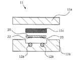
接続部11は、薄膜熱電対素子20の外部接点25及び26を電圧入力手段13と電気的に接続するためのものである。接続部11は、薄膜熱電対素子20の基板21の導電性薄膜22及び23を有しない側に圧着用弾性物を備えている公知の着脱可能な接続構造を有している。
具体的には、図4に示す断面図のように、接続部11は、筺体(蓋側)11a及び筺体(本体側)11bからなり、導電性薄膜22を入力端子12aに、導電性薄膜23を入力端子12bに圧着するため、基板21の導電性薄膜を有しない側に圧着用弾性物11cを備えている。
従って、薄膜熱電対素子20を、接続部11に対して着脱可能に接続することができるため、薄膜熱電対素子20が消耗した場合に、新しい薄膜熱電対素子20と交換することが可能となる。
(Connection and input terminal)
The connecting
Specifically, as shown in the cross-sectional view of FIG. 4, the
Therefore, since the thin
(電圧入力手段)
電圧入力手段13には、導電性薄膜22の外部接点25に接続された接続部11の入力端子12aと、導電性薄膜23の外部接点26に接続された接続部11の入力端子12bとの間に発生する熱起電力が入力される。
電圧入力手段13は、入力された熱起電力をデジタル信号にA/D変換するA/D変換部を含み、A/D変換された熱起電力の検出値を演算手段14へと入力する。
(Voltage input means)
The voltage input means 13 is connected between the
The voltage input means 13 includes an A / D converter that A / D converts the input thermoelectromotive force into a digital signal, and inputs the detected value of the A / D converted thermoelectromotive force to the
(演算手段)
演算手段14は、CPUからなり、記憶手段15に記憶されたプログラムに基づいて温度校正装置10における各種制御を行うための指示信号を出力する制御部としての機能、及び記憶手段15に記憶された関係式に従い各種演算を行う機能を有している。
演算手段14は、電圧入力手段13より入力されるA/D変換された熱起電力の検出値から、記憶手段15に記憶された関係式(例えば、式(1))を参照して用いて、薄膜熱電対素子20の測温用接点24における温度(校正温度)を算出する。
続いて、演算手段14は、記憶手段15に記憶された温度表示装置30の温度算出手段33における入力される電圧と表示温度の関係式(例えば、式(2))に基づいて、薄膜熱電対素子20の測温用接点24における温度(校正温度)を温度表示装置30の温度表示手段32に表示させるのに対応する校正後電圧を算出する。
そして、演算手段14は、算出された校正後電圧を電圧印加手段16に出力する。
(Calculation means)
The calculation means 14 is composed of a CPU, functions as a control unit for outputting instruction signals for performing various controls in the
The calculating means 14 uses the detected value of the A / D converted thermoelectromotive force input from the voltage input means 13 with reference to a relational expression (for example, expression (1)) stored in the storage means 15. Then, the temperature (calibration temperature) at the
Subsequently, the calculation means 14 is based on a relational expression (for example, Expression (2)) between the voltage input to the temperature calculation means 33 of the
Then, the calculation means 14 outputs the calculated post-calibration voltage to the voltage application means 16.
(記憶部)
記憶手段15は、RAM等の記憶媒体からなり、本実施形態の薄膜熱電対で発生する熱起電力の変換方法を実行するための制御プログラム等の演算手段14が各種制御を行うのに必要な制御プログラムや各種関係式などが予め記憶されている。
記憶手段15は、薄膜熱電対素子20の外部接点25と外部接点26との間に発生し、一対の入力端子12a及び12b間の電圧の検出値から測温用接点24の温度を算出する関係式(下記式(1))と、温度表示装置30の温度算出手段33における入力される電圧と表示温度との関係式(下記式(2))が記憶されている。
(Memory part)
The
The storage means 15 is generated between the
記憶手段15に記憶されている一対の入力端子12a及び12b間の電圧の検出値V1から測温用接点24の温度(校正温度)Tを算出する関係式は、以下の式(1)で表わされる。
T=a×V1+T0 (1)
ここで、パラメータaは薄膜熱電対素子における測温用接点と外部接点との間の温度差と、薄膜熱電対素子で発生する熱起電力との関係から求められる近似曲線により算出される勾配定数であり、用いる薄膜熱電対素子20の導電性薄膜を構成する異種金属の組み合わせや導電性薄膜22及び23の厚さ及び長さなどによって決まる値である。
パラメータT0は、バルクの熱電対素子を用いて測定された導電性薄膜22の外部接点25及び26における温度(温度定数)である。
Equation for calculating the temperature (calibration temperature) T of the
T = a × V 1 + T 0 (1)
Here, the parameter a is a gradient constant calculated by an approximate curve obtained from the relationship between the temperature difference between the temperature measuring contact and the external contact in the thin film thermocouple element and the thermoelectromotive force generated in the thin film thermocouple element. The value is determined by the combination of different metals constituting the conductive thin film of the thin
The parameter T 0 is the temperature (temperature constant) at the
記憶手段15に記憶されている温度表示装置30の温度算出手段33における入力される電圧V1’と表示温度Tとの関係式は、以下の式(2)で表わされる。
V1’=T/b (2)
ここで、パラメータbは、バルクの熱電対素子20’における測温用接点と外部接点との間の温度差と、バルクの熱電対素子で発生する熱起電力との関係から求められる近似曲線により算出される定数である。
A relational expression between the input voltage V 1 ′ and the display temperature T in the temperature calculation means 33 of the
V 1 '= T / b (2)
Here, the parameter b is an approximate curve obtained from the relationship between the temperature difference between the temperature measuring contact and the external contact in the
記憶手段15に記憶されている、制御プログラムや上述の関係式などの情報は書き換え可能である。記憶手段15に記憶される情報の書き換えは、温度校正装置10に設けられた不図示の外部通信部(USB端子)を介して、パーソナルコンピュータ(PC)等の外部装置と接続し、外部装置によって情報を書き換えることで行われる。
Information such as the control program and the above-described relational expressions stored in the
(電圧印加手段)
電圧印加手段16は、演算手段14から入力される校正後電圧を発生する機能を有している。電圧印加手段16は、演算手段14から入力される校正後電圧をアナログ信号に変換するD/A変換部を含み、D/A変換された校正後電圧を一対の出力端子17、一対の導線18及び出力用コネクタ19を介して温度表示装置30へと出力する。
(Voltage application means)
The
(出力端子)
出力端子17a及び17bは、一対の導線18a及び18bにそれぞれ接続された導電性材料からなる一対の出力端子17である。出力端子17a及び17bの間には、電圧印加手段16により校正後電圧が出力される。
(Output terminal)
The output terminals 17a and 17b are a pair of
(導線及び出力用コネクタ)
一対の導線18及び出力用コネクタ19は、電圧印加手段16により一対の出力端子17間に出力される校正後電圧を温度表示装置30等の外部装置に入力するための機能を有している。
一対の導線18は、端部に出力用コネクタ19を1つ有しており、該出力用コネクタ19が温度表示装置30の接続手段31に接続される。
一対の導線18の導線18aは一対の出力端子17の出力端子17aに接続されており、一対の導線18の導線18bは一対の出力端子17の出力端子17bに接続されている。
電圧印加手段16により出力端子17a及び17b間に出力された校正後電圧が、温度表示装置30の接続手段31を介して温度算出手段33に入力される。
本実施形態に係る温度校正装置10は、一対の導線18に接続された出力用コネクタ19を1つ有しているのみであり、コネクタを1つ接続可能な1チャンネル式の温度表示装置30に対しても用いることができる。
(Conductor and output connector)
The pair of conductors 18 and the
The pair of conductive wires 18 has one
The
The post-calibration voltage output between the output terminals 17 a and 17 b by the
The
<温度表示装置>
本実施形態の温度計測装置Aで用いられる温度表示装置30は、図5に示すように、コネクタが1つ接続可能な1チャンネル式の接続手段31と、接続手段31を介して入力される電圧を用いて温度を算出する温度算出手段33と、温度算出手段33で算出された温度を表示する温度表示手段32を具備する一般的な温度表示装置又は温度計測装置である。
温度表示装置30の接続手段31には、温度校正装置10の一対の導線18の端部に設けられた出力用コネクタ19が接続される。
<Temperature display device>
As shown in FIG. 5, the
The
図1及び図5における温度表示手段32は、温度表示装置30に設けられた表示部であるが、これに限定されるものではなく、温度表示装置30に、表示画面を備えたPC等の外部装置を接続し、該外部装置の表示画面を温度表示手段32とすることも可能である。
温度算出手段33は、入力される電圧を対応する温度に換算する機能を備えている。
The temperature display means 32 in FIGS. 1 and 5 is a display unit provided in the
The temperature calculation means 33 has a function of converting an input voltage into a corresponding temperature.
温度表示装置30としては、入力される電圧を用いて、対応する温度を算出し、該算出された温度を表示することが可能なものであれば、一般的な温度表示装置を用いることができるが、これに限定されるものではなく、様々な演算機能を備えた温度表示装置等の特殊な温度表示装置を用いることも可能である。
As the
温度校正装置10の演算手段14で演算された校正後電圧が、温度算出手段33に入力される。温度算出手段33は、入力された校正後電圧を用いて、対応する温度を算出し、算出された温度を温度表示手段32に表示する。
温度校正装置10は、薄膜熱電対素子20の測温用接点24における温度が正しく表示されるように、校正後電圧を演算して出力するため、温度表示装置30の温度表示手段32に、測温用接点24の正確な温度を表示することができる。
The post-calibration voltage calculated by the calculation means 14 of the
Since the
<温度校正装置が行う熱起電力の校正>
温度校正装置10における、薄膜熱電対素子20で発生する熱起電力の校正後電圧への変換(校正)について、A.薄膜熱電対素子及びバルクの熱電対素子における温度差と熱起電力の関係、B.温度表示装置における温度表示、C.温度校正装置における演算と共に説明する。
<Calibration of thermoelectromotive force performed by temperature calibration device>
Regarding the conversion (calibration) of the thermoelectromotive force generated in the thin
(A.薄膜熱電対素子及びバルクの熱電対素子における温度差と熱起電力の関係)
薄膜熱電対素子20における温度差と熱起電力の関係は、以下の式(3)で規定される。
t=a×v (3)
ここで、tは測温用接点24と外部接点25,26の間の温度差であり、vは外部接点25と外部接点26との間に発生する熱起電力(薄膜熱電対素子20で発生する熱起電力ともいう)であり、aは温度差tと発生する熱起電力vとの関係から求められる近似曲線により算出される勾配定数である。
(A. Relationship between temperature difference and thermoelectromotive force in thin film thermocouple element and bulk thermocouple element)
The relationship between the temperature difference and the thermoelectromotive force in the thin
t = a × v (3)
Here, t is a temperature difference between the
バルクの熱電対素子20’(K型熱電対素子)における温度差と熱起電力の関係は、以下の式(4)で規定される。
T=b×V (4)
ここで、Tは測温用接点24’と外部接点25’,26’の間の温度差であり、Vは外部接点25’と外部接点26’との間に発生する熱起電力(バルクの熱電対素子20’で発生する熱起電力ともいう)であり、bは温度差Tと発生する熱起電力Vとの関係から求められる近似曲線により算出される勾配定数である。
The relationship between the temperature difference and the thermoelectromotive force in the
T = b × V (4)
Here, T is a temperature difference between the
薄膜熱電対素子20とバルクの熱電対素子20’では、同じ温度差に対して発生する熱起電力が異なる。つまり、T=tのとき、a×V=b×vであるが、V≠vである。
図11は、薄膜熱電対素子20及びバルクの熱電対素子20’の温度−熱起電力特性を示すグラフである。薄膜熱電対素子20で発生する熱起電力は、バルクの熱電対素子20’(K型熱電対素子)で発生する熱起電力と比べて7割程度の大きさである。
The thin
FIG. 11 is a graph showing the temperature-thermoelectromotive force characteristics of the thin
(B.温度表示装置における温度表示)
温度表示装置30は、バルクの熱電対素子20’の温度−熱起電力特性である式(4)を基に温度を表示する。
具体的には、温度表示装置30の温度算出手段33において、バルクの熱電対素子20’の外部接点25’と外部接点26’の間に発生する熱起電力Vに、予め設定されている定数bを乗じることにより温度Tを算出し、温度表示手段32に温度Tを表示する。
(B. Temperature display in temperature display device)
The
Specifically, in the temperature calculation means 33 of the
従って、温度表示装置30に薄膜熱電対素子20を直接接続した場合、実際の温度と温度表示手段32に表示される表示温度が異なってしまう。
表示温度が異なってしまう原因は、一般的な温度表示装置30がバルクの熱電対素子20’の温度−熱起電力特性である式(4)を基に温度を算出するのに対して、薄膜熱電対素子20の温度−熱起電力の関係が式(3)に従うためである。
本実施形態の温度校正装置10では、このずれ量を補正値として使用し、バルクの熱電対素子20’の温度−熱起電力特性の式に合わせる補正を行う。
Therefore, when the thin
The reason why the display temperature is different is that the general
In the
(C.温度校正装置における演算)
図2及び図10に示すように、各熱電対(薄膜熱電対素子20、バルクの熱電対素子20’)の測温用接点24及び24’の温度をT、各熱電対の外部接点25,26,25’,26’の温度をT0とすると、測温用接点と外部接点との間に生じる温度差は、T−T0となる。
(C. Calculation in temperature calibration device)
As shown in FIGS. 2 and 10, the temperature of the
薄膜熱電対素子20について、式(3)から、以下の式(5)が導かれる。
T−T0=a×V1 (5)
ここで、V1は、薄膜熱電対素子20の外部接点25と外部接点26の間に発生する熱起電力である。
For the thin
T−T 0 = a × V 1 (5)
Here, V 1 is a thermoelectromotive force generated between the
バルクの熱電対素子20’について、式(4)から、以下の式(6)が導かれる。
T−T0=b×V2 (6)
ここで、V2は、バルクの熱電対素子20’の外部接点25’と外部接点26’の間に発生する熱起電力である。
For the
T−T 0 = b × V 2 (6)
Here, V 2 is a thermoelectromotive force generated between the
薄膜熱電対素子20を温度表示装置30に接続した場合の温度表示をT1とすると、以下の式(7)が成立する。
T1=b×V1+T0 (7)
When the temperature display when connecting a thin
T 1 = b × V 1 + T 0 (7)
式(7)を変形し、式(5)を変形して得られるV1を代入すると、以下の式(8)が得られる。
T1−T0=(b/a)×(T−T0) (8)
By substituting V 1 obtained by modifying equation (7) and modifying equation (5), the following equation (8) is obtained.
T 1 −T 0 = (b / a) × (T−T 0 ) (8)
ここで、T1は薄膜熱電対素子20を温度表示装置30に接続して計測可能であり、T及びT0はバルクの熱電対素子20’を用いて計測可能であるため、上記式(8)に、T1,T,T0の実測値を代入することで、(b/a)を求めることができる。
Here, T 1 can be measured by connecting the thin
(1/α)=(b/a)とすると、上記式(8)は、以下の式(9)に変形できる。
T=α×T1+(1−α)×T0 (9)
また、この式(9)に、式(7)のT1を代入すると、以下の式(1)に変形できる。
T=(a/b)×b×V1+T0
=a×V1+T0 (1)
When (1 / α) = (b / a), the above equation (8) can be transformed into the following equation (9).
T = α × T 1 + (1−α) × T 0 (9)
Further, by substituting T 1 of equation (7) into this equation (9), it can be transformed into the following equation (1).
T = (a / b) × b × V 1 + T 0
= A x V 1 + T 0 (1)
ここで、T0はバルクの熱電対素子20’により実測することが可能であり、式(4)を用いると以下の式(10)に変換できる。
T=a×V1+b×V0 (10)
従って、式(10)は、特開2010−190735号公報の式(T=aV1+bV2+Tc)においてV2をV0とし、Tc=0とした場合に対応するものである。
Here, T 0 can be actually measured by the
T = a × V 1 + b × V 0 (10)
Therefore, equation (10) corresponds to the case where V 2 is V 0 and T c = 0 in the equation (T = aV 1 + bV 2 + T c ) of Japanese Patent Application Laid-Open No. 2010-190735.
(D.薄膜熱電対素子で発生する熱起電力の校正後電圧への変換)
上述の式(1)において、勾配定数aは薄膜熱電対素子20における温度差と発生する熱起電力との関係から求められる近似曲線により算出することが可能であり、T0(=b×V0)はバルクの熱電対素子20’により実測することが可能であるため、薄膜熱電対素子20の外部接点25と外部接点26の間に発生する熱起電力V1の値から、測温用接点24の温度Tを算出することができる。
(D. Conversion of thermoelectromotive force generated in thin film thermocouple element to post-calibration voltage)
In the above formula (1), the slope constant a can be calculated by an approximate curve obtained from the relationship between the temperature difference in the thin
温度校正装置10の演算手段14は、記憶手段15に記憶されている上述の式(1)を用いて、薄膜熱電対素子20の外部接点25と外部接点26の間に発生する熱起電力V1から薄膜熱電対の測温用接点24における温度Tを校正温度として算出する。
そして、演算手段14は、記憶手段15に記憶された、温度表示装置30の温度算出手段33における入力される電圧と温度の関係式である上述の式(2)に基づいて、校正温度Tを温度表示手段32に表示させるのに対応する校正後電圧V1’を電圧印加手段16に発生させる。
The calculation means 14 of the
Then, the calculation means 14 calculates the calibration temperature T based on the above-described expression (2), which is a relational expression between the voltage and temperature input in the temperature calculation means 33 of the
従って、薄膜熱電対素子20と温度表示装置30の間に、本実施形態に係る温度校正装置10を接続することによって、測温用接点における温度Tを温度表示装置30の温度表示手段32に表示させることができる。
Accordingly, by connecting the
<温度校正装置を用いた温度測定方法>
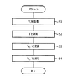
本実施形態に係る温度校正装置10を用いた温度測定方法は、図6に示すように、温度校正装置を用いた温度計測装置を準備する準備工程(ステップS10)と、前記準備工程で準備した温度計測装置を用いて温度の測定を行う温度測定工程(ステップS20)と、前記温度測定工程で測定した温度を温度表示装置に表示する温度表示工程(ステップS30)と、を行うことを特徴とする。
<Temperature measurement method using temperature calibration device>
As shown in FIG. 6, the temperature measurement method using the
(A.準備工程)
準備工程(ステップS10)では、まず、温度校正装置10の記憶手段15に、薄膜熱電対素子20で発生し、一対の入力端子12間で検出される検出値としての熱起電力V1から校正温度としての測温用接点の温度Tを算出するための関係式(例えば、式(1))と、算出された測温用接点の温度Tを温度表示装置30に表示させるのに対応する校正後電圧V1’を算出するための関係式(例えば、式(2))を記憶させる記憶工程を行う。
(A. Preparation process)
In the preparation step (step S 10), first, calibration is performed from the thermoelectromotive force V 1 as a detection value generated in the thin
具体的には、予め測定した定数a及びT0(=b×V0)を代入した式(1)を記憶手段15に記憶させる。同様に、温度校正装置10と共に用いる温度表示装置30の温度算出手段33における入力される電圧と表示温度との関係式である式(2)を記憶手段15に記憶させる。
Specifically, the
記憶手段15に記憶させる情報の記憶は、温度校正装置10に設けられた不図示の外部入力部(USB端子)を介して、パーソナルコンピュータ(PC)等の外部装置と接続することで行われる。
この記憶工程は、温度校正装置10を用いて温度測定を行うユーザーが行うことができるが、温度校正装置10を製造する段階において製造者が行ってもよいし、温度校正装置10を販売する段階において販売者が行ってもよい。
Information stored in the
This storage process can be performed by a user who measures the temperature using the
次に、上述の記憶工程で記憶手段15に関係式を記憶させた温度校正装置10と、薄膜熱電対素子20と、温度表示装置30とを用いて、温度計測装置Aを組み立てる組み立て工程を行う。
組み立て工程では、図1に示すように、温度校正装置10の接続部11に測温素子としての薄膜熱電対素子20の外部接点25及び26を接続し、温度校正装置10の出力用コネクタ19を温度表示装置30の接続手段31に接続することで、温度計測装置Aを組み立てる。
Next, an assembling process for assembling the temperature measuring device A is performed using the
In the assembly process, as shown in FIG. 1, the
(B.温度測定工程)
上述の準備工程に引き続いて、温度校正装置10を用いた温度計測装置Aを用いた温度測定工程(ステップS20)では、本実施形態に係る薄膜熱電対素子で発生する熱起電力の変換方法が実行される。
(B. Temperature measurement process)
Subsequent to the above preparation step, in the temperature measurement step (step S20) using the temperature measurement device A using the
本実施形態に係る薄膜熱電対で発生する熱起電力の変換方法は、図7に示すように、基板上に異なる金属からなる一対の薄膜により形成され、一端側に測温用接点を有し、他端側に各薄膜の外部接点を備えた薄膜熱電対で発生する熱起電力を検出する熱起電力検出工程(ステップS1)と、検出された前記熱起電力を用いて演算して校正後電圧を変換する演算工程(ステップS2及びステップS3)と、算出された前記校正後電圧を出力する校正後電圧出力工程(ステップS4)と、を行い、前記演算工程では、前記熱起電力検出工程で検出された熱起電力を演算して、前記測温用接点の温度を算出し(ステップS2)、前記算出された温度を温度表示装置に表示するのに対応する校正後電圧を算出する(ステップS3)ことを特徴とする。
以下、各工程について図7を参照して詳細に説明する。図7のプログラム処理に関する制御プログラムは記憶手段15に記憶されており、演算手段14を構成するCPU14が記憶手段15に記憶された制御プログラムに基づいてプログラム処理を制御する。
As shown in FIG. 7, the conversion method of the thermoelectromotive force generated by the thin film thermocouple according to this embodiment is formed of a pair of thin films made of different metals on a substrate, and has a temperature measuring contact on one end side. , A thermoelectromotive force detection step (step S1) for detecting a thermoelectromotive force generated by a thin film thermocouple having an external contact of each thin film on the other end side, and calculating and calibrating using the detected thermoelectromotive force A calculation step (step S2 and step S3) for converting the post-voltage and a post-calibration voltage output step (step S4) for outputting the calculated post-calibration voltage are performed. In the calculation step, the thermoelectromotive force detection is performed. The thermoelectromotive force detected in the process is calculated to calculate the temperature of the temperature measuring contact (step S2), and a post-calibration voltage corresponding to displaying the calculated temperature on the temperature display device is calculated. (Step S3).
Hereinafter, each step will be described in detail with reference to FIG. A control program related to the program processing of FIG. 7 is stored in the storage means 15, and the
温度校正装置10の接続部11に薄膜熱電対素子20が接続され、温度校正装置10の出力用コネクタ19が温度表示装置30の接続手段31に接続されると、図7のプログラム処理がスタートする。
When the thin
(熱起電力検出工程)
図7のプログラム処理がスタートすると、まず、ステップS1(熱起電力検出工程)で、基板21上に異なる金属からなる一対の導電性薄膜22,23により形成され、一端側に測温用接点24を有し、他端側に各薄膜の外部接点25,26を備えた薄膜熱電対素子20で発生する熱起電力V1を取得する。
具体的には、CPU14が、一対の入力端子12に入力され、電圧入力手段13でデジタル信号にA/D変換された薄膜熱電対素子20の外部接点間に発生する熱起電力V1を検出する。
(Thermoelectric detection process)
When the program processing of FIG. 7 starts, first, in step S1 (thermoelectromotive force detection step), a pair of conductive
Specifically, the
(演算工程)
演算工程(ステップS2及びステップS3)では、熱起電力検出工程で検出された熱起電力V1を用いて演算して校正後電圧V1’を算出する。
具体的には、CPU14が、記憶手段15に記憶された関係式(例えば、式(1))を参照し、電圧入力手段13でA/D変換された熱起電力V1から、薄膜熱電対素子20の測温用接点24における温度Tを算出する(ステップS2)。
(Calculation process)
In the calculation process (step S2 and step S3), the post-calibration voltage V 1 ′ is calculated by calculation using the thermoelectromotive force V 1 detected in the thermoelectromotive force detection process.
Specifically, the
次に、CPU14が、記憶手段15に記憶された、温度表示装置30の温度算出手段33における入力される電圧信号と表示温度の関係式(例えば、式(2))を参照して、薄膜熱電対素子20の測温用接点24における温度T(校正温度)を温度表示手段32に表示させるのに対応する校正後電圧V1’を算出する(ステップS3)。
Next, the
(校正後電圧出力工程)
校正後電圧出力工程(ステップS4)では、演算工程で算出された校正後電圧V1’を出力する。
具体的には、CPU14は、算出された校正後電圧V1’を電圧印加手段16においてアナログ信号にD/A変換させ、D/A変換された校正後電圧V1’を一対の出力端子17間に出力し、一対の導線18及び出力用コネクタ19を介して温度表示装置30へと出力させる。
(Voltage output process after calibration)
In the post-calibration voltage output step (step S4), the post-calibration voltage V 1 ′ calculated in the calculation step is output.
Specifically, the CPU 14 D / A converts the calculated post-calibration voltage V 1 ′ into an analog signal in the
校正後電圧出力工程(ステップS4)で校正後電圧V1’を出力した後、プログラム処理が終了する。
図5のプログラム処理は、薄膜熱電対素子20を用いて温度を測定する際に目的に応じて、所定の間隔及び回数で断続的に繰り返されるものであっても、所定期間連続して繰り返されるものであってもよい。
After outputting the post-calibration voltage V 1 ′ in the post-calibration voltage output step (step S4), the program processing ends.
The program processing of FIG. 5 is repeated continuously for a predetermined period even if it is intermittently repeated at a predetermined interval and number of times according to the purpose when measuring the temperature using the thin
本実施形態に係る薄膜熱電対で発生する熱起電力の変換方法によって、薄膜熱電対素子20で発生する熱起電力V1が、測温用接点24における温度Tを温度表示装置30の温度表示手段32に表示させるのに対応する校正後電圧V1’に変換され、変換された校正後電圧V1’が出力される。
The thermoelectromotive force V 1 generated in the thin
(C.温度表示工程)
上述の温度測定工程に引き続いて、校正温度Tに対応する校正後電圧V1’に基づいて温度表示装置30に校正温度Tを表示する温度表示工程(ステップS30)が行われる。
温度表示工程では、上述の薄膜熱電対で発生する熱起電力の変換方法により変換された校正後電圧V1’に基づき、測温用接点24における温度T(校正温度)が、温度表示装置30の温度表示手段32に表示される。
(C. Temperature display process)
Subsequent to the temperature measurement step described above, a temperature display step (step S30) for displaying the calibration temperature T on the
In the temperature display step, based on the post-calibration voltage V 1 ′ converted by the conversion method of the thermoelectromotive force generated by the thin film thermocouple, the temperature T (calibration temperature) at the
従って、温度校正装置を用いた温度測定方法によれば、薄膜熱電対素子20を用いた場合であっても、従来汎用されている温度表示装置30をそのまま使用して、測温用接点24における正確な温度を表示させることが可能となる。
Therefore, according to the temperature measurement method using the temperature calibration device, even when the thin
本実施形態では、主として本発明に係る温度校正装置、温度校正装置を用いた温度計測装置、薄膜熱電対で発生する熱起電力の変換方法、及び温度校正装置を用いた温度測定方法について説明した。
ただし、上記の実施形態は、本発明の理解を容易にするための一例に過ぎず、本発明を限定するものではない。本発明は、その趣旨を逸脱することなく、変更、改良され得ると共に、本発明にはその等価物が含まれることは勿論である。
In the present embodiment, the temperature calibration device according to the present invention, the temperature measurement device using the temperature calibration device, the conversion method of the thermoelectromotive force generated in the thin film thermocouple, and the temperature measurement method using the temperature calibration device have been described. .
However, said embodiment is only an example for making an understanding of this invention easy, and does not limit this invention. The present invention can be changed and improved without departing from the gist thereof, and the present invention includes the equivalents thereof.
<変形例>
上述の実施形態では、温度校正装置10の一対の導線18の端部に設けられた出力用コネクタ19を温度表示装置30の接続手段31に有線接続する例を示したが、温度校正装置10と温度表示装置30との接続は有線接続に限られるものではなく、無線通信による接続であってもよい。
<Modification>
In the above-described embodiment, an example in which the
例えば、図8に示すように、一対の出力端子17の代わりに、温度校正装置10’の電圧印加手段16’に無線送信手段17’を設け、演算手段14で演算された校正後電圧を外部へと無線送信可能とする。
For example, as shown in FIG. 8, instead of a pair of
一方、図9に示すように、温度表示装置30’は無線受信手段34を有しており、温度校正装置10’の無線送信手段17’から送信される校正後電圧を受信するように構成されている。
ここで、温度表示装置30’の無線受信手段34は、温度表示装置30’に元々備わっている機能を利用する以外にも、接続手段31に市販の無線受信機を接続することで、無線受信手段34とすることも可能である。
On the other hand, as shown in FIG. 9, the
Here, the
このように、温度校正装置に無線送信手段17’を設けた場合、導線18及び出力用コネクタ19などの配線が不要となるため、薄膜熱電対素子の使用がより容易になると共に、適用範囲が広くなり、温度表示装置30から離れた場所の温度の計測も可能となる。
In this way, when the wireless calibration means 17 ′ is provided in the temperature calibration device, wiring such as the conductive wire 18 and the
また、無線送信手段17’を搭載した温度校正装置10’と、電圧信号を温度に変換する専用のアプリケーションをインストールした、無線受信手段34を有する温度表示装置30’としてのPC等の外部装置を組み合わせて用いることもできる。
具体的には、温度校正装置10’の無線送信手段17’から送信される校正電圧信号を、温度表示装置30’としての外部装置の無線受信手段34が受信し、専用のアプリケーションによりデータ処理を行い、算出される温度を温度表示装置30’としての外部装置の表示装置上に出力させることも可能である。
In addition, an external device such as a PC as a
Specifically, the calibration voltage signal transmitted from the
上述の実施形態では、式(1)で表わされる関係式を用いて薄膜熱電対素子20に発生する熱起電力V1から薄膜熱電対の測温用接点24における温度Tを校正温度として算出し、式(2)で表わされる関係式を用いて校正温度Tを温度表示手段32に表示させるのに対応する校正後電圧V1’を算出した例を示したが、熱起電力V1から校正後電圧V1’を算出できる関係式であれば、用いる関係式は上記式(1)及び式(2)に限定されるものではない。
In the above-described embodiment, the temperature T at the
例えば、式(1)のTを式(2)に代入して得られる、下記式(11)を用いて薄膜熱電対素子20に発生する熱起電力V1から校正温度Tを温度表示手段32に表示させるのに対応する校正後電圧V1’を算出することも可能である。
V1’=(a×V1+T0)/b (11)
ここで、パラメータaは薄膜熱電対素子における測温用接点と外部接点との間の温度差と、薄膜熱電対素子で発生する熱起電力との関係から求められる近似曲線により算出される勾配定数であり、パラメータT0は、バルクの熱電対素子を用いて測定された導電性薄膜22の外部接点25及び26における温度(温度定数)であり、パラメータbは、バルクの熱電対素子20’における測温用接点と外部接点との間の温度差と、バルクの熱電対素子で発生する熱起電力との関係から求められる近似曲線により算出される定数である。
For example, the temperature display means 32 calculates the calibration temperature T from the thermoelectromotive force V 1 generated in the thin
V 1 ′ = (a × V 1 + T 0 ) / b (11)
Here, the parameter a is a gradient constant calculated by an approximate curve obtained from the relationship between the temperature difference between the temperature measuring contact and the external contact in the thin film thermocouple element and the thermoelectromotive force generated in the thin film thermocouple element. Where the parameter T 0 is the temperature (temperature constant) at the
上述の実施形態では、温度校正装置に接続される薄膜熱電対素子が、異種金属からなり、一端側の側温用接点で相互に接続すると共に、他端に一対の外部接点を有する一対の薄膜を1つ備えた例を示したが、一対の薄膜を2つ以上(一対の薄膜を複数対)備えた多点測定用の薄膜熱電対素子を用いることも可能である。
この場合、温度校正装置を、導電性材料からなる一対の入力端子を2つ以上備えるとともに、導電性材料からなる一対の出力端子を2つ以上備える構成とする。
そして、複数備えられている入力端子間の電圧の検出値をそれぞれ校正して、校正後電圧を演算する演算手段と、複数備えられている出力端子間に、それぞれの校正後電圧を出力する電圧印加手段と、を備え、複数備えられている入力端子が、薄膜熱電対素子に複数設けられている外部接点にそれぞれ接続され、複数備えられている出力端子が温度表示装置に接続されたときに、校正後電圧を、温度表示装置に対して出力する。
このような構成とすることで、多点測定用の薄膜熱電対素子及び温度校正装置を、一つのバルクの熱電対素子と見立てて使用できるため、温度換算などの補正を別途行う必要がなく、既存の一般的な温度表示装置などの設備を変更せずにフィルム形状の多点測定用の薄膜熱電対素子を使用できる。
In the above-described embodiment, the thin film thermocouple element connected to the temperature calibration device is made of a dissimilar metal, and is connected to each other by a side temperature contact on one end side, and a pair of thin films having a pair of external contacts on the other end However, it is also possible to use a thin film thermocouple element for multipoint measurement that includes two or more pairs of thin films (a plurality of pairs of thin films).
In this case, the temperature calibration device has two or more pairs of input terminals made of a conductive material, and two or more pairs of output terminals made of a conductive material.
And the voltage which outputs each calibrated voltage between the calculation means which each calibrates the detection value of the voltage between the input terminals with which it is provided, and calculates the voltage after calibration, and the output terminal with which it is provided with And a plurality of input terminals connected to the external contacts provided in the thin film thermocouple element, respectively, and when the output terminals provided in the plurality are connected to the temperature display device. The post-calibration voltage is output to the temperature display device.
By adopting such a configuration, it is possible to use the thin film thermocouple element and temperature calibration device for multipoint measurement as a single bulk thermocouple element, so there is no need to separately perform corrections such as temperature conversion, A thin film thermocouple element for multipoint measurement of a film shape can be used without changing the equipment such as an existing general temperature display device.
以下、本発明の温度校正装置を用いて温度測定を行った具体的実施例について説明するが、本発明は、これに限定されるものではない。 Hereinafter, although the specific Example which performed temperature measurement using the temperature calibration apparatus of this invention is described, this invention is not limited to this.
まず、温度校正装置10の記憶手段15に、演算手段14が各種制御を行うのに必要な制御プログラム、各種関係式などの情報を予め記憶させた。
記憶手段15に記憶させた関係式は、薄膜熱電対素子20の外部接点25と外部接点26との間に発生する熱起電力V1から測温用接点24の温度Tを算出する関係式(T=a×V1+T0 式(1))と、温度表示装置30の温度算出手段33における入力される電圧V1’と表示温度Tとの関係式(V1’=T/b 式(2))である。
ここで式(1)のパラメータa、T0は、高温側でa=31.581[℃/μV]、T0=25[℃]を用い、また、低温側でa=30.701[℃/μV]、T0=25[℃]を用いた。式(2)のパラメータbはb=24.497[℃/μV]を用いた。
First, information such as a control program and various relational expressions necessary for the calculation means 14 to perform various controls was stored in the storage means 15 of the
The relational expression stored in the storage means 15 is a relational expression for calculating the temperature T of the
Here, the parameters a and T 0 in the formula (1) use a = 31.581 [° C./μV] and T 0 = 25 [° C.] on the high temperature side, and a = 30.701 [° C. on the low temperature side. / ΜV], T 0 = 25 [° C.]. B = 24.497 [° C./μV] was used as the parameter b in the equation (2).
次に、図1に示すように、本実施形態に係る温度校正装置10を、測温素子としての薄膜熱電対素子20と、温度表示装置30との間に接続し、温度計測装置Aを構成した。
具体的には、温度校正装置10の接続部11に薄膜熱電対素子20の外部接点25及び26を接続し、温度校正装置10の出力用コネクタ19を温度表示装置30の接続手段31に接続することで、温度計測装置Aを組み立てた。
Next, as shown in FIG. 1, the
Specifically, the
ここで、本実施例では薄膜熱電対素子20の材料金属として、クロメル−アルメルを用い、スパッタリング法により、ポリイミドフィルムの基板21上に薄膜熱電対を形成した。さらに、薄膜熱電対に基板21とは異なるポリイミドフィルムを接着し、それを保護膜とした。
In this example, a thin film thermocouple was formed on a
本実施例では、温度表示装置30として、コネクタを1つ接続可能な1チャンネル式の接続手段31と、温度表示手段32と、入力される電圧を対応する温度に換算する温度算出手段33とを具備する一般的な温度表示装置(Kタイプ熱電対用温度計測装置、Agilent社製、34970A)を用いた。
In the present embodiment, the
本実施例における薄膜熱電対素子20により温度を測定した時の、薄膜熱電対の測温用接点24と外部接点25及び26との間にかかる温度差と、熱起電力との関係を図11に示す。薄膜熱電対素子20の熱起電力は、バルクの熱電対素子20’(K型熱電対素子)の熱起電力と比べて7割程度の大きさであった。また、図11には、温度校正後の熱起電力の温度依存性も併せてプロットされている。
FIG. 11 shows the relationship between the temperature difference between the
温度校正装置10は、薄膜熱電対素子20で発生し、一対の入力端子12間で検出される熱起電力(電圧)を、上述の式(1)を用いて、予め評価し算出した勾配定数aで定数倍増幅し、外部接点25及び26の温度T0を加えることにより、測温用接点24の正確な温度Tを校正温度として得ることができる。
ここで、熱起電力が正の値の場合と負の値の場合で式(1)におけるaの値が若干異なるので、aの値も熱起電力の符号に応じて変更した形で式(1)を記憶手段15に記憶しておくことが正確な温度を求める上で望ましい。
The
Here, since the value of a in Equation (1) is slightly different between the case where the thermoelectromotive force is a positive value and the case where it is a negative value, the value of a is also changed in accordance with the sign of the thermoelectromotive force. It is desirable to store 1) in the storage means 15 in order to obtain an accurate temperature.
一般的な温度表示装置30と薄膜熱電対素子20を、本発明の温度校正装置10を用いて接続し、温度測定を行った結果を図12に示す。
図12に示すように、温度表示装置30の温度表示手段32の表示(温度校正装置適用後)は、バルクの熱電対素子20’(バルクのK型熱電対)を用いた場合の温度表示と良い一致を示した。
FIG. 12 shows the result of measuring the temperature by connecting a general
As shown in FIG. 12, the display of the temperature display means 32 of the temperature display device 30 (after application of the temperature calibration device) is a temperature display when a
A 温度計測装置
10,10’ 温度校正装置
11 接続部
11a 筐体(蓋側)
11b 筐体(本体側)
11c 圧着用弾性体
12 一対の入力端子
12a,12b 入力端子
13 電圧入力手段
14 演算手段(CPU)
15 記憶手段
16 電圧印加手段
17 出力端子
17’ 無線送信部
18 一対の導線
18a,18b 導線
19 出力用コネクタ
20 薄膜熱電対素子
21 基板
22,23 導電性薄膜
24 測温用接点
25,26 外部接点
20’ バルクの熱電対素子
22’,23’ 金属線
24’ 測温用接点
25’,26’ 外部接点
30,30’ 温度表示装置
31 接続手段
32 温度表示手段
33 温度算出手段
34 無線受信手段
A
11b Housing (main body side)
11c Elastic body for pressure bonding 12 Pair of
DESCRIPTION OF
Claims (7)
入力された電圧を用いて温度を算出し、算出された温度を表示する温度表示装置と、
前記薄膜熱電対素子及び前記温度表示装置の間に接続された温度校正装置と、を備え、
前記温度校正装置は、
導電性材料からなり、前記一対の外部接点にそれぞれ接続された少なくとも一対の入力端子と、
前記温度表示装置に連結された一対の導線にそれぞれ接続された導電性材料からなる少なくとも一対の出力端子と、
前記少なくとも一対の入力端子間の電圧の検出値を校正して、校正後電圧を演算する演算手段と、
前記少なくとも一対の出力端子間に、前記校正後電圧を出力する電圧印加手段と、を備え、
前記温度表示装置は、前記少なくとも一対の出力端子及び前記一対の導線を介して入力された前記校正後電圧を用いて校正温度を算出し、算出した校正温度を表示することを特徴とする温度計測装置。 A thin film thermocouple element comprising at least one pair of thin films made of dissimilar metals and connected to each other by a side temperature contact at one end and having a pair of external contacts at the other end;
A temperature display device that calculates the temperature using the input voltage and displays the calculated temperature;
A temperature calibration device connected between the thin film thermocouple element and the temperature display device,
The temperature calibration device is
Made of a conductive material, and at least a pair of input terminals respectively connected to the pair of external contacts;
At least a pair of output terminals each made of a conductive material connected to a pair of conductors connected to the temperature display device;
A calculation means for calibrating a detected value of the voltage between the at least one pair of input terminals and calculating a post-calibration voltage,
Voltage applying means for outputting the post-calibration voltage between the at least one pair of output terminals,
The temperature display device calculates a calibration temperature using the post-calibration voltage input through the at least one pair of output terminals and the pair of conductive wires, and displays the calculated calibration temperature. apparatus.
該出力用コネクタの数は1つであることを特徴とする請求項1記載の温度計測装置。 An output connector connected to the pair of conductors;
The temperature measuring device according to claim 1, wherein the number of output connectors is one.
導電性材料からなり、前記一対の外部接点にそれぞれ接続可能な少なくとも一対の入力端子と、
入力された電圧を用いて温度を算出し、算出された温度を表示する温度表示装置に連結された前記一対の導線に、それぞれ接続可能で、導電性材料からなる少なくとも一対の出力端子と、
前記少なくとも一対の入力端子間の電圧の検出値を校正して、校正後電圧を演算する演算手段と、
前記少なくとも一対の出力端子間に、前記校正後電圧を出力する電圧印加手段と、を備え、
前記少なくとも一対の入力端子が、前記薄膜熱電対素子の前記一対の外部接点に接続され、前記少なくとも一対の出力端子が前記温度表示装置に接続されたときに、前記校正後電圧を、前記温度表示装置に対して出力することを特徴とする温度校正装置。 A temperature calibration device that is made of a dissimilar metal and is connected to each other by a side temperature contact at one end and connected to a thin film thermocouple element having at least one pair of thin films having a pair of external contacts at the other end. And
Made of a conductive material, and at least a pair of input terminals each connectable to the pair of external contacts;
Calculate the temperature using the input voltage, and can be connected to each of the pair of conductors connected to the temperature display device that displays the calculated temperature, and at least a pair of output terminals made of a conductive material,
A calculation means for calibrating a detected value of the voltage between the at least one pair of input terminals and calculating a post-calibration voltage,
Voltage applying means for outputting the post-calibration voltage between the at least one pair of output terminals,
When the at least one pair of input terminals are connected to the pair of external contacts of the thin film thermocouple element and the at least one pair of output terminals are connected to the temperature display device, the post-calibration voltage is displayed as the temperature display. A temperature calibration device characterized in that it outputs to the device.
該出力用コネクタの数は1つであることを特徴とする請求項3記載の温度校正装置。 An output connector connected to the pair of conductors;
4. The temperature calibration apparatus according to claim 3, wherein the number of output connectors is one.
前記一対の入力端子間の電圧の検出値をV1としたときに、予め設定された温度定数T0及び勾配定数aを用いて、式(1)により、前記校正温度Tを算出し、
T=a×V1+T0 (1)
該校正温度T及び予め設定された定数bを用いて、式(2)により、前記校正後電圧V1’を算出することを特徴とする請求項3又は4記載の温度校正装置。
V1’=T/b (2)
(但し、パラメータaは薄膜熱電対素子における測温用接点と外部接点との間の温度差と、薄膜熱電対素子で発生する熱起電力との関係から求められる近似曲線により算出される値であり、パラメータT0は、薄膜熱電対素子の外部接点における温度であり、パラメータbは、バルクの熱電対素子における測温用接点と外部接点との間の温度差と、バルクの熱電対素子で発生する熱起電力との関係から求められる近似曲線により算出される定数である。) The computing means is
When the detected value of the voltage between the pair of input terminals is V 1 , the calibration temperature T is calculated by the equation (1) using the preset temperature constant T 0 and the gradient constant a,
T = a × V 1 + T 0 (1)
5. The temperature calibration apparatus according to claim 3, wherein the post-calibration voltage V 1 ′ is calculated by the equation (2) using the calibration temperature T and a preset constant b.
V 1 '= T / b (2)
(However, the parameter a is a value calculated from an approximate curve obtained from the relationship between the temperature difference between the temperature measuring contact and the external contact in the thin film thermocouple element and the thermoelectromotive force generated in the thin film thermocouple element. Yes, parameter T 0 is the temperature at the external contact of the thin film thermocouple element, and parameter b is the temperature difference between the temperature measuring contact and the external contact in the bulk thermocouple element, and the bulk thermocouple element (It is a constant calculated from the approximate curve obtained from the relationship with the generated thermoelectromotive force.)
Priority Applications (8)
| Application Number | Priority Date | Filing Date | Title |
|---|---|---|---|
| JP2018080893A JP7128645B2 (en) | 2018-04-19 | 2018-04-19 | Temperature calibration device and temperature measurement device |
| TW108204605U TWM584889U (en) | 2018-04-19 | 2019-04-16 | Temperature calibration device and temperature measuring device |
| TW108113152A TW201944038A (en) | 2018-04-19 | 2019-04-16 | Temperature calibration device and temperature measurement device |
| PCT/JP2019/016707 WO2019203327A1 (en) | 2018-04-19 | 2019-04-18 | Temperature calibration device and temperature measurement device |
| CN201980025307.8A CN111971537A (en) | 2018-04-19 | 2019-04-18 | Temperature correction device and temperature measurement device |
| EP19788221.0A EP3783324A4 (en) | 2018-04-19 | 2019-04-18 | TEMPERATURE CALIBRATION DEVICE AND TEMPERATURE MEASURING DEVICE |
| KR1020207032935A KR20210002543A (en) | 2018-04-19 | 2019-04-18 | Temperature calibration device and temperature measuring device |
| US17/047,535 US20210116309A1 (en) | 2018-04-19 | 2019-04-18 | Temperature calibration device and temperature measurement device |
Applications Claiming Priority (1)
| Application Number | Priority Date | Filing Date | Title |
|---|---|---|---|
| JP2018080893A JP7128645B2 (en) | 2018-04-19 | 2018-04-19 | Temperature calibration device and temperature measurement device |
Publications (2)
| Publication Number | Publication Date |
|---|---|
| JP2019190884A true JP2019190884A (en) | 2019-10-31 |
| JP7128645B2 JP7128645B2 (en) | 2022-08-31 |
Family
ID=68238934
Family Applications (1)
| Application Number | Title | Priority Date | Filing Date |
|---|---|---|---|
| JP2018080893A Active JP7128645B2 (en) | 2018-04-19 | 2018-04-19 | Temperature calibration device and temperature measurement device |
Country Status (7)
| Country | Link |
|---|---|
| US (1) | US20210116309A1 (en) |
| EP (1) | EP3783324A4 (en) |
| JP (1) | JP7128645B2 (en) |
| KR (1) | KR20210002543A (en) |
| CN (1) | CN111971537A (en) |
| TW (2) | TWM584889U (en) |
| WO (1) | WO2019203327A1 (en) |
Cited By (2)
| Publication number | Priority date | Publication date | Assignee | Title |
|---|---|---|---|---|
| JP2021173753A (en) * | 2020-04-30 | 2021-11-01 | ザ・スウォッチ・グループ・リサーチ・アンド・ディベロップメント・リミテッド | Method for calibrating at least one electronic temperature sensor |
| JP2023128512A (en) * | 2022-03-03 | 2023-09-14 | ジオマテック株式会社 | Thin film thermocouple element and method for manufacturing thin film thermocouple element |
Families Citing this family (4)
| Publication number | Priority date | Publication date | Assignee | Title |
|---|---|---|---|---|
| JP7558027B2 (en) * | 2020-10-15 | 2024-09-30 | ジオマテック株式会社 | Thin-film thermocouple element, temperature measuring element, and method for manufacturing thin-film thermocouple element |
| CN113091933B (en) * | 2021-03-23 | 2024-12-06 | 上海导向医疗系统有限公司 | Temperature measuring equipment, system, method, device, electronic equipment and medium |
| CN113834579B (en) * | 2021-09-22 | 2024-10-22 | 河南中孚实业股份有限公司 | A constant temperature field acquisition device for double-needle thermocouple calibration |
| CN121890314A (en) * | 2023-08-25 | 2026-04-17 | 应用材料公司 | Dual manufacturing process and calibration for achieving high precision thermocouple substrate |
Citations (5)
| Publication number | Priority date | Publication date | Assignee | Title |
|---|---|---|---|---|
| JPS5258554A (en) * | 1975-11-10 | 1977-05-14 | Mitsubishi Heavy Ind Ltd | Thermocouple emf-temperature signal converter |
| JPH09264768A (en) * | 1996-03-28 | 1997-10-07 | Matsushita Electric Ind Co Ltd | Sensor module |
| JP2007139530A (en) * | 2005-11-17 | 2007-06-07 | Dainippon Printing Co Ltd | Thin thermocouple and manufacturing method thereof |
| JP2010096507A (en) * | 2008-10-14 | 2010-04-30 | Hioki Ee Corp | Thermocouple thermometer |
| JP2010151729A (en) * | 2008-12-26 | 2010-07-08 | Yokogawa Electric Corp | Measuring system |
Family Cites Families (4)
| Publication number | Priority date | Publication date | Assignee | Title |
|---|---|---|---|---|
| JP2007085880A (en) * | 2005-09-22 | 2007-04-05 | Dainippon Printing Co Ltd | Thin thermocouple and manufacturing method thereof |
| CN101339692B (en) * | 2007-07-06 | 2011-01-05 | 鸿富锦精密工业(深圳)有限公司 | Electric thermo-couple temperature collection system and method |
| JP5253222B2 (en) * | 2009-02-18 | 2013-07-31 | ジオマテック株式会社 | Temperature measuring element and temperature measuring instrument |
| US8118484B2 (en) * | 2009-03-31 | 2012-02-21 | Rosemount Inc. | Thermocouple temperature sensor with connection detection circuitry |
-
2018
- 2018-04-19 JP JP2018080893A patent/JP7128645B2/en active Active
-
2019
- 2019-04-16 TW TW108204605U patent/TWM584889U/en not_active IP Right Cessation
- 2019-04-16 TW TW108113152A patent/TW201944038A/en unknown
- 2019-04-18 US US17/047,535 patent/US20210116309A1/en not_active Abandoned
- 2019-04-18 WO PCT/JP2019/016707 patent/WO2019203327A1/en not_active Ceased
- 2019-04-18 KR KR1020207032935A patent/KR20210002543A/en not_active Withdrawn
- 2019-04-18 EP EP19788221.0A patent/EP3783324A4/en not_active Withdrawn
- 2019-04-18 CN CN201980025307.8A patent/CN111971537A/en active Pending
Patent Citations (5)
| Publication number | Priority date | Publication date | Assignee | Title |
|---|---|---|---|---|
| JPS5258554A (en) * | 1975-11-10 | 1977-05-14 | Mitsubishi Heavy Ind Ltd | Thermocouple emf-temperature signal converter |
| JPH09264768A (en) * | 1996-03-28 | 1997-10-07 | Matsushita Electric Ind Co Ltd | Sensor module |
| JP2007139530A (en) * | 2005-11-17 | 2007-06-07 | Dainippon Printing Co Ltd | Thin thermocouple and manufacturing method thereof |
| JP2010096507A (en) * | 2008-10-14 | 2010-04-30 | Hioki Ee Corp | Thermocouple thermometer |
| JP2010151729A (en) * | 2008-12-26 | 2010-07-08 | Yokogawa Electric Corp | Measuring system |
Cited By (4)
| Publication number | Priority date | Publication date | Assignee | Title |
|---|---|---|---|---|
| JP2021173753A (en) * | 2020-04-30 | 2021-11-01 | ザ・スウォッチ・グループ・リサーチ・アンド・ディベロップメント・リミテッド | Method for calibrating at least one electronic temperature sensor |
| JP7238005B2 (en) | 2020-04-30 | 2023-03-13 | ザ・スウォッチ・グループ・リサーチ・アンド・ディベロップメント・リミテッド | Method for calibrating at least one electronic temperature sensor |
| JP2023128512A (en) * | 2022-03-03 | 2023-09-14 | ジオマテック株式会社 | Thin film thermocouple element and method for manufacturing thin film thermocouple element |
| JP7818989B2 (en) | 2022-03-03 | 2026-02-24 | ジオマテック株式会社 | Thin film thermocouple element and method for manufacturing thin film thermocouple element |
Also Published As
| Publication number | Publication date |
|---|---|
| TWM584889U (en) | 2019-10-11 |
| EP3783324A4 (en) | 2021-06-30 |
| CN111971537A (en) | 2020-11-20 |
| EP3783324A1 (en) | 2021-02-24 |
| US20210116309A1 (en) | 2021-04-22 |
| WO2019203327A1 (en) | 2019-10-24 |
| KR20210002543A (en) | 2021-01-08 |
| JP7128645B2 (en) | 2022-08-31 |
| TW201944038A (en) | 2019-11-16 |
Similar Documents
| Publication | Publication Date | Title |
|---|---|---|
| JP7128645B2 (en) | Temperature calibration device and temperature measurement device | |
| JP5253222B2 (en) | Temperature measuring element and temperature measuring instrument | |
| EP3109607B1 (en) | Method for temperature drift compensation of temperature measurement device using thermocouple | |
| US20120065923A1 (en) | Integrated cold junction compensation circuit for thermocouple connections | |
| RU2757064C1 (en) | Heat flow sensor with increased heat exchange | |
| US7982580B2 (en) | High vibration thin film RTD sensor | |
| US9677947B2 (en) | Temperature sensor | |
| US20180238744A1 (en) | Temperature Measuring Device with Reference Temperature Determination | |
| US20220170800A1 (en) | Temperature measurement device and temperature measurement method | |
| RU2521726C1 (en) | Resistance temperature detector | |
| WO2018210580A1 (en) | Thermocouple arrangement and method for measuring temperatures | |
| JPH01288742A (en) | Temperature sensor using thermocouple | |
| EP4553466B1 (en) | Fast and accurate compensation method in a thermocouple measurement, and a respective device | |
| JP2014181955A (en) | Electronic device and measurement data process method | |
| US12352636B2 (en) | Temperature probe and method for manufacturing a temperature probe | |
| EP3052910B1 (en) | Infrared sensor | |
| JP7558027B2 (en) | Thin-film thermocouple element, temperature measuring element, and method for manufacturing thin-film thermocouple element | |
| JP7385909B2 (en) | Temperature measuring device and temperature recording device | |
| JPH0233965B2 (en) | ||
| JP2024058357A (en) | Resistance measuring device and resistance measuring method | |
| EP3037793A1 (en) | A thermocouple system and a method for measuring process temperature | |
| JP2023019283A (en) | Device and method for measuring temperature | |
| JPH04318431A (en) | Temperature correcting apparatus for thermocouple |
Legal Events
| Date | Code | Title | Description |
|---|---|---|---|
| A621 | Written request for application examination |
Free format text: JAPANESE INTERMEDIATE CODE: A621 Effective date: 20210406 |
|
| A131 | Notification of reasons for refusal |
Free format text: JAPANESE INTERMEDIATE CODE: A131 Effective date: 20220524 |
|
| A521 | Request for written amendment filed |
Free format text: JAPANESE INTERMEDIATE CODE: A523 Effective date: 20220609 |
|
| TRDD | Decision of grant or rejection written | ||
| A01 | Written decision to grant a patent or to grant a registration (utility model) |
Free format text: JAPANESE INTERMEDIATE CODE: A01 Effective date: 20220802 |
|
| A61 | First payment of annual fees (during grant procedure) |
Free format text: JAPANESE INTERMEDIATE CODE: A61 Effective date: 20220819 |
|
| R150 | Certificate of patent or registration of utility model |
Ref document number: 7128645 Country of ref document: JP Free format text: JAPANESE INTERMEDIATE CODE: R150 |
|
| R250 | Receipt of annual fees |
Free format text: JAPANESE INTERMEDIATE CODE: R250 |