JP2019190897A - Physical quantity sensor module, inclination meter, inertial measuring device, structure monitoring device, and mobile body - Google Patents
Physical quantity sensor module, inclination meter, inertial measuring device, structure monitoring device, and mobile body Download PDFInfo
- Publication number
- JP2019190897A JP2019190897A JP2018081177A JP2018081177A JP2019190897A JP 2019190897 A JP2019190897 A JP 2019190897A JP 2018081177 A JP2018081177 A JP 2018081177A JP 2018081177 A JP2018081177 A JP 2018081177A JP 2019190897 A JP2019190897 A JP 2019190897A
- Authority
- JP
- Japan
- Prior art keywords
- physical quantity
- quantity sensor
- frequency
- output
- sensor module
- Prior art date
- Legal status (The legal status is an assumption and is not a legal conclusion. Google has not performed a legal analysis and makes no representation as to the accuracy of the status listed.)
- Granted
Links
Images





Classifications
-
- G—PHYSICS
- G01—MEASURING; TESTING
- G01C—MEASURING DISTANCES, LEVELS OR BEARINGS; SURVEYING; NAVIGATION; GYROSCOPIC INSTRUMENTS; PHOTOGRAMMETRY OR VIDEOGRAMMETRY
- G01C19/00—Gyroscopes; Turn-sensitive devices using vibrating masses; Turn-sensitive devices without moving masses; Measuring angular rate using gyroscopic effects
- G01C19/56—Turn-sensitive devices using vibrating masses, e.g. vibratory angular rate sensors based on Coriolis forces
- G01C19/5607—Turn-sensitive devices using vibrating masses, e.g. vibratory angular rate sensors based on Coriolis forces using vibrating tuning forks
- G01C19/5614—Signal processing
-
- G—PHYSICS
- G01—MEASURING; TESTING
- G01C—MEASURING DISTANCES, LEVELS OR BEARINGS; SURVEYING; NAVIGATION; GYROSCOPIC INSTRUMENTS; PHOTOGRAMMETRY OR VIDEOGRAMMETRY
- G01C19/00—Gyroscopes; Turn-sensitive devices using vibrating masses; Turn-sensitive devices without moving masses; Measuring angular rate using gyroscopic effects
- G01C19/56—Turn-sensitive devices using vibrating masses, e.g. vibratory angular rate sensors based on Coriolis forces
- G01C19/5783—Mountings or housings not specific to any of the devices covered by groups G01C19/5607 - G01C19/5719
-
- G—PHYSICS
- G01—MEASURING; TESTING
- G01C—MEASURING DISTANCES, LEVELS OR BEARINGS; SURVEYING; NAVIGATION; GYROSCOPIC INSTRUMENTS; PHOTOGRAMMETRY OR VIDEOGRAMMETRY
- G01C9/00—Measuring inclination, e.g. by clinometers, by levels
- G01C9/02—Details
-
- G—PHYSICS
- G01—MEASURING; TESTING
- G01P—MEASURING LINEAR OR ANGULAR SPEED, ACCELERATION, DECELERATION, OR SHOCK; INDICATING PRESENCE, ABSENCE, OR DIRECTION, OF MOVEMENT
- G01P1/00—Details of instruments
- G01P1/02—Housings
- G01P1/023—Housings for acceleration measuring devices
-
- G—PHYSICS
- G01—MEASURING; TESTING
- G01P—MEASURING LINEAR OR ANGULAR SPEED, ACCELERATION, DECELERATION, OR SHOCK; INDICATING PRESENCE, ABSENCE, OR DIRECTION, OF MOVEMENT
- G01P1/00—Details of instruments
- G01P1/07—Indicating devices, e.g. for remote indication
-
- G—PHYSICS
- G01—MEASURING; TESTING
- G01P—MEASURING LINEAR OR ANGULAR SPEED, ACCELERATION, DECELERATION, OR SHOCK; INDICATING PRESENCE, ABSENCE, OR DIRECTION, OF MOVEMENT
- G01P15/00—Measuring acceleration; Measuring deceleration; Measuring shock, i.e. sudden change of acceleration
- G01P15/02—Measuring acceleration; Measuring deceleration; Measuring shock, i.e. sudden change of acceleration by making use of inertia forces using solid seismic masses
- G01P15/08—Measuring acceleration; Measuring deceleration; Measuring shock, i.e. sudden change of acceleration by making use of inertia forces using solid seismic masses with conversion into electric or magnetic values
- G01P15/0802—Details
-
- G—PHYSICS
- G01—MEASURING; TESTING
- G01P—MEASURING LINEAR OR ANGULAR SPEED, ACCELERATION, DECELERATION, OR SHOCK; INDICATING PRESENCE, ABSENCE, OR DIRECTION, OF MOVEMENT
- G01P15/00—Measuring acceleration; Measuring deceleration; Measuring shock, i.e. sudden change of acceleration
- G01P15/02—Measuring acceleration; Measuring deceleration; Measuring shock, i.e. sudden change of acceleration by making use of inertia forces using solid seismic masses
- G01P15/08—Measuring acceleration; Measuring deceleration; Measuring shock, i.e. sudden change of acceleration by making use of inertia forces using solid seismic masses with conversion into electric or magnetic values
- G01P15/09—Measuring acceleration; Measuring deceleration; Measuring shock, i.e. sudden change of acceleration by making use of inertia forces using solid seismic masses with conversion into electric or magnetic values by piezoelectric pick-up
-
- G—PHYSICS
- G01—MEASURING; TESTING
- G01P—MEASURING LINEAR OR ANGULAR SPEED, ACCELERATION, DECELERATION, OR SHOCK; INDICATING PRESENCE, ABSENCE, OR DIRECTION, OF MOVEMENT
- G01P15/00—Measuring acceleration; Measuring deceleration; Measuring shock, i.e. sudden change of acceleration
- G01P15/02—Measuring acceleration; Measuring deceleration; Measuring shock, i.e. sudden change of acceleration by making use of inertia forces using solid seismic masses
- G01P15/08—Measuring acceleration; Measuring deceleration; Measuring shock, i.e. sudden change of acceleration by making use of inertia forces using solid seismic masses with conversion into electric or magnetic values
- G01P15/097—Measuring acceleration; Measuring deceleration; Measuring shock, i.e. sudden change of acceleration by making use of inertia forces using solid seismic masses with conversion into electric or magnetic values by vibratory elements
-
- G—PHYSICS
- G01—MEASURING; TESTING
- G01P—MEASURING LINEAR OR ANGULAR SPEED, ACCELERATION, DECELERATION, OR SHOCK; INDICATING PRESENCE, ABSENCE, OR DIRECTION, OF MOVEMENT
- G01P15/00—Measuring acceleration; Measuring deceleration; Measuring shock, i.e. sudden change of acceleration
- G01P15/18—Measuring acceleration; Measuring deceleration; Measuring shock, i.e. sudden change of acceleration in two or more dimensions
-
- H—ELECTRICITY
- H03—ELECTRONIC CIRCUITRY
- H03M—CODING; DECODING; CODE CONVERSION IN GENERAL
- H03M3/00—Conversion of analogue values to or from differential modulation
- H03M3/30—Delta-sigma modulation
-
- H—ELECTRICITY
- H03—ELECTRONIC CIRCUITRY
- H03M—CODING; DECODING; CODE CONVERSION IN GENERAL
- H03M3/00—Conversion of analogue values to or from differential modulation
- H03M3/30—Delta-sigma modulation
- H03M3/378—Testing
-
- G—PHYSICS
- G01—MEASURING; TESTING
- G01C—MEASURING DISTANCES, LEVELS OR BEARINGS; SURVEYING; NAVIGATION; GYROSCOPIC INSTRUMENTS; PHOTOGRAMMETRY OR VIDEOGRAMMETRY
- G01C9/00—Measuring inclination, e.g. by clinometers, by levels
- G01C9/02—Details
- G01C9/06—Electric or photoelectric indication or reading means
Landscapes
- Physics & Mathematics (AREA)
- General Physics & Mathematics (AREA)
- Engineering & Computer Science (AREA)
- Radar, Positioning & Navigation (AREA)
- Remote Sensing (AREA)
- Theoretical Computer Science (AREA)
- Signal Processing (AREA)
- Gyroscopes (AREA)
- Indication And Recording Devices For Special Purposes And Tariff Metering Devices (AREA)
- Measuring Frequencies, Analyzing Spectra (AREA)
- Measurement Of Mechanical Vibrations Or Ultrasonic Waves (AREA)
- Measuring Fluid Pressure (AREA)
Abstract
【課題】物理量センサーモジュールを大型化することなく、物理量センサーの出力信号の非線形性を補正できる技術を提供すること。【解決手段】物理量センサーモジュール1は、物理量の変化に応じて周波数が変化する周波数変化型物理量センサー3と、基準信号を出力する基準信号発振部5と、周波数変化型物理量センサー3の出力である被測定信号に基づく動作信号を用いて、基準信号を周波数デルタシグマ変調することで周波数デルタシグマ変調信号を生成する周波数デルタシグマ変調部10と、周波数デルタシグマ変調部10の出力側に設けられ、周波数変化型物理量センサー3の出力である被測定信号に同期して動作する第1ローパスフィルター20と、第1ローパスフィルター20の出力側に設けられ、基準信号に同期して動作する第2ローパスフィルター60と、を備える。【選択図】図1An object of the present invention is to provide a technique capable of correcting nonlinearity of an output signal of a physical quantity sensor without increasing the size of a physical quantity sensor module. A physical quantity sensor module includes a frequency-variable physical quantity sensor whose frequency changes in accordance with a change in a physical quantity, a reference signal oscillator that outputs a reference signal, and an output of the frequency-variable physical quantity sensor. Using an operation signal based on the signal under measurement, a frequency delta sigma modulation unit 10 that generates a frequency delta sigma modulation signal by frequency delta sigma modulation of the reference signal, provided on the output side of the frequency delta sigma modulation unit 10, A first low-pass filter 20 that operates in synchronization with a signal to be measured, which is an output of the frequency-variable physical quantity sensor 3, and a second low-pass filter that is provided on the output side of the first low-pass filter 20 and operates in synchronization with a reference signal 60. [Selection diagram] Fig. 1
Description
本発明は、物理量センサーモジュール等に関する。 The present invention relates to a physical quantity sensor module and the like.
加速度等の物理量を検出する物理量センサーモジュールを構成する物理量センサーには、物理量に対する出力値の関係が線形ではない非線形性の問題がある。この非線形性を補正するため、例えば、物理量センサーの一種であって加速度を検出する静電容量型物理量センサーでは、出力の増幅度を切り替える非線形性補正回路を設ける構成が知られている(例えば、特許文献1参照)。 A physical quantity sensor that constitutes a physical quantity sensor module that detects a physical quantity such as acceleration has a problem of non-linearity in which the relationship between the output value and the physical quantity is not linear. In order to correct this non-linearity, for example, a capacitance-type physical quantity sensor that is a kind of physical quantity sensor and detects acceleration is known to have a non-linearity correction circuit that switches output amplification (for example, Patent Document 1).
しかしながら、非線形性補正回路を設けるといった専用の回路や専用の機構を設ける場合には、物理量センサーモジュールの回路規模が増しコストが増大するという課題があった。 However, when a dedicated circuit such as a nonlinearity correction circuit or a dedicated mechanism is provided, there is a problem that the circuit scale of the physical quantity sensor module increases and the cost increases.
本発明は、上記事情に鑑みてなされたものであり、その目的とするところは、物理量センサーモジュールを大型化することなく低コストに物理量センサーモジュールの出力の非線形性を線形に近づける技術を提供することである。 The present invention has been made in view of the above circumstances, and an object of the present invention is to provide a technique for making the nonlinearity of the output of the physical quantity sensor module close to linear at a low cost without increasing the size of the physical quantity sensor module. That is.
上記課題を解決するための第1の発明は、物理量の変化に応じて周波数が変化する周波数変化型物理量センサーと、基準信号を出力する基準信号発振部と、前記周波数変化型物理量センサーから出力された被測定信号に基づく動作信号を用いて、前記基準信号を周波数デルタシグマ変調し、周波数デルタシグマ変調信号を生成する周波数デルタシグマ変調部と、前記周波数デルタシグマ変調部の出力側に設けられ、前記被測定信号に同期して動作する第1のフィルターと、前記第1のフィルターの出力側に設けられ、前記基準信号に同期して動作する第2のフィルターと、を備えている物理量センサーモジュールである。 A first invention for solving the above-described problem is a frequency change type physical quantity sensor whose frequency changes in accordance with a change in physical quantity, a reference signal oscillation unit for outputting a reference signal, and the frequency change type physical quantity sensor. A frequency delta sigma modulation unit that generates a frequency delta sigma modulation signal by using a frequency delta sigma modulation of the reference signal using an operation signal based on the measured signal, and provided on the output side of the frequency delta sigma modulation unit, A physical quantity sensor module comprising: a first filter that operates in synchronization with the signal under measurement; and a second filter that is provided on the output side of the first filter and operates in synchronization with the reference signal It is.
第1の発明によれば、周波数デルタシグマ変調部の出力側に設けられるフィルターを周波数変化型物理量センサーの出力である被測定信号に同期して動作する第1のフィルターと、基準信号に同期して動作する第2のフィルターとの組み合わせとすることにより、前記被測定信号の非線形性を補正することが可能となる。このため、非線形性補正回路を設けるといった専用の回路や専用の機構を設ける必要がなく、物理量センサーモジュールを大型化することなく低コストに物理量センサーから出力される被測定信号の非線形性を補正することが可能となる。 According to the first invention, the filter provided on the output side of the frequency delta-sigma modulation unit is synchronized with the reference signal and the first filter that operates in synchronization with the signal under measurement that is the output of the frequency change type physical quantity sensor. By combining with the second filter that operates, the nonlinearity of the signal under measurement can be corrected. Therefore, it is not necessary to provide a dedicated circuit or a dedicated mechanism such as providing a nonlinearity correction circuit, and the nonlinearity of the signal under measurement output from the physical quantity sensor can be corrected at a low cost without increasing the size of the physical quantity sensor module. It becomes possible.
第2の発明は、第1の発明において、前記第1のフィルター及び前記第2のフィルターの合成により実現されるフィルター特性であるカットオフ周波数が、前記周波数変化型物理量センサーの構造共振周波数よりも低い、物理量センサーモジュールである。 According to a second invention, in the first invention, a cutoff frequency which is a filter characteristic realized by combining the first filter and the second filter is higher than a structural resonance frequency of the frequency change physical quantity sensor. Low physical quantity sensor module.
第2の発明によれば、第1のフィルター及び第2のフィルターによって、振動整流誤差が顕著に現れる構造共振周波数由来のノイズ成分を低減できる。 According to the second invention, the first filter and the second filter can reduce the noise component derived from the structural resonance frequency in which the vibration rectification error appears significantly.
第3の発明は、第2の発明において、前記構造共振周波数は、前記周波数変化型物理量センサーの構造に基づいて決まる周波数である、物理量センサーモジュールである。 A third invention is the physical quantity sensor module according to the second invention, wherein the structural resonance frequency is a frequency determined based on a structure of the frequency change type physical quantity sensor.
第3の発明によれば、構造共振周波数を周波数変化型物理量センサーの構造によって決めることができる。 According to the third invention, the structural resonance frequency can be determined by the structure of the frequency change type physical quantity sensor.
第4の発明は、第1乃至第3の発明の何れかにおいて、前記周波数変化型物理量センサーは、前記物理量に対する出力信号の特性として非線形性を有しており、前記第1のフィルターは、入出力特性が、前記周波数変化型物理量センサーの出力である被測定信号の非線形性を線形に近づけるための特性に設定された、物理量センサーモジュールである。 According to a fourth invention, in any one of the first to third inventions, the frequency change physical quantity sensor has nonlinearity as a characteristic of an output signal with respect to the physical quantity, and the first filter In the physical quantity sensor module, the output characteristic is set to a characteristic for making the non-linearity of the signal under measurement, which is an output of the frequency change type physical quantity sensor, close to linear.
第4の発明によれば、周波数変化型物理量センサーの出力である被測定信号を第1のフィルターに通すことで、前記被測定信号が有する非線形性が線形に近づくように補正されて、物理量センサーモジュールの出力とされる。 According to the fourth invention, the measured signal that is the output of the frequency change type physical quantity sensor is passed through the first filter, so that the nonlinearity of the measured signal is corrected so as to approach linearity, and the physical quantity sensor The output of the module.
第5の発明は、第4の発明において、前記第1のフィルターは、フィルタータップ数によって平滑化タイミングを変更可能な平滑化フィルターであり、前記フィルタータップ数が、前記非線形性によって現れる前記周波数変化型物理量センサーの出力である被測定信号の振動整流誤差を低減させる平滑化タイミングに設定された、物理量センサーモジュールである。 In a fifth aspect based on the fourth aspect, the first filter is a smoothing filter whose smoothing timing can be changed by the number of filter taps, and the frequency change in which the number of filter taps appears due to the non-linearity. This is a physical quantity sensor module set at a smoothing timing for reducing vibration rectification error of a signal under measurement, which is an output of the type physical quantity sensor.
第5の発明によれば、平滑化フィルターである第1のフィルターの平滑化タイミングをフィルタータップ数によって変更することで、周波数変化型物理量センサーの出力である被測定信号の振動整流誤差が低減されるため、前記被測定信号が有する非線形性を補正することができる。 According to the fifth invention, by changing the smoothing timing of the first filter, which is a smoothing filter, according to the number of filter taps, the vibration rectification error of the signal under measurement, which is the output of the frequency change type physical quantity sensor, is reduced. Therefore, the nonlinearity of the signal under measurement can be corrected.
第6の発明は、第5の発明において、前記フィルタータップ数は、外部から設定変更可能である、物理量センサーモジュールである。 A sixth invention is the physical quantity sensor module according to the fifth invention, wherein the number of filter taps can be changed from the outside.
第6の発明によれば、第1フィルターのフィルタータップ数を外部から設定変更可能であるので、物理量センサーモジュール毎に、周波数変化型物理量センサーの特性に応じて第1フィルターのフィルタータップ数を適切に設定する、或いは設定し直すことができるようになる。 According to the sixth invention, since the number of filter taps of the first filter can be set and changed from the outside, the number of filter taps of the first filter is appropriately set according to the characteristics of the frequency change type physical quantity sensor for each physical quantity sensor module. Can be set or reset.
第7の発明は、第5又は第6の発明において、前記第1のフィルターは、前記平滑化タイミングの変更量の粗密が異なる複数のフィルタータップ数で前記平滑タイミングを変更可能である、物理量センサーモジュールである。 A seventh invention is the physical quantity sensor according to the fifth or sixth invention, wherein the first filter is capable of changing the smoothing timing with a plurality of filter taps having different smoothing timing changing amounts. It is a module.
第7の発明によれば、平滑化タイミングの変更量の粗密が異なる複数のフィルタータップ数によって、周波数変化型物理量センサーの出力である被測定信号の非線形性に対する補正の程度の調整が容易になる。 According to the seventh aspect of the present invention, it is easy to adjust the degree of correction for the nonlinearity of the signal under measurement, which is the output of the frequency change type physical quantity sensor, by the plurality of filter taps having different smoothing timing change amounts. .
第8の発明は、第1乃至第5の発明の何れかにおいて、前記物理量は加速度である、物理量センサーモジュールである。 An eighth invention is a physical quantity sensor module according to any one of the first to fifth inventions, wherein the physical quantity is acceleration.
第8の発明によれば、加速度を検出する物理量センサーモジュールにおいて、上述の第1乃至第5の発明の効果を有することができる。 According to the eighth aspect, the physical quantity sensor module for detecting acceleration can have the effects of the first to fifth aspects described above.
第9の発明は、第8の発明の物理量センサーモジュールと、前記物理量センサーモジュールの出力に基づいて傾斜角度を算出する算出部と、を具備した傾斜計である。 A ninth invention is an inclinometer comprising the physical quantity sensor module of the eighth invention and a calculation unit that calculates an inclination angle based on an output of the physical quantity sensor module.
第9の発明によれば、従来よりも傾斜角度の算出精度を高めた傾斜計を実現できる。 According to the ninth aspect of the present invention, it is possible to realize an inclinometer with higher calculation accuracy of the inclination angle than in the past.
第10の発明は、移動体に取り付けられる慣性計測装置であって、第8の発明の物理量センサーモジュールと、角速度物理量センサーモジュールと、前記物理量センサーモジュールの出力と前記角速度物理量センサーモジュールの出力とに基づいて前記移動体の姿勢を算出する回路部と、を具備した慣性計測装置である。 A tenth aspect of the invention is an inertial measurement device attached to a moving body, the physical quantity sensor module of the eighth aspect, an angular velocity physical quantity sensor module, an output of the physical quantity sensor module, and an output of the angular velocity physical quantity sensor module. And a circuit unit for calculating a posture of the mobile body based on the inertial measurement device.
第10の発明によれば、従来よりも移動体の姿勢の算出精度を高めた慣性計測装置を実現できる。 According to the tenth aspect of the invention, an inertial measurement device can be realized that has higher accuracy in calculating the posture of the moving body than in the prior art.
第11の発明は、構造物に取り付けられる第8の発明の物理量センサーモジュールと、前記構造物に取り付けられ、前記物理量センサーモジュールの出力を送信する送信部と、前記送信部からの送信信号を受信する受信部と、前記受信部の受信信号に基づいて前記構造物の傾斜角度を算出する算出部と、を具備した構造物監視装置である。 An eleventh aspect of the invention is the physical quantity sensor module of the eighth aspect of the invention attached to a structure, a transmission unit that is attached to the structure and transmits the output of the physical quantity sensor module, and receives a transmission signal from the transmission unit And a calculating unit that calculates an inclination angle of the structure based on a reception signal of the receiving unit.
第11の発明によれば、従来よりも構造物の傾斜角度の算出精度を高めた構造物監視装置を実現できる。 According to the eleventh aspect of the present invention, a structure monitoring apparatus can be realized in which the calculation accuracy of the inclination angle of the structure is improved as compared with the conventional structure.
第12の発明は、第8の発明の物理量センサーモジュールと、前記物理量センサーモジュールの出力信号に基づいて、加速、制動および操舵のうちの少なくとも1つを制御する制御部と、を具備し、自動運転の実施或いは不実施を、前記物理量センサーモジュールの出力に基づいて切り替える、移動体である。 A twelfth invention includes a physical quantity sensor module according to an eighth invention, and a control unit that controls at least one of acceleration, braking, and steering based on an output signal of the physical quantity sensor module. It is a moving body which switches execution or non-execution based on the output of the physical quantity sensor module.
第12の発明によれば、従来よりも自動運転の品質を高めた移動体を実現できる。 According to the twelfth aspect of the present invention, it is possible to realize a mobile object that has improved the quality of automatic driving as compared with the prior art.
以下、図面を参照して本発明の好適な実施形態について説明する。なお、以下に説明する実施形態によって本発明が限定されるものではなく、本発明を適用可能な形態が以下の実施形態に限定されるものでもない。 Hereinafter, preferred embodiments of the present invention will be described with reference to the drawings. Note that the present invention is not limited to the embodiments described below, and modes to which the present invention can be applied are not limited to the following embodiments.
[第1実施形態]
<構成>
図1は、第1実施形態の物理量センサーモジュール1のブロック構成図である。図1によれば、物理量センサーモジュール1は、周波数変化型物理量センサー3と、基準信号発振部5と、周波数比測定装置7とを備える。周波数変化型物理量センサー3は、検出対象の物理量の変化に応じて周波数が変化する物理量センサーであり、周波数に応じた周期信号を被測定信号として出力する。周波数変化型物理量センサー3は、例えば、物理量である加速度を計測する水晶加速度物理量センサーであってもよいし、物理量である角速度を計測する水晶角速度物理量センサーであってもよい。基準信号発振部5は、予め定められた周波数に基づく基準信号を出力する。この基準信号の周波数は、被測定信号の周波数より高い。
[First Embodiment]
<Configuration>
FIG. 1 is a block configuration diagram of a physical
周波数比測定装置7は、被測定信号と基準信号とに基づいて、被測定信号と基準信号との周波数比を測定する装置である。また、周波数比測定装置7は、レシプロカルカウント方式によって周波数比を測定する。なお、被測定信号ではなく、被測定信号に基づく動作信号としても良い。被測定信号に基づく動作信号とは、被測定信号と相関のある信号であり、被測定信号自体も含まれる。周波数比測定装置7は、周波数デルタシグマ変調部10と、第1ローパスフィルター20と、第3ラッチ50と、第2ローパスフィルター60とを備える。
The frequency ratio measuring device 7 is a device that measures the frequency ratio between the signal under measurement and the reference signal based on the signal under measurement and the reference signal. Further, the frequency ratio measuring device 7 measures the frequency ratio by a reciprocal count method. Note that an operation signal based on the signal under measurement may be used instead of the signal under measurement. The operation signal based on the signal under measurement is a signal correlated with the signal under measurement, and includes the signal under measurement itself. The frequency ratio measuring device 7 includes a frequency delta
周波数デルタシグマ変調部10は、周波数変化型物理量センサー3の出力である被測定信号を用いて、基準信号発振部5から出力された基準信号を周波数デルタシグマ変調し、周波数デルタシグマ変調信号を生成する。周波数デルタシグマ変調部10は、カウンター12と、第1ラッチ14と、第2ラッチ16と、減算器18と、を備える。カウンター12は、基準信号の立ち上がりエッジをカウントしてカウント値を示すカウントデータを出力する。第1ラッチ14は、被測定信号の立ち上がりエッジに同期して、カウントデータをラッチして第1データを出力する。第2ラッチ16は、被測定信号の立ち上がりエッジに同期して、第1データをラッチして第2データを出力する。減算器18は、第1データから第2データを減算して出力データを生成する。この出力が、周波数デルタシグマ変調部10が生成する周波数デルタシグマ変調信号である。
The frequency delta
この周波数デルタシグマ変調部10は、1次の周波数デルタシグマ変調器とも呼ばれ、基準信号のカウント値を、被測定信号によって2回ラッチしており、被測定信号の立ち上がりエッジをトリガーとして、基準信号のカウント値を順次保持する。この例では、立ち上がりエッジでラッチ動作を行う場合を想定しているが、立下りエッジ、もしくは、立ち上がりエッジ及び立下りエッジの両方でラッチ動作を行っても良い。また、減算器18は、保持されている2つのカウント値の差分を演算することで、被測定信号が1周期推移する間に観測される基準信号のカウント値の増分を、時間経過とともに不感期間なく出力する。被測定信号の周波数をfx、基準信号の周波数をfcとしたとき、周波数比は、fc/fx、となる。周波数デルタシグマ変調部10は、周波数比を示す周波数デルタシグマ変調信号を、デジタル信号列として出力するものである。
This frequency delta
第1ローパスフィルター20は、第1のフィルターの一例であり、周波数デルタシグマ変調部10の出力側に設けられ、周波数変化型物理量センサー3の出力である被測定信号に同期して動作し、周波数比測定装置7が出力する周波数デルタシグマ変調信号に含まれるノイズ成分を除去又は低減する。
The first low-
第3ラッチ50は、基準信号の立ち上がりエッジに同期して、第1ローパスフィルター20の出力をラッチして出力する。
The
第2ローパスフィルター60は、第2のフィルターの一例であり、第1のフィルターの一例である第1ローパスフィルター20の出力側に設けられ、基準信号に同期して動作し、周波数比測定装置7が出力する周波数デルタシグマ変調信号に含まれるノイズ成分を除去又は低減する。
The second low-
<原理>
本実施形態の周波数比測定装置7は、周波数変化型物理量センサー3の出力である被測定信号の非線形性を補正する特徴をもつ。周波数変化型物理量センサー3は、例えば、水晶加速度物理量センサーを例にとると、検出軸方向へ作用する力の変化に応じて水晶振動子の発振周波数(振動周波数)が変化することを利用した物理量センサーであり、その発振周波数に対応するパルス状に変化する信号を出力する。作用した加速度と水晶振動子の発振周波数との関係は完全な線形関係にならず(非線形性)、また、その関係性には個体差がある。
<Principle>
The frequency ratio measuring apparatus 7 of the present embodiment has a feature of correcting the nonlinearity of the signal under measurement that is the output of the frequency change type
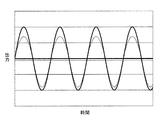
図2は、入出力関係に非線形性を有する系に振動成分を入力すると、出力値の直流成分にドリフトが生じる様子を説明するための模式図である。入出力関係が線形である系に正弦波状の信号を入力すると、図2の実曲線で示される出力値が得られる。この出力値を整流することにより得られる直流成分(実直線)にドリフトは生じない。一方、入出力関係が非線形である系に正弦波状の信号を入力すると、図2の点曲線で示される出力値が得られる。この出力値を整流することにより得られる直流成分(点直線)は、出力波形の歪に起因するドリフトが生じる。上記入出力関係の非線形性を有する系に振動成分を入力した際に出力に生じるドリフト成分を振動整流誤差(VRE:vibration rectification error)と呼んでいる。一般に、VREは入力する振動成分の周波数の関数であり、入力する振動成分の周波数が一定であればVREの大きさは入力する振動成分の振幅の2乗に比例することが知られている。 FIG. 2 is a schematic diagram for explaining how drift occurs in a DC component of an output value when a vibration component is input to a system having nonlinearity in the input / output relationship. When a sinusoidal signal is input to a system in which the input / output relationship is linear, an output value indicated by a solid curve in FIG. 2 is obtained. Drift does not occur in the DC component (solid line) obtained by rectifying this output value. On the other hand, when a sinusoidal signal is input to a system in which the input / output relationship is nonlinear, an output value indicated by a dotted curve in FIG. 2 is obtained. The direct current component (dotted line) obtained by rectifying the output value causes drift due to distortion of the output waveform. A drift component generated in the output when a vibration component is input to the system having nonlinearity in the input / output relationship is called a vibration rectification error (VRE). Generally, VRE is a function of the frequency of the input vibration component, and it is known that the magnitude of VRE is proportional to the square of the amplitude of the input vibration component if the frequency of the input vibration component is constant.
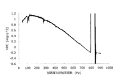
図3は、加速度を検出するよう構成された調整前の物理量センサーモジュール1において、振動整流誤差定数(VRC:Vibration Rectification error Constant)を印加した加速度の印加周波数の関数としてプロットしたものである。VREの大きさは入力する振動成分の振幅の2乗に比例することから、加速度を検出する物理量センサーモジュールにおけるVRCの単位は[G/G^2]で与えられる。820Hz付近に見られるVRCのピークは、他の周波数領域に比べて4〜5桁ほど大きい値となっていることを示しており、これは、物理量センサーモジュールの構造により決まる構造共振において、その構造共振周波数が820Hz程度であり、入力する振動成分に820Hz程度の周波数が含まれると物理量センサーモジュールの構造共振が起こるため、見かけ上、構造共振周波数に対応する周波数成分が増幅されて出力されることに起因する。その結果、構造共振に起因するドリフトがVREへ最も大きく寄与することとなり、特別な対策が必要となる。
FIG. 3 is a plot of the acceleration rectification error constant (VRC) applied as a function of the applied frequency of acceleration in the physical
周波数比測定装置7は、非線形性を有する周波数変化型物理量センサー3の出力である被測定信号に対する補正を行い、特に、構造共振に起因するVREを低減することにより、周波数変化型物理量センサー3に作用した加速度と、周波数比測定装置7の出力との、非線形性を低減することができる。
The frequency ratio measuring device 7 corrects the signal under measurement, which is the output of the frequency-variable
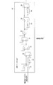
図4は、第1ローパスフィルター20のブロック構成図である。図4によれば、第1ローパスフィルター20は、第1加算器22と、第1遅延素子24と、第1減算器26と、第2加算器28と、第3加算器30と、デシメーター32と、第2遅延素子34と、第2減算器36と、第3遅延素子38と、第3減算器40とを有する。第1ローパスフィルター20の各部は、被測定信号に同期して動作する。フィルタータップ数である第1遅延素子24、第2遅延素子34、第3遅延素子38それぞれの遅延数n1〜n3は、何れも、物理量センサーモジュール1の外部から設定変更が可能である。第1ローパスフィルター20の構成要素のうち、第1加算器22、第1遅延素子24、及び、第1減算器26でなる前段部分は、移動平均フィルターとして機能する。また、第1ローパスフィルター20の構成要素のうち、第2加算器28、第3加算器30、デシメーター32、第2遅延素子34、第2減算器36、第3遅延素子38、及び、第3減算器40でなる後段部分は、CIC(Cascaded Integrator Comb)フィルターとして機能する。
FIG. 4 is a block configuration diagram of the first low-
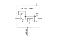
図5は、第2ローパスフィルター60のブロック構成図である。図4によれば、第2ローパスフィルター60は、第4加算器62と、第4遅延素子64と、第4減算器66とを有する。第2ローパスフィルター60の各部は、基準信号に同期して動作する。フィルタータップ数である第4遅延素子64の遅延数n4は、物理量センサーモジュール1の外部から設定変更が可能である。また、第2ローパスフィルター60は、移動平均フィルターとして機能する。
FIG. 5 is a block configuration diagram of the second low-
このように構成される第1ローパスフィルター20のフィルタータップ数n1〜n3、及び、第2ローパスフィルター60のフィルタータップ数n4の設定によって、周波数比測定装置7が有する入出力特性の非線形性を実現している。具体的には、CICフィルターにおけるデシメーション比をRとしたとき、被測定信号に基づき動作する第1ローパスフィルター20の入力に対して出力の位相が(n1−1+R・(n2+n3−1))/2クロック分だけ遅れる特性、及び、第1ローパスフィルター20の出力を、基準信号に基づき動作する第2ローパスフィルター60によりサンプル数n4だけ取り出して平滑化することにより入出力特性の非線形性を実現している。第1ローパスフィルター20は多段移動平均フィルター、第2ローパスフィルター60は移動平均フィルターとして機能し、入力信号を平滑化処理して出力する。この第1ローパスフィルター20、及び、第2ローパスフィルター60において、各遅延素子の遅延数n1〜n4を変更することで、カットオフ周波数(遮断周波数)および平滑化タイミングを調整することができる。また、周波数変化型物理量センサー3の第1ローパスフィルターおよび第2ローパスフィルター60の合成により実現されるカットオフ周波数は、周波数変化型物理量センサー3の構造共振周波数より低く定められているため、構造共振による出力変調の影響を低減することができる。
By setting the number of filter taps n1 to n3 of the first low-
図6は、第1ローパスフィルター20、及び、第2ローパスフィルター60による入出力特性により、周波数比測定装置7が振動入力に対して非線形性(振動整流誤差)を発現する原理を説明する概略図である。周波数に係る図6(1)〜(3)は、何れも、紙面向って右方向を時間経過として、上から順に、基準信号、被測定信号、サンプリング信号、を示している。基準信号、及び、被測定信号は、立ち上がりエッジのタイミングを短い縦線で示している。被測定信号については、更に、各立ち上がりエッジのタイミングの間に、被測定信号の立ち上がりエッジのタイミングで動作する第1ローパスフィルター20の出力信号を表す数値を併記している。定性的説明の便宜上、基準信号、被測定信号、サンプリング信号のそれぞれの周波数(周期)を単純な比となるよう図示し、位相差のみを違えた入力値を第1ローパスフィルター出力値として図示したが、以下では任意の周波数比において任意の第1ローパスフィルター出力値を用いても同様の説明が可能であることに留意したい。
FIG. 6 is a schematic diagram for explaining the principle by which the frequency ratio measuring device 7 exhibits nonlinearity (vibration rectification error) with respect to vibration input due to input / output characteristics of the first low-
サンプリング信号は、第2ローパスフィルター60から出力される信号である。第2ローパスフィルター60は、基準信号の立ち上がりエッジのタイミングで、同じく基準信号に同期して動作する第3ラッチ50によって第1ローパスフィルター20の出力信号を取り込み、平滑化処理の結果を出力する。図6では、ある1回の動作タイミングt1に着目して、平滑化期間の開始時点及び終了時点を短い縦線で示し、平滑化処理の途中経過とともに、出力信号を表す数値を示している。なお、この平滑化期間の長さは、基準信号に基づくクロック周期と、第2ローパスフィルター60の第4遅延素子64の遅延数n4で決まる。
The sampling signal is a signal output from the second
第1ローパスフィルター20は、被測定信号の立ち上がりエッジのタイミングで、周波数デルタシグマ変調部10の出力信号を取り込み、平滑化処理の結果を出力する。周波数デルタシグマ変調部10の出力信号である周波数デルタシグマ変調信号は、被測定信号の周波数fxと基準信号の周波数fcとの周波数比fc/fxである。つまり、第1ローパスフィルター20は、この被測定信号と基準信号との周波数比fc/fxに対する平滑化処理を行う。なお、この平滑化期間の長さと遅延量は、被測定信号に基づくクロック周期と、第1ローパスフィルター20の第1遅延素子24、第2遅延素子34及び第3遅延素子38の遅延数n1、n2及びn3で決まる。
The first low-
図6(1)は、周波数比測定装置7に入力される基準信号の周波数fcと被測定信号の周波数fxとの比(レシプロカルカウント値)が一定の整数値となる例を示している。fcとfxとの比が一定の整数値ならば、第1ローパスフィルター20の平滑化処理の結果も一定であり、被測定信号の周波数fxに応じた値となる。説明の便宜上、図6(1)では、被測定信号の立ち上がりエッジのタイミングの間に含まれる基準信号の立ち上がりエッジの数である“4”を、出力信号を表す数値として示している。
FIG. 6A shows an example in which the ratio (reciprocal count value) between the frequency fc of the reference signal input to the frequency ratio measuring apparatus 7 and the frequency fx of the signal under measurement is a constant integer value. If the ratio between fc and fx is a constant integer value, the result of the smoothing process of the first low-
そして、第2ローパスフィルター60は、基準信号の立ち上がりタイミングで、第1ローパスフィルター20の出力信号を取り込み、平滑化処理の結果を出力する。図6では、第2ローパスフィルター60の平滑化処理の結果として、平滑化期間に取り込んだ値を単純に積算した値を示しており、この例でのサンプリング信号は“64”である。
Then, the second low-
図6(2)は、図6(1)に対し、被測定信号の繰り返し区間でのレシプロカルカウント値の総和を保ったままFM(Frequency Modulation)変調させた上で、入力の位相と出力の位相が同相になるよう第1ローパスフィルター20の第1遅延素子24、第2遅延素子34及び第3遅延素子38の遅延数n1、n2及びn3を調整した例を示している。FM変調によって被測定信号の立ち上がりエッジのタイミングが周期的に変動し、平滑化処理の結果である第1ローパスフィルター20の出力値も周期的に変化している。図6(2)では、レシプロカルカウント値も“5”や“3”に変化している。第2ローパスフィルター60は、基準信号に基づいて“5”もしくは“3”を積算するので、タイミングに応じてレシプロカルカウント値が重み付けされることになる。図6(2)では入力の位相と出力の位相が同相になるよう調整されているので、レシプロカルカウント値が大きいほど、大きな重み付けがなされることになる。この例でのサンプリング信号は“68”である。
FIG. 6 (2) is similar to FIG. 6 (1) except that FM (Frequency Modulation) modulation is performed while maintaining the sum of the reciprocal count values in the repeated section of the signal under measurement, and then the input phase and output phase. Shows an example in which the delay numbers n1, n2, and n3 of the
図6(3)は、被測定信号が図6(2)のようにFM変調されている場合に、入力の位相と出力の位相が逆位相になるよう第1ローパスフィルター20の第1遅延素子24、第2遅延素子34及び第3遅延素子38の遅延数n1、n2及びn3を調整した例を示している。
FIG. 6 (3) shows the first delay element of the first low-
FM変調によって被測定信号の立ち上がりエッジのタイミングが周期的に変動し、平滑化処理の結果である第1ローパスフィルター20の出力値も周期的に変化していることは図6(2)の場合と同様であり、図6(3)でも、レシプロカルカウント値も“5”や“3”に変化しているが、図6(2)とは逆位相となっている。第2ローパスフィルター60は、基準信号に基づいて“5”もしくは“3”を積算するので、タイミングに応じてレシプロカルカウント値が重み付けされることも同様であるが、図6(3)では入力の位相と出力の位相が逆位相になるよう調整されているので、レシプロカルカウント値が小さいほど、大きな重み付けがなされることになる。この例でのサンプリング信号は“60”である。
In the case of FIG. 6 (2), the timing of the rising edge of the signal under measurement varies periodically due to FM modulation, and the output value of the first low-
一般に、被測定信号をFM(Frequency Modulation)変調させた上で、入力の位相と出力の位相を調整することで、第2ローパスフィルターの出力であるサンプリング信号の持つ直流成分のドリフト量を制御することができる。図6の例では、ドリフトが無い場合のサンプリング信号“64”に対し、第1ローパスフィルターの入出力関係を同相にすることでサンプリング信号“68”(ドリフト量は最大である“+4”)に、第1ローパスフィルターの入出力関係を逆位相にすることでサンプリング信号“60”(ドリフト量は最小である“−4”)に調整することができ、また、第1ローパスフィルターの位相関係を調整することでこれら中間値のドリフト量にも制御可能である。 In general, the signal under measurement is subjected to FM (Frequency Modulation) modulation and the input phase and the output phase are adjusted to control the DC component drift amount of the sampling signal that is the output of the second low-pass filter. be able to. In the example of FIG. 6, the sampling signal “64” (the drift amount is “+4” which is the maximum) is obtained by making the input / output relationship of the first low-pass filter in phase with respect to the sampling signal “64” when there is no drift. By making the input / output relationship of the first low-pass filter in reverse phase, it is possible to adjust the sampling signal “60” (the drift amount is “−4” which is the minimum), and the phase relationship of the first low-pass filter is By adjusting, it is possible to control the drift amount of these intermediate values.
また、上記メカニズムより、第1ローパスフィルターの出力タイミングを調整する機構を設けることでも、第2ローパスフィルター60の出力信号が変化し得るので、カットオフ周波数を変更せずともドリフト量を制御することもできる。
Also, by providing a mechanism for adjusting the output timing of the first low-pass filter from the above mechanism, the output signal of the second low-
なお、図6(1)に示すような、被測定信号の周波数(周期とも言える)が変動しない場合には、第1ローパスフィルター20の出力タイミングが遅れても、第1ローパスフィルター20による平滑化期間の長さやその処理結果は出力タイミングによって変動しないので、第2ローパスフィルター60の出力は変動しない。
When the frequency of the signal under measurement (also referred to as the period) does not vary as shown in FIG. 6A, smoothing by the first low-
このように、第1ローパスフィルター20の第2遅延素子34、及び、第2遅延素子34の遅延数n2,n3を設定変更することで、第1ローパスフィルター20の出力タイミングを遅らせることができ、その結果、周波数比測定装置7に入力される被測定信号の周波数に対する出力信号の周波数の関係である入出力特性に非線形性を発現させ、ドリフト量を制御することができる。
Thus, by changing the settings of the
上記の例では被測定信号の繰り返し区間でのレシプロカルカウント値の総和を保ったままFM(Frequency Modulation)変調(レシプロカルカウント値:4,4,4,4→5,5,3,3)させた上でのドリフト量(0→±4)を議論したが、FM変調量が2倍の場合(レシプロカルカウント値:4,4,4,4→6,6,2,2)を考えれば、ドリフト量は0→±16となり、ドリフト量はFM変調量の2乗に比例することが分かる。一方、周波数変化型物理量センサー3の出力において、入力する振動成分の周波数が一定であれば振動整流誤差の大きさは入力する振動成分の振幅の2乗に比例することから、振動整流誤差を打ち消すようにドリフト量を調整することで、物理量センサーモジュール1の入出力関係を線形に近づけることができる。
In the above example, FM (Frequency Modulation) modulation (reciprocal count value: 4,4,4,4 → 5,5,3,3) is performed while maintaining the sum of the reciprocal count value in the repeated section of the signal under measurement. The amount of drift (0 → ± 4) was discussed above, but if the FM modulation amount is doubled (reciprocal count value: 4, 4, 4, 4 → 6, 6, 2, 2), drift The amount becomes 0 → ± 16, and it can be seen that the drift amount is proportional to the square of the FM modulation amount. On the other hand, in the output of the frequency change type
<実験結果>
次に、物理量センサーモジュール1の実験結果を説明する。図7は、実験結果の一例である。図7では、横軸を時間、縦軸を加速度として、周波数変化型物理量センサー3を加振することで瞬間的に加速度を印加したときの周波数比測定装置7の出力を示している。周波数変化型物理量センサー3に加速度を印加すると、周波数変化型物理量センサー3の発振周波数が変動し、この発振周波数を表す信号が周波数比測定装置7から出力される。この出力が、物理量センサーモジュール1による加速度の検出値に相当する。
<Experimental result>
Next, experimental results of the physical
また、図7には、周波数比測定装置7の入出力特性が異なる2つの場合を示している。図7の上側には、第1ローパスフィルター入出力特性の調整前の物理量センサーモジュール1の出力計測結果を、下側には、第1ローパスフィルター入出力特性の調整後の物理量センサーモジュール1の出力計測結果を示している。
FIG. 7 shows two cases where the input / output characteristics of the frequency ratio measuring device 7 are different. The upper side of FIG. 7 shows the output measurement result of the physical
何れも、およそ“0.05秒”のタイミングで加速度がインパルス状に印加されるように衝撃を加えている。周波数変化型物理量センサー3に加速度が印加されると、物理量センサーモジュール1の検出値である加速度が変動する。何れの場合も、この加速度(検出値)の変動の仕方としては、振幅の大きな変動が生じた後、徐々に収まってゆくのは同じであるが、インパルス波形には広範囲の周波数成分が含まれるので、構造共振も励起される。加速度を印加したタイミング直後(加振直後)の振動の中央値が異なっている。つまり、図7の上側に示す第1ローパスフィルター入出力特性の調整前の物理量センサーモジュール1の出力では、加振直後に振動の中央値が初期値からドリフトしている。このドリフト分Δ(図7では、約200mG)が振動整流誤差である。時間経過に応じて振動の中央値が初期値に近づいてドリフトが緩和されていくが、グラフの右端である0.4秒時点では未だ初期値に戻っていないことが観察される。
In either case, an impact is applied so that the acceleration is applied in an impulse manner at a timing of approximately “0.05 seconds”. When acceleration is applied to the frequency change type
一方、図7の下側に示す第1ローパスフィルター入出力特性の調整後の物理量センサーモジュール1の出力では、加振直後の振動の中央値は即座に初期値に収束しており、ドリフト成分は低減されていると言える。つまり、周波数比測定装置7に入力される被測定信号の周波数に対する出力信号の周波数の関係である入出力特性に非線形性を発現させ、ドリフト量を制御することで、振動整流誤差が補正されるといえる。
On the other hand, in the output of the physical
<作用効果>
第1実施形態によれば、第1ローパスフィルター20、及び、第2ローパスフィルター60のフィルタータップ数である遅延数n1〜n4を設定変更することで、周波数比測定装置7の入出力特性を、周波数変化型物理量センサー3が持つ印加加速度と発振周波数に対して、いわば“逆(線対称)”の非線形性を持つようにすることができる。これにより、周波数変化型物理量センサー3の出力である被測定信号の非線形性が、周波数比測定装置7の入出力特性である“逆”の非線形性によって相殺されるように補正されて、物理量センサーモジュール1全体として、周波数変化型物理量センサー3に作用した加速度と出力との関係を、線形に近づけることができる。
<Effect>
According to the first embodiment, by changing the setting of the delay numbers n1 to n4 that are the number of filter taps of the first low-
第1ローパスフィルター20、及び、第2ローパスフィルター60は、周波数デルタシグマ変調部10の出力側に設けられるフィルターであって、非線形性を補正するための専用の回路や専用の機構ではない。従って、物理量センサーモジュール1を大型化することなしに、物理量センサーの非線形性を補正することが可能となる。
The first low-
<変形例>
なお、第1実施形態では、第1ローパスフィルター20のフィルタータップ数である遅延数n2,n3を設定変更する場合を説明したが、遅延数n1や、第2ローパスフィルター60のフィルタータップ数である遅延数n4も設定変更可能である。第1ローパスフィルター20においては、デシメーター32によって入力信号がダウンサンプリングされているため、デシメーター32の前段の第1遅延素子24の遅延数n1による調整は、後段の第2遅延素子34、第3遅延素子38の遅延数n2,n3による調整に比較して、同じ遅延数であっても平滑化タイミングの遅延量(遅延時間)が小さくなる。すなわち、第1ローパスフィルター20は、平滑化タイミングの変更量を小さく(細かく)調整可能なフィルタータップ数でなる第1遅延素子24と、大きく(荒く)調整可能なフィルタータップ数でなる第2遅延素子34および第3遅延素子38とを備えており、粗密が異なる複数のフィルタータップ数で平滑タイミングを変更可能である。これにより、周波数変化型物理量センサー3の出力である被測定信号に対する補正の程度の調整を簡単に行うことが可能となる。
<Modification>
In the first embodiment, the case where the delay numbers n2 and n3, which are the number of filter taps of the first low-
[第2実施形態]
次に、第2実施形態を説明する。以降では、第1実施形態との差異について主に述べることとし、第1実施形態と同様の構成要素については同じ符号を付与して重複する説明を省略する。第2実施形態は、第1実施形態における物理量センサーモジュール1である物理量検出器の実施形態である。
[Second Embodiment]
Next, a second embodiment will be described. In the following, differences from the first embodiment will be mainly described, and the same components as those in the first embodiment will be given the same reference numerals and redundant description will be omitted. The second embodiment is an embodiment of a physical quantity detector that is the physical
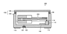
図8は、第2実施形態における物理量検出器100の内部構造を模式的に示す断面図である。物理量検出器100は、第1実施形態における周波数変化型物理量センサー3である物理量検出デバイス200と、電子回路140と、物理量検出デバイス200及び電子回路140を収容するパッケージ102と、を有する。
FIG. 8 is a cross-sectional view schematically showing the internal structure of the
パッケージ102は、パッケージベース104と、リッド106とを有する。パッケージ102は、凹部を有するパッケージベース104の上方を覆うように、板状のリッド106がリッド接合材108を介してパッケージベース104に接続されていることで内部空間を画成しており、この内部空間に、物理量検出デバイス200、及び、電子回路140を支持・固定している。パッケージベース104は、例えば、セラミックス、水晶、ガラス、シリコンなどの材料を用いることができる。リッド106は、例えば、パッケージベース104と同じ材料や、鉄(Fe)とニッケル(Ni)の合金、ステンレス鋼などの金属を用いることができる。リッド接合材108は、例えば、シームリング、低融点ガラス、無機系接着剤を用いることができる。
The
パッケージベース104の内部には、内壁に沿って、その上面に物理量検出デバイス200を支持・固定するための段差部110が設けられている。また、段差部110の上面には、物理量検出デバイス200の固定部接続端子と電気的に接続される内部端子114が設けられている。
Inside the
パッケージベース104の外底面には、外部の部材に実装される際に用いられる外部端子116が設けられている。外部端子116は、図示しない内部配線を介して内部端子114と電気的に接続されている。内部端子114及び外部端子116は、例えば、タングステン(W)等のメタライズ層に、ニッケル(Ni)、金(Au)などの皮膜をメッキなどの方法により積層した金属膜で構成されている。
パッケージベース104の底部には、外底面から内底面まで貫通する貫通孔120が形成されている。図8に示す例では、貫通孔120は、外側の孔径が内側の孔径よりも大きい段付きの形状をしている。この貫通孔120内には、パッケージ102の内部(キャビティー)を気密に封止するための封止部122が設けられている。封止部122は、貫通孔120に、例えば、金(Au)とゲルマニウム(Ge)の合金、ハンダ等からなる封止材を配置し、加熱溶融後、固化させることで設けられる。リッド106をパッケージベース104に接合した後、パッケージ102の内部が減圧された状態(真空度の高い状態)で貫通孔120内に封止材を配置し、加熱溶融後、固化させて封止部122を設けることによって、パッケージ102内を気密に封止することができる。パッケージ102の内部は、窒素、ヘリウム、アルゴンなどの不活性ガスが充填されていて良い。
A through
電子回路140は、内部端子114等を経由して、物理量検出デバイス200に駆動信号を与えるとともに、印加される加速度等の物理量に応じて変化する物理量検出デバイス200から出力される供給周波数を増幅し、外部端子116から物理量検出器100の外部に出力する。また、この電子回路140に、第1実施形態における周波数比測定装置7や基準信号発振部5等が実装される。
The
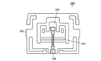
図9,図10は、物理量検出デバイス200を模式的に示す斜視図である。図10は、説明の簡明化のために、質量部210の図示を省略したものである。また、図11は、物理量検出デバイス200の平面図である。物理量検出デバイス200は、四方を支持部で支持された基部202と、基部202より延設された継手部204で連結されて検出方向の加速度によってしなる可動部206と、物理量検出素子208と、を有する。
9 and 10 are perspective views schematically showing the physical
物理量検出素子208は、例えば、水晶原石等から所定の角度で切り出された水晶基板を、フォトリソグラフィー技術、及びエッチング技術によってパターニングすることにより形成されている双音叉型の振動素子である。勿論、当該素子の素材は水晶に限らず、タンタル酸リチウム、四ホウ酸リチウム、ニオブ酸リチウム、チタン酸ジルコン酸鉛、酸化亜鉛、窒化アルミニウム等の圧電材料を用いることができる。また、酸化亜鉛、窒化アルミニウムなどの圧電材料皮膜を備えたシリコンなどの半導体材料を用いることができる。
The physical
物理量検出素子208は、継手部204を跨ぐようにした梁状に形成されており、その梁部の一端側が基部202に、他端側が可動部206に固定されている。物理量検出素子208の両端部には、信号線(図示略)が接続されて所定の電流電圧が印加されており、物理量検出素子208が所定周波数で振動するように構成されている。そして、測定方向に生じた加速度によって可動部206がしなることで物理量検出素子208の梁部に応力が作用すると、物理量検出素子208の振動周波数が変化する。この振動周波数の変化に基づいて加速度に応じた信号が生成されて、物理量検出素子208の出力信号として出力される。
The physical
[第3実施形態]
次に、第3実施形態を説明する。以降では、第1及び第2実施形態との差異について主に述べることとし、第1及び第2実施形態と同様の構成要素については同じ符号を付与して重複する説明を省略する。第3実施形態は、第2実施形態における物理量検出器100を用いた加速度物理量センサーの実施形態である。
[Third Embodiment]
Next, a third embodiment will be described. In the following, differences from the first and second embodiments will be mainly described, and the same components as those in the first and second embodiments will be assigned the same reference numerals and redundant description will be omitted. The third embodiment is an embodiment of an acceleration physical quantity sensor using the
図12は、第3実施形態における加速度物理量センサー300の内部構造を模式的に示す断面図である。加速度物理量センサー300は、電子回路基板310と、電子回路基板310を収容する収容部320と、を有する。
FIG. 12 is a cross-sectional view schematically showing the internal structure of the acceleration
収容部320は、下部アウターケース322の上方に、下方に開口する上部アウターケース324を被せて密封することで内部空間を画成している。そして、収容部320は、当該内部空間にて、インナーケース326やパッキン328を介して電子回路基板310を支持・固定している。
The
電子回路基板310は、同じ仕様の3つの第2実施形態の物理量検出器100(100x,100y,100z)や、各物理量検出器100(100x,100y,100z)の出力信号を増幅する増幅回路等を実装している。
The
電子回路基板310に実装されている3つの物理量検出器100x,100y,100zは、物理量である加速度を検出する物理量センサーであり、検出方向について検出した加速度に応じた信号を出力する。また、3つの物理量検出器100x,100y,100zは、互いに検出方向が直交するように実装されており、加速度物理量センサー300は、直交3軸方向の加速度を検出する、いわゆる3軸加速度物理量センサーとなっている。
The three
[第4実施形態]
次に、第4実施形態を説明する。以降では、第1乃至第3実施形態との差異について主に述べることとし、第1乃至第3実施形態と同様の構成要素については同じ符号を付与して重複する説明を省略する。第4実施形態は、第3実施形態の加速度物理量センサー300を用いた傾斜計の実施形態である。
[Fourth Embodiment]
Next, a fourth embodiment will be described. In the following, differences from the first to third embodiments will be mainly described, and the same components as those in the first to third embodiments will be assigned the same reference numerals and redundant description will be omitted. The fourth embodiment is an embodiment of an inclinometer using the acceleration
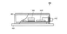
図13は、第4実施形態における傾斜計400の構成例を示す図であって、一部断面表示された側面図である。傾斜計400は、設置された位置の傾斜角度に応じた信号を出力する装置である。傾斜計400は、アンダーケース402とアッパーケース404とで画成された内部空間に、第3実施形態の加速度物理量センサー300と、加速度物理量センサー300の出力信号に基づいて傾斜角度を算出する算出部410と、算出部410で算出された傾斜角度に応じた信号を外部出力する外部出力端子412と、を有する。勿論、これ以外の要素を適宜含めることができる。例えば、内蔵バッテリーや電源回路、無線装置、等を含めることができる。
FIG. 13 is a diagram illustrating a configuration example of the
算出部410は、加速度物理量センサー300の出力信号から傾斜角度を演算して、傾斜角度に応じた信号を出力する回路である。例えば、汎用IC(Integrated Circuit)やFPGA(Field Programmable Gate Array)などにより実現することができる。
The
第4実施形態の傾斜計400によれば、第1実施形態の物理量センサーモジュール1を用いた加速度物理量センサー300を採用しているため、傾斜の計測精度を従来の傾斜計よりも向上させることができる。
According to the
[第5実施形態]
次に、第5実施形態を説明する。以降では、第1乃至第4実施形態との差異について主に述べることとし、第1乃至第4実施形態と同様の構成要素については同じ符号を付与して重複する説明を省略する。第5実施形態は、第3実施形態の加速度物理量センサー300を用いた慣性計測装置の実施形態である。
[Fifth Embodiment]
Next, a fifth embodiment will be described. In the following, differences from the first to fourth embodiments will be mainly described, and the same components as those in the first to fourth embodiments will be assigned the same reference numerals and redundant description will be omitted. The fifth embodiment is an embodiment of an inertial measurement device using the acceleration
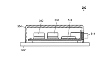
図14は、第5実施形態における慣性計測装置500の構成例を示す図であって、一部断面表示された側面図である。慣性計測装置500は、移動体に取り付けられる装置であって、アンダーケース502とアッパーケース504とで画成された内部空間に、第3実施形態の加速度物理量センサー300と、角速度物理量センサー510と、加速度物理量センサー300の出力信号及び角速度物理量センサー510の出力信号に基づいて移動体の姿勢を算出する回路部512と、回路部512で算出された姿勢に応じた信号を外部出力する外部出力端子514と、を有する。勿論、これ以外の要素を適宜含めることができる。例えば、内蔵バッテリーや電源回路、無線装置、等を含めることができる。
FIG. 14 is a diagram illustrating a configuration example of the
角速度物理量センサー510は、基本的には、加速度物理量センサー300と同様の構成を有し、X軸、Y軸及びZ軸の各軸回りの角速度を検出する、いわゆる3軸角速度物理量センサーである。
The angular velocity
回路部512は、例えば、汎用IC(Integrated Circuit)やFPGA(Field Programmable Gate Array)により実現され、加速度物理量センサー300の出力信号と、角速度物理量センサー510の出力信号とから、慣性計測装置500が取り付けられている移動体の姿勢を算出し、姿勢に応じた信号を出力する。
The
[第6実施形態]
次に、第6実施形態を説明する。以降では、第1乃至第5実施形態との差異について主に述べることとし、第1乃至第5実施形態と同様の構成要素については同じ符号を付与して重複する説明を省略する。第6実施形態は、第3実施形態における加速度物理量センサー300を用いた構造物監視装置の実施形態である。
[Sixth Embodiment]
Next, a sixth embodiment will be described. Hereinafter, differences from the first to fifth embodiments will be mainly described, and the same components as those in the first to fifth embodiments are denoted by the same reference numerals, and redundant description will be omitted. The sixth embodiment is an embodiment of a structure monitoring apparatus using the acceleration
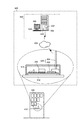
図15は、第6実施形態における構造物監視装置600の構成例を示す図である。構造物監視装置600は、監視対象とされる構造物690に取り付けられる第3実施形態の加速度物理量センサー300と、加速度物理量センサー300の検出信号を送信する送信部620と、通信網650を介して送信部620からの送信信号を受信する受信部636と、受信部636の受信信号に基づいて構造物690の傾斜角度を算出する算出部632と、を有する。通信網650は、有線・無線の何れであっても良い。
FIG. 15 is a diagram illustrating a configuration example of a
加速度物理量センサーユニット610は、アンダーケース612とアッパーケース614とで画成される内部空間に、第3実施形態の加速度物理量センサー300と、小型の通信端末としての機能を実現する通信モジュール622及びアンテナ644を含む送信部620と、を搭載して構成されている。勿論、送信部620は、加速度物理量センサー300とは別体の通信モジュール及びアンテナとして実現するとしても良い。
The acceleration physical
算出部632は、本実施形態では、監視コンピューター630に搭載されたASIC(Application Specific Integrated Circuit)やFPGA(Field Programmable Gate Array)等で実現することとする。但し、算出部632をCPU(Central Processing Unit)等のプロセッサーとして、当該プロセッサーがICメモリー634に記憶されたプログラムを演算処理することによりソフトウェア的に実現する構成としてもよい。監視コンピューター630は、キーボード638によりオペレーターの各種操作入力を受け付け、演算処理の結果をタッチパネル640に表示することができる。
In this embodiment, the
受信部636は、通信網650に接続する有線通信装置或いは無線通信装置によって実現される。本実施形態では、送信部620と無線通信する通信モジュール及びアンテナによって実現するが、監視コンピューター630とは別体の通信モジュール及びアンテナとして実現するとしてもよい。
The receiving
[第7実施形態]
次に、第7実施形態を説明する。以降では、第1乃至第6実施形態との差異について主に述べることとし、第1乃至第6実施形態と同様の構成要素については同じ符号を付与して重複する説明を省略する。第7実施形態は、第3実施形態の加速度物理量センサー300を用いた移動体の実施形態である。
[Seventh Embodiment]
Next, a seventh embodiment will be described. In the following, differences from the first to sixth embodiments will be mainly described, and the same components as those in the first to sixth embodiments will be assigned the same reference numerals and redundant description will be omitted. The seventh embodiment is an embodiment of a moving object using the acceleration
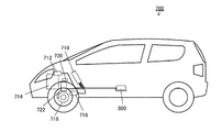
図16は、第7実施形態における移動体700の構成例を示す図である。本実施形態では、移動体700を乗用車として例示するが、車種は適宜変更可能である。また、移動体700は、小型船舶や自動運搬装置、構内用の運搬車、フォークリフトなどでも良い。
FIG. 16 is a diagram illustrating a configuration example of the moving
移動体700は、第3実施形態の加速度物理量センサー300と、加速度物理量センサー300の検出信号に基づいて、加速、制動及び操舵のうちの少なくとも1つを制御する制御部710とを有し、自動運転の実施或いは不実施を、加速度物理量センサー300の検出信号に基づいて切り替えることができる。
The moving
制御部710は、車載用のコンピューターによって実現される。制御部710は、車内LAN(Local Area Network)等の通信網によって、加速度物理量センサー300、スロットルコントローラー712、ブレーキコントローラー716、ステアリングコントローラー720、などの各種物理量センサー及コントローラーと信号送受可能に接続されている。ここで、スロットルコントローラー712は、エンジン714の出力を制御する装置である。ブレーキコントローラー716は、ブレーキ718の作動を制御する装置である。ステアリングコントローラー720は、パワーステアリング722の作動を制御する装置である。なお、制御部710に接続される物理量センサーコントローラーの種類はこれに限らず適宜設定できる。
The
そして、制御部710は、内蔵する演算装置で、加速度物理量センサー300の検出信号に基づいて演算処理を行って、自動運転の実施或いは不実施を判定し、自動運転を実施する場合には、スロットルコントローラー712、ブレーキコントローラー716、ステアリングコントローラー720の少なくとも何れか1つに制御指令信号を送信して、加速、制動及び操舵のうちの少なくとも1つを制御する。
The
自動制御の内容は、適宜設定可能である。例えば、コーナリング中に、加速度物理量センサー300で検出される加速度が、スピンやコーナーアウトを生じる恐れが高いとされる閾値に達した場合に、スピンやコーナーアウトを防止するような制御を行うとしてもよい。また、停止中に、加速度物理量センサー300で検出される加速度が、操作を誤って急激な前進又は後進が生じた可能性が高いとされる閾値に達した場合に、スロットルを強制全閉させて急ブレーキを強制発動させるような制御を行うとしてもよい。
The contents of automatic control can be set as appropriate. For example, when the acceleration detected by the acceleration
なお、本発明の適用可能な実施形態は上述の実施形態に限定されることなく、本発明の趣旨を逸脱しない範囲で適宜変更可能なのは勿論である。 It should be noted that embodiments to which the present invention can be applied are not limited to the above-described embodiments, and can of course be changed as appropriate without departing from the spirit of the present invention.
1…物理量センサーモジュール、3…周波数変化型物理量センサー、5…基準信号発振部、7…周波数比測定装置、10…周波数デルタシグマ変調部、20…第1ローパスフィルター、50…第3ラッチ、60…第2ローパスフィルター、100…物理量検出器、200…物理量検出デバイス、300…加速度物理量センサー、400…傾斜計、500…慣性航法装置、600…構造物監視装置、700…移動体
DESCRIPTION OF
Claims (12)
基準信号を出力する基準信号発振部と、
前記周波数変化型物理量センサーから出力された被測定信号に基づく動作信号を用いて、前記基準信号を周波数デルタシグマ変調し、周波数デルタシグマ変調信号を生成する周波数デルタシグマ変調部と、
前記周波数デルタシグマ変調部の出力側に設けられ、前記被測定信号に同期して動作する第1のフィルターと、
前記第1のフィルターの出力側に設けられ、前記基準信号に同期して動作する第2のフィルターと、
を備えている物理量センサーモジュール。 A frequency change type physical quantity sensor whose frequency changes in accordance with a change in physical quantity,
A reference signal oscillator for outputting a reference signal;
A frequency delta sigma modulation unit that generates a frequency delta sigma modulation signal by performing frequency delta sigma modulation on the reference signal using an operation signal based on a signal under measurement output from the frequency change physical quantity sensor;
A first filter provided on an output side of the frequency delta-sigma modulation unit and operating in synchronization with the signal under measurement;
A second filter provided on the output side of the first filter and operating in synchronization with the reference signal;
Physical quantity sensor module equipped with.
前記第1のフィルター及び前記第2のフィルターの合成により実現されるフィルター特性であるカットオフ周波数が、前記周波数変化型物理量センサーの構造共振周波数よりも低い、
物理量センサーモジュール。 In claim 1,
A cutoff frequency, which is a filter characteristic realized by the synthesis of the first filter and the second filter, is lower than a structural resonance frequency of the frequency change type physical quantity sensor;
Physical quantity sensor module.
前記構造共振周波数は、前記周波数変化型物理量センサーの構造に基づいて決まる周波数である、
物理量センサーモジュール。 In claim 2,
The structural resonance frequency is a frequency determined based on the structure of the frequency change type physical quantity sensor.
Physical quantity sensor module.
前記周波数変化型物理量センサーは、前記物理量に対する出力信号の特性として非線形性を有しており、
前記第1のフィルターは、入出力特性が、前記周波数変化型物理量センサーの出力である被測定信号の非線形性を線形に近づけるための特性に設定された、
物理量センサーモジュール。 In any one of Claims 1 thru | or 3,
The frequency change type physical quantity sensor has nonlinearity as a characteristic of an output signal with respect to the physical quantity,
In the first filter, the input / output characteristic is set to a characteristic for making the nonlinearity of the signal under measurement, which is the output of the frequency-variable physical quantity sensor close to a linearity,
Physical quantity sensor module.
前記第1のフィルターは、フィルタータップ数によって平滑化タイミングを変更可能な平滑化フィルターであり、前記フィルタータップ数が、前記非線形性によって現れる前記周波数変化型物理量センサーの出力である被測定信号の振動整流誤差を低減させる平滑化タイミングに設定された、
物理量センサーモジュール。 In claim 4,
The first filter is a smoothing filter whose smoothing timing can be changed according to the number of filter taps, and the number of filter taps is an output of the frequency-variable physical quantity sensor that appears due to the nonlinearity. Set to smoothing timing to reduce rectification error,
Physical quantity sensor module.
前記フィルタータップ数は、外部から設定変更可能である、
物理量センサーモジュール。 In claim 5,
The number of filter taps can be changed from the outside.
Physical quantity sensor module.
前記第1のフィルターは、前記平滑化タイミングの変更量の粗密が異なる複数のフィルタータップ数で前記平滑タイミングを変更可能である、
物理量センサーモジュール。 In claim 5 or 6,
The first filter is capable of changing the smoothing timing with a plurality of filter tap numbers having different coarse and dense change amounts of the smoothing timing.
Physical quantity sensor module.
前記物理量は加速度である、
物理量センサーモジュール。 In any of claims 1 to 5,
The physical quantity is acceleration.
Physical quantity sensor module.
前記物理量センサーモジュールの出力信号に基づいて傾斜角度を算出する算出部と、
を具備した傾斜計。 The physical quantity sensor module according to claim 8,
A calculation unit that calculates an inclination angle based on an output signal of the physical quantity sensor module;
Inclinometer equipped with.
請求項8に記載の物理量センサーモジュールと、
角速度物理量センサーモジュールと、
前記物理量センサーモジュールの出力と前記角速度物理量センサーモジュールの出力とに基づいて前記移動体の姿勢を算出する回路部と、
を具備した慣性計測装置。 An inertial measurement device attached to a moving body,
The physical quantity sensor module according to claim 8,
Angular velocity physical quantity sensor module,
A circuit unit that calculates an attitude of the moving body based on an output of the physical quantity sensor module and an output of the angular velocity physical quantity sensor module;
An inertial measurement device.
前記構造物に取り付けられ、前記物理量センサーモジュールの出力を送信する送信部と、
前記送信部からの送信信号を受信する受信部と、
前記受信部の受信信号に基づいて前記構造物の傾斜角度を算出する算出部と、
を具備した構造物監視装置。 The physical quantity sensor module according to claim 8 attached to a structure;
A transmission unit attached to the structure and transmitting the output of the physical quantity sensor module;
A receiver for receiving a transmission signal from the transmitter;
A calculation unit that calculates an inclination angle of the structure based on a reception signal of the reception unit;
A structure monitoring apparatus comprising:
前記物理量センサーモジュールの出力信号に基づいて、加速、制動および操舵のうちの少なくとも1つを制御する制御部と、
を具備し、
自動運転の実施或いは不実施を、前記物理量センサーモジュールの出力に基づいて切り替える、
移動体。 The physical quantity sensor module according to claim 8,
A control unit that controls at least one of acceleration, braking, and steering based on an output signal of the physical quantity sensor module;
Comprising
Switching between automatic operation and non-operation based on the output of the physical quantity sensor module,
Moving body.
Priority Applications (5)
| Application Number | Priority Date | Filing Date | Title |
|---|---|---|---|
| JP2018081177A JP7040253B2 (en) | 2018-04-20 | 2018-04-20 | Physical quantity sensor module, inclinometer, inertial measurement unit, structure monitoring device, and moving object |
| CN201910316383.6A CN110388907B (en) | 2018-04-20 | 2019-04-19 | Physical quantity sensor unit, inclinometer, and structure monitoring device |
| CN202310835489.3A CN116817879A (en) | 2018-04-20 | 2019-04-19 | Physical quantity sensor unit, inclinometer, and structure monitoring device |
| US16/389,098 US11079403B2 (en) | 2018-04-20 | 2019-04-19 | Physical quantity sensor module, clinometer, and structure monitoring device |
| US17/364,934 US11733262B2 (en) | 2018-04-20 | 2021-07-01 | Physical quantity sensor module, clinometer, and structure monitoring device |
Applications Claiming Priority (1)
| Application Number | Priority Date | Filing Date | Title |
|---|---|---|---|
| JP2018081177A JP7040253B2 (en) | 2018-04-20 | 2018-04-20 | Physical quantity sensor module, inclinometer, inertial measurement unit, structure monitoring device, and moving object |
Publications (2)
| Publication Number | Publication Date |
|---|---|
| JP2019190897A true JP2019190897A (en) | 2019-10-31 |
| JP7040253B2 JP7040253B2 (en) | 2022-03-23 |
Family
ID=68237641
Family Applications (1)
| Application Number | Title | Priority Date | Filing Date |
|---|---|---|---|
| JP2018081177A Active JP7040253B2 (en) | 2018-04-20 | 2018-04-20 | Physical quantity sensor module, inclinometer, inertial measurement unit, structure monitoring device, and moving object |
Country Status (3)
| Country | Link |
|---|---|
| US (2) | US11079403B2 (en) |
| JP (1) | JP7040253B2 (en) |
| CN (2) | CN110388907B (en) |
Cited By (4)
| Publication number | Priority date | Publication date | Assignee | Title |
|---|---|---|---|---|
| JP2022104345A (en) * | 2020-12-28 | 2022-07-08 | セイコーエプソン株式会社 | Vibration rectification error correction device, sensor module, and vibration rectification error correction method |
| JP2023175165A (en) * | 2022-05-30 | 2023-12-12 | セイコーエプソン株式会社 | Inertial measurement device and self-diagnosis method for inertial measurement device |
| US12000858B2 (en) | 2020-12-28 | 2024-06-04 | Seiko Epson Corporation | Vibration rectification error correction device, sensor module, and vibration rectification error correction method |
| US12241908B2 (en) | 2021-11-29 | 2025-03-04 | Seiko Epson Corporation | Vibration rectification error correction device, sensor module, and vibration rectification error correction method |
Families Citing this family (4)
| Publication number | Priority date | Publication date | Assignee | Title |
|---|---|---|---|---|
| JP7040253B2 (en) * | 2018-04-20 | 2022-03-23 | セイコーエプソン株式会社 | Physical quantity sensor module, inclinometer, inertial measurement unit, structure monitoring device, and moving object |
| JP7615677B2 (en) * | 2020-12-28 | 2025-01-17 | セイコーエプソン株式会社 | Signal processing method, signal processing device, physical quantity measuring device, and sensor module |
| JP7797885B2 (en) * | 2022-01-18 | 2026-01-14 | セイコーエプソン株式会社 | Diagnostic method, diagnostic device, and diagnostic system |
| KR102716661B1 (en) * | 2024-05-23 | 2024-10-15 | 주식회사 피두키아 | Apparatus for detecting photochemical reaction |
Citations (4)
| Publication number | Priority date | Publication date | Assignee | Title |
|---|---|---|---|---|
| US5165279A (en) * | 1989-07-06 | 1992-11-24 | Sundstrand Corporation | Monolithic accelerometer with flexurally mounted force transducer |
| JP2009236899A (en) * | 2008-03-27 | 2009-10-15 | Honeywell Internatl Inc | Vibrating beam accelerometer with improved performance in vibration environment |
| JP2009250807A (en) * | 2008-04-07 | 2009-10-29 | Seiko Epson Corp | Frequency measurement device and measurement method |
| JP2017120209A (en) * | 2015-12-28 | 2017-07-06 | セイコーエプソン株式会社 | Physical quantity detection device, measurement system, and measurement device |
Family Cites Families (12)
| Publication number | Priority date | Publication date | Assignee | Title |
|---|---|---|---|---|
| US5459432A (en) * | 1993-07-22 | 1995-10-17 | Rockwell International Corporation | Use of a chopper and a sigma-delta modulator for downconverting and digitizing an analog signal including information modulated by a carrier |
| JPH07120498A (en) | 1993-10-25 | 1995-05-12 | Hitachi Ltd | Characteristic adjustment method for capacitance type acceleration sensor |
| JPH0933563A (en) | 1995-07-19 | 1997-02-07 | Sumitomo Precision Prod Co Ltd | Capacitive sensor |
| US7131315B2 (en) | 2004-09-28 | 2006-11-07 | Honeywell International Inc. | Methods and apparatus for reducing vibration rectification errors in closed-loop accelerometers |
| DE102006055589B4 (en) * | 2006-11-24 | 2012-07-19 | Infineon Technologies Ag | Measuring device and measured value sensor with coupled processing and excitation frequency |
| JP2011064515A (en) * | 2009-09-16 | 2011-03-31 | Hitachi Automotive Systems Ltd | Angular speed and acceleration detector |
| JP2011080911A (en) * | 2009-10-08 | 2011-04-21 | Seiko Epson Corp | Frequency measurement device and electronic apparatus equipped with the frequency measurement device |
| CN102809671B (en) * | 2012-08-20 | 2014-07-30 | 中国兵器工业集团第二一四研究所苏州研发中心 | Single chip closed loop integrated circuit of acceleration transducer |
| JP6331365B2 (en) * | 2013-12-05 | 2018-05-30 | セイコーエプソン株式会社 | Detection device, sensor, electronic device, and moving object |
| JP6589333B2 (en) * | 2015-03-30 | 2019-10-16 | セイコーエプソン株式会社 | Circuit device, electronic device and moving body |
| DE102016204683B3 (en) * | 2016-03-22 | 2017-07-13 | Albert-Ludwigs-Universität Freiburg | METHOD FOR THE AUTOMATIC FREQUENCY ADAPTATION OF FILTERS DURING OPERATION IN CLOSED CONTROL GRINDING |
| JP7040253B2 (en) * | 2018-04-20 | 2022-03-23 | セイコーエプソン株式会社 | Physical quantity sensor module, inclinometer, inertial measurement unit, structure monitoring device, and moving object |
-
2018
- 2018-04-20 JP JP2018081177A patent/JP7040253B2/en active Active
-
2019
- 2019-04-19 CN CN201910316383.6A patent/CN110388907B/en active Active
- 2019-04-19 US US16/389,098 patent/US11079403B2/en active Active
- 2019-04-19 CN CN202310835489.3A patent/CN116817879A/en active Pending
-
2021
- 2021-07-01 US US17/364,934 patent/US11733262B2/en active Active
Patent Citations (4)
| Publication number | Priority date | Publication date | Assignee | Title |
|---|---|---|---|---|
| US5165279A (en) * | 1989-07-06 | 1992-11-24 | Sundstrand Corporation | Monolithic accelerometer with flexurally mounted force transducer |
| JP2009236899A (en) * | 2008-03-27 | 2009-10-15 | Honeywell Internatl Inc | Vibrating beam accelerometer with improved performance in vibration environment |
| JP2009250807A (en) * | 2008-04-07 | 2009-10-29 | Seiko Epson Corp | Frequency measurement device and measurement method |
| JP2017120209A (en) * | 2015-12-28 | 2017-07-06 | セイコーエプソン株式会社 | Physical quantity detection device, measurement system, and measurement device |
Cited By (7)
| Publication number | Priority date | Publication date | Assignee | Title |
|---|---|---|---|---|
| JP2022104345A (en) * | 2020-12-28 | 2022-07-08 | セイコーエプソン株式会社 | Vibration rectification error correction device, sensor module, and vibration rectification error correction method |
| US11988685B2 (en) | 2020-12-28 | 2024-05-21 | Seiko Epson Corporation | Vibration rectification error correction device, sensor module, and vibration rectification error correction method |
| US12000858B2 (en) | 2020-12-28 | 2024-06-04 | Seiko Epson Corporation | Vibration rectification error correction device, sensor module, and vibration rectification error correction method |
| JP7635550B2 (en) | 2020-12-28 | 2025-02-26 | セイコーエプソン株式会社 | Vibration rectification error correction device, sensor module, and vibration rectification error correction method |
| US12276673B2 (en) | 2020-12-28 | 2025-04-15 | Seiko Epson Corporation | Vibration rectification error correction device, sensor module, and vibration rectification error correction method |
| US12241908B2 (en) | 2021-11-29 | 2025-03-04 | Seiko Epson Corporation | Vibration rectification error correction device, sensor module, and vibration rectification error correction method |
| JP2023175165A (en) * | 2022-05-30 | 2023-12-12 | セイコーエプソン株式会社 | Inertial measurement device and self-diagnosis method for inertial measurement device |
Also Published As
| Publication number | Publication date |
|---|---|
| US11733262B2 (en) | 2023-08-22 |
| CN110388907B (en) | 2023-06-30 |
| US20190324052A1 (en) | 2019-10-24 |
| CN110388907A (en) | 2019-10-29 |
| JP7040253B2 (en) | 2022-03-23 |
| US20210325424A1 (en) | 2021-10-21 |
| US11079403B2 (en) | 2021-08-03 |
| CN116817879A (en) | 2023-09-29 |
Similar Documents
| Publication | Publication Date | Title |
|---|---|---|
| JP7040253B2 (en) | Physical quantity sensor module, inclinometer, inertial measurement unit, structure monitoring device, and moving object | |
| US9030082B2 (en) | Vibrator element, sensor unit, electronic apparatus, manufacturing method of vibrator element, and manufacturing method of sensor unit | |
| US11808572B2 (en) | Vibration rectification error correction circuit, physical quantity sensor module, structure monitoring device, and correction value adjustment method of vibration rectification error correction circuit | |
| EP2107337B1 (en) | Angular velocity measuring device | |
| US11133815B2 (en) | Resampling circuit, physical quantity sensor unit, inertial measurement unit, and structure monitoring device | |
| JP5013250B2 (en) | Acceleration sensor | |
| EP3385669A1 (en) | Circuit device, physical quantity measurement device, electronic device, and vehicle | |
| US11187716B2 (en) | Resampling circuit, physical quantity sensor unit, inertial measurement unit, and structure monitoring device | |
| US11095302B2 (en) | Frequency delta sigma modulation signal output circuit, physical quantity sensor module, and structure monitoring device | |
| JP2012159429A (en) | Tuning fork vibration type angular velocity sensor | |
| US9279826B2 (en) | Inertial force sensor with a correction unit | |
| JP7069968B2 (en) | Circuit equipment and physical quantity measuring equipment using it, oscillators, electronic devices and mobile objects | |
| JP2023087215A (en) | Frequency delta-sigma modulation signal output circuit and sensor module | |
| JP2009186285A (en) | Acceleration sensor |
Legal Events
| Date | Code | Title | Description |
|---|---|---|---|
| A621 | Written request for application examination |
Free format text: JAPANESE INTERMEDIATE CODE: A621 Effective date: 20210315 |
|
| A977 | Report on retrieval |
Free format text: JAPANESE INTERMEDIATE CODE: A971007 Effective date: 20220114 |
|
| TRDD | Decision of grant or rejection written | ||
| A01 | Written decision to grant a patent or to grant a registration (utility model) |
Free format text: JAPANESE INTERMEDIATE CODE: A01 Effective date: 20220208 |
|
| A61 | First payment of annual fees (during grant procedure) |
Free format text: JAPANESE INTERMEDIATE CODE: A61 Effective date: 20220221 |
|
| R150 | Certificate of patent or registration of utility model |
Ref document number: 7040253 Country of ref document: JP Free format text: JAPANESE INTERMEDIATE CODE: R150 |