JP2019192570A - Fuel cell separator - Google Patents
Fuel cell separator Download PDFInfo
- Publication number
- JP2019192570A JP2019192570A JP2018086376A JP2018086376A JP2019192570A JP 2019192570 A JP2019192570 A JP 2019192570A JP 2018086376 A JP2018086376 A JP 2018086376A JP 2018086376 A JP2018086376 A JP 2018086376A JP 2019192570 A JP2019192570 A JP 2019192570A
- Authority
- JP
- Japan
- Prior art keywords
- separator
- fuel cell
- metal oxide
- film
- conductive film
- Prior art date
- Legal status (The legal status is an assumption and is not a legal conclusion. Google has not performed a legal analysis and makes no representation as to the accuracy of the status listed.)
- Granted
Links
Images
Classifications
-
- Y—GENERAL TAGGING OF NEW TECHNOLOGICAL DEVELOPMENTS; GENERAL TAGGING OF CROSS-SECTIONAL TECHNOLOGIES SPANNING OVER SEVERAL SECTIONS OF THE IPC; TECHNICAL SUBJECTS COVERED BY FORMER USPC CROSS-REFERENCE ART COLLECTIONS [XRACs] AND DIGESTS
- Y02—TECHNOLOGIES OR APPLICATIONS FOR MITIGATION OR ADAPTATION AGAINST CLIMATE CHANGE
- Y02E—REDUCTION OF GREENHOUSE GAS [GHG] EMISSIONS, RELATED TO ENERGY GENERATION, TRANSMISSION OR DISTRIBUTION
- Y02E60/00—Enabling technologies; Technologies with a potential or indirect contribution to GHG emissions mitigation
- Y02E60/30—Hydrogen technology
- Y02E60/50—Fuel cells
Landscapes
- Fuel Cell (AREA)
Abstract
【課題】耐食性を確保しつつ、導電性の悪化を防止することができる燃料電池用セパレータを提供する。
【解決手段】燃料電池用セパレータ3は、金属製のセパレータ基材31と、セパレータ基材31の表面に形成され、導電率が100S/cm以上の金属酸化物32と、金属酸化物32の表面に形成され、膜厚が30nm以上の導電性皮膜33と、を備えている。
【選択図】図2Provided is a fuel cell separator capable of preventing deterioration of conductivity while ensuring corrosion resistance.
A fuel cell separator 3 is formed on a surface of a separator base 31 made of metal, a metal oxide 32 having a conductivity of 100 S / cm or more, and a surface of the metal oxide 32. And a conductive film 33 having a film thickness of 30 nm or more.
[Selection] Figure 2
Description
本発明は、燃料電池用セパレータに関する。 The present invention relates to a fuel cell separator.
従来、このような分野の技術として、例えば特許文献1に記載されるように、金属製のセパレータ基材の表面に導電性皮膜を設けたものが知られている。このような構造を有する燃料電池用セパレータでは、導電性皮膜を設けることにより生成水等の腐食液の浸透を阻止し、耐食性を確保している。
Conventionally, as a technique in such a field, as described in
しかし、この種の燃料電池用セパレータでは、セパレータ基材の表面に導電性皮膜を形成する際にセパレータ基材が酸化してしまい、セパレータ基材と導電性皮膜との間に酸化膜が形成される。これによって、燃料電池用セパレータの電気抵抗が高くなり、導電性の悪化を招く問題が生じる。 However, in this type of fuel cell separator, the separator base material is oxidized when the conductive film is formed on the surface of the separator base material, and an oxide film is formed between the separator base material and the conductive film. The As a result, the electric resistance of the fuel cell separator is increased, resulting in a problem that the conductivity is deteriorated.
本発明は、このような技術課題を解決するためになされたものであって、耐食性を確保しつつ、導電性の悪化を防止することができる燃料電池用セパレータを提供することを目的とする。 The present invention has been made to solve such technical problems, and an object of the present invention is to provide a fuel cell separator capable of preventing deterioration of conductivity while ensuring corrosion resistance.
本発明に係る燃料電池用セパレータは、金属製のセパレータ基材と、前記セパレータ基材の表面に形成され、導電率が100S/cm以上の金属酸化物と、前記金属酸化物の表面に形成され、膜厚が30nm以上の導電性皮膜と、を備えることを特徴としている。 The separator for a fuel cell according to the present invention is formed on a metal separator base, a surface of the separator base, a metal oxide having a conductivity of 100 S / cm or more, and a surface of the metal oxide. And a conductive film having a film thickness of 30 nm or more.
本発明に係る燃料電池用セパレータでは、膜厚が30nm以上の導電性皮膜を備えるので、該導電性皮膜で腐食液の浸透を阻止することにより、耐食性を確保することができる。加えて、セパレータ基材と導電性皮膜との間に導電率が100S/cm以上の金属酸化物が介在されるので、導電性皮膜を形成する際のセパレータ基材の酸化を防ぐことができる。その結果、耐食性を確保しつつ、導電性の悪化を防止することができる。 In the fuel cell separator according to the present invention, the conductive film having a film thickness of 30 nm or more is provided. Therefore, the corrosion resistance can be ensured by preventing the penetration of the corrosive liquid by the conductive film. In addition, since a metal oxide having a conductivity of 100 S / cm or more is interposed between the separator substrate and the conductive film, oxidation of the separator substrate when forming the conductive film can be prevented. As a result, it is possible to prevent deterioration of conductivity while ensuring corrosion resistance.
本発明によれば、耐食性を確保しつつ、導電性の悪化を防止することができる。 According to the present invention, deterioration of conductivity can be prevented while ensuring corrosion resistance.
以下、図面を参照して本発明に係る燃料電池用セパレータの実施形態について説明するが、その前に図1を基に燃料電池用セパレータを備えた燃料電池の構造を簡単に説明する。また、以下の説明において、「燃料電池用セパレータ」を「セパレータ」と略する。 Hereinafter, embodiments of a fuel cell separator according to the present invention will be described with reference to the drawings. Prior to that, a structure of a fuel cell including a fuel cell separator will be briefly described based on FIG. Further, in the following description, “fuel cell separator” is abbreviated as “separator”.
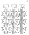
図1は第1実施形態に係る燃料電池用セパレータを備えた燃料電池の要部を示す模式断面図である。図1に示すように、燃料電池10には、基本単位である燃料電池セル1が複数積層されている。燃料電池セル1は、酸化剤ガス(例えば空気)と、燃料ガス(例えば水素ガス)との電気化学反応により起電力を発生する固体高分子型燃料電池セルである。この燃料電池セル1は、MEGA(膜電極ガス拡散層接合体 Membrane Electrode & Gas Diffusion Layer Assembly)2と、MEGA2を挟持する一対のセパレータ3,3とを備えている。
FIG. 1 is a schematic cross-sectional view showing a main part of a fuel cell including a fuel cell separator according to the first embodiment. As shown in FIG. 1, a plurality of
MEGA2は、MEA(膜電極接合体 Membrane Electrode Assembly)4と、MEA4の両面に配置されたガス拡散層7,7とが、一体化されたものである。MEA4は、電解質膜5と、電解質膜5を挟むように接合された一対の電極6,6とからなる。電解質膜5は、固体高分子材料で形成されたプロトン伝導性のイオン交換膜からなる。電極6は、例えば、白金等の触媒を担持した例えば多孔質のカーボン素材により形成されている。電解質膜5の一方側に配置された電極6がアノード電極となり、他方側の電極6がカソード電極となる。ガス拡散層7は、例えばカーボンペーパーもしくはカーボンクロス等のカーボン多孔質体、または、金属メッシュもしくは発泡金属等の金属多孔質体等のガス透過性を有する導電性部材によって形成されている。
The
MEGA2は燃料電池10の発電部を構成しており、セパレータ3はMEGA2のガス拡散層7に接するように配置されている。セパレータ3は、凹部3aと凸部3bとを交互に繰り返すことにより波形に形成されている。凹部3aの底部は平面状を呈しており、MEGA2のガス拡散層7と面接触している。一方、凸部3bの頂部も平面状を呈しており、隣接するセパレータ3における凸部3bの頂部と面接触している。
The MEGA 2 constitutes a power generation unit of the
図1に示すように、一対のガス拡散層7,7のうち一方のガス拡散層7は、それに隣接するセパレータ3の凸部3bとともに、燃料ガスが流通する燃料ガス流路21を画成している。他方のガス拡散層7は、それに隣接するセパレータ3の凸部3bとともに、酸化剤ガスが流通する酸化剤ガス流路22を画成している。
As shown in FIG. 1, one
燃料電池セル1同士は、ある燃料電池セル1のアノード電極6と、それに隣接する他の燃料電池セル1のカソード電極6とを向き合わせた状態で積層されている。これによって、隣接するセパレータ3の凹部3a同士の間には、空間23が形成されている。この空間23は、冷媒が流通する冷媒流路になる。
The
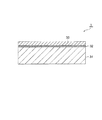
図2は第1実施形態に係る燃料電池用セパレータの構造を示す模式断面図である。図2に示すように、セパレータ3は、金属製のセパレータ基材31と、セパレータ基材31の表面に形成される金属酸化物32と、金属酸化物32の表面に形成される導電性皮膜33とを備えている。セパレータ基材31は、平板状を呈しており、導電性やガス不透過性等に優れたステンレス、チタン、アルミニウム、ニオブ、アンチモン等によって形成されている。
FIG. 2 is a schematic cross-sectional view showing the structure of the fuel cell separator according to the first embodiment. As shown in FIG. 2, the
金属酸化物32は、セパレータ基材31の表面全体にわたって薄膜状に形成されており、その膜厚が2nm以上である。好ましくは、金属酸化物の膜厚は5nm以上である。金属酸化物32の成分として、チタン、スズ、亜鉛、インジウムのうち少なくとも1種類を含んでいる。本実施形態では、金属酸化物32はATO(Antimony doped Tin Oxide、すなわち、Sbをドープした酸化スズ)であり、その導電率は100S/cm以上である。
The
導電性皮膜33は、例えば酸性水溶液に対して優れた耐食性及び浸透バリア性を有する。導電性皮膜33の成分として、少なくとも金属酸化物もしくはカーボンを含んでいる。そして、耐食性の確保及びコスト増加の防止を考慮した場合、導電性皮膜33の膜厚は30nm以上、5000nm以下であることが好ましい。なお、本実施形態では、導電性皮膜33は、例えばカーボンナノチューブ(以下、CNT(Carbon nanotube)という)とSi系バインダーとが含まれるように形成されている。
The
以上の構成を有するセパレータ3は、例えば以下の製造方法によって作製される。すなわち、板状のセパレータ基材31を用意し、酸化雰囲気もしくは塩素雰囲気においてセパレータ基材31の表面にPVD(物理蒸着)法で金属酸化物32を成膜する。その後、金属酸化物32の表面にスプレー法、浸漬法もしくはCVD(化学蒸着)法で導電性皮膜33を成膜する。
The
本実施形態のセパレータ3では、膜厚が30nm以上の導電性皮膜33を備えるので、該導電性皮膜33で生成水等の腐食液の浸透を阻止することにより、セパレータ3の耐食性を確保することができる。加えて、セパレータ基材31と導電性皮膜33との間に導電率が100S/cm以上の金属酸化物32が介在されるので、導電性皮膜33を形成する際のセパレータ基材31の酸化を防ぐことができる。その結果、セパレータ3の耐食性を確保しつつ、導電性の悪化を防止することができる。
In the
なお、本実施形態において、平板状のセパレータ基材31の2つの主面のうち片面に金属酸化物32及び導電性皮膜33が形成された例(図2参照)を説明したが、必要応じてセパレータ基材31の主面の双方に金属酸化物32及び導電性皮膜33を形成しても良い。また、本実施形態において、金属酸化物32として導電率が100S/cm以上のATOを説明したが、ATOのほかにITO(Indium doped Tin Oxide、すなわち、Snをドープした酸化インジウム)を用いても良い。例えば、金属酸化物32は導電率が1000〜10000S/cmのITOからなっても良い。
In addition, in this embodiment, although the example (refer FIG. 2) in which the
<第2実施形態>
図3は第2実施形態に係る燃料電池用セパレータの構造を示す模式断面図である。本実施形態のセパレータ3Aは、金属酸化物32Aの形成範囲において第1実施形態と異なっている。その他の構成は第1実施形態と同様であるので、その重複説明を省略する。
Second Embodiment
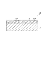
FIG. 3 is a schematic cross-sectional view showing the structure of the fuel cell separator according to the second embodiment. The
具体的には、図3に示すように、金属酸化物32Aは、セパレータ基材31の表面全体にわたって形成されておらず、アイランド状に形成されている。このように構成されたセパレータ3Aは、第1実施形態と同様な作用効果を得られるほか、金属酸化物32Aがセパレータ基材31の表面にアイランド状に形成されているので、セパレータ基材31の表面全体に形成される場合と比べてコスト削減を期待できる。
Specifically, as shown in FIG. 3, the
以下、本発明を実施例により説明するが、本発明は実施例の範囲に限定されるものではない。 EXAMPLES Hereinafter, although an Example demonstrates this invention, this invention is not limited to the range of an Example.
<実施例1〜4>
実施例1〜4では、第1実施形態のセパレータ3を基に、表1に示す諸条件を有する各サンプルを以下の製造方法で作製し、作製した各サンプルに導電性及び耐食性の評価を実施した。
<Examples 1-4>
In Examples 1 to 4, based on the
具体的には、セパレータ基材としてSUS447板(厚さ0.1mm)を用意し、該セパレータ基材の表面にスパッタ法でATOからなる金属酸化物を形成した。ATOに導電率が100S/cmのものを用い、ATOの膜厚は表1に記載の通りであった。 Specifically, a SUS447 plate (thickness 0.1 mm) was prepared as a separator substrate, and a metal oxide made of ATO was formed on the surface of the separator substrate by sputtering. ATO having a conductivity of 100 S / cm was used, and the thickness of ATO was as shown in Table 1.
また、導電性皮膜として、実施例1〜3にはCNT含有Si系ゾルゲル膜、実施例4にはATOをそれぞれ用いた。CNT含有Si系ゾルゲル膜の成膜方法として、まずSi系バインダー溶液の中にCNTを分散させた原料を作製し、次にセパレータ基材に形成した金属酸化物の表面に、作製した原料を滴下し、バーコータを用いて表1に記載の膜厚になるまで塗工し、その後に温度400℃で30分加熱し、塗膜を硬化させた。 Further, as the conductive film, CNT-containing Si-based sol-gel films were used in Examples 1 to 3, and ATO was used in Example 4. As a method of forming a CNT-containing Si-based sol-gel film, first, a raw material in which CNTs are dispersed in a Si-based binder solution is prepared, and then the prepared raw material is dropped on the surface of the metal oxide formed on the separator substrate. Then, coating was performed using a bar coater until the film thickness shown in Table 1 was reached, and then heated at a temperature of 400 ° C. for 30 minutes to cure the coating film.
一方、ATOの成膜方法として、ミストCVD法を用いた。具体的には、まず酸化スズ膜の原料として、SnCl2(Snの濃度が0.01mol/L)、SbCl3(Sbの濃度が0.0005mol/L)、塩酸1vol.%と硝酸1vol.%を加えた水溶液を用意した。次に、金属酸化物が形成されたセパレータ基材をホットプレートの上に設置し、成膜温度に達したところで金属酸化物の表面に霧化したミスト状の酸化スズ膜の原料を供給した(2.4MHzの超音波振動子で霧化)。次に、金属酸化物の表面でミストを気化させ、化学反応させてATOを成膜した。その際にて、ATOの膜厚が表1に記載の膜厚になるように原料の供給を行った。
On the other hand, a mist CVD method was used as the ATO film formation method. Specifically, as raw materials for the tin oxide film, SnCl 2 (Sn concentration is 0.01 mol / L), SbCl 3 (Sb concentration is 0.0005 mol / L),
そして、導電性の評価では、接触抵抗を測定した。具体的には、セパレータ基材の成膜面に金めっきを施した銅板を重ね、両者の間にカーボンペーパー(東レ株式会社製TGP−H−120)を挟み、単位面積当たり0.98MPaの圧力を加えた状態で、セパレータ基材と銅板との間に定電流を印加したときの電圧値を測定した。 And contact resistance was measured in electroconductivity evaluation. Specifically, a copper plate subjected to gold plating is stacked on the film-forming surface of the separator substrate, and carbon paper (TGP-H-120 manufactured by Toray Industries, Inc.) is sandwiched between the two, and a pressure of 0.98 MPa per unit area In the state which added, the voltage value when a constant current was applied between the separator base material and the copper plate was measured.
耐食性の評価では、日本工業規格の金属材料の電気化学的高温腐食試験方法(JIS Z2294)に準じた定電位腐食試験を実施した。具体的には、温度80℃に調整された硫酸水溶液の中に、上述の方法で作製した実施例1〜4の各サンプルを浸漬させた状態で、0.9V vs SHEの電位を一定に保持させた。なお、硫酸水溶液にはフッ化物イオン濃度が3000ppmとなるようにNaFを溶解させたものを用いた。定電位腐食試験の時間は100時間とした。そして、定電位腐食試験後に、セパレータ基材成分のFeの溶出量を測定して評価を行った。 In the evaluation of corrosion resistance, a constant potential corrosion test was performed in accordance with the electrochemical high temperature corrosion test method (JIS Z2294) of Japanese Industrial Standard metal materials. Specifically, the electric potential of 0.9 V vs SHE is kept constant in a state where each sample of Examples 1 to 4 prepared by the above method is immersed in an aqueous sulfuric acid solution adjusted to a temperature of 80 ° C. I let you. In addition, what dissolved NaF so that the fluoride ion density | concentration might be 3000 ppm was used for sulfuric acid aqueous solution. The time of the constant potential corrosion test was 100 hours. And after the constant potential corrosion test, the elution amount of Fe as a separator base material was measured and evaluated.
<比較例1〜7>
また、比較のために、表1に示すよう諸条件を有する各サンプル(比較例1〜7)を作製し、上述の実施例と同様な方法で導電性及び耐食性の評価を実施した。全ての比較例では、セパレータ基材として実施例と同様にSUS447板(厚さ0.1mm)を用いた。
<Comparative Examples 1-7>
For comparison, samples (Comparative Examples 1 to 7) having various conditions as shown in Table 1 were prepared, and conductivity and corrosion resistance were evaluated in the same manner as in the above-described Examples. In all the comparative examples, the SUS447 board (thickness 0.1 mm) was used as a separator base material similarly to the Example.
表1に示すように、比較例1、比較例2及び比較例7は、セパレータ基材と導電性皮膜のみからなるセパレータ(すなわち、金属酸化物を有さないセパレータ)であり、セパレータ基材の表面に直接CNT含有Si系ゾルゲル膜(比較例1及び比較例2)、あるいは直接ATO(比較例7)を成膜したものであった。 As shown in Table 1, Comparative Example 1, Comparative Example 2 and Comparative Example 7 are separators composed only of a separator base material and a conductive film (that is, a separator having no metal oxide). A CNT-containing Si-based sol-gel film (Comparative Example 1 and Comparative Example 2) or ATO (Comparative Example 7) was directly formed on the surface.
比較例3は、セパレータ基材の表面にスパッタ法で酸化スズ膜を形成した後に、酸化スズ膜の表面に更にCNT含有Si系ゾルゲル膜を形成したものであった。そして、酸化スズ膜の導電率は10S/cmであった。 In Comparative Example 3, a tin oxide film was formed on the surface of the separator substrate by sputtering, and then a CNT-containing Si-based sol-gel film was further formed on the surface of the tin oxide film. The conductivity of the tin oxide film was 10 S / cm.
比較例4は、表1に示すように、実施例3と同様にセパレータ基材の表面にATOを形成し、ATOの表面に更にCNT含有Si系ゾルゲル膜を形成したものであるが、CNT含有Si系ゾルゲル膜の膜厚は20nmであった。 As shown in Table 1, Comparative Example 4 was formed by forming ATO on the surface of the separator substrate in the same manner as Example 3, and further forming a CNT-containing Si-based sol-gel film on the surface of ATO. The film thickness of the Si-based sol-gel film was 20 nm.
比較例5と比較例6は、セパレータ基材の表面にストライクNiめっき又はストライクAgめっきを形成し、ストライクNiめっき又はストライクAgめっきの表面に更にCNT含有Si系ゾルゲル膜を形成したものであった。 In Comparative Example 5 and Comparative Example 6, strike Ni plating or strike Ag plating was formed on the surface of the separator substrate, and a CNT-containing Si-based sol-gel film was further formed on the surface of strike Ni plating or strike Ag plating. .

各実施例及び比較例の評価結果は表1に示す。表1から分かるように、実施例1〜4の場合、接触抵抗が低く且つ耐食性を確保できる結果であった。それに対し、比較例2、3、6及び7の場合は、耐食性を確保できたが、接触抵抗が高くなってしまい、比較例4及び5の場合は接触抵抗が低いが耐食性が悪くなった。一方、比較例1の場合は、接触抵抗が高くなり、耐食性が悪くなった結果であった。 The evaluation results of each example and comparative example are shown in Table 1. As can be seen from Table 1, in Examples 1 to 4, the contact resistance was low and the corrosion resistance could be ensured. On the other hand, in Comparative Examples 2, 3, 6 and 7, the corrosion resistance could be ensured, but the contact resistance was increased. In Comparative Examples 4 and 5, the contact resistance was low but the corrosion resistance was poor. On the other hand, in the case of Comparative Example 1, the contact resistance was high and the corrosion resistance was poor.
これらの結果より、金属製のセパレータ基材と、セパレータ基材の表面に形成されて導電率が100S/cm以上の金属酸化物と、金属酸化物の表面に形成されて膜厚が30nm以上の導電性皮膜とを備えるセパレータの場合、耐食性を確保しつつ、導電性の悪化を防止できることが明らかになった。 From these results, a metal separator base material, a metal oxide formed on the surface of the separator base material with a conductivity of 100 S / cm or more, and a metal oxide formed on the surface of the metal oxide with a film thickness of 30 nm or more. In the case of a separator provided with a conductive film, it has been revealed that deterioration of conductivity can be prevented while ensuring corrosion resistance.
以上、本発明の実施形態について詳述したが、本発明は、上述の実施形態に限定されるものではなく、特許請求の範囲に記載された本発明の精神を逸脱しない範囲で、種々の設計変更を行うことができるものである。 Although the embodiments of the present invention have been described in detail above, the present invention is not limited to the above-described embodiments, and various designs can be made without departing from the spirit of the present invention described in the claims. It can be changed.
1 燃料電池セル
2 MEGA(膜電極ガス拡散層接合体)
3,3A セパレータ
4 MEA(膜電極接合体)
6 電極
7 ガス拡散層
31 セパレータ基材
32,32A 金属酸化物
33 導電性皮膜
DESCRIPTION OF
3,
6
Claims (1)
金属製のセパレータ基材と、
前記セパレータ基材の表面に形成され、導電率が100S/cm以上の金属酸化物と、
前記金属酸化物の表面に形成され、膜厚が30nm以上の導電性皮膜と、
を備えることを特徴とする燃料電池用セパレータ。 A fuel cell separator,
A metal separator substrate;
A metal oxide formed on the surface of the separator substrate and having an electrical conductivity of 100 S / cm or more;
A conductive film formed on the surface of the metal oxide and having a thickness of 30 nm or more;
A fuel cell separator, comprising:
Priority Applications (1)
| Application Number | Priority Date | Filing Date | Title |
|---|---|---|---|
| JP2018086376A JP7020278B2 (en) | 2018-04-27 | 2018-04-27 | Fuel cell separator |
Applications Claiming Priority (1)
| Application Number | Priority Date | Filing Date | Title |
|---|---|---|---|
| JP2018086376A JP7020278B2 (en) | 2018-04-27 | 2018-04-27 | Fuel cell separator |
Publications (2)
| Publication Number | Publication Date |
|---|---|
| JP2019192570A true JP2019192570A (en) | 2019-10-31 |
| JP7020278B2 JP7020278B2 (en) | 2022-02-16 |
Family
ID=68390844
Family Applications (1)
| Application Number | Title | Priority Date | Filing Date |
|---|---|---|---|
| JP2018086376A Active JP7020278B2 (en) | 2018-04-27 | 2018-04-27 | Fuel cell separator |
Country Status (1)
| Country | Link |
|---|---|
| JP (1) | JP7020278B2 (en) |
Cited By (1)
| Publication number | Priority date | Publication date | Assignee | Title |
|---|---|---|---|---|
| WO2022260298A1 (en) * | 2021-06-10 | 2022-12-15 | 포항공과대학교 산학협력단 | Polymer electrolyte membrane fuel cell comprising tungsten oxide-coated part and method for manufacturing same |
Citations (4)
| Publication number | Priority date | Publication date | Assignee | Title |
|---|---|---|---|---|
| JP2001351642A (en) * | 2000-06-08 | 2001-12-21 | Riken Corp | Fuel cell separator |
| JP2006156386A (en) * | 2004-11-25 | 2006-06-15 | Samsung Sdi Co Ltd | Metal separator for fuel cell, method for producing the same, and fuel cell stack including the same |
| JP2008153082A (en) * | 2006-12-18 | 2008-07-03 | Nikko Kinzoku Kk | Material for fuel cell separator |
| JP2016062837A (en) * | 2014-09-19 | 2016-04-25 | トヨタ自動車株式会社 | Method of manufacturing fuel cell separator |
-
2018
- 2018-04-27 JP JP2018086376A patent/JP7020278B2/en active Active
Patent Citations (4)
| Publication number | Priority date | Publication date | Assignee | Title |
|---|---|---|---|---|
| JP2001351642A (en) * | 2000-06-08 | 2001-12-21 | Riken Corp | Fuel cell separator |
| JP2006156386A (en) * | 2004-11-25 | 2006-06-15 | Samsung Sdi Co Ltd | Metal separator for fuel cell, method for producing the same, and fuel cell stack including the same |
| JP2008153082A (en) * | 2006-12-18 | 2008-07-03 | Nikko Kinzoku Kk | Material for fuel cell separator |
| JP2016062837A (en) * | 2014-09-19 | 2016-04-25 | トヨタ自動車株式会社 | Method of manufacturing fuel cell separator |
Cited By (1)
| Publication number | Priority date | Publication date | Assignee | Title |
|---|---|---|---|---|
| WO2022260298A1 (en) * | 2021-06-10 | 2022-12-15 | 포항공과대학교 산학협력단 | Polymer electrolyte membrane fuel cell comprising tungsten oxide-coated part and method for manufacturing same |
Also Published As
| Publication number | Publication date |
|---|---|
| JP7020278B2 (en) | 2022-02-16 |
Similar Documents
| Publication | Publication Date | Title |
|---|---|---|
| KR102061922B1 (en) | Corrosion resistant and electrically conductive surface of metal | |
| US6972162B2 (en) | Solid polymer electrolyte fuel cell unit | |
| CN108701841B (en) | Layer and layer systems as well as bipolar plates, fuel cells and electrolyzers | |
| US8778562B2 (en) | Method of depositing durable thin gold coating on fuel cell bipolar plates | |
| US20050123816A1 (en) | Cell unit of solid polymeric electrolyte type fuel cell | |
| JP4073828B2 (en) | Solid polymer fuel cell and fuel cell separator | |
| CN107408710B (en) | Titanium material, separator, solid polymer fuel cell, and method for producing titanium material | |
| US20040081879A1 (en) | Fuel cell bipolarplate | |
| CN105163868B (en) | Corrosion resistance and conductive surface for the metal parts of electrolysis unit | |
| JP2010027262A (en) | Fuel cell separator and fuel cell | |
| JP5880798B1 (en) | Titanium material for separator of polymer electrolyte fuel cell, separator using the same, and polymer electrolyte fuel cell provided with the same | |
| JPH11162478A (en) | Fuel cell separator | |
| JP3723515B2 (en) | Separator for polymer electrolyte fuel cell and fuel cell | |
| JP6859828B2 (en) | Metallic current collector functional member for fuel cells | |
| KR20110038174A (en) | Fuel Cell Catalyst Support with Boron Carbide Coated Metal Oxide / Phosphate and Manufacturing Method Thereof | |
| CN110098416A (en) | Separator for fuel battery | |
| JPWO2008093675A1 (en) | Laminated electrode | |
| JP4402630B2 (en) | Separator for polymer electrolyte fuel cell and fuel cell | |
| JP2019197667A (en) | Bipolar plate | |
| JP4234597B2 (en) | Manufacturing method of fuel cell separator | |
| JP7020278B2 (en) | Fuel cell separator | |
| JP2007128908A (en) | Cell unit of solid polymer electrolyte fuel cell | |
| JP6947009B2 (en) | Separator for fuel cell and fuel cell | |
| JP2022122209A (en) | diffusion layer | |
| JP4696456B2 (en) | Corrosion-resistant conductive composite material for fuel cell separator |
Legal Events
| Date | Code | Title | Description |
|---|---|---|---|
| A621 | Written request for application examination |
Free format text: JAPANESE INTERMEDIATE CODE: A621 Effective date: 20201124 |
|
| A977 | Report on retrieval |
Free format text: JAPANESE INTERMEDIATE CODE: A971007 Effective date: 20210818 |
|
| A131 | Notification of reasons for refusal |
Free format text: JAPANESE INTERMEDIATE CODE: A131 Effective date: 20210824 |
|
| A521 | Request for written amendment filed |
Free format text: JAPANESE INTERMEDIATE CODE: A523 Effective date: 20211011 |
|
| TRDD | Decision of grant or rejection written | ||
| A01 | Written decision to grant a patent or to grant a registration (utility model) |
Free format text: JAPANESE INTERMEDIATE CODE: A01 Effective date: 20220104 |
|
| A61 | First payment of annual fees (during grant procedure) |
Free format text: JAPANESE INTERMEDIATE CODE: A61 Effective date: 20220117 |
|
| R151 | Written notification of patent or utility model registration |
Ref document number: 7020278 Country of ref document: JP Free format text: JAPANESE INTERMEDIATE CODE: R151 |