JP2019195902A - ロール繊維製品用切断機構 - Google Patents
ロール繊維製品用切断機構 Download PDFInfo
- Publication number
- JP2019195902A JP2019195902A JP2019081860A JP2019081860A JP2019195902A JP 2019195902 A JP2019195902 A JP 2019195902A JP 2019081860 A JP2019081860 A JP 2019081860A JP 2019081860 A JP2019081860 A JP 2019081860A JP 2019195902 A JP2019195902 A JP 2019195902A
- Authority
- JP
- Japan
- Prior art keywords
- unit
- push
- clamp
- fiber product
- cutting mechanism
- Prior art date
- Legal status (The legal status is an assumption and is not a legal conclusion. Google has not performed a legal analysis and makes no representation as to the accuracy of the status listed.)
- Granted
Links
Images


Classifications
-
- B—PERFORMING OPERATIONS; TRANSPORTING
- B26—HAND CUTTING TOOLS; CUTTING; SEVERING
- B26D—CUTTING; DETAILS COMMON TO MACHINES FOR PERFORATING, PUNCHING, CUTTING-OUT, STAMPING-OUT OR SEVERING
- B26D3/00—Cutting work characterised by the nature of the cut made; Apparatus therefor
- B26D3/16—Cutting rods or tubes transversely
-
- B—PERFORMING OPERATIONS; TRANSPORTING
- B26—HAND CUTTING TOOLS; CUTTING; SEVERING
- B26D—CUTTING; DETAILS COMMON TO MACHINES FOR PERFORATING, PUNCHING, CUTTING-OUT, STAMPING-OUT OR SEVERING
- B26D7/00—Details of apparatus for cutting, cutting-out, stamping-out, punching, perforating, or severing by means other than cutting
- B26D7/08—Means for treating work or cutting member to facilitate cutting
- B26D7/14—Means for treating work or cutting member to facilitate cutting by tensioning the work
-
- B—PERFORMING OPERATIONS; TRANSPORTING
- B26—HAND CUTTING TOOLS; CUTTING; SEVERING
- B26D—CUTTING; DETAILS COMMON TO MACHINES FOR PERFORATING, PUNCHING, CUTTING-OUT, STAMPING-OUT OR SEVERING
- B26D1/00—Cutting through work characterised by the nature or movement of the cutting member or particular materials not otherwise provided for; Apparatus or machines therefor; Cutting members therefor
- B26D1/01—Cutting through work characterised by the nature or movement of the cutting member or particular materials not otherwise provided for; Apparatus or machines therefor; Cutting members therefor involving a cutting member which does not travel with the work
- B26D1/04—Cutting through work characterised by the nature or movement of the cutting member or particular materials not otherwise provided for; Apparatus or machines therefor; Cutting members therefor involving a cutting member which does not travel with the work having a linearly-movable cutting member
- B26D1/06—Cutting through work characterised by the nature or movement of the cutting member or particular materials not otherwise provided for; Apparatus or machines therefor; Cutting members therefor involving a cutting member which does not travel with the work having a linearly-movable cutting member wherein the cutting member reciprocates
- B26D1/08—Cutting through work characterised by the nature or movement of the cutting member or particular materials not otherwise provided for; Apparatus or machines therefor; Cutting members therefor involving a cutting member which does not travel with the work having a linearly-movable cutting member wherein the cutting member reciprocates of the guillotine type
- B26D1/085—Cutting through work characterised by the nature or movement of the cutting member or particular materials not otherwise provided for; Apparatus or machines therefor; Cutting members therefor involving a cutting member which does not travel with the work having a linearly-movable cutting member wherein the cutting member reciprocates of the guillotine type for thin material, e.g. for sheets, strips or the like
-
- B—PERFORMING OPERATIONS; TRANSPORTING
- B26—HAND CUTTING TOOLS; CUTTING; SEVERING
- B26D—CUTTING; DETAILS COMMON TO MACHINES FOR PERFORATING, PUNCHING, CUTTING-OUT, STAMPING-OUT OR SEVERING
- B26D7/00—Details of apparatus for cutting, cutting-out, stamping-out, punching, perforating, or severing by means other than cutting
- B26D7/01—Means for holding or positioning work
- B26D7/02—Means for holding or positioning work with clamping means
-
- B—PERFORMING OPERATIONS; TRANSPORTING
- B26—HAND CUTTING TOOLS; CUTTING; SEVERING
- B26D—CUTTING; DETAILS COMMON TO MACHINES FOR PERFORATING, PUNCHING, CUTTING-OUT, STAMPING-OUT OR SEVERING
- B26D7/00—Details of apparatus for cutting, cutting-out, stamping-out, punching, perforating, or severing by means other than cutting
- B26D7/08—Means for treating work or cutting member to facilitate cutting
-
- B—PERFORMING OPERATIONS; TRANSPORTING
- B26—HAND CUTTING TOOLS; CUTTING; SEVERING
- B26D—CUTTING; DETAILS COMMON TO MACHINES FOR PERFORATING, PUNCHING, CUTTING-OUT, STAMPING-OUT OR SEVERING
- B26D2210/00—Machines or methods used for cutting special materials
- B26D2210/11—Machines or methods used for cutting special materials for cutting web rolls
Landscapes
- Life Sciences & Earth Sciences (AREA)
- Forests & Forestry (AREA)
- Engineering & Computer Science (AREA)
- Mechanical Engineering (AREA)
- Treatment Of Fiber Materials (AREA)
- Details Of Cutting Devices (AREA)
- Manufacture, Treatment Of Glass Fibers (AREA)
Abstract
Description
切断機構の2つのクランプ装置は、プッシュプル装置に其々接続される。刃が作動されて、挟持されたロール繊維製品を切断するにつれて、プッシュプル装置は、2つのクランプ装置を其々押して又は引いて、両装置間の間隙の大きさや切断ロール繊維製品の切れ目を増大させ、それにより、刃とロール繊維製品との接触領域及び摩擦を減少させ、その結果、刃の摩耗率を低減し、製品の歩留まり率を向上させる。
2つのクランプ装置の接続ユニットは、シャフトを介して対応する異なる座部に接続され、その結果、2つのクランプ装置は、座部に対してシャフト周りに回転可能である。更に、2つのクランプ装置の接続ユニットは、対応するプッシュ装置に其々接続される。刃が作動されて、クランプ装置によって挟持されたロール繊維製品を切断するにつれて、プッシュ装置は、2つのクランプ装置を其々押す。その結果、接続ユニットは、座部に対して揺動又は回転して、切断ロール繊維製品間の切れ目の大きさを増大させ、刃とロール繊維製品間の接触領域及び摩擦を減少させる。その結果、刃の摩耗率の低減及び製品の歩留まり率の向上が達成できる。
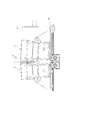
切断機構20は、第1クランプ装置21、第2クランプ装置23、刃25、給送ユニット27、プッシュプル装置28、及びプッシュ装置29を含み、第1クランプ装置21と第2クランプ装置23は、隣接して、両装置間で間隙223を形成する。
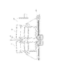
その結果、切断するロール繊維製品221間の切れ目を増大するために、第1プッシュユニット291は、第1接続ユニット213を、第1シャフト217周りに揺動させるように駆動でき、第2プッシュユニット293は、第2接続ユニット233を第2シャフト237周りに揺動させるように駆動できる。
切断機構20のクランプ装置30は、少なくとも1つのクランプ部311及び少なくとも1つの支持部313を含む。例えば、クランプ装置30は、2つのクランプ部311及び2つの支持部313を含んでもよい。ロール繊維製品221は、支持部313上に置かれ、クランプ部311は、ロール繊維製品221及び支持部313の上方に位置する。クランプ部311と支持部313は、それらの間にロール繊維製品221を、刃25がロール繊維製品221を切断するのを支援するために、挟持する。更に、図2の第1クランプユニット215及び図3の第2クランプユニット235は、クランプ部311及び支持部313を含んでもよい。
図2を参照されたい。給送ユニット27は、ロール繊維製品221を、第1クランプ装置21及び第2クランプ装置23に給送している。ロール繊維製品221が、給送ユニット27によって所定位置へ押されると、第1クランプ装置21及び第2クランプ装置23が作動されて、図4で示されるように、ロール繊維製品221を挟持して、ロール繊維製品221の位置を固定する。
ロール繊維製品221が第1クランプ装置21及び第2クランプ装置23の所定位置まで給送ユニット27によって押されると、第1クランプ装置21及び第2クランプ装置23は、図2で示されるように、切断のために、ロール繊維製品221を挟持する。
Claims (10)
- 第1座部、該第1座部に第1シャフトを介して接続される第1接続ユニット、ロール繊維製品を挟持するための、前記第1接続ユニットに接続される第1クランプユニット、を含む第1クランプ装置、
該第1クランプ装置に隣接し、間隙が前記第1クランプ装置と前記第2クランプ装置との間に形成される第2クランプ装置であって、第2座部、該第2座部に第2シャフトを介して接続される第2接続ユニット、前記ロール繊維製品を挟持するための、前記第2接続ユニットに接続される第2クランプユニット、を含む第2クランプ装置、
前記間隙に配置された前記ロール繊維製品を切断するための刃、
前記ロール繊維製品を、前記第2クランプ装置から前記第1クランプ装置に給送する給送ユニット、
前記第1座部及び前記第2座部に其々接続された第1プッシュプルユニット及び第2プッシュプルユニットを含むプッシュプル装置であって、前記第1プッシュプルユニット及び前記第2プッシュプルユニットは、前記第1クランプ装置及び前記第2クランプ装置の変位を其々駆動して、前記第1クランプ装置と前記第2クランプ装置との間の前記間隙の大きさを調節する、プッシュプル装置、及び、
前記第1接続ユニット及び前記第2接続ユニットに其々接続され、前記第1接続ユニット及び前記第2接続ユニットを、前記第1座部及び前記第2座部に対して前記第1シャフト及び前記第2シャフト周りに揺動するように駆動する第1プッシュユニット及び第2プッシュユニットを含む、プッシュ装置、を含む、
ロール繊維製品用切断機構。 - 前記第1クランプユニットと前記第2クランプユニットの両方は、前記ロール繊維製品を支持するための少なくとも1つの支持部、及び前記ロール繊維製品を挟持するための少なくとも1つのクランプ部を含むことを特徴とする、請求項1の切断機構。
- 前記第1クランプ装置及び前記第2クランプ装置は、複数のホイール、サーボモータ、及び、前記第1クランプユニット及び前記第2クランプユニットの前記クランプ部に接続され、前記ホイール及び前記サーボモータ上に設置される連結帯であって、前記サーボモータの回転により、前記クランプ部を、前記連結帯を介して駆動して、前記ロール繊維製品を挟持することを特徴とする、請求項2の切断機構。
- 前記サーボモータ又は前記連結帯に、揺動アームを介して接続されて、前記クランプ部の位置を前記連結帯を介して固定し、又は前記クランプ部の変位を前記連結帯を介し駆動する、シリンダを含むことを特徴とする、請求項3の切断機構。
- 前記第1クランプ装置と前記第2クランプ装置の両方は、複数の摺動レール及び複数の摺動ブロックを含み、各前記摺動ブロックは、前記クランプ部に接続され、対応する前記摺動レール上に配置され、前記サーボモータの回転により、前記クランプ部及び前記摺動ブロックを、前記摺動レールに沿って、前記連結帯を介して移動させて、前記ロール繊維製品を挟持するように駆動することを特徴とする、請求項4の切断機構。
- 前記第1プッシュプルユニットと前記第2プッシュプルユニットの両方は、少なくとも1個のカム及び少なくとも1本の連結ロッドを含み、前記第1プッシュプルユニット及び前記プッシュプルユニットの前記カムは、対応する前記第1座部及び前記第2座部に、前記連結ロッドを介して接続されることを特徴とする、請求項1の切断機構。
- 前記第1プッシュプルユニット及び前記第2プッシュプルユニットの前記カムは、ロッド上に配置され、前記ロッドの回転により、前記第1クランプ装置及び前記第2クランプ装置の前記カムを、回転又は揺動するように駆動させて、前記第1クランプ装置と前記第2クランプ装置との前記間隙の前記大きさを調節することを特徴とする、請求項6の切断機構。
- 前記第1クランプ装置の前記第1座部及び前記第2クランプ装置の前記第2座部は、摺動レール上に配置された少なくとも1個の摺動ブロックに其々接続され、前記第1プッシュプルユニットと前記第2プッシュプルユニットは、対応する前記第1座部及び前記第2座部に、前記摺動ブロックを介して接続されて、前記第1座部及び前記第2座部を、前記摺動レールに沿って移動するように駆動することを特徴とする、請求項1の切断機構。
- 前記第1プッシュユニットと前記第2プッシュユニットの両方は、少なくとも1個のカムを含み、前記第1プッシュユニット及び前記第2プッシュユニットの前記カムは、対応する前記第1接続ユニット及び前記第2接続ユニットを、前記第2座部及び前記第2座部に対して揺動するように駆動することを特徴とする、請求項1の切断機構。
- 前記第1プッシュユニット及び前記第2プッシュユニットの前記カムは、其々、前記第1座部及び前記第2座部に、減速機(reducer)を介して接続されるロッドに、接続されることを特徴とする、請求項9の切断機構。
Applications Claiming Priority (2)
| Application Number | Priority Date | Filing Date | Title |
|---|---|---|---|
| TW107115363A TWI676540B (zh) | 2018-05-07 | 2018-05-07 | 捲筒式纖維製品的裁切機構 |
| TW107115363 | 2018-05-07 |
Publications (2)
| Publication Number | Publication Date |
|---|---|
| JP2019195902A true JP2019195902A (ja) | 2019-11-14 |
| JP6744948B2 JP6744948B2 (ja) | 2020-08-19 |
Family
ID=66448438
Family Applications (1)
| Application Number | Title | Priority Date | Filing Date |
|---|---|---|---|
| JP2019081860A Active JP6744948B2 (ja) | 2018-05-07 | 2019-04-23 | ロール繊維製品用切断機構 |
Country Status (4)
| Country | Link |
|---|---|
| US (1) | US10695934B2 (ja) |
| EP (1) | EP3566833B1 (ja) |
| JP (1) | JP6744948B2 (ja) |
| TW (1) | TWI676540B (ja) |
Families Citing this family (2)
| Publication number | Priority date | Publication date | Assignee | Title |
|---|---|---|---|---|
| CN113231870B (zh) * | 2021-07-12 | 2021-09-07 | 烟台海上航天科技有限公司 | 弧形卫星天线面板边缘切割装置 |
| CN114536465B (zh) * | 2022-03-02 | 2022-12-23 | 广州泰达纤维制品有限公司 | 一种吸湿速干纤维生产加工装置 |
Family Cites Families (7)
| Publication number | Priority date | Publication date | Assignee | Title |
|---|---|---|---|---|
| US3978747A (en) * | 1975-03-24 | 1976-09-07 | The Gates Rubber Company | Method and apparatus for severing reinforced elastomeric tubular articles |
| DE3238809A1 (de) * | 1982-10-20 | 1984-04-26 | Achenbach Buschhütten GmbH, 5910 Kreuztal | Werkstueckspannvorrichtung fuer metallsaegemaschinen |
| US6532851B2 (en) * | 2000-12-21 | 2003-03-18 | Paper Converting Machine Company | Apparatus for supporting product during cutting |
| ES2451569T3 (es) * | 2004-03-31 | 2014-03-27 | M T C - Macchine Trasformazione Carta S.R.L. | Método de corte transversal de cintas continuas de papel y elementos similares |
| US7866238B2 (en) * | 2006-06-22 | 2011-01-11 | Chan Li Machinery Co., Ltd. | Sawing apparatus for cutting rolls of web material |
| ITMI20110221A1 (it) * | 2011-02-15 | 2012-08-16 | Gambini Int Sa | Apparecchiatura per taglio di log di carta in una pluralitá di rotoli |
| TWI487609B (zh) * | 2012-03-06 | 2015-06-11 | Chan Li Machinery Co Ltd | Crop screening device for fiber products and cutting and screening method |
-
2018
- 2018-05-07 TW TW107115363A patent/TWI676540B/zh active
-
2019
- 2019-04-23 JP JP2019081860A patent/JP6744948B2/ja active Active
- 2019-04-29 US US16/397,153 patent/US10695934B2/en active Active
- 2019-05-07 EP EP19173188.4A patent/EP3566833B1/en active Active
Also Published As
| Publication number | Publication date |
|---|---|
| EP3566833A1 (en) | 2019-11-13 |
| TWI676540B (zh) | 2019-11-11 |
| EP3566833B1 (en) | 2021-11-03 |
| TW201946748A (zh) | 2019-12-16 |
| US20190337179A1 (en) | 2019-11-07 |
| JP6744948B2 (ja) | 2020-08-19 |
| US10695934B2 (en) | 2020-06-30 |
Similar Documents
| Publication | Publication Date | Title |
|---|---|---|
| JP5633676B2 (ja) | 補強コード入りゴムシート材の切断方法及びその装置 | |
| CN206654498U (zh) | 一种电池片传送校正装置 | |
| JP5221412B2 (ja) | カーカスプライの接合装置 | |
| US6508153B1 (en) | Conveyor product transfer apparatus and method | |
| JP2019195902A (ja) | ロール繊維製品用切断機構 | |
| CN104970496B (zh) | 一种机械手音波拉链切断机及切断方法 | |
| JP2011229479A (ja) | 食品生地の整列方法及び装置 | |
| US20160235593A1 (en) | Device for producing disposable wearable article and method for producing disposable wearable article | |
| JP5604187B2 (ja) | シート貼付装置および貼付方法 | |
| CN112188949B (zh) | 内置帘线的橡胶片构件的切断装置及方法 | |
| KR101059073B1 (ko) | 가변형 롤포밍장치 | |
| JP5137090B2 (ja) | 間欠塗工方法及び間欠塗工装置 | |
| CN106040806A (zh) | 自动弯管装置 | |
| JP4753649B2 (ja) | タイヤ構成部材の製造方法および製造装置。 | |
| JP6499491B2 (ja) | タイヤ用プライ製造装置 | |
| RU2648925C1 (ru) | Соединительное устройство для соединения компонентов шины | |
| JP5615079B2 (ja) | レール頭頂面の削正装置 | |
| JP2016216085A (ja) | トップシール装置、包装機及び包装体製造方法 | |
| CN110453487A (zh) | 卷筒式纤维制品的裁切机构 | |
| KR101612886B1 (ko) | 외주링 결속장치 | |
| CN218015461U (zh) | 一种机电工程电缆裁切装置 | |
| JP2018153869A (ja) | シート切断装置及びシート製造方法 | |
| CN120439390A (zh) | 一种双工位生产线和生产方法 | |
| JP2004141959A (ja) | 刃材曲げ加工方法及び刃材曲げ加工装置 | |
| KR101529181B1 (ko) | 턴테이블 장치 |
Legal Events
| Date | Code | Title | Description |
|---|---|---|---|
| A621 | Written request for application examination |
Free format text: JAPANESE INTERMEDIATE CODE: A621 Effective date: 20190528 |
|
| A131 | Notification of reasons for refusal |
Free format text: JAPANESE INTERMEDIATE CODE: A131 Effective date: 20200310 |
|
| A521 | Request for written amendment filed |
Free format text: JAPANESE INTERMEDIATE CODE: A523 Effective date: 20200610 |
|
| TRDD | Decision of grant or rejection written | ||
| A01 | Written decision to grant a patent or to grant a registration (utility model) |
Free format text: JAPANESE INTERMEDIATE CODE: A01 Effective date: 20200707 |
|
| A61 | First payment of annual fees (during grant procedure) |
Free format text: JAPANESE INTERMEDIATE CODE: A61 Effective date: 20200731 |
|
| R150 | Certificate of patent or registration of utility model |
Ref document number: 6744948 Country of ref document: JP Free format text: JAPANESE INTERMEDIATE CODE: R150 |
|
| R250 | Receipt of annual fees |
Free format text: JAPANESE INTERMEDIATE CODE: R250 |
|
| R250 | Receipt of annual fees |
Free format text: JAPANESE INTERMEDIATE CODE: R250 |
|
| R250 | Receipt of annual fees |
Free format text: JAPANESE INTERMEDIATE CODE: R250 |