JP2019200928A - 車両用灯具 - Google Patents
車両用灯具 Download PDFInfo
- Publication number
- JP2019200928A JP2019200928A JP2018095193A JP2018095193A JP2019200928A JP 2019200928 A JP2019200928 A JP 2019200928A JP 2018095193 A JP2018095193 A JP 2018095193A JP 2018095193 A JP2018095193 A JP 2018095193A JP 2019200928 A JP2019200928 A JP 2019200928A
- Authority
- JP
- Japan
- Prior art keywords
- light
- incident
- light source
- light guide
- unit
- Prior art date
- Legal status (The legal status is an assumption and is not a legal conclusion. Google has not performed a legal analysis and makes no representation as to the accuracy of the status listed.)
- Granted
Links
Images


Classifications
-
- B—PERFORMING OPERATIONS; TRANSPORTING
- B60—VEHICLES IN GENERAL
- B60Q—ARRANGEMENT OF SIGNALLING OR LIGHTING DEVICES, THE MOUNTING OR SUPPORTING THEREOF OR CIRCUITS THEREFOR, FOR VEHICLES IN GENERAL
- B60Q1/00—Arrangement of optical signalling or lighting devices, the mounting or supporting thereof or circuits therefor
- B60Q1/0011—Arrangement of optical signalling or lighting devices, the mounting or supporting thereof or circuits therefor with light guides for distributing the light between several lighting or signalling devices
-
- F—MECHANICAL ENGINEERING; LIGHTING; HEATING; WEAPONS; BLASTING
- F21—LIGHTING
- F21S—NON-PORTABLE LIGHTING DEVICES; SYSTEMS THEREOF; VEHICLE LIGHTING DEVICES SPECIALLY ADAPTED FOR VEHICLE EXTERIORS
- F21S43/00—Signalling devices specially adapted for vehicle exteriors, e.g. brake lamps, direction indicator lights or reversing lights
- F21S43/20—Signalling devices specially adapted for vehicle exteriors, e.g. brake lamps, direction indicator lights or reversing lights characterised by refractors, transparent cover plates, light guides or filters
- F21S43/235—Light guides
- F21S43/236—Light guides characterised by the shape of the light guide
- F21S43/239—Light guides characterised by the shape of the light guide plate-shaped
-
- F—MECHANICAL ENGINEERING; LIGHTING; HEATING; WEAPONS; BLASTING
- F21—LIGHTING
- F21S—NON-PORTABLE LIGHTING DEVICES; SYSTEMS THEREOF; VEHICLE LIGHTING DEVICES SPECIALLY ADAPTED FOR VEHICLE EXTERIORS
- F21S41/00—Illuminating devices specially adapted for vehicle exteriors, e.g. headlamps
- F21S41/20—Illuminating devices specially adapted for vehicle exteriors, e.g. headlamps characterised by refractors, transparent cover plates, light guides or filters
- F21S41/24—Light guides
-
- F—MECHANICAL ENGINEERING; LIGHTING; HEATING; WEAPONS; BLASTING
- F21—LIGHTING
- F21S—NON-PORTABLE LIGHTING DEVICES; SYSTEMS THEREOF; VEHICLE LIGHTING DEVICES SPECIALLY ADAPTED FOR VEHICLE EXTERIORS
- F21S43/00—Signalling devices specially adapted for vehicle exteriors, e.g. brake lamps, direction indicator lights or reversing lights
- F21S43/20—Signalling devices specially adapted for vehicle exteriors, e.g. brake lamps, direction indicator lights or reversing lights characterised by refractors, transparent cover plates, light guides or filters
- F21S43/235—Light guides
- F21S43/236—Light guides characterised by the shape of the light guide
-
- F—MECHANICAL ENGINEERING; LIGHTING; HEATING; WEAPONS; BLASTING
- F21—LIGHTING
- F21S—NON-PORTABLE LIGHTING DEVICES; SYSTEMS THEREOF; VEHICLE LIGHTING DEVICES SPECIALLY ADAPTED FOR VEHICLE EXTERIORS
- F21S43/00—Signalling devices specially adapted for vehicle exteriors, e.g. brake lamps, direction indicator lights or reversing lights
- F21S43/20—Signalling devices specially adapted for vehicle exteriors, e.g. brake lamps, direction indicator lights or reversing lights characterised by refractors, transparent cover plates, light guides or filters
- F21S43/235—Light guides
- F21S43/242—Light guides characterised by the emission area
- F21S43/245—Light guides characterised by the emission area emitting light from one or more of its major surfaces
-
- F—MECHANICAL ENGINEERING; LIGHTING; HEATING; WEAPONS; BLASTING
- F21—LIGHTING
- F21S—NON-PORTABLE LIGHTING DEVICES; SYSTEMS THEREOF; VEHICLE LIGHTING DEVICES SPECIALLY ADAPTED FOR VEHICLE EXTERIORS
- F21S43/00—Signalling devices specially adapted for vehicle exteriors, e.g. brake lamps, direction indicator lights or reversing lights
- F21S43/20—Signalling devices specially adapted for vehicle exteriors, e.g. brake lamps, direction indicator lights or reversing lights characterised by refractors, transparent cover plates, light guides or filters
- F21S43/235—Light guides
- F21S43/249—Light guides with two or more light sources being coupled into the light guide
-
- G—PHYSICS
- G02—OPTICS
- G02B—OPTICAL ELEMENTS, SYSTEMS OR APPARATUS
- G02B6/00—Light guides; Structural details of arrangements comprising light guides and other optical elements, e.g. couplings
- G02B6/0001—Light guides; Structural details of arrangements comprising light guides and other optical elements, e.g. couplings specially adapted for lighting devices or systems
- G02B6/0011—Light guides; Structural details of arrangements comprising light guides and other optical elements, e.g. couplings specially adapted for lighting devices or systems the light guides being planar or of plate-like form
- G02B6/0013—Means for improving the coupling-in of light from the light source into the light guide
- G02B6/0015—Means for improving the coupling-in of light from the light source into the light guide provided on the surface of the light guide or in the bulk of it
- G02B6/0018—Redirecting means on the surface of the light guide
-
- G—PHYSICS
- G02—OPTICS
- G02B—OPTICAL ELEMENTS, SYSTEMS OR APPARATUS
- G02B6/00—Light guides; Structural details of arrangements comprising light guides and other optical elements, e.g. couplings
- G02B6/0001—Light guides; Structural details of arrangements comprising light guides and other optical elements, e.g. couplings specially adapted for lighting devices or systems
- G02B6/0011—Light guides; Structural details of arrangements comprising light guides and other optical elements, e.g. couplings specially adapted for lighting devices or systems the light guides being planar or of plate-like form
- G02B6/0013—Means for improving the coupling-in of light from the light source into the light guide
- G02B6/0015—Means for improving the coupling-in of light from the light source into the light guide provided on the surface of the light guide or in the bulk of it
- G02B6/002—Means for improving the coupling-in of light from the light source into the light guide provided on the surface of the light guide or in the bulk of it by shaping at least a portion of the light guide, e.g. with collimating, focussing or diverging surfaces
- G02B6/0021—Means for improving the coupling-in of light from the light source into the light guide provided on the surface of the light guide or in the bulk of it by shaping at least a portion of the light guide, e.g. with collimating, focussing or diverging surfaces for housing at least a part of the light source, e.g. by forming holes or recesses
-
- G—PHYSICS
- G02—OPTICS
- G02B—OPTICAL ELEMENTS, SYSTEMS OR APPARATUS
- G02B6/00—Light guides; Structural details of arrangements comprising light guides and other optical elements, e.g. couplings
- G02B6/0001—Light guides; Structural details of arrangements comprising light guides and other optical elements, e.g. couplings specially adapted for lighting devices or systems
- G02B6/0011—Light guides; Structural details of arrangements comprising light guides and other optical elements, e.g. couplings specially adapted for lighting devices or systems the light guides being planar or of plate-like form
- G02B6/0013—Means for improving the coupling-in of light from the light source into the light guide
- G02B6/0023—Means for improving the coupling-in of light from the light source into the light guide provided by one optical element, or plurality thereof, placed between the light guide and the light source, or around the light source
- G02B6/0028—Light guide, e.g. taper
-
- G—PHYSICS
- G02—OPTICS
- G02B—OPTICAL ELEMENTS, SYSTEMS OR APPARATUS
- G02B6/00—Light guides; Structural details of arrangements comprising light guides and other optical elements, e.g. couplings
- G02B6/0001—Light guides; Structural details of arrangements comprising light guides and other optical elements, e.g. couplings specially adapted for lighting devices or systems
- G02B6/0011—Light guides; Structural details of arrangements comprising light guides and other optical elements, e.g. couplings specially adapted for lighting devices or systems the light guides being planar or of plate-like form
- G02B6/0013—Means for improving the coupling-in of light from the light source into the light guide
- G02B6/0023—Means for improving the coupling-in of light from the light source into the light guide provided by one optical element, or plurality thereof, placed between the light guide and the light source, or around the light source
- G02B6/0031—Reflecting element, sheet or layer
-
- G—PHYSICS
- G02—OPTICS
- G02B—OPTICAL ELEMENTS, SYSTEMS OR APPARATUS
- G02B6/00—Light guides; Structural details of arrangements comprising light guides and other optical elements, e.g. couplings
- G02B6/0001—Light guides; Structural details of arrangements comprising light guides and other optical elements, e.g. couplings specially adapted for lighting devices or systems
- G02B6/0011—Light guides; Structural details of arrangements comprising light guides and other optical elements, e.g. couplings specially adapted for lighting devices or systems the light guides being planar or of plate-like form
- G02B6/0033—Means for improving the coupling-out of light from the light guide
- G02B6/0035—Means for improving the coupling-out of light from the light guide provided on the surface of the light guide or in the bulk of it
- G02B6/0045—Means for improving the coupling-out of light from the light guide provided on the surface of the light guide or in the bulk of it by shaping at least a portion of the light guide
- G02B6/0046—Tapered light guide, e.g. wedge-shaped light guide
-
- G—PHYSICS
- G02—OPTICS
- G02B—OPTICAL ELEMENTS, SYSTEMS OR APPARATUS
- G02B6/00—Light guides; Structural details of arrangements comprising light guides and other optical elements, e.g. couplings
- G02B6/0001—Light guides; Structural details of arrangements comprising light guides and other optical elements, e.g. couplings specially adapted for lighting devices or systems
- G02B6/0011—Light guides; Structural details of arrangements comprising light guides and other optical elements, e.g. couplings specially adapted for lighting devices or systems the light guides being planar or of plate-like form
- G02B6/0066—Light guides; Structural details of arrangements comprising light guides and other optical elements, e.g. couplings specially adapted for lighting devices or systems the light guides being planar or of plate-like form characterised by the light source being coupled to the light guide
- G02B6/0073—Light emitting diode [LED]
-
- F—MECHANICAL ENGINEERING; LIGHTING; HEATING; WEAPONS; BLASTING
- F21—LIGHTING
- F21S—NON-PORTABLE LIGHTING DEVICES; SYSTEMS THEREOF; VEHICLE LIGHTING DEVICES SPECIALLY ADAPTED FOR VEHICLE EXTERIORS
- F21S43/00—Signalling devices specially adapted for vehicle exteriors, e.g. brake lamps, direction indicator lights or reversing lights
- F21S43/10—Signalling devices specially adapted for vehicle exteriors, e.g. brake lamps, direction indicator lights or reversing lights characterised by the light source
- F21S43/13—Signalling devices specially adapted for vehicle exteriors, e.g. brake lamps, direction indicator lights or reversing lights characterised by the light source characterised by the type of light source
- F21S43/14—Light emitting diodes [LED]
-
- F—MECHANICAL ENGINEERING; LIGHTING; HEATING; WEAPONS; BLASTING
- F21—LIGHTING
- F21S—NON-PORTABLE LIGHTING DEVICES; SYSTEMS THEREOF; VEHICLE LIGHTING DEVICES SPECIALLY ADAPTED FOR VEHICLE EXTERIORS
- F21S43/00—Signalling devices specially adapted for vehicle exteriors, e.g. brake lamps, direction indicator lights or reversing lights
- F21S43/30—Signalling devices specially adapted for vehicle exteriors, e.g. brake lamps, direction indicator lights or reversing lights characterised by reflectors
- F21S43/31—Optical layout thereof
- F21S43/315—Optical layout thereof using total internal reflection
-
- F—MECHANICAL ENGINEERING; LIGHTING; HEATING; WEAPONS; BLASTING
- F21—LIGHTING
- F21V—FUNCTIONAL FEATURES OR DETAILS OF LIGHTING DEVICES OR SYSTEMS THEREOF; STRUCTURAL COMBINATIONS OF LIGHTING DEVICES WITH OTHER ARTICLES, NOT OTHERWISE PROVIDED FOR
- F21V2200/00—Use of light guides, e.g. fibre optic devices, in lighting devices or systems
- F21V2200/20—Use of light guides, e.g. fibre optic devices, in lighting devices or systems of light guides of a generally planar shape
-
- F—MECHANICAL ENGINEERING; LIGHTING; HEATING; WEAPONS; BLASTING
- F21—LIGHTING
- F21Y—INDEXING SCHEME ASSOCIATED WITH SUBCLASSES F21K, F21L, F21S and F21V, RELATING TO THE FORM OR THE KIND OF THE LIGHT SOURCES OR OF THE COLOUR OF THE LIGHT EMITTED
- F21Y2103/00—Elongate light sources, e.g. fluorescent tubes
- F21Y2103/10—Elongate light sources, e.g. fluorescent tubes comprising a linear array of point-like light-generating elements
-
- F—MECHANICAL ENGINEERING; LIGHTING; HEATING; WEAPONS; BLASTING
- F21—LIGHTING
- F21Y—INDEXING SCHEME ASSOCIATED WITH SUBCLASSES F21K, F21L, F21S and F21V, RELATING TO THE FORM OR THE KIND OF THE LIGHT SOURCES OR OF THE COLOUR OF THE LIGHT EMITTED
- F21Y2113/00—Combination of light sources
- F21Y2113/10—Combination of light sources of different colours
- F21Y2113/13—Combination of light sources of different colours comprising an assembly of point-like light sources
-
- F—MECHANICAL ENGINEERING; LIGHTING; HEATING; WEAPONS; BLASTING
- F21—LIGHTING
- F21Y—INDEXING SCHEME ASSOCIATED WITH SUBCLASSES F21K, F21L, F21S and F21V, RELATING TO THE FORM OR THE KIND OF THE LIGHT SOURCES OR OF THE COLOUR OF THE LIGHT EMITTED
- F21Y2115/00—Light-generating elements of semiconductor light sources
- F21Y2115/10—Light-emitting diodes [LED]
-
- G—PHYSICS
- G02—OPTICS
- G02B—OPTICAL ELEMENTS, SYSTEMS OR APPARATUS
- G02B6/00—Light guides; Structural details of arrangements comprising light guides and other optical elements, e.g. couplings
- G02B6/0001—Light guides; Structural details of arrangements comprising light guides and other optical elements, e.g. couplings specially adapted for lighting devices or systems
- G02B6/0011—Light guides; Structural details of arrangements comprising light guides and other optical elements, e.g. couplings specially adapted for lighting devices or systems the light guides being planar or of plate-like form
- G02B6/0013—Means for improving the coupling-in of light from the light source into the light guide
- G02B6/0015—Means for improving the coupling-in of light from the light source into the light guide provided on the surface of the light guide or in the bulk of it
- G02B6/002—Means for improving the coupling-in of light from the light source into the light guide provided on the surface of the light guide or in the bulk of it by shaping at least a portion of the light guide, e.g. with collimating, focussing or diverging surfaces
-
- G—PHYSICS
- G02—OPTICS
- G02B—OPTICAL ELEMENTS, SYSTEMS OR APPARATUS
- G02B6/00—Light guides; Structural details of arrangements comprising light guides and other optical elements, e.g. couplings
- G02B6/0001—Light guides; Structural details of arrangements comprising light guides and other optical elements, e.g. couplings specially adapted for lighting devices or systems
- G02B6/0011—Light guides; Structural details of arrangements comprising light guides and other optical elements, e.g. couplings specially adapted for lighting devices or systems the light guides being planar or of plate-like form
- G02B6/0033—Means for improving the coupling-out of light from the light guide
- G02B6/0035—Means for improving the coupling-out of light from the light guide provided on the surface of the light guide or in the bulk of it
- G02B6/0036—2-D arrangement of prisms, protrusions, indentations or roughened surfaces
Landscapes
- Physics & Mathematics (AREA)
- Engineering & Computer Science (AREA)
- General Physics & Mathematics (AREA)
- Optics & Photonics (AREA)
- General Engineering & Computer Science (AREA)
- Mechanical Engineering (AREA)
- Microelectronics & Electronic Packaging (AREA)
- Planar Illumination Modules (AREA)
- Non-Portable Lighting Devices Or Systems Thereof (AREA)
Abstract
Description
〔1〕 互いに隣り合う第1の光源及び第2の光源と、
前記第1の光源及び前記第2の光源からの光を互いに同一方向に向けて導光させる導光体とを備え、
前記導光体は、前記第1の光源及び前記第2の光源に各々対向して配置されて、前記第1の光源及び前記第2の光源からから出射された光が入射する第1の入射部及び第2の入射部と、
前記第1の入射部及び前記第2の入射部に対向して配置されて、前記第1の入射部及び前記第2の入射部から入射した光を互いに同一方向に向けて反射する反射部と、
前記反射部で反射された光を導光させる導光部とを有し、
前記第1の入射部は、前記第1の光源と対向する部分の中央に位置して、前記第1の光源から出射された光の一部が入射する第1の集光入射面と、前記第1の集光入射面の周囲を囲む位置から前記第1の光源側に突出した突出部とを有し、
前記第2の入射部は、前記第2の光源と対向する部分に位置して、前記第2の光源から出射された光が入射する第2の集光入射面を有し、
前記第3の集光入射面は、前記突出部に隣接して設けられていることを特徴とする車両用灯具。
〔2〕 前記第1の入射部及び前記第2の入射部は、前記第1の光源及び前記第2の光源から放射状に出射された光を平行化又は集光しながら、前記導光体の内部へと入射することを特徴とする前記〔1〕に記載の車両用灯具。
〔3〕 前記反射部は、前記導光部側に向けて傾斜した傾斜面を有し、
前記傾斜面は、前記第1の光源及び前記第2の光源が並ぶ方向に連続して設けられていることを特徴とする前記〔1〕又は〔2〕に記載の車両用灯具。
〔4〕 前記導光体は、前記反射部で反射された光を前記導光部の内部で導光しながら、前記導光部の背面側に設けられた複数の反射カットにより反射された光を前記導光部の正面側から外部へと出射することによって、前記導光部の正面側に設けられた発光部を発光させることを特徴とする前記〔1〕〜〔3〕の何れか一項に記載の車両用灯具。
〔5〕 前記第1の光源及び前記第2の光源は、前記反射部から前記導光部に向けて反射される光の進行方向とは交差する方向に交互に複数並んで設けられていることを特徴とする前記〔1〕〜〔4〕の何れか一項に記載の車両用灯具。
〔6〕 前記第1の光源と前記第2の光源とは、互いに異なる色光を出射することを特徴とする前記〔1〕〜〔5〕の何れか一項に記載の車両用灯具。
なお、以下の説明で用いる図面においては、各構成要素を見やすくするため、構成要素によって寸法の縮尺を異ならせて示すことがあり、各構成要素の寸法比率などが実際と同じであるとは限らない。
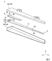
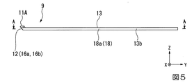
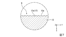
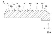
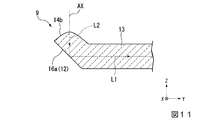
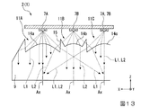
なお、図1は、車両用灯具1の構成を示す斜視図である。図2は、車両用灯具1の構成を示す分解斜視図である。図3は、車両用灯具1が備える灯具ユニット2の構成を示す分解斜視図である。図4は、灯具ユニット2が備える導光体9の構成を示す上面図である。図5は、灯具ユニット2が備える導光体9の構成を示す正面図である。図6は、図5中に示す線分A−Aによる導光体9の断面図である。図7は、図6中に示す囲み部分Bを拡大した導光体9の断面図である。図8は、図4に示す導光体9の要部を拡大して示す上面図である。図9は、図8中に示す線分C−Cによる導光体9の断面図である。図10は、図8中に示す線分D−Dによる導光体9の断面図である。図11は、図8中に示す線分E−Eによる導光体9の断面図である。図12は、図8中に示す線分F−Fによる導光体9の断面図である。図13は、図8に示す方向から見た第1の光源7A及び第2の光源7Bから出射された光L1,L2の光路を示す断面図である。
例えば、上記実施形態では、車両の前端側の両コーナー部に搭載される車両用灯具1として、白色発光する車幅灯(ポジションランプ)と、橙色発光で点滅する方向指示器(ターンランプ)とを組み合わせたポジションランプ兼ターンランプからなるものを例示しているが、車両の後端側の両コーナー部に搭載される車両用灯具として、赤色発光する尾灯(テールランプ)と、橙色発光で点滅する方向指示器(ターンランプ)とを組み合わせたテールランプ兼ターンランプからなるものに本発明を適用することも可能である。
Claims (6)
- 互いに隣り合う第1の光源及び第2の光源と、
前記第1の光源及び前記第2の光源からの光を互いに同一方向に向けて導光させる導光体とを備え、
前記導光体は、前記第1の光源及び前記第2の光源に各々対向して配置されて、前記第1の光源及び前記第2の光源からから出射された光が入射する第1の入射部及び第2の入射部と、
前記第1の入射部及び前記第2の入射部に対向して配置されて、前記第1の入射部及び前記第2の入射部から入射した光を互いに同一方向に向けて反射する反射部と、
前記反射部で反射された光を導光させる導光部とを有し、
前記第1の入射部は、前記第1の光源と対向する部分の中央に位置して、前記第1の光源から出射された光の一部が入射する第1の集光入射面と、前記第1の集光入射面の周囲を囲む位置から前記第1の光源側に突出した突出部とを有し、
前記第2の入射部は、前記第2の光源と対向する部分に位置して、前記第2の光源から出射された光が入射する第2の集光入射面を有し、
前記第3の集光入射面は、前記突出部に隣接して設けられていることを特徴とする車両用灯具。 - 前記第1の入射部及び前記第2の入射部は、前記第1の光源及び前記第2の光源から放射状に出射された光を平行化又は集光しながら、前記導光体の内部へと入射することを特徴とする請求項1に記載の車両用灯具。
- 前記反射部は、前記導光部側に向けて傾斜した傾斜面を有し、
前記傾斜面は、前記第1の光源及び前記第2の光源が並ぶ方向に連続して設けられていることを特徴とする請求項1又は2に記載の車両用灯具。 - 前記導光体は、前記反射部で反射された光を前記導光部の内部で導光しながら、前記導光部の背面側に設けられた複数の反射カットにより反射された光を前記導光部の正面側から外部へと出射することによって、前記導光部の正面側に設けられた発光部を発光させることを特徴とする請求項1〜3の何れか一項に記載の車両用灯具。
- 前記第1の光源及び前記第2の光源は、前記反射部から前記導光部に向けて反射される光の進行方向とは交差する方向に交互に複数並んで設けられていることを特徴とする請求項1〜4の何れか一項に記載の車両用灯具。
- 前記第1の光源と前記第2の光源とは、互いに異なる色光を出射することを特徴とする請求項1〜5の何れか一項に記載の車両用灯具。
Priority Applications (3)
| Application Number | Priority Date | Filing Date | Title |
|---|---|---|---|
| JP2018095193A JP7081977B2 (ja) | 2018-05-17 | 2018-05-17 | 車両用灯具 |
| US16/412,016 US10661699B2 (en) | 2018-05-17 | 2019-05-14 | Lighting tool for vehicle including light sources and light guide body |
| EP19174515.7A EP3572724A1 (en) | 2018-05-17 | 2019-05-14 | Lighting tool for vehicle |
Applications Claiming Priority (1)
| Application Number | Priority Date | Filing Date | Title |
|---|---|---|---|
| JP2018095193A JP7081977B2 (ja) | 2018-05-17 | 2018-05-17 | 車両用灯具 |
Publications (2)
| Publication Number | Publication Date |
|---|---|
| JP2019200928A true JP2019200928A (ja) | 2019-11-21 |
| JP7081977B2 JP7081977B2 (ja) | 2022-06-07 |
Family
ID=66554198
Family Applications (1)
| Application Number | Title | Priority Date | Filing Date |
|---|---|---|---|
| JP2018095193A Active JP7081977B2 (ja) | 2018-05-17 | 2018-05-17 | 車両用灯具 |
Country Status (3)
| Country | Link |
|---|---|
| US (1) | US10661699B2 (ja) |
| EP (1) | EP3572724A1 (ja) |
| JP (1) | JP7081977B2 (ja) |
Cited By (1)
| Publication number | Priority date | Publication date | Assignee | Title |
|---|---|---|---|---|
| WO2023199592A1 (ja) * | 2022-04-13 | 2023-10-19 | パナソニックIpマネジメント株式会社 | 面発光装置、表示装置、及び照明装置 |
Families Citing this family (7)
| Publication number | Priority date | Publication date | Assignee | Title |
|---|---|---|---|---|
| DE102017124296A1 (de) | 2017-10-18 | 2019-04-18 | Carl Zeiss Jena Gmbh | Leuchteinrichtung für Fahrzeuge |
| JP7079654B2 (ja) * | 2018-05-17 | 2022-06-02 | スタンレー電気株式会社 | 車両用灯具 |
| DE102018115574A1 (de) | 2018-06-28 | 2020-01-02 | Carl Zeiss Jena Gmbh | Leuchteneinrichtung für Fahrzeuge |
| DE102018117001A1 (de) | 2018-07-13 | 2020-01-16 | Carl Zeiss Jena Gmbh | Leuchteinrichtung für Fahrzeuge |
| ES2973155T3 (es) * | 2018-09-17 | 2024-06-18 | Lmpg Inc | Guías de luz en forma de cuña para luminarias y conjuntos de luminarias que las incorporan |
| EP3938328A1 (en) | 2019-03-14 | 2022-01-19 | Pilkington Group Limited | Glass article having an anti-reflective coating |
| JP2023155612A (ja) * | 2022-04-11 | 2023-10-23 | スタンレー電気株式会社 | 車両用灯具 |
Citations (2)
| Publication number | Priority date | Publication date | Assignee | Title |
|---|---|---|---|---|
| JP2012119277A (ja) * | 2010-12-03 | 2012-06-21 | Stanley Electric Co Ltd | 車両用光学ユニット |
| JP2017183287A (ja) * | 2016-03-29 | 2017-10-05 | スタンレー電気株式会社 | 車両用灯具 |
Family Cites Families (9)
| Publication number | Priority date | Publication date | Assignee | Title |
|---|---|---|---|---|
| US6186636B1 (en) * | 1999-06-11 | 2001-02-13 | Design Rite, Llc. | Apparatus for illuminating a portable electronic or computing device |
| CN1288006C (zh) * | 2001-03-27 | 2006-12-06 | 梅里迪安机动车系统公司 | 灯具总成以及发散来自光源的光线的方法 |
| JP5518559B2 (ja) * | 2010-04-22 | 2014-06-11 | スタンレー電気株式会社 | 灯具ユニット |
| JP5615054B2 (ja) | 2010-06-18 | 2014-10-29 | 株式会社小糸製作所 | 車輌用灯具 |
| JP6203519B2 (ja) | 2012-09-13 | 2017-09-27 | 株式会社小糸製作所 | 車両用灯具 |
| BR112016006653A2 (pt) * | 2013-09-27 | 2017-08-01 | Basf Se | uso de uma composição e sistemas de refrigeração, unidades de controle de clima, bombas de calor e geradores magnetocalóricos |
| JP2016006729A (ja) * | 2014-06-20 | 2016-01-14 | スタンレー電気株式会社 | 車両用灯具 |
| CZ2016481A3 (cs) | 2016-08-08 | 2018-02-21 | Varroc Lighting Systems, s.r.o. | Světelné zařízení pro motorová vozidla |
| CZ307412B6 (cs) * | 2017-06-13 | 2018-08-01 | Varroc Lighting Systems, s.r.o. | Světlovodivý optický systém |
-
2018
- 2018-05-17 JP JP2018095193A patent/JP7081977B2/ja active Active
-
2019
- 2019-05-14 EP EP19174515.7A patent/EP3572724A1/en not_active Withdrawn
- 2019-05-14 US US16/412,016 patent/US10661699B2/en active Active
Patent Citations (2)
| Publication number | Priority date | Publication date | Assignee | Title |
|---|---|---|---|---|
| JP2012119277A (ja) * | 2010-12-03 | 2012-06-21 | Stanley Electric Co Ltd | 車両用光学ユニット |
| JP2017183287A (ja) * | 2016-03-29 | 2017-10-05 | スタンレー電気株式会社 | 車両用灯具 |
Cited By (2)
| Publication number | Priority date | Publication date | Assignee | Title |
|---|---|---|---|---|
| WO2023199592A1 (ja) * | 2022-04-13 | 2023-10-19 | パナソニックIpマネジメント株式会社 | 面発光装置、表示装置、及び照明装置 |
| US12416756B2 (en) | 2022-04-13 | 2025-09-16 | Panasonic Intellectual Property Management Co., Ltd. | Surface light-emitting device, display device, and illumination device |
Also Published As
| Publication number | Publication date |
|---|---|
| EP3572724A1 (en) | 2019-11-27 |
| US10661699B2 (en) | 2020-05-26 |
| JP7081977B2 (ja) | 2022-06-07 |
| US20190351814A1 (en) | 2019-11-21 |
Similar Documents
| Publication | Publication Date | Title |
|---|---|---|
| JP2019200928A (ja) | 車両用灯具 | |
| JP4930787B2 (ja) | 車両用灯具、及び、車両用灯具に用いられる導光レンズ | |
| JP7211903B2 (ja) | 車両用灯具 | |
| JP6082992B2 (ja) | 照明装置、灯具および車両 | |
| JP2019023965A (ja) | 車両用灯具 | |
| JP7483523B2 (ja) | 車両用灯具 | |
| JP7418492B2 (ja) | 車両用灯具 | |
| US10598335B2 (en) | Lighting tool for vehicle | |
| JP7265437B2 (ja) | 車両用灯具 | |
| JP6725282B2 (ja) | 車両用灯具 | |
| JP7483473B2 (ja) | 車両用灯具 | |
| EP3581846B1 (en) | Vehicular lamp | |
| JP7579709B2 (ja) | 車両用灯具 | |
| JP7440315B2 (ja) | 車両用灯具 | |
| JP2019200937A (ja) | 車両用灯具 | |
| JP2019169241A (ja) | 車両用灯具 | |
| JP2018120658A (ja) | 車両用灯具 | |
| JP2020038777A (ja) | 車両用灯具 | |
| JP2020038769A (ja) | 車両用灯具 | |
| JP7401289B2 (ja) | 車両用灯具 | |
| JP7023780B2 (ja) | 車両用灯具 | |
| JP7390244B2 (ja) | 車両用灯具 | |
| JP2020038800A (ja) | 車両用灯具 | |
| JP7347968B2 (ja) | 車両用灯具 | |
| JP2024035419A (ja) | 車両用灯具 |
Legal Events
| Date | Code | Title | Description |
|---|---|---|---|
| A621 | Written request for application examination |
Free format text: JAPANESE INTERMEDIATE CODE: A621 Effective date: 20210414 |
|
| A977 | Report on retrieval |
Free format text: JAPANESE INTERMEDIATE CODE: A971007 Effective date: 20220216 |
|
| A131 | Notification of reasons for refusal |
Free format text: JAPANESE INTERMEDIATE CODE: A131 Effective date: 20220301 |
|
| A521 | Request for written amendment filed |
Free format text: JAPANESE INTERMEDIATE CODE: A523 Effective date: 20220414 |
|
| TRDD | Decision of grant or rejection written | ||
| A01 | Written decision to grant a patent or to grant a registration (utility model) |
Free format text: JAPANESE INTERMEDIATE CODE: A01 Effective date: 20220510 |
|
| A61 | First payment of annual fees (during grant procedure) |
Free format text: JAPANESE INTERMEDIATE CODE: A61 Effective date: 20220526 |
|
| R150 | Certificate of patent or registration of utility model |
Ref document number: 7081977 Country of ref document: JP Free format text: JAPANESE INTERMEDIATE CODE: R150 |
|
| R250 | Receipt of annual fees |
Free format text: JAPANESE INTERMEDIATE CODE: R250 |
|
| R250 | Receipt of annual fees |
Free format text: JAPANESE INTERMEDIATE CODE: R250 |