JP2019201039A - Electromagnetic coil unit - Google Patents
Electromagnetic coil unit Download PDFInfo
- Publication number
- JP2019201039A JP2019201039A JP2018093118A JP2018093118A JP2019201039A JP 2019201039 A JP2019201039 A JP 2019201039A JP 2018093118 A JP2018093118 A JP 2018093118A JP 2018093118 A JP2018093118 A JP 2018093118A JP 2019201039 A JP2019201039 A JP 2019201039A
- Authority
- JP
- Japan
- Prior art keywords
- electromagnetic coil
- terminal portion
- internal terminal
- bobbin
- coil unit
- Prior art date
- Legal status (The legal status is an assumption and is not a legal conclusion. Google has not performed a legal analysis and makes no representation as to the accuracy of the status listed.)
- Granted
Links
Images



Classifications
-
- H—ELECTRICITY
- H01—ELECTRIC ELEMENTS
- H01F—MAGNETS; INDUCTANCES; TRANSFORMERS; SELECTION OF MATERIALS FOR THEIR MAGNETIC PROPERTIES
- H01F27/00—Details of transformers or inductances, in general
- H01F27/28—Coils; Windings; Conductive connections
- H01F27/29—Terminals; Tapping arrangements for signal inductances
Landscapes
- Engineering & Computer Science (AREA)
- Power Engineering (AREA)
- Magnetically Actuated Valves (AREA)
- Coils Of Transformers For General Uses (AREA)
- Electromagnets (AREA)
Abstract
【課題】電磁コイル部1をモールド樹脂部3で封止する電磁コイルユニットにおいて、電磁コイル部1と接続する端子部材2の組み付けが容易で端子部材2を変形しにくくする。【解決手段】端子部材2を内部端子部21と外部端子部22とで構成する。外部端子部22を内部端子部21の長手方向の縁辺の範囲内に結合するように折り曲げて形成する。内部端子部21を爪部23側の端部21Aを押圧して、内部端子部21をボビン11の嵌合孔11c内に圧入する。コイル12の導線12aを内部端子部21に対して、凹凸部2A1,2A2の段差にかかるように巻き付ける。導線12aを爪部23の部分でヒュージングにより内部端子部21に接続する。【選択図】図1PROBLEM TO BE SOLVED: To easily assemble a terminal member 2 connected to the electromagnetic coil portion 1 in an electromagnetic coil unit in which the electromagnetic coil portion 1 is sealed with a mold resin portion 3 and to make the terminal member 2 difficult to deform. SOLUTION: A terminal member 2 is composed of an internal terminal portion 21 and an external terminal portion 22. The external terminal portion 22 is formed by bending so as to be coupled within the range of the longitudinal edge of the internal terminal portion 21. The internal terminal portion 21 is pressed against the end portion 21A on the side of the claw portion 23 to press-fit the internal terminal portion 21 into the fitting hole 11c of the bobbin 11. The conducting wire 12a of the coil 12 is wound around the internal terminal portion 21 so as to overlap the steps of the uneven portions 2A1 and 2A2. The conductor 12a is connected to the internal terminal portion 21 by fusing at the claw portion 23. [Selection diagram] Figure 1
Description
本発明は、ボビンに導線(巻き線)を巻き付けた電磁コイル部を備えた電磁コイルユニットに関する。 The present invention relates to an electromagnetic coil unit including an electromagnetic coil unit in which a conducting wire (winding wire) is wound around a bobbin.
従来、この種の電磁コイルユニットとして、例えば特開2000−55513号公報(特許文献1)及び特開2014−229805号公報(特許文献2)に開示されたものがある。これらの電磁コイルユニットは電磁弁の電磁駆動部を構成するものであり、ボビンに導線を巻き付けた電磁コイルをモールドカバーで封止したものである。また、導線に接続された端子をコネクタ部に配置して外部との接続を可能としたものである。 Conventionally, this type of electromagnetic coil unit is disclosed in, for example, Japanese Patent Application Laid-Open No. 2000-55513 (Patent Document 1) and Japanese Patent Application Laid-Open No. 2014-229805 (Patent Document 2). These electromagnetic coil units constitute an electromagnetic drive unit of the electromagnetic valve, and are formed by sealing an electromagnetic coil having a conducting wire wound around a bobbin with a mold cover. Moreover, the terminal connected to the conducting wire is arranged in the connector portion to enable connection with the outside.
特許文献1の電磁コイルユニットは、電磁コイルを樹脂で封止したモールドコイルが氷点下温度になった場合など、モールドコイルの表面やリード線引き出し部の結露等が生じるので、リード線引き出し部を電磁コイル部から離れた位置に引き出すようにしている。このため、封止材に接続部を延設し、この接続部内に電磁コイル部からの導線を配置し、この導線に、外部との接続を行うコネクタを構成する端子を接続している。このように、電磁コイル部の導線を外部に接続するための端子部材を簡単に組み付ける技術が要求される。なお、特許文献2には帯状の端子に曲げ加工を施したものが開示されているが、このように帯状の端子の曲げ加工では、コネクタに対する繰り返しの嵌め付けにより変形し易いという問題がある。
In the electromagnetic coil unit disclosed in
本発明は、電磁コイル部をモールド樹脂部で封止するようにした電磁コイルユニットにおいて、電磁コイル部と接続するコネクタの端子部材を改良し、この端子部材の組み付けが容易で端子部材が変形しにくい電磁コイルユニットを提供することを課題とする。 In the electromagnetic coil unit in which the electromagnetic coil portion is sealed with the mold resin portion, the terminal member of the connector connected to the electromagnetic coil portion is improved, and the terminal member is easily assembled and the terminal member is deformed. It is an object of the present invention to provide a difficult electromagnetic coil unit.
請求項1の電磁コイルユニットは、ボビンに導線を巻回してなる電磁コイル部と、前記電磁コイル部の前記導線に接続される導電板からなる端子部材の一部とが、モールド樹脂部で封止された電磁コイルユニットであって、前記端子部材は、前記ボビンに固定されて前記導線に接続される内部端子部と前記モールド樹脂部のコネクタ部に配置される外部端子部とを一体にして構成され、前記内部端子部と前記外部端子部とは、それぞれが長手方向と短手方向とを有する長板状の形状であり、前記外部端子部の長手方向の端部がその短手方向を前記内部端子部の長手方向と平行にして該内部端子部の長手方向の縁辺の範囲内に結合された構造となっていることを特徴とする。
In the electromagnetic coil unit according to
請求項2の電磁コイルユニットは、請求項1に記載の電磁コイルユニットであって、前記内部端子部が前記ボビンの嵌合孔に対して長手方向に圧入されて該ボビンに固定されていることを特徴とする。
The electromagnetic coil unit according to
請求項3の電磁コイルユニットは、請求項1または2に記載の電磁コイルユニットであって、前記内部端子部が平板状で前記ボビンに対する固定端とは反対側の端部に、前記ボビンの嵌合孔の深さ方向と直行する平坦な端面を有することを特徴とする。
The electromagnetic coil unit according to
請求項4の電磁コイルユニットは、請求項1乃至3のいずれか一項に記載の電磁コイルユニットであって、前記内部端子部の前記ボビンに対する固定端とは反対側の端部に、当該内部端子部の長板状の板面と角度を成す曲げ起こし部を有し、前記内部端子部の前記固定端とは反対側の端面と、前記曲げ起こし部の前記固定端とは反対側の端面とが、同一平面内に位置する平坦端面であることを特徴とする。なお、「同一平面」とは略同一平面内に有る場合、あるいは概ね面一となっれいる場合も含む概念である。 An electromagnetic coil unit according to a fourth aspect is the electromagnetic coil unit according to any one of the first to third aspects, wherein the internal terminal portion has an internal portion at an end opposite to the fixed end with respect to the bobbin. A bent raised portion that forms an angle with the long plate-like plate surface of the terminal portion; an end surface of the internal terminal portion opposite to the fixed end; and an end surface of the bent raised portion opposite to the fixed end Are flat end faces located in the same plane. The “same plane” is a concept including a case where the planes are substantially in the same plane, or a case where the planes are substantially flush.
請求項5の電磁コイルユニットは、請求項1乃至4のいずれか一項に記載の電磁コイルユニットであって、前記導線が、前記内部端子部の前記ボビンに対する固定端とは反対側の端部にて該内部端子部に電気的に接続されていることを特徴とする。
The electromagnetic coil unit according to claim 5 is the electromagnetic coil unit according to any one of
請求項6の電磁コイルユニットは、請求項5に記載の電磁コイルユニットであって、前記内部端子部の前記長手方向の縁辺に、前記導線が巻き付けられて当該導線をずれ止めする凹凸部が形成されていることを特徴とする。 The electromagnetic coil unit according to claim 6 is the electromagnetic coil unit according to claim 5, wherein the conductive wire is wound around an edge in the longitudinal direction of the internal terminal portion to form an uneven portion that prevents the conductive wire from being displaced. It is characterized by being.
請求項7の電磁コイルユニットは、請求項1乃至6のいずれか一項に記載の電磁コイルユニットであって、前記外部端子部が前記電磁コイル部の軸と平行に配置されていることを特徴とする。
The electromagnetic coil unit according to claim 7 is the electromagnetic coil unit according to any one of
請求項1乃至7の電磁コイルユニットによれば、コネクタ部に配置される外部端子部が内部端子部の長手方向の縁辺の範囲内に結合されているので、内部端子部のボビンに対する固定端とは反対側の端部は短手方向に幅を有する端部となるので、例えばこの端部を押圧して内部端子部をボビンに圧入するなど簡単に組み付けることができる。また、外部端子部は短手方向が内部端子部の長手方向になっているので、外部端子部と内部端子部との長手方向は略直角になり、コネクタ接続される外部端子部に長手方向に応力が加えられても、この応力は内部端子部の長手方向に分散されるので、内部端子部に対する応力の作用を低減できて、変形しにくくなる。
According to the electromagnetic coil unit of
請求項4の電磁コイルユニットによれば、内部端子部のボビンに対する固定端とは反対側の端部の断面二次モーメントが大きくなるので、内部端子部をボビンに容易に圧入することができる。 According to the electromagnetic coil unit of the fourth aspect, since the cross-sectional secondary moment of the end portion opposite to the fixed end of the internal terminal portion with respect to the bobbin increases, the internal terminal portion can be easily press-fitted into the bobbin.
請求項6の電磁コイルユニットによれば、内部端子部の長手方向の縁辺に形成された凹凸部により、この内部端子部に巻き付けられた導線がずれ止めされるので、モールド樹脂部による樹脂成形が容易になる。 According to the electromagnetic coil unit of the sixth aspect, since the conductive wire wound around the internal terminal portion is prevented from being displaced by the uneven portion formed on the longitudinal edge of the internal terminal portion, resin molding by the mold resin portion is possible. It becomes easy.
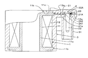
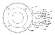
次に、本発明の電磁コイルユニットの実施形態について図面を参照して説明する。図1は実施形態の電磁コイルユニットの側面における部分断面図、図2は実施形態の電磁コイルユニットにおける端子部材の3面図、図3は実施形態の電磁コイルユニットにおけるボビンに端子部材を取り付けた状態を示す平面図、図4は実施形態の電磁コイルユニットにおけるボビンに端子部材を取り付けた状態を示す側断面図、図5は実施形態の電磁コイルユニットにおけるボビンに端子部材を取り付けた状態を示す正面図、図6は実施形態の電磁コイルユニットにおけるボビン及び端子部材に導線を巻回及び接続した状態を示す平面図、図7は実施形態の電磁コイルユニットにおけるボビン及び端子部材に導線を巻回及び接続した状態を示す側断面図、図8は実施形態の電磁コイルユニットにおけるボビン及び端子部材に導線を巻回及び接続した状態を示す側面図である。 Next, an embodiment of the electromagnetic coil unit of the present invention will be described with reference to the drawings. 1 is a partial cross-sectional view of a side surface of an electromagnetic coil unit of the embodiment, FIG. 2 is a three-side view of a terminal member in the electromagnetic coil unit of the embodiment, and FIG. 3 is a terminal member attached to a bobbin in the electromagnetic coil unit of the embodiment. FIG. 4 is a side sectional view showing a state in which the terminal member is attached to the bobbin in the electromagnetic coil unit of the embodiment, and FIG. 5 shows a state in which the terminal member is attached to the bobbin in the electromagnetic coil unit of the embodiment. FIG. 6 is a plan view showing a state in which the conducting wire is wound and connected to the bobbin and the terminal member in the electromagnetic coil unit of the embodiment, and FIG. 7 is a drawing of the conducting wire to the bobbin and the terminal member in the electromagnetic coil unit of the embodiment. FIG. 8 is a side sectional view showing the connected state, and FIG. 8 is a diagram showing the conductor coil wound around the bobbin and the terminal member in the electromagnetic coil unit of the embodiment. Is a side view showing the connection state.
この実施形態の電磁コイルユニットは、電磁コイル部1と、一対の端子部材2,2と、モールド樹脂部3とを有している。電磁コイル部1は、樹脂製のボビン11と、ボビン11にエナメル被覆された導線を巻回したコイル12とからなる。ボビン11は円筒状の筒部11aと、筒部11の両端に形成されたフランジ部11b,11bとからなり、コイル12はフランジ部11b,11bの間で筒部11aに導線を巻回したものである。また、端子部材2はボビン11の片側のフランジ部11bに圧入により固定され、この電磁コイル部1と端子部材2の一部とがモールド樹脂部3で封止されている。さらに、モールド樹脂部3は電磁コイル部1の軸(筒部の中心軸)と平行に伸びる円筒状のコネクタ部31を有している。
The electromagnetic coil unit of this embodiment includes an
図2に示すように、端子部材2は板金材のプレス加工及び曲げ加工により形成されたものであり、ボビン11に固定される内部端子部21と、内部端子部21の縁辺で折り曲げられた外部端子部22と、内部端子部21の端部に曲げ起こされた「曲げ起こし部」としてのヒュージング用の爪部23とを有している。内部端子部21と外部端子部22とは、それぞれが長手方向と短手方向とを有する長板状の形状である。
As shown in FIG. 2, the
そして、外部端子部22は、その長手方向の端部22Aにおいて内部端子部21に対して折り曲げられている。すなわち、外部端子部22は端部22Aにおいて内部端子部21に結合され、外部端子部22の短手方向(端部22Aの幅方向)が内部端子部21の長手方向と平行になっている。また、この外側端子部22の端部22Aは、内部端子部21の長手方向の縁辺の範囲内となっている。
The
図3及び図4に示すように、端子部材2は、内部端子部21の爪部23とは反対側の端部が、ボビン11のフランジ部11bに形成された嵌合孔11c内に圧入されている。すなわち、内部端子部21は嵌合孔11c内にその長手方向に圧入されてボビン11に固定されている。これにより、モールド樹脂部3で封止する成形時に、溶融樹脂の圧力により一対の端子部材2、2の相対位置がずれることが抑制される。また、図2に示すように、内部端子部21の爪部23側の端部21Aは、短手方向の幅を有する平坦な端面21Pとなっており、また、「曲げ起こし部」としての爪部23は端部21Aの板面と角度を成している。そして、内部端子部21の端面21Pに平行に爪部23の端面23Pも位置しており、上記の端面21Pと端面23Pとは概ね面一となっている。したがって、これらの端面21P,23Pの部分を押圧することにより、押圧力が内部端子部21の長手方向に作用し、この内部端子部21を嵌合孔11cに容易に圧入することができる。すなわち、端部21Aと爪部23とにより、この端部21Aにおける断面二次モーメントが大きくなっている。したがって、端部21A及び爪部23は上記長手方向の軸に対して変形しにくく、端面21P,23Pに加わる押圧力は上記長手方向の軸から殆どずれることなく作用するので、内部端子部21を嵌合孔11cに容易に圧入することができる。このことは内部端子部21と外部端子部22との結合部分についても同様である。
As shown in FIGS. 3 and 4, the
内部端子部21の長手方向の縁辺には短手方向に幅を拡げた膨出部21aが形成されている。そして、長手方向の縁辺の一部が膨出部21aと外部端子部22の端部22Aとに挟まれることにより第1の凹凸部2A1が形成されている。また、長手方向の縁辺の一部が外部端子部22の端部22Aと爪部23とに挟まれることによりと第2の凹凸部2A2が形成されている。図6及び図7に示すように、内部端子部21には、コイル12から引き出された導線12aが巻き付けられ、導線12aの端部が、爪部23の部分でヒュージング(抵抗溶接)により内部端子部21に接続されている。すなわち、導線12aは、内部端子部21のボビン11に対する固定端(嵌合孔11c側)とは反対側の端部にて内部端子部21に電気的に接続されている。
On the edge in the longitudinal direction of the
さらに、導線12aは、内部端子部21に巻き付けられるとき、第1の凹凸部2A1の段差にかかるように巻き付けられる。これにより、導線12aは内部端子部21の長手方向にずれるのを止めることができる。したがって、モールド樹脂部3で封止する成形時に、導線12aがずれたり切断したりするのを防止することができる。また、第2の凹凸部2A2の段差にも同様に導線12aがかかるように巻き付けられる。なお、この実施形態では、凹凸部は外部端子部及び爪部の一部により構成されているが、導線をずれ止めする凹凸部は、内部端子部の短手方向の幅を変化させるだけで形成するようにしてもよい。
Further, when the
以上のように構成され電磁コイルユニットでは、図1に示すように、端子部材2の外部端子部22が、モールド樹脂部3のコネクタ部31内に配置される。そして、図示しない雄コネクタがコネクタ部31内に嵌合されることにより、外部端子部22(端子部材2)を介して、コイル12に給電される。なお、この電磁コイルユニットが例えば電磁弁に装着されるときは、例えば、図1における下方側からボビン11の筒部11a内に電磁弁のプランジャ及び吸引子を内蔵するプランジャ装置が挿入される。
In the electromagnetic coil unit configured as described above, the
以上のように、実施形態の電磁コイルユニットによれば、コネクタ部31に配置される外部端子部22が内部端子部21の長手方向の縁辺の範囲内に結合されているので、内部端子部21のボビン11に対する固定端とは反対側端部である爪部23側の端部は、短手方向に幅を有する端部となる。したがって、この端部を押圧して内部端子部21をボビン11に圧入するなど簡単に組み付けることができる。また、外部端子部22は短手方向が内部端子部21の長手方向に平行になっているので、外部端子部22と内部端子部21との長手方向は略直角になり、コネクタ部31においてコネクタ接続される外部端子部22に長手方向に応力が加えられても、この応力は内部端子部21に対してねじりを与える方向であるので、この応力は内部端子部21の長手方向に分散されることとなる。これにより内部端子部21に対する応力の作用を低減できて、変形しにくくなる。
As described above, according to the electromagnetic coil unit of the embodiment, the
なお、実施形態では、導線12aと内部端子部21との接続をヒュージングにより行う例について説明したが、例えば内部端子21の爪部23を無くして、内部端子部21のボビン11に対する固定端とは反対側の端部22Aにて導線12aを巻き付け、この巻き付けた部分に半田付けを施すことで導線12aと内部端子部21との接続を行ってもよい。また、この半田付けを施す場合でも、内部端子が平板状で固定端とは反対側の端部が平坦であれば、前記同様に内部端子部21を嵌合孔11cに容易に圧入することができる。
In the embodiment, the example in which the connection between the
以上、本発明の実施の形態について図面を参照して詳述してきたが、具体的な構成はこれらの実施の形態に限られるものではなく、本発明の要旨を逸脱しない範囲の設計の変更等があっても本発明に含まれる。 As described above, the embodiments of the present invention have been described in detail with reference to the drawings. However, the specific configuration is not limited to these embodiments, and the design can be changed without departing from the scope of the present invention. Is included in the present invention.
1 電磁コイル部
11 ボビン
11a 筒部
11b フランジ部
11c 嵌合孔
12 コイル
12a 導線
2 端子部材
21 内部端子部
21A 端部
2A1 第1の凹凸部
2A2 第2の凹凸部
22 外部端子部
22A 端部
23 爪部(曲げ起こし部)
3 モールド樹脂部
31 コネクタ部
DESCRIPTION OF
3
Claims (7)
前記端子部材は、前記ボビンに固定されて前記導線に接続される内部端子部と前記モールド樹脂部のコネクタ部に配置される外部端子部とを一体にして構成され、前記内部端子部と前記外部端子部とは、それぞれが長手方向と短手方向とを有する長板状の形状であり、前記外部端子部の長手方向の端部がその短手方向を前記内部端子部の長手方向と平行にして該内部端子部の長手方向の縁辺の範囲内に結合された構造となっていることを特徴とする電磁コイルユニット。 An electromagnetic coil unit in which a conductive wire is wound around a bobbin and a part of a terminal member made of a conductive plate connected to the conductive wire of the electromagnetic coil portion is sealed with a mold resin portion. ,
The terminal member is configured integrally with an internal terminal portion fixed to the bobbin and connected to the conducting wire and an external terminal portion disposed in a connector portion of the mold resin portion, and the internal terminal portion and the external Each of the terminal portions has a long plate shape having a longitudinal direction and a short direction, and an end portion in the longitudinal direction of the external terminal portion makes its short direction parallel to the longitudinal direction of the internal terminal portion. The electromagnetic coil unit is structured to be coupled within a range of a longitudinal edge of the internal terminal portion.
Priority Applications (2)
| Application Number | Priority Date | Filing Date | Title |
|---|---|---|---|
| JP2018093118A JP6826552B2 (en) | 2018-05-14 | 2018-05-14 | Electromagnetic coil unit |
| CN201910334131.6A CN110491653B (en) | 2018-05-14 | 2019-04-24 | Electromagnetic coil unit |
Applications Claiming Priority (1)
| Application Number | Priority Date | Filing Date | Title |
|---|---|---|---|
| JP2018093118A JP6826552B2 (en) | 2018-05-14 | 2018-05-14 | Electromagnetic coil unit |
Publications (2)
| Publication Number | Publication Date |
|---|---|
| JP2019201039A true JP2019201039A (en) | 2019-11-21 |
| JP6826552B2 JP6826552B2 (en) | 2021-02-03 |
Family
ID=68545865
Family Applications (1)
| Application Number | Title | Priority Date | Filing Date |
|---|---|---|---|
| JP2018093118A Active JP6826552B2 (en) | 2018-05-14 | 2018-05-14 | Electromagnetic coil unit |
Country Status (2)
| Country | Link |
|---|---|
| JP (1) | JP6826552B2 (en) |
| CN (1) | CN110491653B (en) |
Families Citing this family (1)
| Publication number | Priority date | Publication date | Assignee | Title |
|---|---|---|---|---|
| JP7120275B2 (en) * | 2020-07-07 | 2022-08-17 | 株式会社デンソーエレクトロニクス | electromagnetic relay |
Citations (6)
| Publication number | Priority date | Publication date | Assignee | Title |
|---|---|---|---|---|
| JPS62126815U (en) * | 1986-01-31 | 1987-08-12 | ||
| JPH0563004U (en) * | 1992-01-30 | 1993-08-20 | 愛知電機株式会社 | Coil bobbins for electrical equipment |
| JP2000055513A (en) * | 1998-08-07 | 2000-02-25 | Saginomiya Seisakusho Inc | Condensation prevention structure in refrigeration cycle |
| JP2012156188A (en) * | 2011-01-24 | 2012-08-16 | Saginomiya Seisakusho Inc | Coil and solenoid valve using coil |
| JP2012164752A (en) * | 2011-02-04 | 2012-08-30 | Saginomiya Seisakusho Inc | Mold coil and solenoid valve using mold coil |
| JP2012523690A (en) * | 2009-04-09 | 2012-10-04 | イートン コーポレーション | Double-sided connector block |
-
2018
- 2018-05-14 JP JP2018093118A patent/JP6826552B2/en active Active
-
2019
- 2019-04-24 CN CN201910334131.6A patent/CN110491653B/en active Active
Patent Citations (6)
| Publication number | Priority date | Publication date | Assignee | Title |
|---|---|---|---|---|
| JPS62126815U (en) * | 1986-01-31 | 1987-08-12 | ||
| JPH0563004U (en) * | 1992-01-30 | 1993-08-20 | 愛知電機株式会社 | Coil bobbins for electrical equipment |
| JP2000055513A (en) * | 1998-08-07 | 2000-02-25 | Saginomiya Seisakusho Inc | Condensation prevention structure in refrigeration cycle |
| JP2012523690A (en) * | 2009-04-09 | 2012-10-04 | イートン コーポレーション | Double-sided connector block |
| JP2012156188A (en) * | 2011-01-24 | 2012-08-16 | Saginomiya Seisakusho Inc | Coil and solenoid valve using coil |
| JP2012164752A (en) * | 2011-02-04 | 2012-08-30 | Saginomiya Seisakusho Inc | Mold coil and solenoid valve using mold coil |
Also Published As
| Publication number | Publication date |
|---|---|
| JP6826552B2 (en) | 2021-02-03 |
| CN110491653A (en) | 2019-11-22 |
| CN110491653B (en) | 2021-09-14 |
Similar Documents
| Publication | Publication Date | Title |
|---|---|---|
| US9735517B1 (en) | Connector terminal, electric connector, and method of fabricating the connector terminal | |
| US9935529B2 (en) | Method for manufacturing laminated core for motor | |
| JP6084898B2 (en) | Connecting terminal | |
| JP6379403B2 (en) | Coaxial cable connector with core wire holding and fixing function | |
| US20210336520A1 (en) | Actuator | |
| CN102629510B (en) | Molded coil and solenoid controlled valve using the same | |
| JP6446725B2 (en) | Coaxial cable connector with improved crimp strength and impedance performance | |
| CN107039769A (en) | A kind of manufacture method of antenna assembly and the antenna assembly | |
| CN109980370B (en) | Connector | |
| JP2019201039A (en) | Electromagnetic coil unit | |
| US10895240B2 (en) | Ignition coil unit | |
| WO2019171914A1 (en) | Female terminal | |
| CN112600004A (en) | Terminal fitting | |
| CN104903614B (en) | Vibration-proof tie rod | |
| JP2016110711A (en) | Coaxial cable connector with external conductor shell with discontinuous portion | |
| US20150233654A1 (en) | Tank for heat exchanger | |
| JP2005500704A (en) | Sleeve-shaped hollow body for a piezo actuator module and method for manufacturing the hollow body | |
| US10770252B2 (en) | Magnetic system of electromagnetic relay | |
| CN102044790B (en) | Connector assembly and method of manufacturing the same | |
| JP5948839B2 (en) | Ignition coil for internal combustion engine | |
| JP7440549B2 (en) | Connecting terminal | |
| JP7708076B2 (en) | Reactor parts and their manufacturing method | |
| CN212783610U (en) | Battery cover plate assembly and battery | |
| JP7147803B2 (en) | Inductor component and manufacturing method thereof | |
| JP2015030500A (en) | Housing device |
Legal Events
| Date | Code | Title | Description |
|---|---|---|---|
| A621 | Written request for application examination |
Free format text: JAPANESE INTERMEDIATE CODE: A621 Effective date: 20191204 |
|
| A977 | Report on retrieval |
Free format text: JAPANESE INTERMEDIATE CODE: A971007 Effective date: 20200817 |
|
| A131 | Notification of reasons for refusal |
Free format text: JAPANESE INTERMEDIATE CODE: A131 Effective date: 20200825 |
|
| A521 | Request for written amendment filed |
Free format text: JAPANESE INTERMEDIATE CODE: A523 Effective date: 20201021 |
|
| TRDD | Decision of grant or rejection written | ||
| A01 | Written decision to grant a patent or to grant a registration (utility model) |
Free format text: JAPANESE INTERMEDIATE CODE: A01 Effective date: 20201222 |
|
| A61 | First payment of annual fees (during grant procedure) |
Free format text: JAPANESE INTERMEDIATE CODE: A61 Effective date: 20210115 |
|
| R150 | Certificate of patent or registration of utility model |
Ref document number: 6826552 Country of ref document: JP Free format text: JAPANESE INTERMEDIATE CODE: R150 |