JP2019201728A - sewing machine - Google Patents
sewing machine Download PDFInfo
- Publication number
- JP2019201728A JP2019201728A JP2018097330A JP2018097330A JP2019201728A JP 2019201728 A JP2019201728 A JP 2019201728A JP 2018097330 A JP2018097330 A JP 2018097330A JP 2018097330 A JP2018097330 A JP 2018097330A JP 2019201728 A JP2019201728 A JP 2019201728A
- Authority
- JP
- Japan
- Prior art keywords
- sewing
- intermediate presser
- height
- presser
- needle
- Prior art date
- Legal status (The legal status is an assumption and is not a legal conclusion. Google has not performed a legal analysis and makes no representation as to the accuracy of the status listed.)
- Granted
Links
Images




Classifications
-
- D—TEXTILES; PAPER
- D05—SEWING; EMBROIDERING; TUFTING
- D05B—SEWING
- D05B19/00—Program-controlled sewing machines
- D05B19/02—Sewing machines having electronic memory or microprocessor control unit
- D05B19/04—Sewing machines having electronic memory or microprocessor control unit characterised by memory aspects
- D05B19/08—Arrangements for inputting stitch or pattern data to memory ; Editing stitch or pattern data
-
- D—TEXTILES; PAPER
- D05—SEWING; EMBROIDERING; TUFTING
- D05B—SEWING
- D05B19/00—Program-controlled sewing machines
- D05B19/02—Sewing machines having electronic memory or microprocessor control unit
- D05B19/04—Sewing machines having electronic memory or microprocessor control unit characterised by memory aspects
- D05B19/10—Arrangements for selecting combinations of stitch or pattern data from memory ; Handling data in order to control stitch format, e.g. size, direction, mirror image
-
- D—TEXTILES; PAPER
- D05—SEWING; EMBROIDERING; TUFTING
- D05B—SEWING
- D05B19/00—Program-controlled sewing machines
- D05B19/02—Sewing machines having electronic memory or microprocessor control unit
- D05B19/12—Sewing machines having electronic memory or microprocessor control unit characterised by control of operation of machine
- D05B19/16—Control of workpiece movement, e.g. modulation of travel of feed dog
-
- D—TEXTILES; PAPER
- D05—SEWING; EMBROIDERING; TUFTING
- D05B—SEWING
- D05B27/00—Work-feeding means
- D05B27/02—Work-feeding means with feed dogs having horizontal and vertical movements
- D05B27/04—Work-feeding means with feed dogs having horizontal and vertical movements arranged above the workpieces
-
- D—TEXTILES; PAPER
- D05—SEWING; EMBROIDERING; TUFTING
- D05B—SEWING
- D05B29/00—Pressers; Presser feet
- D05B29/02—Presser-control devices
-
- D—TEXTILES; PAPER
- D05—SEWING; EMBROIDERING; TUFTING
- D05B—SEWING
- D05B29/00—Pressers; Presser feet
- D05B29/06—Presser feet
-
- D—TEXTILES; PAPER
- D05—SEWING; EMBROIDERING; TUFTING
- D05B—SEWING
- D05B29/00—Pressers; Presser feet
- D05B29/06—Presser feet
- D05B29/08—Presser feet comprising relatively-movable parts
-
- D—TEXTILES; PAPER
- D05—SEWING; EMBROIDERING; TUFTING
- D05B—SEWING
- D05B31/00—Workpiece holders or hold-downs in machines for sewing leather
-
- D—TEXTILES; PAPER
- D05—SEWING; EMBROIDERING; TUFTING
- D05D—INDEXING SCHEME ASSOCIATED WITH SUBCLASSES D05B AND D05C, RELATING TO SEWING, EMBROIDERING AND TUFTING
- D05D2205/00—Interface between the operator and the machine
- D05D2205/02—Operator to the machine
- D05D2205/04—Pedals
Landscapes
- Engineering & Computer Science (AREA)
- Textile Engineering (AREA)
- Computer Hardware Design (AREA)
- Microelectronics & Electronic Packaging (AREA)
- Sewing Machines And Sewing (AREA)
Abstract
【課題】適正な縫製を行う。【解決手段】縫い針108を上下動させる針上下動機構と、被縫製物C1からC4を保持枠で保持して移動させる移動機構と、保持枠に保持された被縫製物の上側で中押さえ29を上下動させる中押さえ装置1と、一連の縫製における針落ち位置を順番に定めた縫製データ71aに基づいて移動機構を制御する制御装置120とを備えるミシン100において、中押さえの高さを検出する高さ検出部49を備え、制御装置は、縫製データに従う縫製開始前に、当該縫製データに定められた一又は複数の針落ち位置において、保持枠に保持された被縫製物の上面まで中押さえを下降させて、高さ検出部により、中押さえの高さを検出し、被縫製物の厚さの適否を判定する。【選択図】図10PROBLEM TO BE SOLVED: To perform proper sewing. A needle up-and-down moving mechanism for moving a sewing needle up and down, a moving mechanism for holding and moving workpieces C1 to C4 by a holding frame, and an intermediate presser on an upper side of the workpiece held by the holding frame. In the sewing machine 100 including the intermediate presser device 1 for vertically moving 29, and the control device 120 for controlling the moving mechanism based on the sewing data 71a that sequentially determines the needle drop positions in a series of sewing, the height of the intermediate presser is The height detecting section 49 for detecting is provided, and the control device, before the start of sewing according to the sewing data, at one or a plurality of needle drop positions determined by the sewing data, reaches the upper surface of the sewn object held by the holding frame. The middle presser is lowered, and the height detection unit detects the height of the middle presser to determine whether the thickness of the sewing object is appropriate. [Selection diagram] Figure 10
Description
本発明は、中押さえを備えるミシンに関するものである。 The present invention relates to a sewing machine having an intermediate presser.
各針落ちごとに針落ち位置が定められた一乃至複数の任意の縫製パターンからなる一連の縫製について各針落ち位置を記録した縫製データに従って縫製を行うミシンとして、いわゆる、電子サイクル縫いミシンが知られている。
この電子サイクル縫いミシンは、被縫製物を保持する保持枠を水平面に沿って任意に移動位置決めして縫製を行うため、いわゆる、本縫いミシンのような縫製中に被縫製物を押さえたままの状態となる布押さえの替わりに中押さえを備えている。
中押さえは、保持枠で移動する被縫製物の妨げとならないように、針板に届かない高さで、縫い針よりも小さいストロークで上下動を行い、被縫製物のばたつきを押さえて、上昇する縫い針を被縫製物から円滑に引き抜くことができるようにしている(例えば、特許文献1参照)。
A so-called electronic cycle sewing machine is known as a sewing machine that performs sewing according to sewing data in which each needle drop position is recorded for a series of sewing patterns including one or a plurality of arbitrary sewing patterns in which a needle drop position is determined for each needle drop. It has been.
Since this electronic cycle sewing machine performs sewing by positioning and moving the holding frame for holding the sewing product along the horizontal plane, it keeps holding the sewing product during sewing such as a so-called main sewing machine. An intermediate presser is provided in place of the fabric presser.
The intermediate presser moves up and down with a stroke smaller than the sewing needle at a height that does not reach the needle plate so as not to interfere with the sewing product that moves with the holding frame, and raises the sewing product against flapping. The sewing needle to be pulled can be smoothly pulled out from the sewing product (for example, see Patent Document 1).
ところで、例えば、エアバッグのように、複数の被縫製物を重ねて縫製を行う場合に、針落ち位置によって縫い合わせる被縫製物の枚数が異なる場合がある。
この場合、保持枠は、予め定められた配置で、複数の被縫製物を重ねた状態で保持させて縫製が行われるが、保持枠にセットする際の被縫製物の配置を誤ったり、一部の被縫製物を重ね忘れたりすると、不良品が発生してしまう。
このような不良品の発生の抑止、低減が縫製の現場で求められていた。
By the way, for example, when a plurality of sewing products are overlapped and sewn, such as an airbag, the number of sewing products to be sewn may differ depending on the needle drop position.
In this case, the holding frame is sewn in a predetermined arrangement and held in a state where a plurality of articles to be sewn are overlapped. If you forget to overlap the part to be sewn, defective products will be generated.
Suppression and reduction of the occurrence of such defective products have been demanded at the sewing site.
本発明は、適正な縫製を行うことをその目的とする。 An object of the present invention is to perform proper sewing.
請求項1記載の発明は、ミシンにおいて、
縫い針を上下動させる針上下動機構と、
被縫製物を保持枠で保持して移動させる移動機構と、
前記保持枠に保持された被縫製物の上側で中押さえを上下動させる中押さえ装置と、
一連の縫製における針落ち位置を順番に定めた縫製データに基づいて前記移動機構を制御する制御装置とを備えるミシンにおいて、
前記中押さえの高さを検出する高さ検出部を備え、
前記制御装置は、前記縫製データに従う縫製開始前に、当該縫製データに定められた一又は複数の針落ち位置において、前記保持枠に保持された被縫製物の上面まで前記中押さえを下降させて、前記高さ検出部により、前記中押さえの高さを検出し、前記被縫製物の厚さの適否を判定することを特徴とする。
The invention according to
A needle up-and-down movement mechanism for moving the sewing needle up and down;
A moving mechanism for moving the work piece by holding it with a holding frame;
An intermediate pressing device that moves the intermediate presser up and down on the upper side of the sewing product held by the holding frame;
In a sewing machine comprising: a control device that controls the moving mechanism based on sewing data that sequentially defines a needle drop position in a series of sewing operations;
A height detection unit for detecting the height of the intermediate presser;
The control device lowers the intermediate presser to the upper surface of the sewing object held by the holding frame at one or a plurality of needle drop positions defined in the sewing data before starting sewing according to the sewing data. The height detection unit detects the height of the intermediate presser and determines whether or not the thickness of the sewing product is appropriate.
請求項2記載の発明は、請求項1に記載のミシンにおいて、
前記高さ検出部は、磁気センサーを含むことを特徴とする。
The invention according to
The height detection unit includes a magnetic sensor.
請求項3記載の発明は、請求項1又は2に記載のミシンにおいて、
前記縫製データは、被縫製物の厚さの情報を有し、
前記制御装置は、前記高さ検出部により検出した前記中押さえの高さを前記縫製データの被縫製物の厚さの情報と照合して、前記被縫製物の厚さの適否を判定することを特徴とする。
The invention according to
The sewing data includes information on the thickness of the sewing object,
The control device compares the height of the intermediate presser detected by the height detection unit with the information on the thickness of the sewing product in the sewing data, and determines whether the thickness of the sewing product is appropriate. It is characterized by.
請求項4記載の発明は、請求項3に記載のミシンにおいて、
前記縫製データに基づく一連の縫製は、複数の縫製パターンから構成され、
前記縫製データは、それぞれの前記縫製パターンごとに被縫製物の厚さの情報を有し、
前記制御装置は、それぞれの前記縫製パターンごとに、一箇所又は複数箇所について、前記保持枠に保持された被縫製物の上面まで前記中押さえを下降させて、前記高さ検出部により、前記中押さえの高さを検出し、前記被縫製物の厚さの適否を判定することを特徴とする。
The invention according to
A series of sewing based on the sewing data is composed of a plurality of sewing patterns,
The sewing data has information on the thickness of the sewing object for each of the sewing patterns,
The control device lowers the intermediate presser to the upper surface of the workpiece to be sewn held by the holding frame at one place or a plurality of places for each of the sewing patterns, and the height detecting unit The presser foot height is detected, and the suitability of the thickness of the sewing product is determined.
本発明は、縫製データに従う縫製開始前に、保持枠に保持された被縫製物の上面まで中押さえを下降させて、高さ検出部により、中押さえの高さを検出し、被縫製物の厚さの適否を判定することで不良品の発生を抑止、低減し、適正な縫製を行うことが可能となる。 In the present invention, before starting sewing according to the sewing data, the intermediate presser is lowered to the upper surface of the sewing product held by the holding frame, and the height of the intermediate presser is detected by the height detection unit. By determining whether or not the thickness is appropriate, the occurrence of defective products can be suppressed and reduced, and appropriate sewing can be performed.
[発明の実施形態の概要]
以下、図面を参照して、本発明に係るミシンの実施の形態について詳細に説明する。
なお、本実施形態では、ミシンとして電子サイクルミシンを例に説明する。
図1はミシン100の斜視図、図2は縫い針周辺の拡大斜視図である。
電子サイクルミシンは、複数枚重ねられた被縫製物を保持する保持枠を有し、その保持枠が縫い針に対し相対的に移動することにより、保持枠に保持された複数の被縫製物に所定の縫製データに基づく縫い目を形成するミシンである。
ここで、後述する縫い針108が上下動を行う方向をZ軸方向(上下方向)とし、これと直交する一の方向をX軸方向(左右方向)とし、Z軸方向とX軸方向の両方に直交する方向をY軸方向(前後方向)と定義する。
[Outline of Embodiments of the Invention]
Hereinafter, embodiments of a sewing machine according to the present invention will be described in detail with reference to the drawings.
In the present embodiment, an electronic cycle sewing machine will be described as an example of the sewing machine.
1 is a perspective view of the
The electronic cycle sewing machine has a holding frame that holds a plurality of articles to be sewn, and the holding frame moves relative to the sewing needle, so that a plurality of items to be sewn held by the holding frame can be obtained. The sewing machine forms a seam based on predetermined sewing data.
Here, the direction in which the
電子サイクルミシン100(以下、ミシン100という)は、図1に示すように、ミシンテーブルTの上面に備えられるミシン本体101と、ミシンテーブルTの下部に備えられミシン本体101を操作するためのペダルRと、ミシンテーブルTの上部に備えられ、ユーザによる入力操作を行うための操作パネル300等を備えている。
As shown in FIG. 1, an electronic cycle sewing machine 100 (hereinafter referred to as a sewing machine 100) includes a
[ミシンフレーム及び主軸]
図1、図2に示すように、ミシン本体101は、外形が側面視にて略コ字状を呈するミシンフレーム102を備えている。このミシンフレーム102は、ミシン本体101の上部をなし、Y軸方向に延びるミシンアーム部102aと、ミシン本体101の下部をなし、Y軸方向に延びるミシンベッド部102bと、ミシンアーム部102aとミシンベッド部102bとを連結する立胴部102cとを有している。
このミシン本体101は、ミシンフレーム102内に動力伝達機構が配置され、回動自在でY軸方向に延びる主軸及び下軸(いずれも図示略)を有している。主軸はミシンアーム部102aの内部において回転可能に支持され、下軸(図示省略)はミシンベッド部102bの内部において回転可能に支持されている。
[Sewing frame and spindle]
As shown in FIGS. 1 and 2, the sewing machine
The
主軸は、ミシンモーター2a(図7参照)に接続され、このミシンモーター2aにより回転力が付与される。また、下軸(図示省略)は、タイミングベルト及びギア(図示省略)を介して主軸と連結されており、主軸が回転すると、主軸の動力がタイミングベルト及びギアを介して下軸側へ伝達し、下軸が主軸の二倍速で回転するようになっている。
The main shaft is connected to a
下軸(図示省略)の前端には、釜装置(図示省略)が設けられている。主軸とともに下軸が回転すると、縫い針108と釜装置の外釜(図示省略)との協働により縫い目が形成される。
釜装置は、下軸の前端部に固定装備された外釜と、外釜の内側でボビンを要する内釜と、を備えている。釜装置の構成は周知のものと同様であるので、ここでは詳述しない。
A hook device (not shown) is provided at the front end of the lower shaft (not shown). When the lower shaft rotates together with the main shaft, a seam is formed by the cooperation of the
The hook device includes an outer hook fixedly provided at the front end portion of the lower shaft, and an inner hook that requires a bobbin inside the outer hook. Since the structure of the hook device is the same as a well-known one, it will not be described in detail here.
[針上下動機構]
ミシンアーム部102aの前端部には、縫い針108を下端部に保持した針棒108aが上下動可能に支持されている。ミシンアーム部102aの前端部内側において、主軸の前端に固定装備された針棒クランクと、針棒108aに固定装備された針棒抱きと、針棒クランクと針棒抱きと連結するクランクロッドとが設けられている。
[Needle vertical movement mechanism]
A
針棒クランクは、主軸と共に回転を行う。クランクロッドは、その一端部がY軸回りに回転可能に針棒クランクの回転円周上に連結され、他端部がY軸回りに針棒抱きに連結されている。従って、主軸がミシンモーター2aによって回転すると、クランクロッドの一端部が周回運動を行い、他端部には周回運動のZ軸方向成分となる上下動のみが伝わって、針棒108aに上下動を付与することができる。
即ち、上記ミシンモーター2a、主軸、針棒クランク、針棒抱き、クランクロッド、針棒108aは、縫い針108を上下動させる針上下動機構を構成している。
なお、針上下動機構は、周知の構成と同様のものなので、各構成についてはいずれも図示を省略している。
The needle bar crank rotates with the main shaft. One end of the crank rod is connected to the rotation circumference of the needle bar crank so as to be rotatable around the Y axis, and the other end is connected to the needle bar holder around the Y axis. Accordingly, when the main shaft is rotated by the
That is, the
In addition, since the needle up-and-down moving mechanism is the same as a well-known configuration, the illustration of each configuration is omitted.
[移動機構]
図1、図2に示すように、ミシンベッド部102b上には、針板110が配設されており、この針板110の上側に布保持部としての保持枠111が配置されている。
保持枠111は、ミシンアーム部102aの下側に配置された取付部材113に取り付けられており、その取付部材113にはミシンベッド部102b内に配置された図示しないベルト機構を介してX軸モーター76a及びY軸モーター77aが連結されている(図7参照)。
保持枠111は、被縫製物を挟持し、X軸モーター76a及びY軸モーター77aの駆動に伴い、保持した被縫製物を前後左右方向に移動させる。そして、保持枠111の移動と、縫い針108や釜(図示省略)の動作が連動することにより、被縫製物に所定の縫製データに記録された複数の針落ち位置に基づく縫い目が形成される。
[Movement mechanism]
As shown in FIGS. 1 and 2, a
The holding
The holding
上記保持枠111は、布押さえと下板とから構成されている。
また、取付部材113は、保持枠111の布押さえを昇降可能に支持しており、ミシンアーム部102a内に配置された布押さえモーター79aの駆動により、布押さえに昇降動作を付与する。布押さえは、下降移動により、下板との間で被縫製物を挟持して保持するようになっている。
そして、これら保持枠111、取付部材113、ベルト機構、X軸モーター76a、Y軸モーター77a及び布押さえモーター79a等が、被縫製物をX軸方向及びY軸方向に沿って任意に移動位置決めする移動機構として機能する。
The holding
Further, the
The holding
[ペダル]
ペダルRは、ミシン100を駆動させ、針棒108a及び縫い針108を上下動させたり、保持枠111を動作させたりするための操作ペダルとして作動する。
ペダルRには、ペダルRが踏み込まれたその踏み込み操作位置を検出するためのセンサーが組み込まれており、センサーからの出力信号がペダルRの操作信号として後述する制御装置120に入力される。
制御装置120は、その操作位置に応じた操作信号によって、ミシン100の駆動、その他の各動作を実行する制御を行う。
[pedal]
The pedal R operates as an operation pedal for driving the
The pedal R incorporates a sensor for detecting the depression operation position when the pedal R is depressed, and an output signal from the sensor is input to the
The
[操作パネル]
また、ミシン100には、ユーザによる操作入力を行うための操作パネル300が設けられており、操作パネル300に入力された各種データや操作信号は、後述する制御装置120に入力される。
なお、操作パネル300は、液晶表示パネルからなる表示部300bと当該表示部300bの表示画面上に設けられたタッチセンサー300cとを備えて構成されており、液晶表示パネルに表示される各種操作キー等をタッチ操作することにより、タッチパネルがタッチ指示された位置を検出し、検出した位置に応じた操作信号を後述する制御装置120に出力するようになっている。
[control panel]
In addition, the
The
[中押さえ装置]
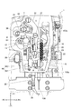
図3及び図4はミシンアーム部102a内の中押さえ装置1の正面図、図5は中押さえ装置1の一部の構成を示す分解斜視図、図6は中押さえ装置1の残る一部の構成を示す分解斜視図である。
中押さえ装置1は、ミシンアーム部102aの前端部において、縫い針108の上下動による被縫製物の浮き上がりを防止するために、針棒108aの上下動と連動して上下動し、縫い針108の周囲の被縫製物の上方へのばたつきを押さえる中押さえ29を有している。なお、中押さえ装置1の本体はミシンアーム部102aの内部に配設され、中押さえ29は、ミシンアーム部102aの前端部の下方に配置されている。そして、中押さえ29は、円形枠を有し、縫い針108がその内側に遊挿されている。
[Medium holding device]
3 and 4 are front views of the
The
中押さえ装置1は、図3〜図6に示すように、中押さえ29と、主軸の回転により上下動する縫い針108に合わせて中押さえ29を上下動させる中押さえ上下動機構M1と、中押さえ29の下降動作阻害時に中押さえ上下動機構M1に対する過剰負荷回避用の逃げ動作を可能とする過剰負荷回避機構M2と、中押さえ29を退避位置に上昇させる中押さえ退避機構M3と、ミシンモーター2aによる中押さえ29の上下動の動作範囲全体の高さを調節する中押さえ高さ調節機構M4と、を備えている。
As shown in FIGS. 3 to 6, the
[中押さえ装置:中押さえ上下動機構]
中押さえ上下動機構M1は、針上下動機構の主軸の回転から中押さえ29の上下動の動力を得ている。
即ち、中押さえ上下動機構M1は、主軸に設けられた偏心カムと、当該偏心カムを一端部で回転可能に保持するコンロッドと、往復回動を行うY軸方向に沿った揺動軸6と、揺動軸6からZ軸方向に向かって延出された揺動アームとからなる往復動作機構を備えている。
上記コンロッドの他端部は、揺動アームの延出端部に対してY軸回りに回動可能に連結されている。これにより、主軸が全回転を行うと、偏心カムによってコンロッドの一端部がY軸回りに周回動作を行い、他端部はX軸方向に沿って往動する。そして、揺動アームの延出端部にもX軸方向に沿った往動が伝わり、当該揺動アームを軸支する揺動軸6は主軸の回転と同じ周期で往復回動を行う。
なお、偏心カムを用いた往復動作機構は、周知の機構なので、揺動軸6を除いた各構成については図示を省略している。
[Medium presser: Middle presser vertical movement mechanism]
The intermediate presser vertical movement mechanism M1 obtains power for moving the
That is, the intermediate presser vertical movement mechanism M1 includes an eccentric cam provided on the main shaft, a connecting rod that rotatably holds the eccentric cam at one end portion, and a
The other end of the connecting rod is connected to the extending end of the swing arm so as to be rotatable about the Y axis. As a result, when the main shaft makes a full rotation, one end of the connecting rod rotates around the Y axis by the eccentric cam, and the other end moves forward along the X-axis direction. The forward movement along the X-axis direction is also transmitted to the extending end portion of the swing arm, and the
Since the reciprocating mechanism using the eccentric cam is a well-known mechanism, the illustration of each component excluding the
さらに、揺動軸6の他端部には、図6に示すように、中押さえ29の上下方向D1の移動量を調節する中押さえ調節腕7の基端部が固定されている。中押さえ調節腕7にはカム溝7aが形成されている。このカム溝7aは弧状の長孔になっており、このカム溝7aの所望の位置で第1リンク8の上端部が調節ナット9と段ねじ10によりY軸回りに軸支されている。第1リンク8の上端部の固定位置は揺動軸6の中心に対して接離移動調節可能であり、中心からの距離に比例して第1リンク8に付与する往復動作量、即ち、中押さえ29の上下動作量を増減調節することができる。
Further, as shown in FIG. 6, the base end portion of the intermediate
第1リンク8の下端部は、図6に示すように、第2リンク11の長手方向略中間部に段ねじ12よりY軸回りに回動自在に連結されている。ここで、調節ナット9が係合するカム溝7aは、中押さえ29が上下往復運動の下死点にあるときに、段ねじ12の軸心を中心とした円弧の一部となるように形成されている。つまり、カム溝7aにおける第1リンク8の位置調節を行うことで、中押さえ29の下死点位置を不動状態のままストローク調節を行うことができる。
As shown in FIG. 6, the lower end of the
そして、第2リンク11の左端部は、後述する位置決めリンク13に対して段ネジ18によりY軸回りに軸支されている。
また、第2リンク11の右端部は、図6に示すように、第3リンク20の上端部に段ねじ21によりY軸回りに回動自在に連結されている。第3リンク20の下端部には、第4リンク22の上端部が段ねじ23によりY軸回りに回動自在に連結されている。
The left end portion of the
Further, as shown in FIG. 6, the right end portion of the
第4リンク22の下端部には、リンク中継板25が段ねじ26によりY軸回りに連結されている。リンク中継板25には中押さえ棒抱き27が固定されており、中押さえ棒抱き27にはZ軸方向に延びる中押さえ棒28が保持されている。中押さえ棒28の下端部には、縫製時に被縫製物の上昇を抑える中押さえ29が取り付けられている。中押さえ棒28には中押さえ棒抱き27が固定装備されている。そして、中押さえ棒28の上側には、ボルト31、ナット32及びばね支軸301に支持された押圧バネ30が設けられ、当該押圧バネ30により、中押さえ棒28及び中押さえ29が常時下方に押圧されている。
A
そして、本実施形態では、往復動作機構、揺動軸6、中押さえ調節腕7、第1リンク8、第2リンク11、第3リンク20、第4リンク22、中押さえ棒抱き27、中押さえ棒28、押圧バネ30、ボルト31、ナット32及び段ねじ37等により、中押さえ上下動機構M1が構成されている。
In this embodiment, the reciprocating mechanism, the
[中押さえ装置:中押さえ高さ調節機構]
前述した段ねじ23は、角駒33及び案内部材34と共に第3リンク20と第4リンク22とを連結している。すなわち、第4リンク22の前側には案内部材34が設けられ、角駒33は案内部材34の長手方向に沿って滑動可能に支持されている。
[Medium presser: Middle presser height adjustment mechanism]
The above-mentioned
案内部材34は、長手方向が概ねZ軸方向に沿った状態で、その上端部34tが段ねじ35によりミシン筐体(ミシンフレーム102)にY軸回りに回動自在に支持されている。従って、案内部材34は、その下端部が左右に揺動し、その長手方向を左右に傾けることができる。
案内部材34の下端部近傍には、その長手方向に沿って長尺な長孔34aが形成されている。この長孔34aは、内側に角駒33がスライド可能に嵌めこまれている。このため、案内部材34は、角駒33を介して、第3リンク20と第4リンク22の連結部を長孔34aに沿って移動可能としている。
The
In the vicinity of the lower end portion of the
また、図6に示すように、案内部材34には、当該案内部材34をそのX軸方向に揺動させる移動リンク36の右端部が、段ねじ37により長孔34aの上部近傍にY軸回りに回動自在に連結されている。移動リンク36の左端部には偏心カム38が連結されており、この偏心カム38は可変軸39の前端部に固定支持されている。
可変軸39は、Y軸方向に沿って配置され、ベアリング40によってY軸回りに回転可能に支持されている。また、可変軸39の途中部分にはかさ歯車41、後端部には従動歯車391が固定装備されている。
Further, as shown in FIG. 6, the
The
一方、可変軸39の後方には、出力軸を前方に向けた中押さえモーター42が配置されており、その出力軸は主動歯車421が固定装備されている。この主動歯車421は、可変軸39の従動歯車391に噛合しており、中押さえモーター42の駆動により、可変軸39を回転させることができる。
On the other hand, an
つまり、中押さえモーター42の駆動が、可変軸39、偏心カム38、移動リンク36の順に伝達され、移動リンク36が案内部材34を回動させるようになっている。
中押さえモーター42は、正逆方向に回転駆動させることができ、その回動量及び駆動のタイミングが制御装置120により制御可能となっている。
また、中押さえモーター42には、その出力軸の軸角度を検出するエンコーダ81が併設されている。このエンコーダ81は、いわゆる、アブソリュート型であり、出力軸の軸角度の絶対的な位置を検出可能とし、原点センサーを必要としない。なお、エンコーダ81として、インクリメンタル型を使用して、原点センサー及びパルスカウンタを有する構成としてもよい。
そして、中押さえモーター42、主動歯車421、従動歯車391、可変軸39、偏心カム38、移動リンク36、案内部材34及び角駒33等が、ミシンモーター2aによる中押さえ29の上下動の動作範囲全体の高さを上下方向に推移させる中押さえ高さ調節機構M4として機能する。
That is, the driving of the
The
The
The intermediate
[中押さえ装置:過剰負荷回避機構]
前述した位置決めリンク13は、その中央部近傍で段ねじ14によりミシン筐体としてのミシンフレーム102にY軸回りに回動自在に取り付けられている。そして、Y軸方向から見た段ねじ14の位置は、中押さえ29が下死点にあるときの段ねじ12の位置と一致する。
[Medium presser: Overload avoidance mechanism]
The
位置決めリンク13の右端部にはばね掛け13aが形成されており、当該ばね掛け13aには引っ張りばね16の上端部が連結され、引っ張りばね16の下端部は、ミシンフレーム102に固定されているばね掛15に連結されている。従って、位置決めリンク13の右端部は下方に常に張力を受けている。
A
そして、位置決めリンク13はその後面側に一体的にストッパ17が重ねて装備されており、当該ストッパ17の左端部の上方には規制部材19が当接している。このため、位置決めリンク13は、右端部に付与された引っ張りばね16からの下方の張力によって、その左端部がストッパ17を介して規制部材19に圧接した状態となり、段ねじ14を中心とする時計方向の回動が規制された状態にある。
The
これにより、中押さえ29の高さを低く調節し過ぎたために、中押さえ29の下降時に被縫製物に圧接した場合に、第2リンク11を支持する位置決めリンク13の右端部が引っ張りばね16に抗して持ち上げられ、第1リンク8から第2リンク11に付される下方の押圧力を逃がすことができる。
つまり、引っ張りばね16、ばね掛け15、ストッパ17、位置決めリンク13、規制部材19が、中押さえ29の下降動作阻害時に中押さえ上下動機構M1に対する過剰負荷回避用の逃げ動作を可能とする過剰負荷回避機構M2として機能する。
Accordingly, since the height of the
In other words, the
[中押さえ装置:中押さえ退避機構]
図5に示すように、かさ歯車41には、かさ歯車43が歯合されており、中押さえモーター42の駆動を可変軸39の軸方向と直交する方向D4を中心とする回転方向に出力することができるようになっている。かさ歯車43の右方にはベアリング44、中押さえ昇降カム45等がX軸方向に沿った同軸上に連結されている。
[Intermediate presser: intermediate presser retracting mechanism]
As shown in FIG. 5, a
中押さえ昇降カム45は、外周カムである。中押さえ昇降カム45の外周は、軸回り180°の範囲は外径が一定であり(以下、維持部という)、残りの一部の角度範囲は外径が漸増する形状(以下、変化部という)となっている。
この中押さえ昇降カム45は、中押さえ29を縫製終了後の退避位置に上昇させる中押さえ上げ部材46の一端部46aを上下に昇降させるものであり、当該中押さえ昇降カム45の外周には、中押さえ上げ部材46を回動させるZ軸方向に沿った梃子部材461の上端部に設けられた円筒状のコロ47が摺接する。
The intermediate presser raising / lowering
The intermediate presser raising / lowering
梃子部材461は、Z軸方向の中間部において、ピン462によって軸支され、X軸回りに回動可能となっている。
そして、梃子部材461の下端部は、Y軸方向に沿った伝達リンク463の後端部にX軸回りに回動可能に連結されている。
また、梃子部材461の下端部近傍には、前方に張力を付与する引っ張りばね464の後端部が連結されており、これによって、梃子部材461の上端部のコロ47が中押さえ昇降カム45の外周に圧接させられている。
The
And the lower end part of the
In addition, a rear end portion of a
中押さえ上げ部材46はX軸方向から見て略L字状を呈しており、屈曲部においてピン48によって軸支され、X軸回りに回動可能となっている。
リンク中継板25を下から係止して中押さえ29を上昇させる中押さえ上げ部材46の一端部46aは、屈曲部から前方に延出されている。また、屈曲部から上方に延出された中押さえ上げ部材46の他端部46bは、伝達リンク463の前端部にX軸回りに回動可能に連結されている。
The intermediate
One
上記構成により、中押さえモーター42が駆動すると、中押さえ昇降カム45が回動し、中押さえ昇降カム45の維持部にコロ47が摺接しているときに、中押さえ高さ調節機構M4において中押さえ29の上下動の動作範囲全体の高さを上下方向に推移させる。そして、中押さえ昇降カム45の変化部にコロ47が摺接しているときに、梃子部材461の下端部が引っ張りばね464に抗して後方に回動し、伝達リンク463を介して中押さえ上げ部材46に時計方向の回動を付勢し、その一端部46aにより中押さえ29を上方の退避位置まで引き上げる。
つまり、かさ歯車41,43、中押さえ昇降カム45、コロ47、梃子部材461、伝達リンク463、引っ張りばね464及び中押さえ上げ部材46等により、中押さえ退避機構M3が構成されている。
With the above configuration, when the
That is, the intermediate presser retracting mechanism M3 is configured by the bevel gears 41 and 43, the intermediate presser raising / lowering
[高さ検出部]
ミシン100は、中押さえ29の高さを検出する高さ検出部49を備えている。この高さ検出部49は、図3及び図4に示すように、前述した中押さえ29及び中押さえ棒28と一体的に上下動を行うリンク中継板25に固定装備された被検出体としての磁石491と、ミシンアーム部102aの前端部におけるリンク中継板25の左側近傍に装備された磁気センサー492とを備えている。
磁気センサー492は、Z軸方向について磁気強度の大きさの変化を検出可能であり、これによって磁石491の高さを検出することができる。
磁気センサー492としては、コイル、ホール素子、磁気抵抗効果素子、磁気インピーダンス素子等を使用することができる。
[Height detection unit]
The
The
As the
[縫製時における中押さえの動作]
次に、上記構成を有する中押さえ装置1の中押さえ上下動機構M1の動作について説明する。
ミシンモーター2aの駆動により主軸が回転すると、往復動作機構により、揺動軸6は往復回動を行う。これにより、中押さえ調節腕7が上下に揺動し、第1リンク8を介して、第2リンク11の右端部は第3リンク20と第4リンク22の直列方向D2に揺動し、第3リンク20及び第4リンク22は、その直列方向(上下方向)D2に揺動する。これに伴い、中押さえ棒28は上下方向D1に沿って上下方向に移動するため、中押さえ29は縫い針108の上下動に同期して上下方向に往動する。
[Operation of intermediate presser during sewing]
Next, the operation of the intermediate presser vertical movement mechanism M1 having the above configuration will be described.
When the main shaft is rotated by driving the
[中押さえ装置による中押さえの高さの調節動作]
次に、上記構成を有する中押さえ装置1の中押さえ高さ調節機構M4による中押さえ29の高さの調節動作について説明する。
中押さえモーター42の駆動は、主動歯車421及び従動歯車391を介して可変軸39に伝達され、可変軸39及び偏心カム38が回動し、案内部材34は、概ねX軸方向に沿って揺動する。これにより、角駒33を介して第3リンク20と第4リンク22は、連結部において屈曲角度が変化して中押さえ29の高さが変動する。このとき、角駒33は、案内部材34の長孔34aに沿って上下動を行うので、中押さえ29は上下動を行いつつ、中押さえ29の上下動の動作範囲全体の高さが変動する。従って、中押さえ高さ調節機構M4により、中押さえ29の上下動における下死点の高さを調節することができる。
[Adjustment operation of intermediate presser height by intermediate presser]
Next, the operation of adjusting the height of the
The driving of the
[ミシンの制御系:制御装置]
図7はミシン100の制御系を示すブロック図である。
ミシン100は、上述した各部の動作を制御するための動作制御手段としての制御装置120を備えている。そして、制御装置120は、縫製プログラム70a及び厚さ検出制御プログラム70bが格納されたプログラムメモリ70と、縫製データ71a及び各種の設定情報(図示略)を記憶した記憶手段としてのデータメモリ71と、プログラムメモリ70内の各プログラム70a,70bを実行するCPU73とを備えている。
[Sewing machine control system: control device]
FIG. 7 is a block diagram showing a control system of the
The
また、CPU73は、インターフェイス300aを介して操作パネル300に接続されている。かかる操作パネル300は、各種画面や入力ボタンを表示する表示部300bと表示部300bの表面に設けられその接触位置を検知するタッチセンサー300cとを有しており、各種情報の入出力手段として機能する。操作パネル300で用いられる入力ボタンや入力スイッチはいずれも、表示部300bで表示され、タッチセンサー300cで入力が検知されることで押下式のボタンやスイッチと同等に機能するものである。
また、操作パネル300は、縫製データ71aの設定パラメータを任意に設定する機能や複数ある縫製データ71aの中から所望のデータを選択する機能も有している。
The
The
また、CPU73は、インターフェイス75を介して、ミシンモーター2aを駆動するミシンモーター駆動回路75bに接続され、ミシンモーター2aの回転を制御する。なお、ミシンモーター2aはエンコーダ2bを備えている。
なお、ミシンモーター2aには、例えば、サーボモーターを適用することができる。
The
For example, a servo motor can be applied to the
また、CPU73は、インターフェイス76及びインターフェイス77を介して、縫製すべき被縫製物を保持する保持枠111に備えられるX軸モーター76a及びY軸モーター77aをそれぞれ駆動するX軸モーター駆動回路76b及びY軸モーター駆動回路77bが接続され、保持枠111のX軸方向及びY軸方向の動作を制御する。
Further, the
また、CPU73は、インターフェイス78を介して、ミシンモーター2aによる中押さえの上下動の上死点位置と下死点高さ位置を調節する中押さえモーター42を駆動する中押さえモーター駆動回路78bが接続され、中押さえ装置1の動作を制御する。なお、前述したように、中押さえモーター42の出力軸にはモーター軸角度検出手段としてのエンコーダ81が設けられている。
Further, the
また、CPU73は、インターフェイス79を介して、布押さえ(図示省略)を上下に移動する布押さえモーター79aを駆動する布押さえモーター駆動回路79bが接続され、布押さえの動作を制御する。
なお、X軸モーター76a及びY軸モーター77a、中押さえモーター42、布押さえモーター79aには、例えば、ステッピングモーターを適用することができる。
Further, the
For example, a stepping motor can be applied to the
また、CPU73は、インターフェイス492aを介して、磁気センサー492が接続され、中押さえ29の高さを検出することができる。
Further, the
[縫製データ]
図8は縫製の一例を示す被縫製物の平面図である。
図8の例のように、一部の大きさや形状が異なる複数の被縫製物C1〜C4を重ねて縫製を行う場合、縫製範囲の針落ち位置に応じて、被縫製物の枚数が異なる区間が存在する。
例えば、図9は上記のような被縫製物の枚数が異なる区間が存在する場合の縫製データ71aの一例を示している。
この縫製データ71aは、図8の第1〜第3の縫製パターンP1〜P3を含む一連の縫製を行うためのデータである。縫製パターンP1は二枚の被縫製物C1,C2に縫製を行い、縫製パターンP2は三枚の被縫製物C1〜C3に縫製を行い、縫製パターンP3は四枚の被縫製物C1〜C4に縫製を行う。
[Sewing data]
FIG. 8 is a plan view of a sewing product showing an example of sewing.
As shown in the example of FIG. 8, when the sewing is performed by overlapping a plurality of sewing products C1 to C4 having different sizes and shapes, the number of the sewing products varies depending on the needle drop position in the sewing range. Exists.
For example, FIG. 9 shows an example of the
The
縫製データ71aは、縫製中に実行される各種の動作、例えば、「中押さえの高さ変更」、「針落ち位置への被縫製物の移動」、「糸切り」等の指令が実行順に記録されている。なお、糸切り装置の図示は省略している。
中押さえ29は、上下動の下死点高さが重ねられた被縫製物の高さに略一致する高さとなるように高さ調節が行われる。
従って、縫製データ71aには、縫製パターンP1の縫製開始時に、中押さえ29の下死点高さが被縫製物C1,C2からなる二枚分の高さとなるように、「中押さえの高さ変更」の指令が設定されている。そして、それ以降は、縫製パターンP1を縫うように順番に針落ち位置を示した被縫製物の移動指令が設定されている。
また、縫製パターンP2の縫製開始時には、中押さえ29の下死点高さが被縫製物C1〜C3からなる三枚分の高さとなるように、「中押さえの高さ変更」の指令が設定され、それ以降は、縫製パターンP2を縫うように順番に針落ち位置を示した被縫製物の移動指令が設定されている。
さらに、縫製パターンP3の縫製開始時には、中押さえ29の下死点高さが被縫製物C1〜C4からなる四枚分の高さとなるように、「中押さえの高さ変更」の指令が設定され、それ以降は、縫製パターンP3を縫うように順番に針落ち位置を示した被縫製物の移動指令が設定されている。
The
The height of the
Accordingly, in the
In addition, at the start of sewing of the sewing pattern P2, a command for "change the height of the intermediate presser" is set so that the bottom dead center height of the
Furthermore, at the start of sewing of the sewing pattern P3, a command for "change of the height of the intermediate presser" is set so that the bottom dead center height of the
[縫製制御]
ミシン100の制御装置120のCPU73は、プログラムメモリ70内の縫製プログラム70aに基づいて、縫製データ71aに定められた指令を順番に実行することにより、各縫製パターンP1〜P3の縫製を行う縫製制御を実行する。
例えば、図9の縫製データ71aに基づいて縫製を行う場合、CPU73は、まず、縫製パターンP1で縫製を行うために、上下動を行う中押さえ29の下死点の高さが設定値「6」(被縫製物二枚分の高さ)となるように中押さえモーター42を制御する。
その後は、CPU73は、ミシンモーター2aの駆動を開始すると共に、毎針の規定の主軸角度で縫製パターンP1を順番に辿るようにX軸モーター76a及びY軸モーター77aを制御して各被縫製物を移動させる。そして、縫製パターンP1の最終針落ち位置に針落ちを終えると、糸切りを実行する。
そして、CPU73は、縫製パターンP2で縫製を行うために、中押さえ29の下死点の高さを設定値「9」(被縫製物三枚分の高さ)に調節し、縫製パターンP2の全ての針落ち位置に針落ちを行い、糸切りを実行する。
同様に、CPU73は、縫製パターンP3で縫製を行うために、中押さえ29の下死点の高さを設定値「12」(被縫製物四枚分の高さ)に調節し、縫製パターンP3の全ての針落ち位置に針落ちを行い、糸切りを実行する。
このように、縫製プログラム70aを実行するCPU73は、縫製データ71aに定められた指令を読み込んで順番に実行することで、ミシン100の各構成を制御して、縫製データに含まれた縫製パターンに従って縫製を実行する。
[Sewing control]
The
For example, when sewing is performed based on the
Thereafter, the
Then, the
Similarly, in order to perform sewing with the sewing pattern P3, the
In this way, the
[厚さ検出制御]
ミシン100の制御装置120のCPU73は、プログラムメモリ70内の厚さ検出制御プログラム70bに基づいて、縫製プログラム70aによる縫製を実行する直前に縫製パターンP1〜P3のそれぞれの一部の針落ち位置に対して被縫製物の枚数を確認する厚さ検出制御を実行する。
[Thickness detection control]
Based on the thickness
前述した縫製データ71aでは、縫製パターンP1〜P3ごとに中押さえ29の下死点高さが設定されている。この縫製データ71aに設定されている中押さえ29の下死点高さは、重ねられた被縫製物の一番上の被縫製物の上面の高さに略一致する高さに設定される。従って、縫製データ71aに含まれる中押さえ29の下死点高さを被縫製物の厚さの情報として被縫製物の上面高さ、即ち、被縫製物が何枚重ねられているかを認識することができる。
In the above-described
図9に示すように、縫製データ71aの中押さえ29の下死点高さは、縫製パターンP1〜P3ごとに設定されているので、各縫製パターンP1〜P3のいずれかの針落ち位置において、保持枠111に保持された被縫製物に対して被縫製物の厚さを検出し、検出された厚さと前述した縫製データ中の中押さえ29の下死点高さと比較することにより、被縫製物が適正な枚数で重ねられているか(被縫製物C1〜C4のいずれかの入れ忘れ等が生じていないか)を判定することができる。
As shown in FIG. 9, since the bottom dead center height of the
被縫製物の厚さは、中押さえ29の高さを検出する磁気センサー492により検出することができる。
具体的には、制御装置120のCPU73は、各縫製パターンP1〜P3のいずれかの針落ち位置、例えば、各縫製パターンP1〜P3における第一針目の針落ち位置に保持枠111を位置決めする。
そして、中押さえモーター42を中押え29が下方へ移動するように駆動させ、中押さえ29は底部が被縫製物に接するまで下降する。従って、このときの中押さえ29の高さを磁気センサー492により検出することにより、被縫製物の厚さを求めることができる。
被縫製物のバラつきを考慮して、縫製データ71aに定められた中押さえ29の下死点高さに対して、所定の係数を加減算した数値範囲を適正範囲とし、この適正範囲に磁気センサー492により検出された中押さえ29の高さが入らない場合には、被縫製物が適正な枚数ではない状態、つまり、一部の被縫製物の入れ忘れ或いは一部の被縫製物にズレが生じているものとして、操作パネル300の表示部300bに、被縫製物が適正にセットされていない旨の報知表示を行い、縫製動作を開始しないで中止状態とする。
The thickness of the workpiece can be detected by a
Specifically, the
Then, the
In consideration of the variation of the sewing object, a numerical range obtained by adding / subtracting a predetermined coefficient to the bottom dead center height of the
[厚さ検出制御プログラムによる処理]
厚さ検出制御プログラム70bによりCPU73が行う制御について図10のフローチャートに基づいて詳細に説明する。
まず、保持枠111に被縫製物C1〜C4がセットされた状態で、縫製開始の指示が入力されると(ステップS1)、制御装置120のCPU73は、縫製データ71aの読み込みを開始する(ステップS3)。
即ち、CPU73は、縫製データ71aに記録されている各種の縫製動作の指令を順番に読み込み、「中押さえの高さ変更」の指令を探索する(ステップS5)。
[Processing by thickness detection control program]
Control performed by the
First, when an instruction to start sewing is input in a state where the sewing products C1 to C4 are set in the holding frame 111 (step S1), the
That is, the
そして、「中押さえの高さ変更」の指令が見つけられた場合には(ステップS5:YES)、CPU73は、「中押さえの高さ変更」の指令の直近に設定されている「針落ち位置への被縫製物の移動」の指令に定められた針落ち位置を読み込み、当該針落ち位置に保持枠111が位置決めされるようにX軸モーター76a及びY軸モーター77aを制御する(ステップS7)。
When a command for “change in the height of the intermediate presser” is found (step S5: YES), the
さらに、中押さえモーター42を中押え29が下方へ移動するよう駆動させ、中押さえ29を被縫製物の上面に当接するまで下降させる(ステップS9)。
被縫製物に当接した時の中押さえ29の高さを磁気センサー492により検出し(ステップS11)、この検出高さが「中押さえの高さ変更」の指令に定められた中押さえ高さの設定値に基づく適正範囲内であるか否かを判定して、検出高さに基づく被縫製物の高さ(枚数)が適正か否かを判定する(ステップS13)。
Further, the
The height of the
上記判定において、中押さえ29の検出高さが中押さえ高さの適正範囲内である場合には(ステップS13:YES)、ステップS5に処理を戻して、次の「中押さえの高さ変更」の指令を探索する。
また、中押さえ29の検出高さが中押さえ高さの適正範囲内ではない場合には(ステップS13:NO)、CPU73は、操作パネル300の表示部300bに、被縫製物が適正にセットされていない旨の報知表示を行い、縫製動作を開始しないで中止状態とする(ステップS15)。
In the above determination, when the detected height of the
If the detected height of the
また、ステップS5において、縫製データ71a中の全ての指令が探索完了した場合には、縫製プログラム70aに基づく縫製制御に処理が引き継がれて、縫製制御が実行される。
In step S5, when all the commands in the
[実施形態の効果]
以上のように、ミシン100では、中押さえ29の高さを検出する高さ検出部49を備え、制御装置120は、厚さ検出制御により、縫製データ71aに従う縫製開始前に、保持枠111に保持された一番上の被縫製物の上面まで中押さえ29を下降させて、高さ検出部49により、中押さえ29の高さを検出し、被縫製物の厚さの適否を判定している。
このため、被縫製物C1〜C4を複数重ねて縫製する場合等に、一部の被縫製物C1〜C4のいずれかについて保持枠111にセットし忘れた場合やいずれかの被縫製物C1〜C4についてズレを生じていた場合等に、高さ検出部49によって検出することが可能である。
これにより、一部の被縫製物C1〜C4のいずれかについての保持枠111へのセットし忘れや被縫製物C1〜C4のズレを効果的に検出することが可能となり無駄な縫製を低減することが可能となる。
[Effect of the embodiment]
As described above, the
For this reason, when a plurality of sewing products C1 to C4 are stacked and sewn, for example, when some of the sewing products C1 to C4 are forgotten to be set on the holding
As a result, it is possible to effectively detect forgetting to set one of some of the sewn items C1 to C4 to the holding
また、高さ検出部49は、磁気センサー492を含む構成なので、光学的に検出する場合に比べて、ミシンフレーム102内の糸くず、埃や塵芥、潤滑油の汚れなどの影響を受けにくく、良好な被縫製物の厚さ検出を安定的に行うことが可能となる。
Further, since the
また、縫製データ71aは、被縫製物C1〜C4の厚さの情報として「中押さえの高さ変更」の指令を含んでいる。
これにより、被縫製物C1〜C4の厚さの情報を別途用意する必要がなく、処理の簡略化、情報記憶容量の低減を図ることが可能となる。
Further, the
Accordingly, it is not necessary to separately prepare information on the thicknesses of the sewing objects C1 to C4, and it becomes possible to simplify the processing and reduce the information storage capacity.
また、縫製データ71aに基づく一連の縫製は、複数の縫製パターンP1〜P3から構成され、縫製データ71aは、それぞれの縫製パターンP1〜P3ごとに被縫製物の厚さの情報として「中押さえの高さ変更」の設定情報を有し、制御装置120は、それぞれの縫製パターンP1〜P3ごとに、一部の針落ち位置(各縫製パターンの第一針目の針落ち位置)について、保持枠111に保持された被縫製物の上面まで中押さえ29を下降させて、高さ検出部49により、中押さえ29の高さを検出し、被縫製物の厚さの適否を判定している。
このため縫製に要する縫製データ71aを利用して、各被縫製物C1〜C4の厚さ(枚数)の適否を判定することができ、既存のミシン100を利用して被縫製物C1〜C4のいずれかについての保持枠111へのセットし忘れや被縫製物C1〜C4のズレを効果的に検出することが可能となる。また、適正な被縫製物の枚数や厚さのデータを別途記憶する記憶部を新たに設ける必要がない。
A series of sewing operations based on the
For this reason, it is possible to determine the suitability of the thickness (number of sheets) of the respective sewing products C1 to C4 using the
[その他]
前述した厚さ検出制御プログラム70bに基づく厚さ検出制御では、適正な被縫製物の厚さの情報を縫製データ71a中の中押さえ29の高さの設定値から取得しているが、縫製データ71aとは別に、被縫製物の厚さの情報を用意してもよい。
また、それぞれの縫製パターンP1〜P3に対して一箇所のみで被縫製物の厚さ検出を行っているが、それぞれの縫製パターンP1〜P3に対して複数箇所で被縫製物の厚さ検出を行ってもよい。
さらに、縫製データ71aでは、各縫製パターンP1〜P3ごとに被縫製物の厚さが個別に設定され、それぞれの縫製パターンP1〜P3を構成する各針落ち位置では被縫製物の厚さが一定となる場合を例示したがこれに限定されない。
例えば、縫製パターンによる区分がなく、縫製データに定める一連の縫製が行われる過程の途中で一乃至複数回の「中押さえの高さ変更」が行われるような縫製データの場合には、「中押さえの高さ変更」が行われてから次の「中押さえの高さ変更」が行われるまでの間が被縫製物の厚さ(枚数)が一定となる区間となるので、そのような区間ごとに被縫製物の枚数を検出し、設定された被縫製物の枚数と照合して適否を判定しても良い。
[Others]
In the thickness detection control based on the thickness
Further, the thickness of the sewing object is detected at only one place for each of the sewing patterns P1 to P3, but the thickness of the sewing object is detected at a plurality of places for each of the sewing patterns P1 to P3. You may go.
Further, in the
For example, in the case of sewing data in which there is no division by a sewing pattern and one or more “changes in the height of the intermediate presser” are performed one or more times during the series of sewing operations defined in the sewing data, Since the thickness (number of sheets) of the sewing product is constant from the time the "presser height change" is performed until the next "intermediate presser height change" is performed, such an interval The number of pieces to be sewn may be detected for each time, and the suitability may be determined by comparing with the set number of pieces to be sewn.
また、高さ検出部49において、被検出体である磁石491は、リンク中継板25に装備されているが、中押さえ29又は中押さえ29と共に上下動を行う他の部材に設けてもよい。
また、高さ検出部49の被検出体を検出するセンサーは、磁気センサー492に限らず、光学式の距離センサーや超音波式の距離センサー、リニアセンサー等、中押さえ29の高さを検出可能な種々のセンサーを利用することが可能である。
In the
In addition, the sensor for detecting the detection object of the
1 中押さえ装置
2a ミシンモーター
2b エンコーダ
29 中押さえ
30 押圧バネ
49 高さ検出部
491 磁石
492 磁気センサー
70a 縫製プログラム
70b 厚さ検出制御プログラム
71a 縫製データ
100 ミシン
108 縫い針
108a 針棒
110 針板
111 保持枠
120 制御装置
C1〜C4 被縫製物
M1 中押さえ上下動機構
M2 過剰負荷回避機構
M3 中押さえ退避機構
M4 中押さえ高さ調節機構
P1〜P3 縫製パターン
DESCRIPTION OF
Claims (4)
被縫製物を保持枠で保持して移動させる移動機構と、
前記保持枠に保持された被縫製物の上側で中押さえを上下動させる中押さえ装置と、
一連の縫製における針落ち位置を順番に定めた縫製データに基づいて前記移動機構を制御する制御装置とを備えるミシンにおいて、
前記中押さえの高さを検出する高さ検出部を備え、
前記制御装置は、前記縫製データに従う縫製開始前に、当該縫製データに定められた一又は複数の針落ち位置において、前記保持枠に保持された被縫製物の上面まで前記中押さえを下降させて、前記高さ検出部により、前記中押さえの高さを検出し、前記被縫製物の厚さの適否を判定することを特徴とするミシン。 A needle up-and-down movement mechanism for moving the sewing needle up and down;
A moving mechanism for moving the work piece by holding it with a holding frame;
An intermediate pressing device that moves the intermediate presser up and down on the upper side of the sewing product held by the holding frame;
In a sewing machine comprising: a control device that controls the moving mechanism based on sewing data that sequentially defines a needle drop position in a series of sewing operations;
A height detection unit for detecting the height of the intermediate presser;
The control device lowers the intermediate presser to the upper surface of the sewing object held by the holding frame at one or a plurality of needle drop positions defined in the sewing data before starting sewing according to the sewing data. The sewing machine is characterized in that the height detection unit detects the height of the intermediate presser and determines whether or not the thickness of the sewing product is appropriate.
前記制御装置は、前記高さ検出部により検出した前記中押さえの高さを前記縫製データの被縫製物の厚さの情報と照合して、前記被縫製物の厚さの適否を判定することを特徴とする請求項1又は2に記載のミシン。 The sewing data includes information on the thickness of the sewing object,
The control device compares the height of the intermediate presser detected by the height detection unit with the information on the thickness of the sewing product in the sewing data, and determines whether the thickness of the sewing product is appropriate. The sewing machine according to claim 1 or 2, wherein
前記縫製データは、それぞれの前記縫製パターンごとに被縫製物の厚さの情報を有し、
前記制御装置は、それぞれの前記縫製パターンごとに、一箇所又は複数箇所について、前記保持枠に保持された被縫製物の上面まで前記中押さえを下降させて、前記高さ検出部により、前記中押さえの高さを検出し、前記被縫製物の厚さの適否を判定することを特徴とする請求項3に記載のミシン。 A series of sewing based on the sewing data is composed of a plurality of sewing patterns,
The sewing data has information on the thickness of the sewing object for each of the sewing patterns,
The control device lowers the intermediate presser to the upper surface of the workpiece to be sewn held by the holding frame at one place or a plurality of places for each of the sewing patterns, and the height detecting unit The sewing machine according to claim 3, wherein a height of the presser is detected to determine whether or not the thickness of the sewing product is appropriate.
Priority Applications (4)
| Application Number | Priority Date | Filing Date | Title |
|---|---|---|---|
| JP2018097330A JP7156821B2 (en) | 2018-05-21 | 2018-05-21 | sewing machine |
| US16/416,388 US11066767B2 (en) | 2018-05-21 | 2019-05-20 | Sewing machine |
| CN201910425181.5A CN110512364A (en) | 2018-05-21 | 2019-05-21 | Sewing machine |
| DE102019113411.0A DE102019113411A1 (en) | 2018-05-21 | 2019-05-21 | sewing machine |
Applications Claiming Priority (1)
| Application Number | Priority Date | Filing Date | Title |
|---|---|---|---|
| JP2018097330A JP7156821B2 (en) | 2018-05-21 | 2018-05-21 | sewing machine |
Publications (2)
| Publication Number | Publication Date |
|---|---|
| JP2019201728A true JP2019201728A (en) | 2019-11-28 |
| JP7156821B2 JP7156821B2 (en) | 2022-10-19 |
Family
ID=68419850
Family Applications (1)
| Application Number | Title | Priority Date | Filing Date |
|---|---|---|---|
| JP2018097330A Active JP7156821B2 (en) | 2018-05-21 | 2018-05-21 | sewing machine |
Country Status (4)
| Country | Link |
|---|---|
| US (1) | US11066767B2 (en) |
| JP (1) | JP7156821B2 (en) |
| CN (1) | CN110512364A (en) |
| DE (1) | DE102019113411A1 (en) |
Cited By (1)
| Publication number | Priority date | Publication date | Assignee | Title |
|---|---|---|---|---|
| JP7540179B2 (en) | 2020-03-30 | 2024-08-27 | ブラザー工業株式会社 | Sewing equipment |
Families Citing this family (4)
| Publication number | Priority date | Publication date | Assignee | Title |
|---|---|---|---|---|
| US11041264B2 (en) * | 2018-05-31 | 2021-06-22 | Nike, Inc. | Stitching system for a shoe upper |
| IT202100000650A1 (en) * | 2021-01-14 | 2022-07-14 | Sam Srl Unipersonale | CONTROL SYSTEM FOR LIFTING A PRESSURE FOOT OF A SEWING MACHINE |
| US11946182B2 (en) | 2022-02-09 | 2024-04-02 | Steven Marcangelo | Sewing machine with adjustable stepping height and related methods |
| JP2024078288A (en) * | 2022-11-29 | 2024-06-10 | Juki株式会社 | Sewing machine external unit |
Citations (12)
| Publication number | Priority date | Publication date | Assignee | Title |
|---|---|---|---|---|
| JPS63275397A (en) * | 1987-06-29 | 1988-11-14 | ブラザー工業株式会社 | sewing machine |
| JPH0796094A (en) * | 1993-09-30 | 1995-04-11 | Juki Corp | Sewing machine thread guide device |
| JPH0941258A (en) * | 1995-07-31 | 1997-02-10 | Juki Corp | Embroidery sewing machine |
| JP2006102396A (en) * | 2004-10-08 | 2006-04-20 | Juki Corp | sewing machine |
| JP2006158497A (en) * | 2004-12-03 | 2006-06-22 | Juki Corp | sewing machine |
| JP2006187417A (en) * | 2005-01-05 | 2006-07-20 | Juki Corp | Sewing machine |
| JP2009011544A (en) * | 2007-07-04 | 2009-01-22 | Juki Corp | sewing machine |
| JP2010081982A (en) * | 2008-09-29 | 2010-04-15 | Juki Corp | Sewing machine |
| JP2010131175A (en) * | 2008-12-04 | 2010-06-17 | Juki Corp | Sewing machine |
| JP2010158291A (en) * | 2009-01-06 | 2010-07-22 | Juki Corp | Sewing machine |
| JP2016158972A (en) * | 2015-03-04 | 2016-09-05 | 蛇の目ミシン工業株式会社 | Sewing machine |
| CN207276934U (en) * | 2017-08-24 | 2018-04-27 | 华懋(厦门)新材料科技股份有限公司 | A kind of error prevention device of sewn airbags |
Family Cites Families (11)
| Publication number | Priority date | Publication date | Assignee | Title |
|---|---|---|---|---|
| US3970017A (en) * | 1974-11-11 | 1976-07-20 | Usm Corporation | Fabric edge finishing machines |
| DE2942166C2 (en) * | 1979-10-18 | 1983-12-29 | Dürkoppwerke GmbH, 4800 Bielefeld | Device for continuous measurement of the thickness of elastic sewing material |
| JPH0679630B2 (en) * | 1985-10-28 | 1994-10-12 | ブラザー工業株式会社 | sewing machine |
| US4869187A (en) * | 1988-06-29 | 1989-09-26 | North Carolina State University | Sewing machine having sewing forces measurement system |
| SE507831C2 (en) * | 1993-04-21 | 1998-07-20 | Husqvarna Ab | Device in a sewing machine |
| JPH08266762A (en) * | 1995-04-03 | 1996-10-15 | Brother Ind Ltd | sewing machine |
| JP5253992B2 (en) | 2008-12-24 | 2013-07-31 | Juki株式会社 | sewing machine |
| JP2015070892A (en) * | 2013-10-02 | 2015-04-16 | ブラザー工業株式会社 | Sewing machine and sewing machine control program |
| JP2015089474A (en) * | 2013-11-07 | 2015-05-11 | ブラザー工業株式会社 | Sewing machine |
| JP6998698B2 (en) * | 2017-08-03 | 2022-02-10 | Juki株式会社 | sewing machine |
| JP7224112B2 (en) * | 2018-05-21 | 2023-02-17 | Juki株式会社 | sewing system |
-
2018
- 2018-05-21 JP JP2018097330A patent/JP7156821B2/en active Active
-
2019
- 2019-05-20 US US16/416,388 patent/US11066767B2/en active Active
- 2019-05-21 DE DE102019113411.0A patent/DE102019113411A1/en active Pending
- 2019-05-21 CN CN201910425181.5A patent/CN110512364A/en active Pending
Patent Citations (12)
| Publication number | Priority date | Publication date | Assignee | Title |
|---|---|---|---|---|
| JPS63275397A (en) * | 1987-06-29 | 1988-11-14 | ブラザー工業株式会社 | sewing machine |
| JPH0796094A (en) * | 1993-09-30 | 1995-04-11 | Juki Corp | Sewing machine thread guide device |
| JPH0941258A (en) * | 1995-07-31 | 1997-02-10 | Juki Corp | Embroidery sewing machine |
| JP2006102396A (en) * | 2004-10-08 | 2006-04-20 | Juki Corp | sewing machine |
| JP2006158497A (en) * | 2004-12-03 | 2006-06-22 | Juki Corp | sewing machine |
| JP2006187417A (en) * | 2005-01-05 | 2006-07-20 | Juki Corp | Sewing machine |
| JP2009011544A (en) * | 2007-07-04 | 2009-01-22 | Juki Corp | sewing machine |
| JP2010081982A (en) * | 2008-09-29 | 2010-04-15 | Juki Corp | Sewing machine |
| JP2010131175A (en) * | 2008-12-04 | 2010-06-17 | Juki Corp | Sewing machine |
| JP2010158291A (en) * | 2009-01-06 | 2010-07-22 | Juki Corp | Sewing machine |
| JP2016158972A (en) * | 2015-03-04 | 2016-09-05 | 蛇の目ミシン工業株式会社 | Sewing machine |
| CN207276934U (en) * | 2017-08-24 | 2018-04-27 | 华懋(厦门)新材料科技股份有限公司 | A kind of error prevention device of sewn airbags |
Cited By (1)
| Publication number | Priority date | Publication date | Assignee | Title |
|---|---|---|---|---|
| JP7540179B2 (en) | 2020-03-30 | 2024-08-27 | ブラザー工業株式会社 | Sewing equipment |
Also Published As
| Publication number | Publication date |
|---|---|
| DE102019113411A1 (en) | 2019-11-21 |
| JP7156821B2 (en) | 2022-10-19 |
| US20190352823A1 (en) | 2019-11-21 |
| US11066767B2 (en) | 2021-07-20 |
| CN110512364A (en) | 2019-11-29 |
Similar Documents
| Publication | Publication Date | Title |
|---|---|---|
| US11066767B2 (en) | Sewing machine | |
| JP5318547B2 (en) | sewing machine | |
| JP6486150B2 (en) | sewing machine | |
| JP5208700B2 (en) | sewing machine | |
| JP2006102396A (en) | sewing machine | |
| JP5253993B2 (en) | sewing machine | |
| JP4526956B2 (en) | sewing machine | |
| CN111206339B (en) | sewing machine | |
| CN102041643B (en) | Automatic sewing machine | |
| JP5253992B2 (en) | sewing machine | |
| JP5208699B2 (en) | sewing machine | |
| KR20090004680A (en) | Sewing machine | |
| JP2006239301A (en) | sewing machine | |
| JP2016193019A (en) | sewing machine | |
| JP5073360B2 (en) | sewing machine | |
| JP2010082149A (en) | Sewing machine | |
| KR101267428B1 (en) | Center presser device for sewing machine | |
| JP2005137694A (en) | sewing machine | |
| JP2008086370A (en) | sewing machine | |
| JP2006314461A (en) | sewing machine | |
| JP4576547B2 (en) | sewing machine | |
| JP2010142536A (en) | Sewing machine | |
| JP2007289336A (en) | sewing machine | |
| JP2010081985A (en) | Sewing machine |
Legal Events
| Date | Code | Title | Description |
|---|---|---|---|
| A621 | Written request for application examination |
Free format text: JAPANESE INTERMEDIATE CODE: A621 Effective date: 20210416 |
|
| A977 | Report on retrieval |
Free format text: JAPANESE INTERMEDIATE CODE: A971007 Effective date: 20220328 |
|
| A131 | Notification of reasons for refusal |
Free format text: JAPANESE INTERMEDIATE CODE: A131 Effective date: 20220412 |
|
| A521 | Request for written amendment filed |
Free format text: JAPANESE INTERMEDIATE CODE: A523 Effective date: 20220606 |
|
| TRDD | Decision of grant or rejection written | ||
| A01 | Written decision to grant a patent or to grant a registration (utility model) |
Free format text: JAPANESE INTERMEDIATE CODE: A01 Effective date: 20220913 |
|
| A61 | First payment of annual fees (during grant procedure) |
Free format text: JAPANESE INTERMEDIATE CODE: A61 Effective date: 20221006 |
|
| R150 | Certificate of patent or registration of utility model |
Ref document number: 7156821 Country of ref document: JP Free format text: JAPANESE INTERMEDIATE CODE: R150 |