JP2019201732A - Disposable endoscope tube switching device - Google Patents
Disposable endoscope tube switching device Download PDFInfo
- Publication number
- JP2019201732A JP2019201732A JP2018097355A JP2018097355A JP2019201732A JP 2019201732 A JP2019201732 A JP 2019201732A JP 2018097355 A JP2018097355 A JP 2018097355A JP 2018097355 A JP2018097355 A JP 2018097355A JP 2019201732 A JP2019201732 A JP 2019201732A
- Authority
- JP
- Japan
- Prior art keywords
- endoscope
- movable
- rib
- switching device
- ultrasonic
- Prior art date
- Legal status (The legal status is an assumption and is not a legal conclusion. Google has not performed a legal analysis and makes no representation as to the accuracy of the status listed.)
- Granted
Links
Images




Classifications
-
- A—HUMAN NECESSITIES
- A61—MEDICAL OR VETERINARY SCIENCE; HYGIENE
- A61B—DIAGNOSIS; SURGERY; IDENTIFICATION
- A61B1/00—Instruments for performing medical examinations of the interior of cavities or tubes of the body by visual or photographical inspection, e.g. endoscopes; Illuminating arrangements therefor
- A61B1/00064—Constructional details of the endoscope body
- A61B1/00066—Proximal part of endoscope body, e.g. handles
- A61B1/00068—Valve switch arrangements
-
- A—HUMAN NECESSITIES
- A61—MEDICAL OR VETERINARY SCIENCE; HYGIENE
- A61B—DIAGNOSIS; SURGERY; IDENTIFICATION
- A61B1/00—Instruments for performing medical examinations of the interior of cavities or tubes of the body by visual or photographical inspection, e.g. endoscopes; Illuminating arrangements therefor
- A61B1/00064—Constructional details of the endoscope body
- A61B1/00071—Insertion part of the endoscope body
- A61B1/0008—Insertion part of the endoscope body characterised by distal tip features
- A61B1/00082—Balloons
-
- A—HUMAN NECESSITIES
- A61—MEDICAL OR VETERINARY SCIENCE; HYGIENE
- A61B—DIAGNOSIS; SURGERY; IDENTIFICATION
- A61B1/00—Instruments for performing medical examinations of the interior of cavities or tubes of the body by visual or photographical inspection, e.g. endoscopes; Illuminating arrangements therefor
- A61B1/00064—Constructional details of the endoscope body
- A61B1/00071—Insertion part of the endoscope body
- A61B1/0008—Insertion part of the endoscope body characterised by distal tip features
- A61B1/00094—Suction openings
-
- A—HUMAN NECESSITIES
- A61—MEDICAL OR VETERINARY SCIENCE; HYGIENE
- A61B—DIAGNOSIS; SURGERY; IDENTIFICATION
- A61B1/00—Instruments for performing medical examinations of the interior of cavities or tubes of the body by visual or photographical inspection, e.g. endoscopes; Illuminating arrangements therefor
- A61B1/00064—Constructional details of the endoscope body
- A61B1/00071—Insertion part of the endoscope body
- A61B1/0008—Insertion part of the endoscope body characterised by distal tip features
- A61B1/00096—Optical elements
-
- A—HUMAN NECESSITIES
- A61—MEDICAL OR VETERINARY SCIENCE; HYGIENE
- A61B—DIAGNOSIS; SURGERY; IDENTIFICATION
- A61B1/00—Instruments for performing medical examinations of the interior of cavities or tubes of the body by visual or photographical inspection, e.g. endoscopes; Illuminating arrangements therefor
- A61B1/012—Instruments for performing medical examinations of the interior of cavities or tubes of the body by visual or photographical inspection, e.g. endoscopes; Illuminating arrangements therefor characterised by internal passages or accessories therefor
- A61B1/015—Control of fluid supply or evacuation
-
- A—HUMAN NECESSITIES
- A61—MEDICAL OR VETERINARY SCIENCE; HYGIENE
- A61B—DIAGNOSIS; SURGERY; IDENTIFICATION
- A61B1/00—Instruments for performing medical examinations of the interior of cavities or tubes of the body by visual or photographical inspection, e.g. endoscopes; Illuminating arrangements therefor
- A61B1/012—Instruments for performing medical examinations of the interior of cavities or tubes of the body by visual or photographical inspection, e.g. endoscopes; Illuminating arrangements therefor characterised by internal passages or accessories therefor
- A61B1/018—Instruments for performing medical examinations of the interior of cavities or tubes of the body by visual or photographical inspection, e.g. endoscopes; Illuminating arrangements therefor characterised by internal passages or accessories therefor for receiving instruments
-
- A—HUMAN NECESSITIES
- A61—MEDICAL OR VETERINARY SCIENCE; HYGIENE
- A61B—DIAGNOSIS; SURGERY; IDENTIFICATION
- A61B1/00—Instruments for performing medical examinations of the interior of cavities or tubes of the body by visual or photographical inspection, e.g. endoscopes; Illuminating arrangements therefor
- A61B1/04—Instruments for performing medical examinations of the interior of cavities or tubes of the body by visual or photographical inspection, e.g. endoscopes; Illuminating arrangements therefor combined with photographic or television appliances
-
- A—HUMAN NECESSITIES
- A61—MEDICAL OR VETERINARY SCIENCE; HYGIENE
- A61B—DIAGNOSIS; SURGERY; IDENTIFICATION
- A61B1/00—Instruments for performing medical examinations of the interior of cavities or tubes of the body by visual or photographical inspection, e.g. endoscopes; Illuminating arrangements therefor
- A61B1/06—Instruments for performing medical examinations of the interior of cavities or tubes of the body by visual or photographical inspection, e.g. endoscopes; Illuminating arrangements therefor with illuminating arrangements
-
- A—HUMAN NECESSITIES
- A61—MEDICAL OR VETERINARY SCIENCE; HYGIENE
- A61B—DIAGNOSIS; SURGERY; IDENTIFICATION
- A61B8/00—Diagnosis using ultrasonic, sonic or infrasonic waves
- A61B8/12—Diagnosis using ultrasonic, sonic or infrasonic waves in body cavities or body tracts, e.g. by using catheters
-
- A—HUMAN NECESSITIES
- A61—MEDICAL OR VETERINARY SCIENCE; HYGIENE
- A61B—DIAGNOSIS; SURGERY; IDENTIFICATION
- A61B8/00—Diagnosis using ultrasonic, sonic or infrasonic waves
- A61B8/44—Constructional features of the ultrasonic, sonic or infrasonic diagnostic device
- A61B8/4444—Constructional features of the ultrasonic, sonic or infrasonic diagnostic device related to the probe
- A61B8/445—Details of catheter construction
-
- A—HUMAN NECESSITIES
- A61—MEDICAL OR VETERINARY SCIENCE; HYGIENE
- A61M—DEVICES FOR INTRODUCING MEDIA INTO, OR ONTO, THE BODY; DEVICES FOR TRANSDUCING BODY MEDIA OR FOR TAKING MEDIA FROM THE BODY; DEVICES FOR PRODUCING OR ENDING SLEEP OR STUPOR
- A61M25/00—Catheters; Hollow probes
- A61M25/10—Balloon catheters
- A61M25/1018—Balloon inflating or inflation-control devices
- A61M25/10181—Means for forcing inflation fluid into the balloon
-
- G—PHYSICS
- G02—OPTICS
- G02B—OPTICAL ELEMENTS, SYSTEMS OR APPARATUS
- G02B23/00—Telescopes, e.g. binoculars; Periscopes; Instruments for viewing the inside of hollow bodies; Viewfinders; Optical aiming or sighting devices
- G02B23/24—Instruments or systems for viewing the inside of hollow bodies, e.g. fibrescopes
Landscapes
- Health & Medical Sciences (AREA)
- Life Sciences & Earth Sciences (AREA)
- Surgery (AREA)
- Physics & Mathematics (AREA)
- Heart & Thoracic Surgery (AREA)
- Biomedical Technology (AREA)
- Animal Behavior & Ethology (AREA)
- Veterinary Medicine (AREA)
- Public Health (AREA)
- General Health & Medical Sciences (AREA)
- Biophysics (AREA)
- Engineering & Computer Science (AREA)
- Pathology (AREA)
- Radiology & Medical Imaging (AREA)
- Medical Informatics (AREA)
- Molecular Biology (AREA)
- Nuclear Medicine, Radiotherapy & Molecular Imaging (AREA)
- Optics & Photonics (AREA)
- Anesthesiology (AREA)
- Pulmonology (AREA)
- Child & Adolescent Psychology (AREA)
- Hematology (AREA)
- Astronomy & Astrophysics (AREA)
- General Physics & Mathematics (AREA)
- Ultra Sonic Daignosis Equipment (AREA)
- Instruments For Viewing The Inside Of Hollow Bodies (AREA)
- Endoscopes (AREA)
Abstract
【課題】樹脂からなる可動ばね受部と可動ピストン部とが剥離することを防止した内視鏡用ディスポーザブル管路切換装置を提供すること。【解決手段】内視鏡用ディスポーザブル管路切換装置は、内視鏡に取り付けられる取付部と、前記取付部に移動可能に保持されており、円筒状のリブを有する樹脂からなる可動ばね受部と、前記リブが挿入されるリブ受け溝を有し、内視鏡の管路に対して挿抜可能に移動可能な樹脂からなる可動ピストン部と、を備え、前記可動ばね受部と前記可動ピストン部とは、超音波溶着により接合されており、前記リブの先端と前記リブ受け溝の底面との間には溶着部が形成されており、前記リブの側面と前記リブ受け溝の側面との間には隙間が形成されており、該隙間の少なくとも一部には溶融した樹脂が充填されている。【選択図】図1PROBLEM TO BE SOLVED: To provide a disposable conduit switching device for an endoscope, in which a movable spring receiving portion made of resin and a movable piston portion are prevented from being separated from each other. A disposable conduit switching device for an endoscope includes a mounting portion mounted on the endoscope, and a movable spring receiving portion made of resin having a cylindrical rib movably held by the mounting portion. And a movable piston portion made of resin that has a rib receiving groove into which the rib is inserted and is movable so that it can be inserted into and removed from the conduit of the endoscope. The movable spring receiving portion and the movable piston The portion is joined by ultrasonic welding, a welding portion is formed between the tip of the rib and the bottom surface of the rib receiving groove, and the side surface of the rib and the side surface of the rib receiving groove A gap is formed between them, and at least a part of the gap is filled with molten resin. [Selection diagram] Figure 1
Description
本発明は、内視鏡用ディスポーザブル管路切換装置に関する。 The present invention relates to an endoscope disposable pipe switching device.
従来、柔軟で細長い挿入部を人等の被検体内に挿入し、当該挿入部の先端側に設けられた超音波振動子にて超音波を送受信することにより、当該被検体内を観察する超音波内視鏡が知られている。 Conventionally, a flexible and long insertion part is inserted into a subject such as a person, and an ultrasonic wave is transmitted and received by an ultrasonic transducer provided on the distal end side of the insertion part, thereby observing the inside of the subject. Sonic endoscopes are known.
超音波内視鏡では、挿入部の基端側に設けられた操作部から挿入部の先端まで連通するチャンネル吸引管路を介して、挿入部の先端に設けられたテーパ面から被検体の体内にある液体等の物質を吸引する場合がある。また、超音波内視鏡では、操作部から挿入部の先端まで連通するバルーン吸引管路を介して、挿入部の先端に設けられたバルーン注水口からバルーン内の液体を吸引する場合がある。これらの吸引系管路の切り換えは、操作部に設けられた内視鏡用管路切換装置により行われる(例えば、特許文献1参照)。 In an ultrasonic endoscope, the body of a subject is removed from a tapered surface provided at the distal end of the insertion section through a channel suction line communicating from the operation section provided on the proximal end side of the insertion section to the distal end of the insertion section. In some cases, a liquid or other substance in the tank is aspirated. In an ultrasonic endoscope, liquid in a balloon may be sucked from a balloon water inlet provided at the distal end of the insertion portion via a balloon suction conduit communicating from the operation portion to the distal end of the insertion portion. Switching of these suction system pipelines is performed by an endoscope pipeline switching device provided in the operation section (see, for example, Patent Document 1).
ところで、内視鏡用管路切換装置は、構成が複雑であることから内部の洗浄が困難であり、使い捨てできることが求められている。内視鏡用管路切換装置を使い捨て可能(ディスポーザブル)とするには、コスト面から従来は金属を用いていた部分に樹脂を用いることが好ましい。 By the way, since the endoscope channel switching device has a complicated configuration, it is difficult to clean the inside, and it is required to be disposable. In order to make the endoscope channel switching device disposable (disposable), it is preferable to use a resin in a portion where metal has been conventionally used from the viewpoint of cost.
従来、内視鏡用管路切換装置において、取付部に移動可能に保持される可動ばね受部と、可動ばね受部に固定されており、内視鏡の管路に対して挿抜可能に移動可能な可動ピストン部とは、金属からなり、互いを螺合することにより接合されていた。これに対して、可動ばね受部と可動ピストン部とを樹脂で形成する場合、超音波溶着により可動ばね受部と可動ピストン部とを接合することができるが、接合の強度不足により、接合部が剥離してしまう場合があった。 2. Description of the Related Art Conventionally, in an endoscope channel switching device, a movable spring receiving portion that is movably held by an attachment portion, and is fixed to the movable spring receiving portion so that it can be inserted into and removed from the endoscope channel. The possible movable piston part was made of metal and joined by screwing together. On the other hand, when the movable spring receiving portion and the movable piston portion are formed of resin, the movable spring receiving portion and the movable piston portion can be joined by ultrasonic welding. May peel off.
本発明は、上記に鑑みてなされたものであって、樹脂からなる可動ばね受部と可動ピストン部とが剥離することを防止した内視鏡用ディスポーザブル管路切換装置を提供することを目的とする。 The present invention has been made in view of the above, and an object thereof is to provide a disposable pipeline switching device for an endoscope in which a movable spring receiving portion made of resin and a movable piston portion are prevented from peeling off. To do.
上述した課題を解決し、目的を達成するために、本発明の一態様に係る内視鏡用ディスポーザブル管路切換装置は、内視鏡に取り付けられる取付部と、前記取付部に移動可能に保持されており、円筒状のリブを有する樹脂からなる可動ばね受部と、前記リブが挿入されるリブ受け溝を有し、内視鏡の管路に対して挿抜可能に移動可能な樹脂からなる可動ピストン部と、を備え、前記可動ばね受部と前記可動ピストン部とは、超音波溶着により接合されており、前記リブの先端と前記リブ受け溝の底面との間には溶着部が形成されており、前記リブの側面と前記リブ受け溝の側面との間には隙間が形成されており、該隙間の少なくとも一部には溶融した樹脂が充填されていることを特徴とする。 In order to solve the above-described problems and achieve the object, an endoscope disposable channel switching device according to an aspect of the present invention includes an attachment portion attached to an endoscope and a movable portion held by the attachment portion. A movable spring receiving portion made of a resin having a cylindrical rib and a rib receiving groove into which the rib is inserted, and made of a resin that is movable so as to be inserted into and removed from an endoscope duct. A movable piston portion, and the movable spring receiving portion and the movable piston portion are joined by ultrasonic welding, and a weld portion is formed between the tip of the rib and the bottom surface of the rib receiving groove. A gap is formed between a side surface of the rib and a side surface of the rib receiving groove, and at least a part of the gap is filled with molten resin.
また、本発明の一態様に係る内視鏡用ディスポーザブル管路切換装置は、前記隙間には、溶融した樹脂が該隙間の体積の50%以上充填されていることを特徴とする。 In the endoscope disposable line switching device according to one aspect of the present invention, the gap is filled with molten resin by 50% or more of the volume of the gap.
また、本発明の一態様に係る内視鏡用ディスポーザブル管路切換装置は、前記取付部と前記可動ピストン部とを互いに離間する方向に付勢する第2コイルばねを備えることを特徴とする。 In addition, the disposable pipe switching device for an endoscope according to one aspect of the present invention includes a second coil spring that biases the attachment portion and the movable piston portion in a direction away from each other.
また、本発明の一態様に係る内視鏡用ディスポーザブル管路切換装置は、前記可動ピストン部は、前記管路内を移動することにより、前記内視鏡の吸引系管路を切り換えることを特徴とする。 In the endoscope disposable pipe switching device according to one aspect of the present invention, the movable piston section switches the suction system pipe of the endoscope by moving in the pipe. And
また、本発明の一態様に係る内視鏡用ディスポーザブル管路切換装置は、前記可動ばね受部に移動可能に保持される軸部と、前記軸部の一端に固定されているキャップ部と、前記可動ばね受部と前記キャップ部とを互いに離間する方向に付勢する第1コイルばねと、を備えることを特徴とする。 In addition, the endoscope disposable pipe switching device according to one aspect of the present invention includes a shaft portion movably held by the movable spring receiving portion, a cap portion fixed to one end of the shaft portion, And a first coil spring that biases the movable spring receiving portion and the cap portion in a direction away from each other.
また、本発明の一態様に係る内視鏡用ディスポーザブル管路切換装置は、前記キャップ部に対する操作に応じて、前記軸部が前記可動ばね受部に対して移動することにより、前記内視鏡の第1管路が連通し、前記キャップ部に対する操作に応じて、前記可動ピストン部が前記可動ばね受部と一体的に前記取付部に対して移動することにより、前記内視鏡の第2管路が連通することを特徴とする。 In the endoscope disposable pipe switching device according to one aspect of the present invention, the shaft portion moves relative to the movable spring receiving portion in response to an operation on the cap portion. The first pipe line communicates, and the movable piston part moves integrally with the movable spring receiving part relative to the attachment part in response to an operation on the cap part, whereby the second part of the endoscope. It is characterized in that the pipe line communicates.
また、本発明の一態様に係る内視鏡用ディスポーザブル管路切換装置は、当該内視鏡用ディスポーザブル管路切換装置は、前記内視鏡に対して、着脱可能であることを特徴とする。 Moreover, the disposable pipe switching device for an endoscope according to one aspect of the present invention is characterized in that the disposable pipe switching device for an endoscope can be attached to and detached from the endoscope.
また、本発明の一態様に係る内視鏡用ディスポーザブル管路切換装置は、前記内視鏡は、超音波探触子を備える超音波内視鏡であることを特徴とする。 In the endoscope disposable line switching device according to one aspect of the present invention, the endoscope is an ultrasonic endoscope including an ultrasonic probe.
本発明によれば、樹脂からなる可動ばね受部と可動ピストン部とが剥離することを防止した内視鏡用ディスポーザブル管路切換装置を実現することができる。 ADVANTAGE OF THE INVENTION According to this invention, the disposable pipe | tube switching apparatus for endoscopes which prevented that the movable spring receiving part and movable piston part which consist of resin peeled is realizable.
以下に、図面を参照して本発明に係る内視鏡用ディスポーザブル管路切換装置の実施の形態を説明する。なお、これらの実施の形態により本発明が限定されるものではない。以下の実施の形態においては、医療用の内視鏡用ディスポーザブル管路切換装置を例示して説明するが、本発明は、医療用、工業用等を含めた内視鏡用ディスポーザブル管路切換装置一般に適用することができる。 Embodiments of a disposable pipe switching device for an endoscope according to the present invention will be described below with reference to the drawings. Note that the present invention is not limited to these embodiments. In the following embodiments, a medical-use disposable pipe switching device for endoscopes will be described as an example. However, the present invention relates to a disposable pipe switching device for endoscopes including medical and industrial use. Generally applicable.
また、図面の記載において、同一又は対応する要素には適宜同一の符号を付している。また、図面は模式的なものであり、各要素の寸法の関係、各要素の比率などは、現実と異なる場合があることに留意する必要がある。図面の相互間においても、互いの寸法の関係や比率が異なる部分が含まれている場合がある。 In the description of the drawings, the same or corresponding elements are denoted by the same reference numerals as appropriate. It should be noted that the drawings are schematic, and the relationship between the dimensions of each element, the ratio of each element, and the like may differ from the actual situation. Even between the drawings, there are cases in which portions having different dimensional relationships and ratios are included.
(実施の形態)
図1は、本発明の実施の形態に係る内視鏡システムを模式的に示す図である。同図に示す内視鏡システム1は、超音波内視鏡を用いて人等の被検体内の超音波診断を行うシステムである。この内視鏡システム1は、図1に示すように、超音波内視鏡2(内視鏡)と、超音波観測装置3と、内視鏡観察装置4と、表示装置5と、を備える。
(Embodiment)
FIG. 1 is a diagram schematically showing an endoscope system according to an embodiment of the present invention. An endoscope system 1 shown in FIG. 1 is a system that performs ultrasonic diagnosis in a subject such as a person using an ultrasonic endoscope. As shown in FIG. 1, the endoscope system 1 includes an ultrasonic endoscope 2 (endoscope), an
超音波内視鏡2は、本発明に係る内視鏡としての機能を有する。この超音波内視鏡2は、一部を被検体内に挿入可能とし、被検体内の体壁に向けて超音波パルスを送信するとともに被検体にて反射された超音波エコーを受信してエコー信号を出力する機能、及び被検体内を撮像して画像信号を出力する機能を有する。なお、超音波内視鏡2の詳細な構成については、後述する。
The
超音波観測装置3は、超音波ケーブル31を介して超音波内視鏡2に電気的に接続し、超音波ケーブル31を介して超音波内視鏡2にパルス信号を出力するとともに超音波内視鏡2からエコー信号を入力される。そして、超音波観測装置3では、当該エコー信号に所定の処理を施して超音波画像を生成する。
The
内視鏡観察装置4には、超音波内視鏡2の後述する内視鏡用コネクタ24が着脱自在に接続される。この内視鏡観察装置4は、図1に示すように、ビデオプロセッサ41と、光源装置42と、を備える。
An endoscope connector 24 (described later) of the
ビデオプロセッサ41は、内視鏡用コネクタ24を介して超音波内視鏡2からの画像信号を入力する。そして、ビデオプロセッサ41は、当該画像信号に所定の処理を施して内視鏡画像を生成する。
The
光源装置42は、内視鏡用コネクタ24を介して被検体内を照明する照明光を超音波内視鏡2に供給する。
The
表示装置5は、液晶又は有機EL(Electro Luminescence)を用いて構成され、超音波観測装置3にて生成された超音波画像や、内視鏡観察装置4にて生成された内視鏡画像等を表示する。
The
次に、超音波内視鏡2の構成について、図1〜図5を参照して説明する。超音波内視鏡2は、図1に示すように、挿入部21と、操作部22と、ユニバーサルケーブル23と、内視鏡用コネクタ24と、を備える。なお、以下に記載する「先端側」は、挿入部21の先端側(被検体内への挿入方向の先端側)を意味する。また、以下に記載する「基端側」は、挿入部21の先端から離間する側を意味する。
Next, the configuration of the
挿入部21は、被検体内に挿入される部分である。この挿入部21は、図1に示すように、先端側に設けられる超音波探触子211と、超音波探触子211の基端側に連設される硬性部材212と、硬性部材212の基端側に連結され湾曲可能とする湾曲部213と、湾曲部213の基端側に連結され可撓性を有する可撓管部214と、を備える。
The
ここで、挿入部21、操作部22、ユニバーサルケーブル23、及び内視鏡用コネクタ24の内部には、光源装置42から供給された照明光を伝送するライトガイド(図示略)、及び上述したパルス信号、エコー信号、画像信号を伝送する複数の信号ケーブル(図示略)が引き回されている。なお、挿入部21の先端側の詳細な構成(超音波探触子211及び硬性部材212)については後述する。
Here, a light guide (not shown) for transmitting illumination light supplied from the
操作部22は、挿入部21の基端側に連結され、医師等からの各種操作を受け付ける部分である。この操作部22は、図1に示すように、湾曲部213を湾曲操作するための湾曲ノブ221と、各種操作を行うための複数の操作部材222と、を備える。
The
ここで、挿入部21及び操作部22には、先端側第1〜第5管路61〜65(図3参照)が設けられている。また、操作部22には、先端側第1〜第5管路61〜65に連通する送気送水シリンダ7及び吸引シリンダ8(図6参照)が設けられている。さらに、送気送水シリンダ7及び吸引シリンダ8には、複数の操作部材222の一部を構成し、医師等からの操作に応じて先端側第1〜第5管路61〜65と後述する基端側第1〜第3管路66〜68(図3参照)との接続状態を切り替える内視鏡用ディスポーザブル管路切換装置である送気送水ボタン9及び吸引ボタン10(図8等参照)がそれぞれ取り付けられている。なお、吸引ボタン10は、本発明に係る内視鏡用ディスポーザブル管路切換装置に相当する。複数の管路6の詳細な構成については後述する。また、吸引ボタン10への操作に応じた複数の管路6の接続状態についても後述する。送気送水シリンダ7及び送気送水ボタン9の構造としては、公知の構造(例えば、特開2007−111266号公報参照)を採用することができる。このため、以下では、送気送水シリンダ7及び送気送水ボタン9の詳細な構造についての説明を省略し、図10等を参照しつつ、送気送水ボタン9への操作に応じた複数の管路6の接続状態について説明する。
Here, the
ユニバーサルケーブル23は、操作部22から延在し、上述したライトガイド(図示略)や複数の信号ケーブル(図示略)が配設されたケーブルである。
The
内視鏡用コネクタ24は、ユニバーサルケーブル23の端部に設けられている。そして、内視鏡用コネクタ24は、超音波ケーブル(図示略)が接続される超音波コネクタ241と、内視鏡観察装置4に挿し込まれ、ビデオプロセッサ41及び光源装置42に接続するプラグ部242と、を備える。
The
ここで、操作部22、ユニバーサルケーブル23、及び内視鏡用コネクタ24には、操作部22に設けられた送気送水シリンダ7及び吸引シリンダ8に連通する基端側第1〜第3管路66〜68(図3参照)が設けられている。
Here, the
また、プラグ部242には、複数の電気接点(図示略)と、ライトガイド口金243と、送気用口金244とが設けられている。複数の電気接点は、内視鏡用コネクタ24が内視鏡観察装置4に挿し込まれた際に、ビデオプロセッサ41に電気的に接続する部分である。
The
ライトガイド口金243は、上述したライトガイド(図示略)の入射端側が挿通され、内視鏡用コネクタ24が内視鏡観察装置4に挿し込まれた際に、当該ライトガイドと光源装置42とを光学的に接続する部分である。
The
送気用口金244は、内視鏡用コネクタ24が内視鏡観察装置4に挿し込まれた際に、光源装置42の内部に設けられた光源ポンプP1(図3参照)に接続する部分である。
The
さらに、内視鏡用コネクタ24には、外部の送水タンクTa(図3参照)がそれぞれ接続される加圧用口金245及び送水用口金246と、外部の吸引ポンプP2(図3参照)が接続される吸引用口金247とが設けられている。
Furthermore, the
図2は、挿入部の先端側を拡大した図である。以下、図2を参照しつつ超音波探触子211及び硬性部材212の構成について順に説明する。
FIG. 2 is an enlarged view of the distal end side of the insertion portion. Hereinafter, the configurations of the
超音波探触子211は、複数の超音波振動子が規則的に配列された振動子部2111と、金属材料又は樹脂材料から構成された先端部2112と、を有する。この先端部2112の外周には、膨縮自在とし、内部に水が充填されるバルーン(図示略)を取り付けるためのバルーン取付溝2161が形成されている。
The
図4、5は、本発明の実施の形態に係る超音波探触子の構成を説明する図である。図4は、図2のA−A線に対応する断面図である。図5は、挿入部21の長手方向に沿った振動子部2111の断面図である。図4、5に示すように、超音波探触子211は、角柱状をなし、長手方向を揃えて周方向に沿って並べられてなる複数の圧電素子2111aと、圧電素子2111aの内周面側にそれぞれ設けられる複数の第1音響整合層2111bと、第1音響整合層2111bの圧電素子2111aと接する側と反対側(外側面側)に設けられる略筒状の第2音響整合層2111cと、第2音響整合層2111cの第1音響整合層2111bと接する側と反対側に設けられる音響レンズ2111dと、圧電素子2111aの第1音響整合層2111bと接する側と反対側に設けられるバッキング材2111eと、超音波探触子211の形状を維持するために設けられる中空円板状をなす構造部材2111fと、第1音響整合層2111b及び第2音響整合層2111cを接合する接合部2111gと、複数の圧電素子2111aに電気的に接続される基板2111h(図5参照)と、を有する。なお、本実施の形態では、第1音響整合層2111bが、圧電素子2111aごとに設けられるとともに、第2音響整合層2111c及び音響レンズ2111dが、複数の圧電素子2111a及び第1音響整合層2111bを一括して覆っている。さらに、本実施の形態では、バッキング材2111eが圧電素子2111aの内側に充填される構成をなしている。超音波探触子211は、1つの圧電素子2111aを出力単位とするものであってもよいし、複数の圧電素子2111aを出力単位とするものであってもよい。
4 and 5 are diagrams illustrating the configuration of the ultrasonic probe according to the embodiment of the present invention. 4 is a cross-sectional view corresponding to the line AA in FIG. FIG. 5 is a cross-sectional view of the
超音波探触子211は、複数の圧電素子2111a及び第1音響整合層2111bを配列したシート状の第2音響整合層2111cを、圧電素子2111aが内周側となるように巻いて筒状に変形させて構造部材2111fを配設後、第1音響整合層2111b及び第2音響整合層2111cの圧電素子2111aの配列方向の両端部により形成された空隙に接着剤を塗布して接着し、圧電素子2111a及び第1音響整合層2111bの間の溝に不図示の接着剤を充填し、圧電素子2111aの内側にバッキング材2111eを充填することによって作製される。
The
圧電素子2111aは、電気的なパルス信号を超音波パルス(音響パルス)に変換して被検体へ照射するとともに、被検体で反射された超音波エコーを電圧変化で表現する電気的なエコー信号に変換して出力する。圧電素子2111aは、PZTセラミック材料、PMN−PT単結晶、PMN−PZT単結晶、PZN−PT単結晶、PIN−PZN−PT単結晶又はリラクサー系材料を用いて形成される。PMN−PT単結晶は、マグネシウム・ニオブ酸鉛及びチタン酸鉛の固溶体の略称である。PMN−PZT単結晶は、マグネシウム・ニオブ酸鉛及びチタン酸ジルコン酸鉛の固溶体の略称である。PZN−PT単結晶は、亜鉛・ニオブ酸鉛及びチタン酸鉛の固溶体の略称である。PIN−PZN−PT単結晶は、インジウム・ニオブ酸鉛、亜鉛・ニオブ酸鉛及びチタン酸鉛の固溶体の略称である。リラクサー系材料は、圧電定数や誘電率を増加させる目的でリラクサー材料である鉛系複合ペロブスカイトをチタン酸ジルコン酸鉛(PZT)に添加した三成分系圧電材料の総称である。鉛系複合ペロブスカイトは、Pb(B1、B2)O3で表され、B1はマグネシウム、亜鉛、インジウム又はスカンジウムのいずれかであり、B2はニオブ、タンタル又はタングステンのいずれかである。これらの材料は、優れた圧電効果を有している。このため、小型化しても電気的なインピーダンスの値を低くすることができ、圧電素子2111aに設けられる薄膜電極との間のインピーダンスマッチングの観点から好ましい。
The
第1音響整合層2111b及び第2音響整合層2111cは、圧電素子2111aと観測対象との間で音(超音波)を効率よく透過させるために、圧電素子2111aと観測対象との間の音響インピーダンスをマッチングさせる。第1音響整合層2111b及び第2音響整合層2111cは、互いに異なる材料からなる。なお、本実施の形態では、2つの音響整合層(第1音響整合層2111b及び第2音響整合層2111c)を有するものとして説明するが、圧電素子2111aと観測対象との特性により一層としてもよいし、三層以上としてもよい。
The first
より具体的には、第2音響整合層2111cは、シリコーンのフィラーを混ぜたエポキシ樹脂からなる。シリコーンの配合比を変えることにより、音響インピーダンスを調整することができる。なお、シリコーンを多くするほど、音響インピーダンスは小さくなる。シリコーンの割合は、例えば1〜50%であり、超音波探触子211の特性や、エポキシ樹脂の特性に応じて、適宜調整することが好ましい。
More specifically, the second
なお、複数の圧電素子2111a及び第1音響整合層2111bの間に形成されている溝は、不図示の接着剤により埋められている。接着剤は、ミクロンオーダーの粒子径である第1の粒子と、ナノオーダーの粒子径である第2の粒子とを混ぜたエポキシ樹脂である。第1の粒子は、例えばシリカである。第2の粒子は、例えばアルミナである。接着剤には、第1の粒子が第2の粒子より多くなるように、例えば1〜50%の割合で第1の粒子及び第2の粒子が混ぜられている。第1の粒子を配合することにより、超音波探触子211を補強するとともに、第2の粒子を配合することにより、接着剤の粘度を調整し、製造時に接着剤が余計なところに付着することを防止している。
Note that a groove formed between the plurality of
音響レンズ2111dは、シリコーン、ポリメチルペンテンや、エポキシ樹脂、ポリエーテルイミドなどを用いて形成され、一方の面が凸状又は凹状をなして超音波を絞る機能を有し、音響整合層を通過した超音波を外部に出射する、又は外部からの超音波エコーを取り込む。音響レンズ2111dについても、任意に設けることができ、当該音響レンズ2111dを有しない構成であってもよい。
The
バッキング材2111eは、圧電素子2111aの動作によって生じる不要な超音波振動を減衰させる。バッキング材2111eは、減衰率の大きい材料、例えば、アルミナやジルコニア等のフィラーを分散させたエポキシ樹脂や、上述したフィラーを分散したゴムを用いて形成される。
The
構造部材2111fは、複数の第1音響整合層2111bが形成する円の径に応じた外径を有する中空円板状をなす。具体的には、構造部材2111fは、図5に示すように、第2音響整合層2111cの周方向のなす平面と直交する方向(長手方向)の一端側に設けられる第1構造部材2111faと、第2音響整合層2111cの長手方向の他端側に設けられる第2構造部材2111fbとからなる。第1構造部材2111faは、複数の第1音響整合層2111bが形成する円の径に応じた外径を有する中空円板状をなし、一方の表面が、銅箔等の導電性材料で覆われている。第2構造部材2111fbは、複数の基板2111hの内周面が形成する円の径に応じた外径を有する中空円板状をなす。
The
接合部2111gは、複数の圧電素子2111a及び第1音響整合層2111bが形成されたシート状の第2音響整合層2111cを、圧電素子2111aの配列方向に沿って筒状に変形させて接合する際の接合部である。接合部2111gは、第2音響整合層2111cと同一の材料からなる。その結果、超音波探触子211が送受信する信号に接合部2111gが及ぼす影響を低減することができる。
The joining
基板2111hは、電極2111haを介して圧電素子2111aと電気的に接続している。基板2111hは、不図示の接着剤により電極2111haに固定されている。この接着剤は、数の圧電素子2111a及び第1音響整合層2111bの間の溝に充填される接着剤と同一の材料からなる。その結果、超音波探触子211が送受信する信号に接合部2111gが及ぼす影響を低減することできる。
The
以上の構成を有する超音波探触子211は、パルス信号の入力によって圧電素子2111aが振動することで、第1音響整合層2111b、第2音響整合層2111c及び音響レンズ2111dを介して観測対象に超音波を照射する。この際、圧電素子2111aにおいて、第1音響整合層2111b、第2音響整合層2111c及び音響レンズ2111dの配設側と反対側は、バッキング材2111eにより、圧電素子2111aの振動が減衰され、圧電素子2111aの振動が伝わらないようになっている。また、観測対象から反射された超音波は、第1音響整合層2111b、第2音響整合層2111c及び音響レンズ2111dを介して圧電素子2111aに伝えられる。伝達された超音波により圧電素子2111aが振動し、圧電素子2111aが該振動を電気的なエコー信号に変換して、エコー信号として不図示の配線を介して超音波観測装置3に出力する。
The
硬性部材212は、金属材料又は樹脂材料から構成された硬質部材である。この硬性部材212は、大径部215と、小径部216と、を備える。
The
大径部215は、湾曲部213が接続される部分であり、挿入部21の挿入方向IDに沿って延在する略円柱形状を有する。また、大径部215において、上方側には、先端側に向かうに従って次第に当該大径部215を縮径させるテーパ面2151が形成されている。そして、大径部215には、図2に示すように、当該大径部215の基端からテーパ面2151までそれぞれ貫通した照明用孔2152、撮像用孔2153、処置具チャンネル2154、及び送気送水用孔2155が形成されている。
The large-
照明用孔2152の内部には、上述したライトガイド(図示略)の出射端側が挿入されている。そして、光源装置42から供給された照明光は、照明用孔2152を介して被検体内に照射される。
Inside the
撮像用孔2153の内部には、光源装置42から照射され、被検体内で反射された光(被写体像)を集光する対物光学系(図示略)、及び当該対物光学系にて集光された被写体像を撮像する撮像素子(図示略)が配設されている。そして、当該撮像素子にて撮像された画像信号は、上述した信号ケーブル(図示略)を介して内視鏡観察装置4(ビデオプロセッサ41)に伝送される。
Inside the
処置具チャンネル2154は、先端側第1管路61の一部を構成する。
The
送気送水用孔2155は、先端側第2管路62及び先端側第3管路63の一部を構成する。
The air /
小径部216は、挿入部21の挿入方向IDに沿って延在する略円柱形状(大径部215よりも外径寸法が小さい略円柱形状)を有し、大径部215の先端に一体形成されている。この小径部216の基端側外周には、膨縮自在とし、内部に水が充填されるバルーン(図示略)を取り付けるためのバルーン取付溝2162が形成されている。当該バルーンを取り付ける際には、当該バルーンの口部分(脱気水を当該バルーンの内部に流入させるための口部分)から超音波探触子211を当該バルーンの内部に挿入する。そして、当該バルーンの口部分をバルーン取付溝2161及びバルーン取付溝2162に引っ掛ける。この状態では、超音波探触子211全体は、当該バルーンにて覆われる。
The small-
また、小径部216には、バルーンの内部に液体を注入するためのバルーン注水口2163が形成されている。このバルーン注水口2163は、先端側第4管路64の一部を構成する。
The
さらに、小径部216には、バルーン内部の液体等を吸引するバルーン吸引口2164が形成されている。バルーン吸引口2164は、先端側第5管路65の一部を構成する。
Further, a
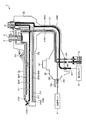
続いて、超音波内視鏡2に形成されている複数の管路6の構成について、図3を参照して説明する。図3は、超音波内視鏡2に設けられた複数の管路6を模式的に示す図である。
Next, the configuration of the plurality of
複数の管路6は、上述したように、先端側第1〜第5管路61〜65と、基端側第1〜第3管路66〜68とで構成されている。
As described above, the plurality of
先端側第1管路61は、処置具チャンネル2154から処置具(例えば、穿刺針等)を外部に突出させるための管路であるとともに、当該処置具チャンネル2154から被検体内の液体を吸引するための管路である。この先端側第1管路61は、図3に示すように、処置具チューブ611と、吸引チューブ612と、を備える。
The distal-side
処置具チューブ611は、湾曲部213及び可撓管部214の内部に引き回され、一端が処置具チャンネル2154に連通する。また、処置具チューブ611は、操作部22に設けられた処置具挿入口223に連通する。すなわち、処置具(例えば、穿刺針等)は、処置具挿入口223を介して、処置具チューブ611に挿入され、処置具チャンネル2154から外部に突出することとなる。
The
吸引チューブ612は、操作部22の内部に引き回され、一端が処置具チューブ611の他端に連通し、他端が吸引シリンダ8に連通する。
The
先端側第2管路62は、送気送水用孔2155から撮像用孔(図示略)に向けて送気するための管路であり、湾曲部213、可撓管部214、及び操作部22の内部に引き回され、一端が送気送水用孔2155に連通し、他端が送気送水シリンダ7に連通する。
The distal-end-side
先端側第3管路63は、送気送水用孔2155から撮像用孔(図示略)に向けて送水するための管路であり、湾曲部213、可撓管部214、及び操作部22の内部に引き回され、一端が送気送水用孔2155に連通し、他端が送気送水シリンダ7に連通する。
The distal-end-side
先端側第4管路64は、送水用孔217からバルーン(図示略)内に水を充填するための管路であり、湾曲部213、可撓管部214、及び操作部22の内部に引き回され、一端がバルーン注水口2163に連通し、他端が送気送水シリンダ7に連通する。
The distal-end-side
先端側第5管路65は、吸引用孔218からバルーン(図示略)内の水を吸引するための管路であり、湾曲部213、可撓管部214、及び操作部22の内部に引き回され、一端がバルーン吸引口2164に連通し、他端が吸引シリンダ8に連通する。
The distal-end-side
基端側第1管路66は、光源ポンプP1から吐出された空気を送気送水シリンダ7及び送水タンクTaに流通させる管路であり、操作部22、ユニバーサルケーブル23、及び内視鏡用コネクタ24の内部に引き回されている。そして、基端側第1管路66は、内視鏡用コネクタ24内で2つに分岐された各一端が送気用口金244及び加圧用口金245にそれぞれ連通し、他端が送気送水シリンダ7に連通する。
The proximal-side
基端側第2管路67は、送水タンクTaから吐出された水を送気送水シリンダ7に流通させる管路であり、操作部22、ユニバーサルケーブル23、及び内視鏡用コネクタ24の内部に引き回されている。そして、基端側第2管路67は、一端が送水用口金246に連通し、他端が送気送水シリンダ7に連通する。
The proximal-side
基端側第3管路68は、吸引シリンダ8内の液体を吸引するための管路であり、操作部22、ユニバーサルケーブル23、及び内視鏡用コネクタ24の内部に引き回され、一端が吸引用口金247に連通し、他端が吸引シリンダ8に連通する。
The proximal
次に、吸引シリンダ8の構成について、図6を参照して説明する。図6は、吸引シリンダの構成を示す断面図である。吸引シリンダ8は、図6中、上下方向に延びる中心軸Ax1を中心軸とする円筒状をなす。そして、吸引シリンダ8は、図6に示すように、中心軸Ax1に沿って、第1連通管路81と、第1連通管路81の外周を覆う筒部82と、中心軸Ax1に沿った方向において、中心軸Ax1から離間した位置に延在する第3連通管路83と、を備える。
Next, the configuration of the
第1連通管路81の上端部には、後述する吸引ボタン10の軸部103が摺動可能に勘合する内径を有する第1連通パイプ81aが第1連通管路81と同軸、かつ一体的に接続されている。第1連通パイプ81aには、筒部82と連通する連通孔811が形成されている。第1連通管路81の下端部には、図6に示すように、口金等を介して、先端側第1管路61の他端が接続されている。
At the upper end of the
筒部82の底面の一部には、図6に示すように、第2連通管路821が形成されており、第2連通管路821には、基端側第3管路68の他端が接続されている。筒部82の上端には、図6に示すように、吸引ボタン10を取り付けるための口金部84が固定されている。
As shown in FIG. 6, a
第3連通管路83は、上方から順に小径部831と、大径部832と、を有する。そして、第3連通管路83には、図6に示すように、口金等を介して、先端側第5管路65の他端が接続されている。
The
口金部84は、円筒形状を有し、例えば螺合により筒部82の外周面に固定される。そして、口金部84は、筒部82の外周面に固定された状態で、操作部22の内部から外部に突出する。口金部84の外周面には、図6に示すように、当該外周面の全周に亘って延在する円環形状を有し、当該外周面の上端から中心軸Ax1に離間する側に張り出した係合用突起部841が設けられている。
The
次に、吸引ボタン10の構成について、図7〜図9を参照して説明する。図7は、吸引ボタンを吸引シリンダに装着した状態を示す断面図である。具体的に、図7は、吸引ボタン10を口金部84(吸引シリンダ8)に装着した状態を示す断面図である。すなわち、図7中、下方側は、口金部84への吸引ボタン10の装着方向の先端側を示している。図8は、吸引ボタンの構成を示す斜視図である。図9は、吸引ボタンの斜視分解図である。
Next, the configuration of the
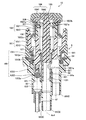
吸引ボタン10は、口金部84(吸引シリンダ8)に取り付けられる取付部101と、取付部101に移動可能に保持される可動ばね受部102と、可動ばね受部102に移動可能に保持される軸部103と、軸部103の一端に固定されているキャップ部104と、可動ばね受部102に固定されている可動ピストン部105と、可動ばね受部102とキャップ部104とを互いに離間する方向に付勢する第1コイルばね106と、取付部101と可動ばね受部102(可動ピストン部)とを互いに離間する方向に付勢する第2コイルばね107と、を備える。吸引ボタン10は、超音波内視鏡2に対して、着脱可能である。その結果、一度診断を行った後、再度診断を行う場合には、使用済みの吸引ボタン10を超音波内視鏡2から取り外して廃棄し、超音波内視鏡2に新しい吸引ボタン10を取る付けることにより、吸引ボタン10を洗浄する必要が生じない。換言すると、吸引ボタン10は、使い捨て可能(ディスポーザブル)とされている。
The
取付部101は、硬質な樹脂からなる筒状の取付部本体1011と、ゴム、シリコーン、又は熱可塑性エラストマー等の弾性を有する材料からなり、取付部本体1011の外周を覆う取付ゴム1012と、を有する。取付ゴム1012の一端には爪状の取付部固定部1012aが形成されている。そして、取付部固定部1012aが口金部84の係合用突起部841に嵌合することにより、取付部101が口金部84に固定される。さらに、取付ゴム1012の端部には、口金部84と当接して、取付ゴム1012と口金部84との間をシールするシール部1012bが形成されている。
The
可動ばね受部102は、取付部101の一部と第2コイルばね107とを挟んだ状態で、可動ピストン部105と超音波溶着により接合されている。可動ばね受部102は、硬質な樹脂からなる筒状の可動ばね受部本体1021と、ゴム、シリコーン、又は熱可塑性エラストマー等の弾性を有する材料からなり、可動ばね受部本体1021の外周を覆う可動ばね受部パッキン1022と、を有する。受部パッキン1022には、取付部本体1011と受部パッキン1022との間を摺動可能にシールするシール部1022aが形成されている。
The movable
軸部103は、図9に示すように、略棒状をなして延びている。また、軸部103には、中心軸Ax1方向に延びる中空空間を形成する孔部1031が形成されている。孔部1031は、図7に示すように、軸部103の中心軸Ax1の一端から延び、他端が軸部103内に位置している。孔部1031には、中心軸Ax1が通過している。また、軸部103には、中心軸Ax1と直交する方向の側面と、孔部1031との間を連通する連通孔1031aが形成されている。さらに、孔部1031の外周面には、第1連通パイプ81aの内周面と摺動可能に嵌合し、この嵌合により第1連通パイプ81aと孔部1031との間をシールするシール部1031bが形成されている。軸部103は、可動ばね受部102の一部と第1コイルばね106とを挟んだ状態で、キャップ部104と超音波溶着により接合されている。
As shown in FIG. 9, the
キャップ部104は、可動ばね受部102及び可動ピストン部105を移動させる操作を受け付ける。中空円板状の第1部材1041と、第1部材1041の内部に設けられる第2部材1042と、を有する。キャップ部104は、超音波溶着により軸部103と接合されている。
The
可動ピストン部105は、超音波内視鏡2の管路(第3連通管路83)に対して挿抜可能に移動可能である。可動ピストン部105は、管路(第3連通管路83)に対する挿抜に応じて、超音波内視鏡2の吸引系管路を切り換える。
The
可動ピストン部105は、可動ばね受部102に固定される可動ピストン部本体1051と、管路(第3連通管路83)に沿って延在するピストン部1052と、ピストン部1052の外周に配置されており、管路(第3連通管路83)内に挿通されたピストン部1052と管路(第3連通管路83)との隙間を埋めるパッキン部1053と、を有する。可動ピストン部本体1051及びピストン部1052は一体的に形成された硬質な樹脂からなる。ピストン部1052は、キャップ部104の中心とは異なる位置に延在している。パッキン部1053は、ゴム、シリコーン、又は熱可塑性エラストマー等の弾性を有する材料からなり、第3連通管路83の小径部831とパッキン部1053との間を摺動可能にシールするシール部1053aが形成されている。
The
第1コイルばね106は、線材を螺旋状に巻回してなる。第1コイルばね106は、可動ばね受部102とキャップ部104との間に設けられ、両者に対して互いに離れる方向の付勢力を付与する。この第1コイルばね106による付勢力は、軸部103と取付部101との突当面で受けている。
The
第2コイルばね107は、線材を螺旋状に巻回してなる。第2コイルばね107は、取付部101と可動ばね受部102との間に設けられ、両者に対して互いに離れる方向の付勢力を付与する。また、吸引ボタン10に操作が行われていない状態では、取付部101の一部が可動ピストン部105に当接しており、第1コイルばね106は、可動ばね受部102と可動ピストン部105とを互いに離間する方向に付勢する。この第2コイルばね107による付勢力は、取付部101と可動ピストン部105との突当面で受けている。第2コイルばね107の使用時力量は、第1コイルばね106の使用時最大力量よりも大きい。
The
吸引ボタン10は、キャップ部104に対する操作に応じて、軸部103が可動ばね受部102に対して移動することにより、超音波内視鏡2の第2連通管路821が第1連通管路81と連通する。吸引ボタン10は、キャップ部104に対する操作に応じて、可動ピストン部105が可動ばね受部102と一体的に取付部101に対して移動することにより、超音波内視鏡2の第3連通管路83が第2連通管路821と連通する。より詳細な吸引ボタン10の動作については後述する。
In the
次に、吸引ボタン10の組み立てについて説明する。取付部101の下方(図9の中心軸Ax1に沿って左側)から可動ピストン部105を嵌合する。この時、取付部101と可動ピストン部105とは、Ax1を回転軸として相対的に回転しないよう互いに固定される。続いて、取付部101の上方(図9の中心軸Ax1に沿って右側)から第2コイルばね107を挟むように可動ばね受部102を取り付ける。この際、可動ばね受部102と可動ピストン部105とを超音波溶着により固定する。
Next, assembly of the
その後、取付部101等と一体となった可動ピストン部105の下方から軸部103を挿入する。この時、取付部101と軸部103とは、Ax1を回転軸として相対的に回転しないよう互いに固定される。続いて、取付部101の上方から第1コイルばね106を挟むようにキャップ部104を取り付ける。この際、軸部103とキャップ部104とを超音波溶着により固定する。これにより、上述した吸引ボタン10を得る。
Thereafter, the
次に、送気送水ボタン9及び吸引ボタン10による複数の管路6の接続状態について、図7、図10〜図15を参照して説明する。以下では、無操作の場合、送気送水ボタン9のリーク孔91を指で塞いだ場合、一段、押込み操作した場合、二段、押込み操作した場合を順に説明する。
Next, a connection state of the plurality of
〔無操作の場合〕
図7及び図10は、送気送水ボタン及び吸引ボタンに対して、操作を行わない場合の複数の管路の接続状態を示す図である。
[No operation]
7 and 10 are diagrams illustrating a connection state of a plurality of pipelines when no operation is performed on the air / water supply button and the suction button.
送気送水ボタン9に対して無操作の場合には、光源ポンプP1から吐出された空気は、基端側第1管路66を介して、送気送水シリンダ7に向けて流通する。そして、送気送水シリンダ7に向けて流通した空気は、リーク孔91を通過し、超音波内視鏡2の外部に排出される。
When no operation is performed on the air /
また、吸引ボタン10に対して無操作の場合には、先端側第1管路61に対してはシール部1031bにより封止され、先端側第5管路65に対してはシール部1053aにより封止される。一方、外部の空気に対しては、シール部1012b及び1022aにおいては封止されているが、リーク孔1021aのみが開口している。このため、吸引ポンプP2の駆動に伴い、超音波内視鏡2の外部の空気は、吸引ボタン10におけるリーク孔1021aを介して、吸引シリンダ8内に流入し、基端側第3管路68を介して、吸引ポンプP2に吸引される。このとき、リーク孔1021aの開口面積は、基端側第3管路68の断面積以上であるため、吸引ポンプP2による吸引圧が先端側第1管路61及び先端側第5管路65に作用することが防止されている。
When the
すなわち、当該無操作の場合には、先端側第1〜第5管路61〜65と基端側第1〜第3管路66〜68とが接続されることがなく、挿入部21の先端から送気、送水、及び吸引のいずれも実行されない。
That is, in the case of no operation, the distal end side first to
〔リーク孔を指で塞いだ場合〕
図11は、送気送水ボタンのリーク孔を指で塞いだ場合の複数の管路の接続状態を示す図である。なお、図11では、吸引ボタン10には図10と同様に、何ら操作されていない。
[When the leak hole is blocked with a finger]
FIG. 11 is a diagram illustrating a connection state of a plurality of pipelines when a leak hole of the air / water supply button is blocked with a finger. In FIG. 11, the
リーク孔91を指で塞いだ場合には、送気送水シリンダ7に流入した空気は、先端側第2管路62に流通する。そして、先端側第2管路62に流通した空気は、図11に示すように、送気送水用孔2155から撮像用孔(図示略)内の対物光学系(図示略)に向けて吐出される。
When the
〔一段、押込み操作した場合〕
図12は、吸引ボタンに対して一段、押込み操作した状態を示す断面図である。図13は、送気送水ボタン及び吸引ボタンに対して一段、押込み操作した場合の複数の管路の接続状態を示す図である。
[In the case of a push-in operation]
FIG. 12 is a cross-sectional view showing a state in which the suction button has been pushed in one step. FIG. 13 is a diagram illustrating a connection state of a plurality of pipelines when a push operation is performed on the air / water supply button and the suction button.
送気送水ボタン9を一段、押込み操作した場合には、光源ポンプP1から吐出された空気は、図13に示すように、基端側第1管路66を介して、送水タンクTa内に流入し、当該送水タンクTa内を加圧し、当該送水タンクTaから水を流出させる。そして、送水タンクTaからの水は、基端側第2管路67を介して、送気送水シリンダ7に向けて流通する。送気送水シリンダ7に向けて流通した水は、先端側第3管路63に流通する。そして、先端側第3管路63に流通した水は、送気送水用孔2155から撮像用孔(図示略)内の対物光学系(図示略)に向けて吐出される。
When the air supply /
また、吸引ボタン10を一段、押込み操作した場合には、図12に示すように、キャップ部104と可動ばね受部102の可動ばね受部パッキン1022とが当接し、シール部1022bがリーク孔1021aを封止する。また、超音波溶着によりキャップ部104と一体となった軸部103も第1連通パイプ81a内を下方に摺動し、軸部103の連通孔1031aが第1連通パイプ81aの連通孔811と同軸状態となる。この際には、先端側第5管路65に対してはシール部1053aにより封止され、外部の空気に対しては、シール部1012b、1022a、及び1022bにより封止される。一方、軸部103の連通孔1031aと第1連通パイプ81aの連通孔811とが同軸(開口)となることにより、先端側第1管路61と基端側第3管路68とが接続(連通)される。そして、被検体内の液体は、処置具チャンネル2154から先端側第1管路61に流入し、吸引シリンダ8及び基端側第3管路68を介して、吸引ポンプP2に吸引される。なお、このように処置具チャンネル2154から被検体内の液体を吸引する場合には、処置具挿入口223を閉塞して吸引圧が先端側(処置具チャンネル2154側)に掛かるようにするために、当該処置具挿入口223に鉗子栓(図示略)が取り付けられる。
Further, when the
〔二段、押込み操作した場合〕
図14は、吸引ボタンに対して二段、押込み操作した状態を示す断面図である。図15は、送気送水ボタン及び吸引ボタンに対して二段、押込み操作した場合の複数の管路の接続状態を示す図である。
[In the case of two-stage push-in operation]
FIG. 14 is a cross-sectional view showing a state where the suction button has been pushed in two steps. FIG. 15 is a diagram illustrating a connection state of a plurality of pipelines when the air supply / water supply button and the suction button are pushed in two steps.
送気送水ボタン9を二段、押込み操作した場合(図13に示した状態からさらに一段、押込み操作した場合)には、送気送水シリンダ7に向けて流通した水は、先端側第4管路64に流通する。そして、先端側第4管路64に流通した水は、図15に示すように、送水用孔217、バルーン注水口2163を介して、バルーン(図示略)内に充填される。
When the air /
また、吸引ボタン10を二段、押込み操作した場合には、図14に示すように、シール部1022bによるキャップ部104と可動バネ受け部102との間のシール、及びシール部1022aによる可動バネ受け部102と取付部101との間のシールは維持したまま、軸部103と可動ピストン部105とがそれぞれ第1連通パイプ81a、第3連通管路83内を下方に移動し、軸部103は第1連通パイプ81aとの摺動嵌合により、シール部1031cが軸部103と第1連通パイプ81aとの間をシールするとともに、可動ピストン部105のパッキン部1053が第3連通管路83の小径部831から大径部832に位置する。この際には、先端側第1管路61に対してはシール部1031cにより封止され、外部の空気に対しては、シール部1012b、1022a、及び1022bにより封止される。一方、可動ピストン部105のパッキン部1053が第3連通管路83の大径部832に移動することにより、シール部1053aが開放され、先端側第5管路65と基端側第3管路68とが接続(連通)される。そして、被検体内の液体(例えば、バルーン内の水)は、バルーン吸引口2164から先端側第5管路65に流入し、吸引シリンダ8及び基端側第3管路68を介して、吸引ポンプP2に吸引される。
When the
次に、可動ばね受部102と可動ピストン部105との接合部について説明する。図16は、図7の領域Bの部分拡大図であり、(a)は溶着前、(b)は溶着後を示す。図15の(a)、(b)に示すように、可動ばね受部102の可動ばね受部本体1021は、円筒状のリブ1021bを有する。可動ピストン部105の可動ピストン部本体1051は、リブ1021bが挿入されるリブ受け溝1051aを有する。そして、可動ばね受部102と可動ピストン部105とは、超音波溶着により接合されている。その結果、リブ1021bの溶融部端1021cとリブ受け溝1051aの底面1051bの極表面部分とが接合され、溶着部(溶着面)10aが形成される。また、リブ1021bの側面とリブ受け溝1051aの側面との間には隙間が形成されており、この隙間の少なくとも一部にはリブ1021bの溶融樹脂1021dが流れ出し、樹脂10bとして充填され、可動ばね受部102と可動ピストン部105との接合部を接着剤のように補強している。この樹脂10bは、可動ピストン部105に対する可動ばね受部102の引張り方向の力に対してはせん断方向の力となるため、接着強度が強くなる。その結果、実施の形態によれば、樹脂からなる可動ばね受部102と可動ピストン部105とが剥離することを防止することができる。なお、リブ1021bの側面とリブ受け溝1051aの側面との間には、溶融した樹脂10bがこの隙間の体積の50%以上充填されていることが好ましい。隙間への樹脂の充填率が高いほど、可動ばね受部102と可動ピストン部105との接合が強固になるためである。
Next, a joint portion between the movable
また、上述した実施の形態に係る内視鏡用ディスポーザブル管路切換装置(吸引ボタン10)では、二段階の押込み操作により、複数の管路6の接続状態を切り替える構造を採用していたが、これに限らず、一段階の押込み操作のみ実行可能とする構造を採用してもよい。
Moreover, in the endoscope disposable pipe switching device (suction button 10) according to the above-described embodiment, a structure in which the connection state of the plurality of
また、上述した実施の形態では、内視鏡システム1は、超音波画像を生成する機能、及び内視鏡画像を生成する機能の双方を有するものとして説明したが、これに限らず、超音波画像を生成する機能のみを有する構成としてもよい。 In the above-described embodiment, the endoscope system 1 has been described as having both a function of generating an ultrasonic image and a function of generating an endoscopic image. It is good also as a structure which has only the function to produce | generate an image.
また、上述した実施の形態において、内視鏡システム1は、医療分野に限らず、工業分野において、機械構造物等の被検体の内部を観察する内視鏡システムとしてもよい。 In the above-described embodiment, the endoscope system 1 is not limited to the medical field, and may be an endoscope system that observes the inside of a subject such as a mechanical structure in the industrial field.
さらなる効果や変形例は、当業者によって容易に導き出すことができる。よって、本発明のより広範な態様は、以上のように表し、かつ記述した特定の詳細及び代表的な実施の形態に限定されるものではない。従って、添付のクレーム及びその均等物によって定義される総括的な発明の概念の精神又は範囲から逸脱することなく、様々な変更が可能である。 Further effects and modifications can be easily derived by those skilled in the art. Thus, the broader aspects of the present invention are not limited to the specific details and representative embodiments shown and described above. Accordingly, various modifications can be made without departing from the spirit or scope of the general inventive concept as defined by the appended claims and their equivalents.
1 内視鏡システム
2 超音波内視鏡
3 超音波観測装置
4 内視鏡観察装置
5 表示装置
6 複数の管路
7 送気送水シリンダ
8 吸引シリンダ
9 送気送水ボタン
10 吸引ボタン
10a 溶着部
10b 樹脂
21 挿入部
22 操作部
23 ユニバーサルケーブル
24 内視鏡用コネクタ
31 超音波ケーブル
42 光源装置
61〜65 先端側第1〜第5管路
66〜68 基端側第1〜第3管路
81 第1連通管路
81a 第1連通パイプ
82 筒部
83 第3連通管路
84 口金部
91、1021a リーク孔
103 軸部
104 キャップ部
101 取付部
102 可動ばね受部
105 可動ピストン部
106 第1コイルばね
107 第2コイルばね
211 超音波探触子
212 硬性部材
213 湾曲部
214 可撓管部
215、832 大径部
216、831 小径部
217 送水用孔
218 吸引用孔
221 湾曲ノブ
222 操作部材
223 処置具挿入口
241 超音波コネクタ
242 プラグ部
243 ライトガイド口金
244 送気用口金
245 加圧用口金
246 送水用口金
247 吸引用口金
611 処置具チューブ
612 吸引チューブ
811、1031a 連通孔
821 第2連通管路
841 係合用突起部
1041 第1部材
1042 第2部材
1011 取付部本体
1012 取付ゴム
1012a 取付部固定部
1012b、1022a、1022b、1031b、1031c、1053a シール部
1021 可動ばね受部本体
1021b リブ
1021c 溶融部端
1021d 溶融樹脂
1022 可動ばね受部パッキン
1031 孔部
1051 可動ピストン部本体
1051a リブ受け溝
1051b 底面
1052 ピストン部
1053 パッキン部
2111 振動子部
2111a 圧電素子
2111b 第1音響整合層
2111ba、2111ha 電極
2111c 第2音響整合層
2111d 音響レンズ
2111e バッキング材
2111f 構造部材
2111fa 第1構造部材
2111fb 第2構造部材
2111g 接合部
2111h 基板
2112 先端部
2151 テーパ面
2152 照明用孔
2153 撮像用孔
2154 処置具チャンネル
2155 送気送水用孔
2161、2162 バルーン取付溝
2163 バルーン注水口
2164 バルーン吸引口
DESCRIPTION OF SYMBOLS 1 Endoscope system 2 Ultrasound endoscope 3 Ultrasound observation apparatus 4 Endoscope observation apparatus 5 Display apparatus 6 Several pipe lines 7 Air supply / water supply cylinder 8 Suction cylinder 9 Air supply / water supply button 10 Suction button 10a Welding part 10b Resin 21 Insertion section 22 Operation section 23 Universal cable 24 Endoscope connector 31 Ultrasonic cable 42 Light source device 61-65 Tip side first to fifth pipes 66 to 68 Base end side first to third pipes 81 First 1 communicating pipe 81a 1st communicating pipe 82 cylinder part 83 3rd communicating pipe 84 cap part 91,1021a leak hole 103 shaft part 104 cap part 101 attaching part 102 movable spring receiving part 105 movable piston part 106 first coil spring 107 Second coil spring 211 Ultrasonic probe 212 Hard member 213 Curved portion 214 Flexible tube portion 215, 832 Large diameter portion 216 , 831 Small diameter part 217 Water supply hole 218 Suction hole 221 Bending knob 222 Operation member 223 Treatment instrument insertion port 241 Ultrasonic connector 242 Plug part 243 Light guide base 244 Air supply base 245 Pressure base 246 Water supply base 247 For suction Base 611 Treatment tool tube 612 Suction tube 811, 1031 a Communication hole 821 Second communication pipe 841 Engaging protrusion 1041 First member 1042 Second member 1011 Mounting portion main body 1012 Mounting rubber 1012a Mounting portion fixing portion 1012b, 1022a, 1022b 1031b, 1031c, 1053a Seal part 1021 Movable spring receiving part main body 1021b Rib 1021c Melting part end 1021d Molten resin 1022 Movable spring receiving part packing 1031 Hole part 1051 Movable piston part main body 1051a Receiving groove 1051b bottom surface 1052 piston part 1053 packing part 2111 transducer part 2111a piezoelectric element 2111b first acoustic matching layer 2111ba electrode 2111c second acoustic matching layer 2111d acoustic lens 2111e backing material 2111f structural member 2111fa first structural member 2111fb second Structural member 2111g Joint 2111h Substrate 2112 Tip 2151 Tapered surface 2152 Illumination hole 2153 Imaging hole 2154 Treatment instrument channel 2155 Air supply / water supply hole 2161, 2162 Balloon mounting groove 2163 Balloon injection port 2164 Balloon suction port
Claims (8)
前記取付部に移動可能に保持されており、円筒状のリブを有する樹脂からなる可動ばね受部と、
前記リブが挿入されるリブ受け溝を有し、内視鏡の管路に対して挿抜可能に移動可能な樹脂からなる可動ピストン部と、
を備え、
前記可動ばね受部と前記可動ピストン部とは、超音波溶着により接合されており、前記リブの先端と前記リブ受け溝の底面との間には溶着部が形成されており、前記リブの側面と前記リブ受け溝の側面との間には隙間が形成されており、該隙間の少なくとも一部には溶融した樹脂が充填されていることを特徴とする内視鏡用ディスポーザブル管路切換装置。 An attachment portion attached to the endoscope;
A movable spring receiving portion made of resin having a cylindrical rib, which is held movably in the mounting portion;
A movable piston portion made of a resin having a rib receiving groove into which the rib is inserted and movable so as to be inserted into and removed from an endoscope duct;
With
The movable spring receiving portion and the movable piston portion are joined by ultrasonic welding, and a welding portion is formed between the tip of the rib and the bottom surface of the rib receiving groove, and the side surface of the rib And a side surface of the rib receiving groove, and a gap is formed, and at least a part of the gap is filled with molten resin.
前記軸部の一端に固定されているキャップ部と、
前記可動ばね受部と前記キャップ部とを互いに離間する方向に付勢する第1コイルばねと、
を備えることを特徴とする請求項1〜4のいずれか1つに記載の内視鏡用ディスポーザブル管路切換装置。 A shaft portion movably held by the movable spring receiving portion;
A cap portion fixed to one end of the shaft portion;
A first coil spring that biases the movable spring receiving portion and the cap portion away from each other;
The disposable pipe switching device for an endoscope according to any one of claims 1 to 4, wherein:
前記キャップ部に対する操作に応じて、前記可動ピストン部が前記可動ばね受部と一体的に前記取付部に対して移動することにより、前記内視鏡の第2管路が連通することを特徴とする請求項5に記載の内視鏡用ディスポーザブル管路切換装置。 In response to an operation on the cap portion, the shaft portion moves with respect to the movable spring receiving portion, whereby the first conduit of the endoscope communicates,
In response to an operation on the cap portion, the movable piston portion moves integrally with the movable spring receiving portion with respect to the attachment portion, whereby the second conduit of the endoscope communicates. The disposable conduit switching device for an endoscope according to claim 5.
Priority Applications (3)
| Application Number | Priority Date | Filing Date | Title |
|---|---|---|---|
| JP2018097355A JP6998274B2 (en) | 2018-05-21 | 2018-05-21 | Pipeline switching device for endoscopes and endoscopes |
| PCT/JP2019/019985 WO2019225563A1 (en) | 2018-05-21 | 2019-05-20 | Disposable endoscope tube switching device |
| US17/094,123 US11805979B2 (en) | 2018-05-21 | 2020-11-10 | Endoscope conduit switching device and endoscope |
Applications Claiming Priority (1)
| Application Number | Priority Date | Filing Date | Title |
|---|---|---|---|
| JP2018097355A JP6998274B2 (en) | 2018-05-21 | 2018-05-21 | Pipeline switching device for endoscopes and endoscopes |
Publications (3)
| Publication Number | Publication Date |
|---|---|
| JP2019201732A true JP2019201732A (en) | 2019-11-28 |
| JP2019201732A5 JP2019201732A5 (en) | 2021-07-26 |
| JP6998274B2 JP6998274B2 (en) | 2022-01-18 |
Family
ID=68615810
Family Applications (1)
| Application Number | Title | Priority Date | Filing Date |
|---|---|---|---|
| JP2018097355A Active JP6998274B2 (en) | 2018-05-21 | 2018-05-21 | Pipeline switching device for endoscopes and endoscopes |
Country Status (3)
| Country | Link |
|---|---|
| US (1) | US11805979B2 (en) |
| JP (1) | JP6998274B2 (en) |
| WO (1) | WO2019225563A1 (en) |
Cited By (2)
| Publication number | Priority date | Publication date | Assignee | Title |
|---|---|---|---|---|
| KR20230072521A (en) * | 2021-11-15 | 2023-05-25 | 주식회사 로엔서지컬 | Endoscopic apparatus |
| CN116746858A (en) * | 2023-06-30 | 2023-09-15 | 北理工郑州智能科技研究院 | 3D imaging endoscope capable of being used for high-temperature high-pressure repeated elimination |
Families Citing this family (1)
| Publication number | Priority date | Publication date | Assignee | Title |
|---|---|---|---|---|
| CN120643166A (en) * | 2025-06-30 | 2025-09-16 | 杭州鑫泽源医疗科技有限公司 | Accessory for endoscope and ultrasonic endoscope |
Citations (4)
| Publication number | Priority date | Publication date | Assignee | Title |
|---|---|---|---|---|
| JP2009085301A (en) * | 2007-09-28 | 2009-04-23 | Fuji Koki Corp | Synthetic resin housing for valve apparatus |
| WO2017091459A1 (en) * | 2015-11-24 | 2017-06-01 | Endochoice, Inc. | Disposable air/water and suction valves for an endoscope |
| WO2017149828A1 (en) * | 2016-02-29 | 2017-09-08 | オリンパス株式会社 | Conduit control apparatus |
| WO2018003185A1 (en) * | 2016-06-29 | 2018-01-04 | オリンパス株式会社 | Endoscope button |
Family Cites Families (7)
| Publication number | Priority date | Publication date | Assignee | Title |
|---|---|---|---|---|
| JP2007111266A (en) | 2005-10-20 | 2007-05-10 | Olympus Medical Systems Corp | Endoscope switching device |
| WO2009001429A1 (en) * | 2007-06-25 | 2008-12-31 | Olympus Medical Systems Corp. | Medical equipment, medical device and endoscope |
| JP5250601B2 (en) * | 2010-10-12 | 2013-07-31 | 富士フイルム株式会社 | Endoscope switching device |
| JP5866329B2 (en) * | 2013-11-28 | 2016-02-17 | 富士フイルム株式会社 | Endoscope duct switching device and endoscope |
| JP5970008B2 (en) * | 2014-02-06 | 2016-08-17 | 富士フイルム株式会社 | Endoscope suction line switching device and endoscope |
| JP2018121922A (en) * | 2017-02-01 | 2018-08-09 | オリンパス株式会社 | Endoscope air supply/water supply valve and endoscope |
| JP2018121923A (en) * | 2017-02-01 | 2018-08-09 | オリンパス株式会社 | Air/water supply valve for endoscope and endoscope |
-
2018
- 2018-05-21 JP JP2018097355A patent/JP6998274B2/en active Active
-
2019
- 2019-05-20 WO PCT/JP2019/019985 patent/WO2019225563A1/en not_active Ceased
-
2020
- 2020-11-10 US US17/094,123 patent/US11805979B2/en active Active
Patent Citations (4)
| Publication number | Priority date | Publication date | Assignee | Title |
|---|---|---|---|---|
| JP2009085301A (en) * | 2007-09-28 | 2009-04-23 | Fuji Koki Corp | Synthetic resin housing for valve apparatus |
| WO2017091459A1 (en) * | 2015-11-24 | 2017-06-01 | Endochoice, Inc. | Disposable air/water and suction valves for an endoscope |
| WO2017149828A1 (en) * | 2016-02-29 | 2017-09-08 | オリンパス株式会社 | Conduit control apparatus |
| WO2018003185A1 (en) * | 2016-06-29 | 2018-01-04 | オリンパス株式会社 | Endoscope button |
Cited By (4)
| Publication number | Priority date | Publication date | Assignee | Title |
|---|---|---|---|---|
| KR20230072521A (en) * | 2021-11-15 | 2023-05-25 | 주식회사 로엔서지컬 | Endoscopic apparatus |
| KR102651160B1 (en) | 2021-11-15 | 2024-03-28 | 주식회사 로엔서지컬 | Endoscopic apparatus |
| CN116746858A (en) * | 2023-06-30 | 2023-09-15 | 北理工郑州智能科技研究院 | 3D imaging endoscope capable of being used for high-temperature high-pressure repeated elimination |
| CN116746858B (en) * | 2023-06-30 | 2024-05-10 | 北理工郑州智能科技研究院 | 3D imaging endoscope capable of being used for high-temperature high-pressure repeated elimination |
Also Published As
| Publication number | Publication date |
|---|---|
| US20210068780A1 (en) | 2021-03-11 |
| JP6998274B2 (en) | 2022-01-18 |
| US11805979B2 (en) | 2023-11-07 |
| WO2019225563A1 (en) | 2019-11-28 |
Similar Documents
| Publication | Publication Date | Title |
|---|---|---|
| US11241142B2 (en) | Endoscope valve and endoscope | |
| US20260041314A1 (en) | Endoscope conduit switching device and endoscope | |
| US11344187B2 (en) | Endoscope valve having deformable check valve on outer surface of valve main body and endoscope | |
| CN111789637B (en) | Ultrasound endoscope | |
| US11369256B2 (en) | Endoscope valve and endoscope | |
| US11389053B2 (en) | Endoscope valve and endoscope | |
| US11805979B2 (en) | Endoscope conduit switching device and endoscope | |
| JPWO2018003242A1 (en) | Ultrasound endoscope | |
| US12121208B2 (en) | Endoscope conduit switching device, endoscope, and method of manufacturing endoscope conduit switching device | |
| US10987087B2 (en) | Ultrasound endoscope | |
| WO2021193404A1 (en) | Ultrasonic endoscope | |
| JP6944885B2 (en) | Ultrasonic transducer and ultrasonic endoscope | |
| JP2012245061A (en) | Ultrasonic endoscope | |
| CN111656799B (en) | Ultrasound probe | |
| US20240215947A1 (en) | Ultrasonic endoscope system and method of operating ultrasonic endoscope system |
Legal Events
| Date | Code | Title | Description |
|---|---|---|---|
| A521 | Request for written amendment filed |
Free format text: JAPANESE INTERMEDIATE CODE: A523 Effective date: 20210519 |
|
| A621 | Written request for application examination |
Free format text: JAPANESE INTERMEDIATE CODE: A621 Effective date: 20210519 |
|
| A131 | Notification of reasons for refusal |
Free format text: JAPANESE INTERMEDIATE CODE: A131 Effective date: 20210928 |
|
| A521 | Request for written amendment filed |
Free format text: JAPANESE INTERMEDIATE CODE: A523 Effective date: 20211118 |
|
| TRDD | Decision of grant or rejection written | ||
| A01 | Written decision to grant a patent or to grant a registration (utility model) |
Free format text: JAPANESE INTERMEDIATE CODE: A01 Effective date: 20211207 |
|
| A61 | First payment of annual fees (during grant procedure) |
Free format text: JAPANESE INTERMEDIATE CODE: A61 Effective date: 20211220 |
|
| R151 | Written notification of patent or utility model registration |
Ref document number: 6998274 Country of ref document: JP Free format text: JAPANESE INTERMEDIATE CODE: R151 |
|
| R250 | Receipt of annual fees |
Free format text: JAPANESE INTERMEDIATE CODE: R250 |
|
| R250 | Receipt of annual fees |
Free format text: JAPANESE INTERMEDIATE CODE: R250 |