JP2019206149A - Thermal transfer sheet, and thermal transfer printing apparatus - Google Patents
Thermal transfer sheet, and thermal transfer printing apparatus Download PDFInfo
- Publication number
- JP2019206149A JP2019206149A JP2018103717A JP2018103717A JP2019206149A JP 2019206149 A JP2019206149 A JP 2019206149A JP 2018103717 A JP2018103717 A JP 2018103717A JP 2018103717 A JP2018103717 A JP 2018103717A JP 2019206149 A JP2019206149 A JP 2019206149A
- Authority
- JP
- Japan
- Prior art keywords
- layer
- thermal transfer
- transfer sheet
- base film
- identification mark
- Prior art date
- Legal status (The legal status is an assumption and is not a legal conclusion. Google has not performed a legal analysis and makes no representation as to the accuracy of the status listed.)
- Granted
Links
Images



Landscapes
- Electronic Switches (AREA)
- Thermal Transfer Or Thermal Recording In General (AREA)
Abstract
【課題】ICタグを使用せずに熱転写印画装置で熱転写シートの品種を識別する。【解決手段】熱転写シートは、基材フィルムの一方の面に、被転写体に転写される転写層が形成されている。この熱転写シートでは、前記転写層が形成される領域における前記基材フィルムの他方の面側、又は前記基材フィルムの一方の面と前記転写層との間に、前記熱転写シートの品種を識別するための識別マークが設けられている。転写層が被転写体に転写される際、前記識別マークは転写されずに熱転写シートに残存する。前記識別マークは、バーコード又は二次元コードである。【選択図】図1PROBLEM TO BE SOLVED: To identify the type of thermal transfer sheet by a thermal transfer printing apparatus without using an IC tag. SOLUTION: A thermal transfer sheet has a transfer layer formed on one surface of a base film and transferred to a transfer target. In this thermal transfer sheet, the type of the thermal transfer sheet is identified on the other surface side of the base film in the area where the transfer layer is formed, or between the one surface of the base film and the transfer layer. An identification mark for this is provided. When the transfer layer is transferred to the transfer target, the identification mark remains on the thermal transfer sheet without being transferred. The identification mark is a bar code or a two-dimensional code. [Selection diagram] Figure 1
Description
本発明は、熱転写シート及び熱転写印画装置に関する。 The present invention relates to a thermal transfer sheet and a thermal transfer printing apparatus.
熱転写印画装置にあっては、昇華転写用染料を記録材とし、これをポリエステルフィルム等の基材上に適当なバインダーで担持させた染料層を有する熱転写シート(昇華型熱転写シート)から、紙やプラスチックフィルム等に染料受容層を形成した受像シート上に昇華染料を熱転写し、各種のフルカラー画像を形成する。 In a thermal transfer printing apparatus, a dye for sublimation transfer is used as a recording material, and a thermal transfer sheet (sublimation type thermal transfer sheet) having a dye layer carried on a base material such as a polyester film with a suitable binder is used for paper or paper. A sublimation dye is thermally transferred onto an image receiving sheet having a dye receiving layer formed on a plastic film or the like to form various full color images.
近年、熱転写記録技術の進歩により、熱転写シートは、その種類が多岐にわたるようになっており、これらの多種類の熱転写シートを一機種の熱転写印画装置で使用する場合が増えている。所望の印画性能や耐久性を得るために、熱転写シートの品種を識別し、品種に応じて熱転写シートの加熱エネルギーを制御する必要がある。 In recent years, due to advances in thermal transfer recording technology, there are a wide variety of thermal transfer sheets, and the use of these various types of thermal transfer sheets in one type of thermal transfer printing apparatus is increasing. In order to obtain desired printing performance and durability, it is necessary to identify the type of thermal transfer sheet and control the heating energy of the thermal transfer sheet according to the type.
特許文献1には、熱転写シートを巻き付けた巻芯の端面のICタグホルダに、熱転写シートに関する固有情報を記憶したICタグを埋設する構成が開示されている。特許文献2には、巻芯の端部にアダプタを取り付け、アダプタの外周面にバーコードやICタグを取り付ける構成が開示されている。しかし、ICタグホルダやアダプタ等の部品を準備し、巻芯に組み付ける作業が必要であった。また、ICタグは高価であり、コストがかかっていた。
本発明は、上記従来の実状に鑑みてなされたものであり、熱転写印画装置で品種(製品種類、製品型番等)を識別可能とする熱転写シートを提供することを課題とする。また、本発明は、装填された熱転写シートを識別して印画処理を行う熱転写印画装置を提供することを課題とする。 The present invention has been made in view of the above-described conventional situation, and an object of the present invention is to provide a thermal transfer sheet that can identify a product type (product type, product model number, etc.) with a thermal transfer printing apparatus. Another object of the present invention is to provide a thermal transfer printing apparatus that performs printing processing by identifying a loaded thermal transfer sheet.
本発明の熱転写シートは、基材フィルムの一方の面に、被転写体に転写される転写層が形成されている熱転写シートであって、前記転写層が形成される領域における前記基材フィルムの他方の面側、又は前記基材フィルムの一方の面と前記転写層との間に、前記熱転写シートの品種を識別するための識別マークが設けられているものである。 The thermal transfer sheet of the present invention is a thermal transfer sheet in which a transfer layer to be transferred to a transfer medium is formed on one surface of the base film, and the base film in the region where the transfer layer is formed. An identification mark for identifying the type of the thermal transfer sheet is provided on the other surface side or between one surface of the base film and the transfer layer.
本発明の一態様では、前記基材フィルムの一方の面と前記転写層との間に離型層が設けられており、前記識別マークは、前記基材フィルムと前記離型層との間に設けられている。 In one aspect of the present invention, a release layer is provided between one surface of the base film and the transfer layer, and the identification mark is between the base film and the release layer. Is provided.
本発明の一態様では、前記識別マークは、前記離型層に含まれる樹脂と同じ樹脂を含む。 In one aspect of the present invention, the identification mark includes the same resin as the resin included in the release layer.
本発明の一態様では、前記基材フィルムの他方の面には、背面プライマー層を介して背面層が設けられており、前記識別マークは、前記基材フィルムと前記背面プライマー層との間に設けられている。 In one aspect of the present invention, a back layer is provided on the other surface of the base film via a back primer layer, and the identification mark is between the base film and the back primer layer. Is provided.
本発明の一態様では、前記識別マークは、前記背面プライマー層に含まれる樹脂と同じ樹脂を含む。 In one aspect of the present invention, the identification mark includes the same resin as that contained in the back primer layer.
本発明の一態様では、前記基材フィルムの他方の面には、背面プライマー層を介して背面層が設けられており、前記識別マークは、前記背面プライマー層と前記背面層との間に設けられている。 In one aspect of the present invention, a back surface layer is provided on the other surface of the base film via a back surface primer layer, and the identification mark is provided between the back surface primer layer and the back surface layer. It has been.
本発明の一態様では、前記識別マークは、前記背面層に含まれる樹脂と同じ樹脂を含む。 In one aspect of the present invention, the identification mark includes the same resin as the resin included in the back layer.
本発明の一態様では、前記転写層は、保護層、又は熱溶融インキ層を含む熱溶融転写層である。 In one aspect of the present invention, the transfer layer is a heat-melt transfer layer including a protective layer or a heat-melt ink layer.
本発明の一態様では、前記識別マークは、バーコード又は二次元コードである。 In one aspect of the present invention, the identification mark is a bar code or a two-dimensional code.
本発明の一態様では、前記識別マークは、不可視光線吸収材料を含む。 In one aspect of the present invention, the identification mark includes an invisible light absorbing material.
本発明の一態様では、前記転写層は保護層であり、前記基材フィルムの一方の面に、染料層と前記保護層とが面順次に形成されている。 In one embodiment of the present invention, the transfer layer is a protective layer, and the dye layer and the protective layer are formed in the surface order on one surface of the base film.
本発明の熱転写印画装置は、サーマルヘッド及びプラテンロールを有し、本発明の熱転写シートと、受像シートとを重ね合わせて、前記サーマルヘッドと前記プラテンロールとの間を搬送させるとともに、前記サーマルヘッドが前記熱転写シートを加熱して染料を転写して画像を形成し、前記画像上に前記保護層を転写する熱転写印画装置であって、前記熱転写シートから前記識別マークを読み取るセンサと、前記センサの読み取り結果から前記熱転写シートの品種を識別する識別部と、を備えるものである。 The thermal transfer printing apparatus of the present invention includes a thermal head and a platen roll, and the thermal transfer sheet of the present invention and an image receiving sheet are superposed to convey between the thermal head and the platen roll, and the thermal head Is a thermal transfer printing apparatus that heats the thermal transfer sheet to transfer a dye to form an image, and transfers the protective layer onto the image, a sensor that reads the identification mark from the thermal transfer sheet, and And an identification unit for identifying the type of the thermal transfer sheet from the read result.
本発明の一態様では、前記識別部が識別した前記熱転写シートの品種に応じた印画条件で印画処理を行う。 In one aspect of the present invention, the printing process is performed under printing conditions corresponding to the type of the thermal transfer sheet identified by the identification unit.
本発明の一態様では、前記センサは、前記サーマルヘッドと前記熱転写シートの供給部との間に設けられている。 In one aspect of the present invention, the sensor is provided between the thermal head and the supply portion of the thermal transfer sheet.
本発明によれば、熱転写印画装置で熱転写シートの品種(製品種類、製品型番等)を識別できる。 According to the present invention, the type (product type, product model number, etc.) of the thermal transfer sheet can be identified by the thermal transfer printing apparatus.
以下、図面を参照して実施の形態について説明する。図1は実施の形態に係る熱転写シート10の平面図であり、図2は図1のII-II線断面図、図3は図1のIII-III線断面図である。この熱転写シート10では、基材フィルム1の一方の面上に、イエロー染料層2Y、マゼンタ染料層2M、シアン染料層2Cの3色の染料層2と、熱転写性保護層3(以下、保護層3と記載する)とが面順次に繰り返し設けられている。
Hereinafter, embodiments will be described with reference to the drawings. 1 is a plan view of a
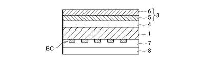
基材フィルム1の他方の面には、背面層8が設けられている。基材フィルム1と背面層8との密着性を良好にする目的で、基材フィルム1と背面層8との間に背面プライマー層7を設けてもよい。
A
保護層3は、剥離層5、及び剥離層5上に積層された接着層6を有する。基材フィルム1と保護層3との間、具体的には基材フィルム1と剥離層5との間に離型層4が設けられている。保護層3は、後述する受像シート22(図6参照)に形成された画像上に転写される層である。離型層4は受像シート22には転写されず、基材フィルム1上に残存する。
The
図1に示すように、保護層3が形成された保護層形成領域には、バーコードBCが設けられている。バーコードBCは、熱転写シート10の品種(製品種類、製品型番等)に対応する情報を示す。バーコードBCは、保護層形成領域のうち、受像シート22に転写されない位置に設けられる。
As shown in FIG. 1, a barcode BC is provided in the protective layer forming region where the
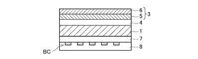
例えば、図3に示すように、バーコードBCは、基材フィルム1と離型層4との間に設けられる。図4に示すように、基材フィルム1と背面プライマー層7との間にバーコードBCを設けてもよい。あるいはまた、図5に示すように、背面プライマー層7と背面層8との間にバーコードBCを設けてもよい。
For example, as shown in FIG. 3, the barcode BC is provided between the
図6は、本発明の実施の形態に係る熱転写印画装置の概略構成図である。熱転写印画装置は、熱転写シート10を用いて、受像シート22上にイエロー染料、マゼンタ染料、シアン染料を昇華転写させて画像を印画し、画像上に保護層を形成するサーマルヘッド101を備えている。
FIG. 6 is a schematic configuration diagram of the thermal transfer printing apparatus according to the embodiment of the present invention. The thermal transfer printing apparatus includes a
サーマルヘッド101の下流側に、熱転写シート10を巻き付けて形成された供給部103が設けられ、サーマルヘッド101の上流側に回収部104が設けられている。供給部103から繰り出された熱転写シート10は、サーマルヘッド101を通って、回収部104に回収されるようになっている。
A
熱転写シート10及び受像シート22からみてサーマルヘッド101とは反対側の位置に、回転自在なプラテンロール102が設けられている。サーマルヘッド101及びプラテンロール102を含む印画部140は、熱転写シート10及び受像シート22を挟み込み、熱転写シート10の染料層2を加熱して、受像シート22上に染料を熱転写することで画像を形成する。
A
また、印画部140は、熱転写シート10の保護層形成領域を加熱して、受像シート22の画像上に保護層3を転写する。
In addition, the
サーマルヘッド101の上流側には、受像シート22の搬送を行うための回転駆動自在なキャプスタンローラ109aと、キャプスタンローラ109aに受像シート22を圧着させるためのピンチローラ109bが設けられている。
On the upstream side of the
受像シート22は、受像シートロール20から繰り出される。受像シート22には公知のものを使用できる。
The
印画部140で画像形成及び保護層の転写が施された受像シート22は、下流側でカッター108によりプリント枚葉Pとして切り出される。プリント枚葉Pは、図示を省略する排出口から排出される。
The
供給部103とサーマルヘッド101との間に、熱転写シート10の保護層形成領域に設けられたバーコードBCを読み取るセンサ120が設けられている。
Between the
制御装置110は、熱転写印画装置の各部の駆動を制御し、熱転写シート10の識別処理や、印画処理を行う。制御装置110は、CPU(中央演算処理装置)や、フラッシュメモリ、ROM(Read−only Memory)、RAM(Random Access Memory)等からなる記憶部112を有したコンピュータである。記憶部112は、制御プログラム及びテーブルTを格納する。CPUが制御プログラムを実行することで、識別部111での熱転写シート10の品種識別が実現される。
The
テーブルTには、バーコードBCから読み取られる情報と、熱転写シート10の品種とが対応付けて記録されている。テーブルTに、熱転写シート10の品種毎に好適な印画条件(印画速度、印画時の印加エネルギー)が記録されていてもよい。
In the table T, information read from the barcode BC and the type of the
識別部111は、テーブルTを参照し、センサ120の読み取り結果から、熱転写印画装置に装填されている熱転写シート10の品種を識別する。
The
制御装置110は、識別した熱転写シート10の品種に応じた印画条件に基づいて、印画処理を制御する。制御装置110は、センサ120の読み取り結果から熱転写シート10の品種が識別できない場合や、保護層形成領域にバーコードが設けられておらず、センサ120が情報を読み取れない場合に、警告音や警告表示を出力したり、印画処理を中止したりしてもよい。
The
このように、熱転写シート10の保護層形成領域に設けたバーコードBCを読み取ることで、熱転写シート10の品種を識別できる。バーコードBCは、保護層3を受像シート22に転写した後も熱転写シート10側に残存するため、プリント枚葉PにバーコードBCが形成されることはない。バーコードBCを、被転写体(受像シート22)に転写される転写層(剥離層5及び接着層6を有する保護層3)内に設けた場合、バーコードBCを不可視材料で形成していても、印画物(プリント枚葉P)に意図せぬ不具合が生じる可能性がある。そのため、バーコードBCは、保護層3を受像シート22に転写した後も熱転写シート10側に残存する位置に設けることが好ましい。
In this way, the type of the
センサ120はサーマルヘッド101と回収部104との間に設置してもよいが、印画処理における加熱により熱転写シート10に皺が生じてバーコードBCが読み取り難くなる可能性がある。供給部103とサーマルヘッド101との間にセンサ120を設け、印画処理前の熱転写シート10からバーコードBCを読み取ることが好ましい。
Although the
センサ120をサーマルヘッド101と回収部104との間に設置する場合は、バーコードBCを熱転写シート10の短手方向の中央部に設け、加熱に伴う皺がバーコードBCに重ならないようにすることが好ましい。
When the
本実施形態では、保護層形成領域にバーコードBCを設けているため、例えば染料層2同士の間の領域や、染料層2と保護層3との間の領域にバーコードBCを設ける場合と比較して、染料層2及び保護層3を基材フィルム1上に効率良く配置できる。
In this embodiment, since the barcode BC is provided in the protective layer forming region, for example, the barcode BC is provided in the region between the dye layers 2 or the region between the
バーコードでなく、二次元コードを設けてもよい。保護層形成領域を情報コード形成領域として使用できるため、二次元コードのようなサイズが大きい情報コードを容易に設けることができる。熱転写シート10の保護層形成領域に設ける、熱転写シート10の品種を識別するための識別マークは、バーコードや二次元コード等の情報コードに限定されず、英数字等の文字や図形であってもよい。
A two-dimensional code may be provided instead of the bar code. Since the protective layer forming region can be used as the information code forming region, an information code having a large size such as a two-dimensional code can be easily provided. An identification mark for identifying the type of the
バーコードBCとサーマルヘッド101との間には少なくとも背面層8が介在しているため、バーコードBCを形成するインキがサーマルヘッド101に付着して印画性能に影響を与えることを防止できる。図5に示す構成と比較して、図3や図4に示す構成ではバーコードBCとサーマルヘッド101との間にさらに多くの層が介在するため、サーマルヘッド101へのインキ付着防止効果がさらに向上される。
Since at least the
染料層2が形成された領域にバーコードBCが重なると印画ムラが生じ得るため、バーコードBCは保護層形成領域内に収まるように設けることが好ましい。図4や図5に示す構成では、フィルム基材1からみて、バーコードBCと保護層3とが異なる面に設けられているため、フィルム基材1の表面と裏面とで塗工位置を合わせる必要がある。一方、図3に示す構成では、バーコードBCと保護層3とがフィルム基材1の同じ面側に設けられているため、熱転写シート10の製造がより簡易となる。
If the barcode BC overlaps the region where the
バーコードBCを設けることで、層間の密着力が低下し得る。層間の密着性を考慮すると、バーコードBCは、熱源となるサーマルヘッド101から離れた位置にあることが好ましいため、図4や図5に示す構成よりも図3に示す構成の方が好ましい。
By providing the barcode BC, the adhesion between the layers can be reduced. Considering the adhesion between the layers, the barcode BC is preferably located at a position away from the
次に、熱転写シート10を構成する材料について説明する。
Next, materials constituting the
<基材フィルム>
熱転写シート10の基材フィルム1としては、従来公知のある程度の耐熱性と強度を有するものであればいずれのものでも良く、例えば、0.5μm以上50μm以下好ましくは3μm以上10μm以下程度の厚さのポリエチレンテレフタレートフィルム、1,4−ポリシクロヘキシレンジメチレンテレフタレートフィルム、ポリエチレンナフタレートフィルム、ポリフェニレンサルファイドフィルム、ポリスチレンフィルム、ポリプロピレンフィルム、ポリサルホンフィルム、アラミドフィルム、ポリカーボネートフィルム、ポリビニルアルコールフィルム、セロハン、酢酸セルロース等のセルロース誘導体、ポリエチレンフィルム、ポリ塩化ビニルフィルム、ナイロンフィルム、ポリイミドフィルム、アイオノマーフィルム等の樹脂フィルムの他に、コンデンサー紙、パラフィン紙等の紙類や不織布等、又は紙や不織布と樹脂との複合体であってもよい。
<Base film>
The
<染料層>
染料層2は、昇華性染料を含む層として形成する。
<Dye layer>
The
染料としては、公知の熱転写シートに使用されている染料は、いずれも本発明に使用可能であり、特に限定されない。これらの染料としてはジアリールメタン系、トリアリールメタン系、チアゾール系、メロシアニン等のメチン系、インドアニリン系、アセトフェノンアゾメチン,ピラゾロアゾメチン,イミダゾルアゾメチン,ピリドンアゾメチン等のアゾメチン系、キサンテン系、オキサジン系、ジシアノスチレン,トリシアノスチレンに代表されるシアノメチレン系、チアジン系、アジン系、アクリジン系、ベンゼンアゾ系、ピリドンアゾ,チオフェンアゾ,イソチアゾールアゾ,ピロールアゾ,ピラゾールアゾ,イミダゾールアゾ,チアジアゾールアゾ,トリアゾールアゾ,ジスアゾ等のアゾ系、スピロピラン系、インドリノスピロピラン系、フルオラン系、ローダミンラクタム系、ナフトキノン系、アントラキノン系、キノフタロン系等があげられる。 As the dye, any of the dyes used in known thermal transfer sheets can be used in the present invention and is not particularly limited. These dyes include diarylmethane, triarylmethane, thiazole, merocyanine and other methine, indoaniline, acetophenone azomethine, pyrazoloazomethine, azomethine such as imidazole azomethine, pyridone azomethine, xanthene, oxazine Cyanomethylene, thiazine, azine, acridine, benzeneazo, pyridoneazo, thiophenazo, isothiazole azo, pyrrole azo, pyrazole azo, imidazole azo, thiadiazole azo, triazole azo, represented by dicyanostyrene and tricyanostyrene Examples include azo compounds such as disazo, spiropyran compounds, indolinospiropyran compounds, fluoran compounds, rhodamine lactam compounds, naphthoquinone compounds, anthraquinone compounds, and quinophthalone compounds.
染料層は、基材フィルムの一方の面に、これらの染料及びバインダー樹脂、必要に応じて顔料、導電剤の少なくとも1つを添加して、トルエン、メチルエチルケトン、エタノール、イソプロピルアルコール、シクロヘキサノン、DMF等の適当な有機溶剤に溶解したり、あるいは有機溶剤や水等に分散させたりして、例えば、グラビア印刷法、スクリーン印刷法、リバースロールコーティング印刷法等の手段により塗布および乾燥することにより形成できる。染料層の厚みは、乾燥後の厚みで0.2μm以上6.0μm以下、好ましくは0.2μm以上3.0μm以下程度である。 The dye layer is formed by adding at least one of these dyes and a binder resin, if necessary, a pigment and a conductive agent to one surface of the base film, toluene, methyl ethyl ketone, ethanol, isopropyl alcohol, cyclohexanone, DMF, etc. For example, it can be dissolved in an appropriate organic solvent or dispersed in an organic solvent or water, and applied and dried by means of, for example, a gravure printing method, a screen printing method, or a reverse roll coating printing method. . The thickness of the dye layer is 0.2 μm or more and 6.0 μm or less, preferably 0.2 μm or more and 3.0 μm or less in terms of the thickness after drying.
<背面層>
背面層8は、基材フィルム1の保護層3が設けられた面とは反対側の面(裏面)に設けられ、サーマルヘッド等の加熱デバイスと基材フィルムとの熱融着を防止し、走行を滑らかにする。
<Back layer>
The
背面層を形成する樹脂としては、例えば、ポリビニルブチラール、ポリビニルアセトアセタール、ポリエステル、塩化ビニル−酢酸ビニル共重合体、ポリエーテル、ポリブタジエン、スチレン−ブタジエン共重合体、アクリルポリオール、ポリウレタンアクリレート、ポリエステルアクリレート、ポリエーテルアクリレート、エポキシアクリレート、ウレタン又はエポキシのプレポリマー、ニトロセルロース樹脂、セルロースナイトレート樹脂、セルロースアセトプロピオネート樹脂、セルロースアセテートブチレート樹脂、セルロースアセテートヒドロジエンフタレート樹脂、酢酸セルロース樹脂、ポリアミド、ポリイミド、ポリアミドイミド、ポリカーボネート、塩素化ポリオレフィン等が挙げられる。 Examples of the resin that forms the back layer include polyvinyl butyral, polyvinyl acetoacetal, polyester, vinyl chloride-vinyl acetate copolymer, polyether, polybutadiene, styrene-butadiene copolymer, acrylic polyol, polyurethane acrylate, polyester acrylate, Polyether acrylate, epoxy acrylate, urethane or epoxy prepolymer, nitrocellulose resin, cellulose nitrate resin, cellulose acetopropionate resin, cellulose acetate butyrate resin, cellulose acetate hydrodiene phthalate resin, cellulose acetate resin, polyamide, polyimide , Polyamideimide, polycarbonate, chlorinated polyolefin and the like.
これらの樹脂から形成される背面層は、滑り性付与剤、充填剤(タルクなど)を添加して、熱転写シートの転写面と、熱転写シートの背面(背面層)との滑り性を良好にすることにより、巻き上げ時にシワ等が生じて、巻き太りが生じることを防止する機能が発揮できるので、好ましく行なわれる。背面層に添加、あるいは上塗りする滑り性付与剤としては、燐酸エステル、シリコーンオイル、グラファイトパウダー、シリコーン系グラフトポリマー、フッ素系グラフトポリマー、アクリルシリコーングラフトポリマー、アクリルシロキサン、アリールシロキサンなどのシリコーン重合体が挙げられるが、好ましくは、ポリオール、例えば、ポリアルコール高分子化合物とポリイソシアネート化合物および燐酸エステル系化合物であり、さらに充填剤を添加することがより好ましい。 The back layer formed from these resins adds a slipperiness imparting agent and a filler (such as talc) to improve the slipperiness between the transfer surface of the heat transfer sheet and the back surface (back layer) of the heat transfer sheet. Accordingly, the function of preventing wrinkles and the like from being generated due to wrinkles during winding and the occurrence of winding thickening can be exhibited, which is preferably performed. Examples of the slipperiness-imparting agent that is added to the back layer or overcoated include silicone polymers such as phosphate ester, silicone oil, graphite powder, silicone graft polymer, fluorine graft polymer, acrylic silicone graft polymer, acrylic siloxane, and aryl siloxane. Preferably, a polyol, for example, a polyalcohol polymer compound, a polyisocyanate compound, and a phosphate ester compound, and a filler is more preferably added.
背面層は、上述した樹脂、滑り性付与剤、充填剤を、適当な溶剤により、溶解または分散させて、背面層形成用インキを調製し、これを、基材フィルムの裏面に、例えば、グラビア印刷法、スクリーン印刷法、グラビア版を用いたリバースコーティング法などの形成手段により塗布し、乾燥して形成することができる。背面層の厚みは、乾燥後の厚みで0.1μm以上2μm以下程度である。 The back layer is prepared by dissolving or dispersing the above-described resin, slipperiness-imparting agent, and filler with an appropriate solvent to prepare a back layer forming ink, and this is applied to the back surface of the base film, for example, gravure. It can be formed by applying by a forming means such as a printing method, a screen printing method, a reverse coating method using a gravure plate, and drying. The thickness of the back layer is about 0.1 μm to 2 μm after drying.
<背面プライマー層>
背面プライマー層7を構成する材料としては、背面層8と基材フィルム1との両方に良好な接着性を有するものであれば特に限定されない。背面プライマー層として、例えばポリエステル、ポリウレタン、アクリル樹脂、ポリカーボネート、ポリアミド、ポリイミド、ポリアミドイミド、塩化ビニル‐酢酸ビニル共重合体、ポリビニルブチラール、ポリビニルアルコール、ポリビニルピロリドン等が挙げられる。背面プライマー層の厚さは、0.01μm以上、10μm以下程度である。
<Back primer layer>
As a material which comprises the back
<接着層>
接着層6は、保護層3の転写性と、転写後の保護層3の画像面に対する密着性を向上させる。この接着層は、従来公知の感熱接着剤がいずれも使用できるが、ガラス転移温度が50℃以上100℃以下の熱可塑性樹脂から形成することがより好ましく、例えば、紫外線吸収性樹脂、アクリル樹脂、塩化ビニル−酢酸ビニル共重合体、エポキシ樹脂、ポリエステル、ポリカーボネート、ブチラール樹脂、ポリアミド、ポリ塩化ビニルなどの如く熱時接着性の良好な樹脂から、適当なガラス転移温度を有するものを選択することが好ましい。
<Adhesive layer>
The adhesive layer 6 improves the transferability of the
接着層は、上述した材料の中から選択される単独または複数の樹脂材料、さらに必要に応じて、添加剤を加え、有機溶剤等の適当な溶剤に溶解または分散させて接着層用塗布液を調製し、これをグラビア印刷法、スクリーン印刷法またはグラビア版を用いたリバースコーティング法等の手段により、塗布、乾燥して形成することができる。接着層の厚さは特に限定はないが、通常、乾燥状態で0.3μm以上10μm以下程度である。 The adhesive layer is a single or plural resin materials selected from the materials described above, and if necessary, additives are added and dissolved or dispersed in an appropriate solvent such as an organic solvent to form a coating solution for the adhesive layer. It can be formed by applying and drying it by means of a gravure printing method, a screen printing method or a reverse coating method using a gravure plate. The thickness of the adhesive layer is not particularly limited, but is usually about 0.3 μm to 10 μm in a dry state.
<剥離層>
剥離層5は、熱転写時に保護層3を剥離し易くするものであり、熱転写時に被転写体上に転写される層である。
<Peeling layer>
The
剥離層の材料としては、例えば、エチルセルロース、ニトロセルロース、酢酸セルロースなどのセルロース誘導体、ポリメタクリル酸メチル、ポリメタクリル酸エチル、ポリアクリル酸ブチルなどのアクリル樹脂、ポリ塩化ビニル、塩化ビニル−酢酸ビニル共重合体、ポリビニルブチラールなどのビニル共重合体の熱可塑性樹脂や、飽和又は不飽和ポリエステル、ポリウレタン、熱架橋性エポキシ−アミノ樹脂、アミノアルキッド樹脂などの熱硬化型の樹脂、シリコーンワックス、シリコーン樹脂、シリコーン変性樹脂、フッ素樹脂、フッ素変性樹脂、ポリビニルアルコール等を挙げることができる。また、剥離層には箔切れ性を向上させるために、マイクロシリカやポリエチレンワックスなどのフィラーを含有させることが好ましい。また、剥離層は、1種の樹脂からなるものであってもよく、2種以上の樹脂からなるものであってもよい。また剥離層は、上述した樹脂に加えイソシアネート化合物等の架橋剤、錫系触媒、アルミニウム系触媒等の触媒を用いて形成することとしてもよい。 Examples of the release layer material include cellulose derivatives such as ethyl cellulose, nitrocellulose, and cellulose acetate, acrylic resins such as polymethyl methacrylate, polyethyl methacrylate, and polybutyl acrylate, polyvinyl chloride, and vinyl chloride-vinyl acetate. Polymers, thermoplastic resins of vinyl copolymers such as polyvinyl butyral, thermosetting resins such as saturated or unsaturated polyesters, polyurethanes, thermally crosslinkable epoxy-amino resins, amino alkyd resins, silicone waxes, silicone resins, Examples thereof include silicone-modified resins, fluorine resins, fluorine-modified resins, and polyvinyl alcohol. The release layer preferably contains a filler such as microsilica or polyethylene wax in order to improve the foil breakability. Further, the release layer may be made of one kind of resin, or may be made of two or more kinds of resins. The release layer may be formed by using a crosslinking agent such as an isocyanate compound, a catalyst such as a tin-based catalyst, and an aluminum-based catalyst in addition to the above-described resin.
剥離層は、上記の樹脂を溶媒へ分散又は溶解して、ロールコート、グラビアコート、バーコートなどの公知のコーティング方法で、基材フィルム上の少なくとも1部に塗布、乾燥することで形成することができる。剥離層の厚さとしては、乾燥後の厚みで0.1μm以上5μm以下、好ましくは0.5μm以上2μm以下程度である。 The release layer is formed by dispersing or dissolving the above resin in a solvent and applying and drying on at least a part of the substrate film by a known coating method such as roll coating, gravure coating, bar coating or the like. Can do. The thickness of the release layer is about 0.1 to 5 μm, preferably about 0.5 to 2 μm, as the thickness after drying.
<離型層>
離型層4は、基材フィルム1と保護層3との接着性を調整し、保護層3の剥離を良好に行うために設けられる。このような離型層は、例えば、シリコーンワックス等の各種ワックス類、シリコーン樹脂、フッ素樹脂、アクリル樹脂、水溶性樹脂、セルロース誘導体樹脂、ポリウレタン、酢酸系ポリビニル、アクリルビニルエーテル樹脂、無水マレイン酸樹脂等の各種樹脂等やこれらの混合物から構成される。
<Release layer>
The
離型層は、上記ワックス類及び上記樹脂からなる群より選ばれる少なくとも1種を含有する塗布液を、従来公知の塗布方法に従って基材フィルム上に塗布し、乾燥することで形成できる。離型層の厚みは、乾燥後の厚みで0.5μm以上5μm以下程度である。 The release layer can be formed by applying a coating solution containing at least one selected from the group consisting of the above waxes and the above resin onto a base film according to a conventionally known coating method and drying it. The thickness of the release layer is about 0.5 μm or more and 5 μm or less as the thickness after drying.
<バーコード>
バーコードBCは、着色剤、バインダー樹脂、及び溶剤又は分散媒を含む印刷インキを用いて形成される。
<Barcode>
The barcode BC is formed using a printing ink containing a colorant, a binder resin, and a solvent or dispersion medium.
着色剤としては、特に制限されないが、例えば、カーボンブラック、マグネタイト型四酸化三鉄などの黒色顔料;亜鉛華、弁柄、朱、群青、コバルトブルー、チタン黄、黄鉛等の無機顔料;イソインドリノンイエロー、ハンザイエローA、キナクリドンレッド、パーマネントレッド4R、フタロシアニンブルー、インダスレンブルーRS、アニリンブラック等の有機顔料(染料も含む)等が挙げられる。これらの着色剤は、1種単独で使用してもよく、2種以上を組み合わせて使用してもよい。 Although it does not restrict | limit especially as a coloring agent, For example, black pigments, such as carbon black and magnetite type | mold triiron tetroxide; Inorganic pigments, such as zinc white, petal, vermilion, ultramarine blue, cobalt blue, titanium yellow, yellow lead; Examples thereof include organic pigments (including dyes) such as indolinone yellow, Hansa Yellow A, quinacridone red, permanent red 4R, phthalocyanine blue, indanthrene blue RS, and aniline black. These colorants may be used alone or in combination of two or more.
印刷インキのバインダー樹脂としては、特に制限されないが、例えば、アクリル樹脂、ポリスチレン、ポリエステル、ポリウレタン、塩素化ポリオレフィン、塩化ビニル−酢酸ビニル共重合体、ポリビニルブチラール、アルキド樹脂、石油樹脂、ケトン樹脂、エポキシ樹脂、メラミン樹脂、フッ素樹脂、シリコーン樹脂、繊維素誘導体、ゴム系樹脂等が挙げられる。これらのバインダー樹脂は、1種単独で使用してもよく、また2種以上を組み合わせて使用してもよい。 The binder resin for printing ink is not particularly limited. For example, acrylic resin, polystyrene, polyester, polyurethane, chlorinated polyolefin, vinyl chloride-vinyl acetate copolymer, polyvinyl butyral, alkyd resin, petroleum resin, ketone resin, epoxy Examples thereof include resins, melamine resins, fluororesins, silicone resins, fiber derivatives, and rubber resins. These binder resins may be used individually by 1 type, and may be used in combination of 2 or more type.
印刷インキのバインダー樹脂は、バーコードを覆う層に含有されている樹脂と同じものを使用することが好ましい。例えば、図3に示すように、バーコードBCを基材フィルム1の保護層3が形成される側の面に設ける場合、バーコードBCは離型層4に覆われるため、印刷インキのバインダー樹脂は離型層4に含まれている樹脂と同じものを用いることが好ましい。
As the binder resin for the printing ink, it is preferable to use the same resin as that contained in the layer covering the barcode. For example, as shown in FIG. 3, when the barcode BC is provided on the surface of the
図4に示すように、バーコードBCを基材フィルム1の他方の面(背面層8が設けられる面)に設ける場合、バーコードBCは背面プライマー層7に覆われるため、印刷インキのバインダー樹脂は背面プライマー層7に含まれている樹脂と同じものを用いることが好ましい。図5に示すように、バーコードBCを背面プライマー層7上(背面プライマー層7の基材フィルム接触面とは反対側の面)に設ける場合、バーコードBCは背面層8に覆われるため、印刷インキのバインダー樹脂は背面層8に含まれている樹脂と同じものを用いることが好ましい。ここで、「同じ」とは、構成モノマーの50%以上が同一であればよく、全く同じであることがさらに好ましい。印刷インキのバインダー樹脂と、バーコードを覆う層の50%以上の樹脂とが同じであればよい。
As shown in FIG. 4, when the barcode BC is provided on the other surface of the base film 1 (the surface on which the
印刷インキの溶剤又は分散媒としては、特に制限されないが、例えば、ヘキサン、ヘプタン、オクタン、トルエン、キシレン、エチルベンゼン、シクロヘキサン、メチルシクロヘキサン等の石油系有機溶剤;酢酸エチル、酢酸ブチル、酢酸−2−メトキシエチル、酢酸−2−エトキシエチル等のエステル系有機溶剤;メチルアルコール、エチルアルコール、ノルマルプロピルアルコール、イソプロピルアルコール、イソブチルアルコール、エチレングリコール、プロピレングリコール等のアルコール系有機溶剤;アセトン、メチルエチルケトン、メチルイソブチルケトン、シクロヘキサノン等のケトン系有機溶剤;ジエチルエーテル、ジオキサン、テトラヒドロフラン等のエーテル系有機溶剤;ジクロロメタン、四塩化炭素、トリクロロエチレン、テトラクロロエチレン等の塩素系有機溶剤;水等が挙げられる。これらの溶剤又は分散媒は、1種単独で使用してもよく、また2種以上を組み合わせて使用してもよい。 Although it does not restrict | limit especially as a solvent or a dispersion medium of printing ink, For example, petroleum-type organic solvents, such as hexane, heptane, octane, toluene, xylene, ethylbenzene, cyclohexane, methylcyclohexane; Ethyl acetate, butyl acetate, acetic acid-2- Ester-based organic solvents such as methoxyethyl and 2-ethoxyethyl acetate; alcohol-based organic solvents such as methyl alcohol, ethyl alcohol, normal propyl alcohol, isopropyl alcohol, isobutyl alcohol, ethylene glycol, propylene glycol; acetone, methyl ethyl ketone, methyl isobutyl Ketone organic solvents such as ketone and cyclohexanone; Ether organic solvents such as diethyl ether, dioxane and tetrahydrofuran; dichloromethane, carbon tetrachloride, trichloroethyl Emissions, chlorinated organic solvents such as tetrachlorethylene; water and the like. These solvents or dispersion media may be used individually by 1 type, and may be used in combination of 2 or more type.
バーコードBCは、基材フィルム1の一方の面(保護層3が設けられる面)、他方の面(背面層8が設けられる面)、又は背面プライマー層7上に、グラビア印刷、フレキソ印刷、シルクスクリーン印刷、オフセット印刷等の公知の印刷法によって形成することができる。バーコードBCの厚みは、乾燥後の厚みで0.1μm以上1.5μm以下程度である。バーコードBCの更に好適な厚みは形成する位置によって異なり、基材フィルム1の一方の面(保護層3が設けられる面)に形成する場合、乾燥後の厚みで0.1μm以上1.0μm以下程度とすることが好ましい。基材フィルム1の他方の面(背面層8が設けられる面)に形成する場合、バーコードBCは乾燥後の厚みで0.1μm以上0.5μm以下程度とすることが好ましい。背面プライマー層7上に形成する場合、バーコードBCは乾燥後の厚みで0.1μm以上0.5μm以下程度とすることが好ましい。バーコードBCの厚みをこの数値範囲とすることで、他の層への凹凸の影響を抑えると共に、センサ120での検知が容易となる。
The barcode BC is formed on one surface of the base film 1 (surface on which the
バーコード等の識別マークの形成に用いられる印刷インキは、不可視光線吸収材料を含んでいてもよい。不可視光線吸収材料としては、例えば蛍光増白剤、紫外線吸収材料、赤外線吸収材料を挙げることができる。印刷インキが蛍光増白剤を含む場合、センサ120は、紫外線を照射し、識別マークから放射される蛍光を受光して蛍光強度を測定する。印刷インキが紫外線吸収材料又は赤外線吸収材料を含む場合、センサ120は識別マークに紫外線又は赤外線を照射し、反射光や透過光の強度(反射率、透過率)を測定する。例えば、センサ120による測定値の変化のパターンから熱転写シート10の品種が識別される。
Printing ink used for forming an identification mark such as a barcode may contain an invisible light absorbing material. Examples of invisible light absorbing materials include fluorescent brighteners, ultraviolet absorbing materials, and infrared absorbing materials. When the printing ink contains a fluorescent brightener, the
上記実施形態では、被転写体に転写される保護層が形成された領域にバーコードを設ける例について説明したが、顔料等の色材を熱溶融性のワックスや樹脂等のバインダーに分散させた熱溶融インキ層を含む熱溶融転写層を形成した領域にバーコードを設けてもよい。例えば、基材フィルムの一方の面に離型層を介して熱溶融転写層を設け、バーコードを基材フィルムと離型層との間に設ける。バーコードは、基材フィルムの熱溶融転写層とは反対側の面に設けてもよい。 In the above embodiment, an example in which a barcode is provided in a region where a protective layer to be transferred to a transfer object is formed has been described. However, a color material such as a pigment is dispersed in a binder such as a heat-meltable wax or resin. You may provide a barcode in the area | region in which the hot-melt transfer layer containing a hot-melt ink layer was formed. For example, a hot melt transfer layer is provided on one surface of the base film via a release layer, and a barcode is provided between the base film and the release layer. You may provide a barcode on the surface on the opposite side to the hot-melt transfer layer of a base film.
基材フィルム上に、剥離層、保護層、受容層が順に積層された中間転写媒体にバーコードを設けてもよい。例えば、バーコードは、基材フィルムと剥離層との間、又は基材フィルムの受容層等が形成された面とは反対側の面に設けられる。 A barcode may be provided on an intermediate transfer medium in which a release layer, a protective layer, and a receiving layer are sequentially laminated on a base film. For example, the barcode is provided between the base film and the release layer, or on the surface opposite to the surface on which the receiving layer of the base film is formed.
なお、本発明は上記実施形態そのままに限定されるものではなく、実施段階ではその要旨を逸脱しない範囲で構成要素を変形して具体化できる。また、上記実施形態に開示されている複数の構成要素の適宜な組み合わせにより、種々の発明を形成できる。例えば、実施形態に示される全構成要素から幾つかの構成要素を削除してもよい。さらに、異なる実施形態にわたる構成要素を適宜組み合わせてもよい。 Note that the present invention is not limited to the above-described embodiment as it is, and can be embodied by modifying the constituent elements without departing from the scope of the invention in the implementation stage. In addition, various inventions can be formed by appropriately combining a plurality of constituent elements disclosed in the embodiment. For example, some components may be deleted from all the components shown in the embodiment. Furthermore, constituent elements over different embodiments may be appropriately combined.
1 基材フィルム
2 染料層
3 保護層
4 離型層
5 剥離層
6 接着層
7 背面プライマー層
8 背面層
DESCRIPTION OF
Claims (14)
前記転写層が形成される領域における前記基材フィルムの他方の面側、又は前記基材フィルムの一方の面と前記転写層との間に、前記熱転写シートの品種を識別するための識別マークが設けられていることを特徴とする熱転写シート。 A thermal transfer sheet in which a transfer layer to be transferred to a transfer target is formed on one surface of a base film,
An identification mark for identifying the type of the thermal transfer sheet is provided on the other surface side of the base film in the region where the transfer layer is formed, or between one side of the base film and the transfer layer. A thermal transfer sheet provided.
前記識別マークは、前記基材フィルムと前記離型層との間に設けられていることを特徴とする請求項1に記載の熱転写シート。 A release layer is provided between one surface of the base film and the transfer layer,
The thermal transfer sheet according to claim 1, wherein the identification mark is provided between the base film and the release layer.
前記識別マークは、前記基材フィルムと前記背面プライマー層との間に設けられていることを特徴とする請求項1に記載の熱転写シート。 On the other surface of the base film, a back layer is provided via a back primer layer,
The thermal transfer sheet according to claim 1, wherein the identification mark is provided between the base film and the back primer layer.
前記識別マークは、前記背面プライマー層と前記背面層との間に設けられていることを特徴とする請求項1に記載の熱転写シート。 On the other surface of the base film, a back layer is provided via a back primer layer,
The thermal transfer sheet according to claim 1, wherein the identification mark is provided between the back primer layer and the back layer.
前記熱転写シートから前記識別マークを読み取るセンサと、
前記センサの読み取り結果から前記熱転写シートの品種を識別する識別部と、
を備える熱転写印画装置。 A thermal head and a platen roll are provided, the thermal transfer sheet according to claim 11 and an image receiving sheet are overlapped to convey between the thermal head and the platen roll, and the thermal head transfers the thermal transfer sheet. A thermal transfer printing apparatus for transferring a dye by heating to form an image, and transferring the protective layer onto the image,
A sensor for reading the identification mark from the thermal transfer sheet;
An identification unit for identifying the type of the thermal transfer sheet from the reading result of the sensor;
A thermal transfer printing apparatus comprising:
The thermal transfer printing apparatus according to claim 12 or 13, wherein the sensor is provided between the thermal head and a supply unit of the thermal transfer sheet.
Priority Applications (1)
| Application Number | Priority Date | Filing Date | Title |
|---|---|---|---|
| JP2018103717A JP7052566B2 (en) | 2018-05-30 | 2018-05-30 | Thermal transfer sheet and thermal transfer printing device |
Applications Claiming Priority (1)
| Application Number | Priority Date | Filing Date | Title |
|---|---|---|---|
| JP2018103717A JP7052566B2 (en) | 2018-05-30 | 2018-05-30 | Thermal transfer sheet and thermal transfer printing device |
Publications (2)
| Publication Number | Publication Date |
|---|---|
| JP2019206149A true JP2019206149A (en) | 2019-12-05 |
| JP7052566B2 JP7052566B2 (en) | 2022-04-12 |
Family
ID=68768519
Family Applications (1)
| Application Number | Title | Priority Date | Filing Date |
|---|---|---|---|
| JP2018103717A Active JP7052566B2 (en) | 2018-05-30 | 2018-05-30 | Thermal transfer sheet and thermal transfer printing device |
Country Status (1)
| Country | Link |
|---|---|
| JP (1) | JP7052566B2 (en) |
Citations (9)
| Publication number | Priority date | Publication date | Assignee | Title |
|---|---|---|---|---|
| JPH07112577A (en) * | 1992-10-21 | 1995-05-02 | Dainippon Printing Co Ltd | Thermal transfer sheet |
| JPH0911648A (en) * | 1995-06-28 | 1997-01-14 | Fujicopian Co Ltd | Thermal transfer recording medium |
| JP2004106352A (en) * | 2002-09-18 | 2004-04-08 | Dainippon Printing Co Ltd | Image forming sheet, identification method thereof, and image forming apparatus |
| JP2004291419A (en) * | 2003-03-27 | 2004-10-21 | Dainippon Printing Co Ltd | Image forming sheet, and image forming method and device |
| JP2009056793A (en) * | 2007-08-03 | 2009-03-19 | Sony Corp | Image forming method, image forming apparatus, surface modification sheet, thermal transfer sheet |
| JP2009274428A (en) * | 2008-04-17 | 2009-11-26 | Dainippon Printing Co Ltd | Manufacturing process of long product hologram stratum transfer foil and volume hologram laminate using this |
| JP2012171282A (en) * | 2011-02-23 | 2012-09-10 | Dainippon Printing Co Ltd | Thermal transfer sheet and thermal transfer recording method |
| JP2013226793A (en) * | 2012-03-26 | 2013-11-07 | Dainippon Printing Co Ltd | Transfer ribbon winding |
| JP2017527457A (en) * | 2014-06-11 | 2017-09-21 | アッサ アブロイ アーベーAssa Abloy Ab | Intermediate transfer film having a substantially transparent alignment mark |
-
2018
- 2018-05-30 JP JP2018103717A patent/JP7052566B2/en active Active
Patent Citations (9)
| Publication number | Priority date | Publication date | Assignee | Title |
|---|---|---|---|---|
| JPH07112577A (en) * | 1992-10-21 | 1995-05-02 | Dainippon Printing Co Ltd | Thermal transfer sheet |
| JPH0911648A (en) * | 1995-06-28 | 1997-01-14 | Fujicopian Co Ltd | Thermal transfer recording medium |
| JP2004106352A (en) * | 2002-09-18 | 2004-04-08 | Dainippon Printing Co Ltd | Image forming sheet, identification method thereof, and image forming apparatus |
| JP2004291419A (en) * | 2003-03-27 | 2004-10-21 | Dainippon Printing Co Ltd | Image forming sheet, and image forming method and device |
| JP2009056793A (en) * | 2007-08-03 | 2009-03-19 | Sony Corp | Image forming method, image forming apparatus, surface modification sheet, thermal transfer sheet |
| JP2009274428A (en) * | 2008-04-17 | 2009-11-26 | Dainippon Printing Co Ltd | Manufacturing process of long product hologram stratum transfer foil and volume hologram laminate using this |
| JP2012171282A (en) * | 2011-02-23 | 2012-09-10 | Dainippon Printing Co Ltd | Thermal transfer sheet and thermal transfer recording method |
| JP2013226793A (en) * | 2012-03-26 | 2013-11-07 | Dainippon Printing Co Ltd | Transfer ribbon winding |
| JP2017527457A (en) * | 2014-06-11 | 2017-09-21 | アッサ アブロイ アーベーAssa Abloy Ab | Intermediate transfer film having a substantially transparent alignment mark |
Also Published As
| Publication number | Publication date |
|---|---|
| JP7052566B2 (en) | 2022-04-12 |
Similar Documents
| Publication | Publication Date | Title |
|---|---|---|
| JP6525074B2 (en) | Thermal transfer sheet, combination of printing sheet and thermal transfer sheet, and thermal transfer printing apparatus | |
| US11117388B2 (en) | Thermal transfer printing device and thermal transfer sheet | |
| JP7206738B2 (en) | THERMAL TRANSFER INK RIBBON AND INDIRECT THERMAL TRANSFER RECORDING METHOD | |
| JP2019206149A (en) | Thermal transfer sheet, and thermal transfer printing apparatus | |
| JP2000071632A (en) | Fluorescent latent image transfer film | |
| JP3465963B2 (en) | Image recording method | |
| JP2003080844A (en) | Protective layer thermal transfer sheet | |
| JPH08332742A (en) | Thermal transfer printer and image forming method | |
| JP2008230095A (en) | Image forming method, image forming apparatus, and image forming system | |
| TWI723225B (en) | Thermal transfer sheet, manufacturing method of printed matter, combination of thermal transfer sheet and thermal transfer printer, thermal transfer printer and game machine | |
| JP6919537B2 (en) | Thermal transfer printing device | |
| JP7024431B2 (en) | Thermal transfer sheet and thermal transfer printing device | |
| JP6795000B2 (en) | Thermal transfer printing device | |
| JP3632516B2 (en) | Image forming apparatus | |
| JP3490775B2 (en) | Thermal transfer sheet | |
| JP2001322360A (en) | Melt type thermal transfer ink ribbon, printed matter, printing equipment | |
| JP7139848B2 (en) | Printed matter manufacturing method, thermal transfer printing apparatus, and printed matter | |
| JP7056257B2 (en) | Thermal transfer sheet roll body, image receiving sheet roll body and thermal transfer printing device | |
| JPH0966617A (en) | Thermal transfer recording apparatus, intermediate transfer recording medium storage cassette used therefor, intermediate transfer recording medium core, and loading jig | |
| WO2019026901A1 (en) | Thermal transfer sheet, printing sheet, and thermal transfer printing device | |
| JP2022149711A (en) | How to prevent information leakage from used thermal transfer sheets | |
| JP2019126980A (en) | Thermal transfer printer and thermal transfer sheet | |
| JPH08112918A (en) | Thermal transfer recording method and thermal transfer recording apparatus | |
| JPH08300778A (en) | Thermal transfer sheet | |
| JPH05330253A (en) | Receiving material |
Legal Events
| Date | Code | Title | Description |
|---|---|---|---|
| A621 | Written request for application examination |
Free format text: JAPANESE INTERMEDIATE CODE: A621 Effective date: 20210323 |
|
| A977 | Report on retrieval |
Free format text: JAPANESE INTERMEDIATE CODE: A971007 Effective date: 20220126 |
|
| A131 | Notification of reasons for refusal |
Free format text: JAPANESE INTERMEDIATE CODE: A131 Effective date: 20220201 |
|
| A521 | Request for written amendment filed |
Free format text: JAPANESE INTERMEDIATE CODE: A523 Effective date: 20220214 |
|
| TRDD | Decision of grant or rejection written | ||
| A01 | Written decision to grant a patent or to grant a registration (utility model) |
Free format text: JAPANESE INTERMEDIATE CODE: A01 Effective date: 20220301 |
|
| A61 | First payment of annual fees (during grant procedure) |
Free format text: JAPANESE INTERMEDIATE CODE: A61 Effective date: 20220314 |
|
| R150 | Certificate of patent or registration of utility model |
Ref document number: 7052566 Country of ref document: JP Free format text: JAPANESE INTERMEDIATE CODE: R150 |