JP2019206830A - Partition structure - Google Patents
Partition structure Download PDFInfo
- Publication number
- JP2019206830A JP2019206830A JP2018102174A JP2018102174A JP2019206830A JP 2019206830 A JP2019206830 A JP 2019206830A JP 2018102174 A JP2018102174 A JP 2018102174A JP 2018102174 A JP2018102174 A JP 2018102174A JP 2019206830 A JP2019206830 A JP 2019206830A
- Authority
- JP
- Japan
- Prior art keywords
- cross member
- partition
- rail
- extending portion
- partition structure
- Prior art date
- Legal status (The legal status is an assumption and is not a legal conclusion. Google has not performed a legal analysis and makes no representation as to the accuracy of the status listed.)
- Granted
Links
Images

Landscapes
- Fencing (AREA)
Abstract
【課題】意匠性を損なうことなく、パネル体が外れ難い仕切り構造体を提供する。【解決手段】上下に間隔を隔てて設けられている上横材及び下横材と、前記上横材と前記下横材との間に配置され、空間を一方側と他方側とに仕切る仕切り部材、及び、前記仕切り部材が固定されている上桟及び下桟を備えたパネル体と、を有し、前記上横材は、前記一方側に設けられ前記他方側に向かって低くなる傾斜をなして延出された上横材側延出部を有し、前記上桟は、前記一方側に設けられ当該一方側に向かって高くなる傾斜をなして延出された上桟側延出部を有し、前記上桟側延出部は、前記上横材側延出部と重なり、延出部固定具により接合されている。【選択図】図2PROBLEM TO BE SOLVED: To provide a partition structure in which a panel body does not easily come off without impairing its design. SOLUTION: An upper horizontal member and a lower horizontal member which are vertically spaced apart from each other, and a partition which is arranged between the upper horizontal member and the lower horizontal member and partitions a space into one side and the other side. A panel body having an upper rail and a lower rail to which the partition member is fixed, and the upper cross member is provided on the one side and has an inclination decreasing toward the other side. An upper crosspiece-side extension that is provided on the one side and extends with an inclination that increases toward the one side. The upper crosspiece-side extension portion overlaps the upper horizontal member-side extension portion and is joined by an extension portion fixture. [Selection diagram] Figure 2
Description
本発明は、上下に間隔を隔てて設けられている上横材及び下横材との間に、上桟及び下桟が固定されている仕切り部材が備えられている仕切り構造体に関する。 The present invention relates to a partition structure provided with a partition member in which an upper rail and a lower rail are fixed between an upper horizontal member and a lower horizontal member provided at intervals in the vertical direction.
上下に間隔を隔てて設けられている上横材及び下横材との間に、上桟及び下桟が固定されている仕切り部材でなるパネル体が備えられている仕切り構造体としては、たとえば、玄関や庭に設置する、縦格子タイプの仕切体が知られている(たとえば、特許文献1参照)。この仕切体は、上枠、下枠及び左右の縦枠によって形成した外枠の上枠及び下枠間に倹飩状に挿入したパネル体(面体)の上桟及び下桟がそれぞれ上枠及び下枠に固定されている。また、この仕切体では、外枠に倹飩状に挿入したパネル体は、下枠にパネル体を載置してパネル体の下桟を下枠にネジ止めしている。また、上枠に設けられている下向き開口の開口溝に倹飩状に挿入したパネル体の上桟と上枠との間に合成樹脂製のビードを圧入してパネル体を保持している。 As a partition structure provided with a panel body made of a partition member to which an upper crosspiece and a lower crosspiece are fixed between an upper crosspiece and a lower crosspiece provided at intervals in the vertical direction, for example, A vertical lattice type partition that is installed in a front door or a garden is known (see, for example, Patent Document 1). The partition body includes an upper frame and a lower frame of a panel body (face body) inserted in a bowl shape between an upper frame and a lower frame of an outer frame formed by an upper frame, a lower frame, and left and right vertical frames. It is fixed to the bottom frame. In this partition body, the panel body inserted into the outer frame in a bowl shape has the panel body placed on the lower frame, and the lower rail of the panel body is screwed to the lower frame. Further, a bead made of synthetic resin is press-fitted between the upper frame and the upper frame of the panel body inserted in a bowl shape into the opening groove of the downward opening provided in the upper frame, thereby holding the panel body.
上記従来の仕切体は、上枠及び下枠間に倹飩状に挿入したパネル体の上桟と上枠との間に合成樹脂製のビードを圧入してパネル体の上部を固定しているので、下枠に、下方に湾曲するなどの変形が生じると、パネル体の位置が下がりビードが外れ、パネル体が枠体から外れる虞がある。また、倹飩状に挿入したパネル体と、上枠とは上下方向に間隔が空けられているので、パネル体の上部を上枠に上方に進入するビスにより固定することはできない。このため、水平方向に進入するビスにより固定するとビスの頭部が露出して意匠性が損なわれるという課題がある。 In the conventional partition body, a synthetic resin bead is press-fitted between the upper frame and the upper frame of the panel body inserted in a bowl shape between the upper frame and the lower frame, and the upper portion of the panel body is fixed. Therefore, if the lower frame is deformed such as being bent downward, the position of the panel body is lowered and the bead is removed, and the panel body may be detached from the frame body. Further, since the panel body inserted in a bowl shape and the upper frame are spaced apart from each other in the vertical direction, the upper part of the panel body cannot be fixed by screws that enter the upper frame upward. For this reason, when it fixes with the screw | thread which approachs a horizontal direction, there exists a subject that the head part of a screw | thread exposes and the designability is impaired.
本発明は、かかる課題に鑑みてなされたものであり、その目的とするところは、意匠性を損なうことなく、パネル体が外れ難い仕切り構造体を提供することにある。 This invention is made | formed in view of this subject, The place made into the objective is to provide the partition structure which a panel body does not remove | deviate easily without impairing the designability.
かかる目的を達成するために本発明の仕切り構造体は、上下に間隔を隔てて設けられている上横材及び下横材と、前記上横材と前記下横材との間に配置され、空間を一方側と他方側とに仕切る仕切り部材、及び、前記仕切り部材が固定されている上桟及び下桟を備えたパネル体と、を有し、前記上横材は、前記一方側に設けられ前記他方側に向かって低くなる傾斜をなして延出された上横材側延出部を有し、前記上桟は、前記一方側に設けられ当該一方側に向かって高くなる傾斜をなして延出された上桟側延出部を有し、前記上桟側延出部は、前記上横材側延出部と重なり、延出部固定具により接合されていることを特徴とする仕切り構造体である。 In order to achieve such an object, the partition structure of the present invention is disposed between the upper cross member and the lower cross member that are provided at intervals in the vertical direction, and between the upper cross member and the lower cross member, A partition member for partitioning the space into one side and the other side, and a panel body provided with an upper rail and a lower rail to which the partition member is fixed, and the upper cross member is provided on the one side And has an upper cross member side extending portion extending with a slope that decreases toward the other side, and the upper rail is provided on the one side and has a slope that increases toward the one side. And the upper rail side extension portion overlaps the upper cross member side extension portion and is joined by an extension portion fixture. It is a partition structure.
このような仕切り構造体によれば、パネル体の上桟に設けられている上桟側延出部が上横材に設けられている上横材側延出部と重なるので、上横材を基準にしてパネル体を位置決めすることが可能である。このため、視認されやすいパネル体の上側にて位置決めされるので、パネル体を複数並べる場合であっても、上側におけるばらつきが小さいため意匠性に優れている。また、上横材の一方側に設けられ他方側に向かって延出された上横材側延出部と、上桟の一方側に設けられ当該一方側に向かって延出された上桟側延出部とが、延出部固定具により接合されているので、延出部固定具は、見込み方向からは視認されにくい。このため、より意匠性に優れている。 According to such a partition structure, the upper crosspiece-side extension provided on the upper crosspiece of the panel body overlaps the upper crosspiece-side extension provided on the upper crosspiece. It is possible to position the panel body with reference. For this reason, since it positions in the upper side of the panel body which is easy to visually recognize, even if it is a case where a plurality of panel bodies are arranged, since the variation in the upper side is small, it is excellent in design nature. Also, an upper cross member side extending portion provided on one side of the upper cross member and extending toward the other side, and an upper cross side provided on one side of the upper cross member and extending toward the one side. Since the extension part is joined by the extension part fixing tool, the extension part fixing tool is hardly visible from the prospective direction. For this reason, it is more excellent in design property.
また、上横材の上横材側延出部と上桟の上桟側延出部とが延出部固定具により接合されているので、パネル体は上横材に支持される。このため、たとえ下横材が下方に湾曲するように変形したとしてもパネル体が外れない。このように、意匠性を損なうことなく、パネル体が外れ難い仕切り構造体を提供することが可能である。
さらに、上横材の上横材側延出部は他方側に向かって低くなる傾斜をなし、上桟の上桟側延出部は一方側に向かって高くなる傾斜をなしているので、一方側から延出部固定具により容易に接合することが可能である。
Moreover, since the upper cross member side extension part of the upper cross member and the upper cross member side extension part of the upper cross are joined by the extension part fixture, the panel body is supported by the upper cross member. For this reason, even if the lower cross member is deformed so as to be bent downward, the panel body cannot be removed. Thus, it is possible to provide a partition structure in which the panel body is difficult to come off without impairing the design.
Furthermore, the upper cross member side extending portion of the upper cross member has a slope that becomes lower toward the other side, and the upper rail side extension portion of the upper cross has a slope that becomes higher toward the one side. It can be easily joined from the side by the extension fixture.
かかる仕切り構造体であって、前記上横材は、前記上横材側延出部と見込み方向に間隔を空けて前記他方側に設けられ、前記上桟が係合される上桟係合部を有していることを特徴とする。
このような仕切り構造体によれば、パネル体の一方側が上横材の上横材側延出部と接合され、他方側が上横材の上桟係合部に係合されるので、パネル体をより安定させて、上横材にて支持することが可能である。
In this partition structure, the upper cross member is provided on the other side with a gap in the prospective direction from the upper cross member side extending portion, and the upper cross member engaging portion with which the upper cross member is engaged. It is characterized by having.
According to such a partition structure, one side of the panel body is joined to the upper cross member side extending portion of the upper cross member, and the other side is engaged to the upper cross member engaging portion of the upper cross member. Can be more stably supported by the upper cross member.
かかる仕切り構造体であって、前記下桟は、前記下横材と上下方向に間隔が空けられた状態で前記下横材に固定されていることを特徴とする。
このような仕切り構造体によれば、下桟と下横材とは上下方向に間隔が空けられているので、パネル体の上下方向の位置は下横材により規制されない。このため、パネル体の上部側にて位置決めし、上下方向の寸法における製品ばらつきを下端側にて吸収することが可能である。また、下桟は下横材に固定されているので、パネル体をより安定した状態で保持することが可能である。
In this partitioning structure, the lower crosspiece is fixed to the lower cross member in a state of being spaced apart from the lower cross member in the vertical direction.
According to such a partition structure, since the lower rail and the lower horizontal member are spaced in the vertical direction, the vertical position of the panel body is not restricted by the lower horizontal member. For this reason, it is possible to position on the upper side of the panel body and to absorb the product variation in the vertical dimension on the lower end side. Moreover, since the lower rail is fixed to the lower cross member, the panel body can be held in a more stable state.
かかる仕切り構造体であって、前記上横材は、前記一方側の見付け面をなす壁部の前記他方側に前記上横材側延出部が設けられており、前記壁部の下端は、前記上横材側延出部よりも下に位置していることを特徴とする。
このような仕切り構造体によれば、上桟側延出部と延出部固定具により接合される上横材側延出部が設けられている壁部は、下端が当該上横材側延出部よりも下に位置しているので、上桟側延出部と上横材側延出部とを接合している延出部固定具は壁部により一方側からより見え難くい。このため、より意匠性に優れている。
In this partition structure, the upper cross member is provided with the upper cross member-side extension portion on the other side of the wall portion forming the one-side finding surface, and the lower end of the wall portion is It is located below the upper cross member side extension part.
According to such a partition structure, the wall portion provided with the upper cross member side extension portion joined by the upper rail side extension portion and the extension portion fixture has a lower end extending on the upper cross member side extension portion. Since it is located below the projecting portion, the extension fixture that joins the upper rail side extending portion and the upper cross member side extending portion is less visible from one side by the wall. For this reason, it is more excellent in design property.
かかる仕切り構造体であって、前記上桟には、前記仕切り部材が前記一方側から仕切り部材固定具により固定され、前記延出部固定具と前記仕切り部材固定具とを覆うカバーが取り付けられていることを特徴とする。 In this partition structure, the partition member is fixed by the partition member fixture from the one side, and a cover that covers the extension portion fixture and the partition member fixture is attached to the upper rail. It is characterized by being.
このような仕切り構造体によれば、仕切り部材を上桟に固定する仕切り部材固定具も、上横材側延出部と上桟側延出部とを接合する延出部固定具も、上桟に取り付けられているカバーにより覆われるので、さらに意匠性に優れた仕切り構造体を提供することが可能である。 According to such a partition structure, the partition member fixture that fixes the partition member to the upper rail, the extension portion fixture that joins the upper cross member side extension portion and the upper rail side extension portion, Since it is covered with the cover attached to the crosspiece, it is possible to provide a partition structure having an excellent design.
本発明によれば、意匠性を損なうことなく、パネル体が外れ難い仕切り構造体を提供することが可能である。 ADVANTAGE OF THE INVENTION According to this invention, it is possible to provide the partition structure body from which a panel body does not remove | deviate easily, without impairing design property.
以下、本発明の一実施形態に係る仕切り構造体について図面を参照して説明する。
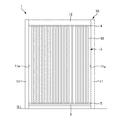
本実施形態においては、図1、図2に示すように、例えば宅地と道路との境界に設けられて空間を仕切る仕切り構造体としての自立式の縦格子ユニットを例に挙げて説明する。
Hereinafter, a partition structure according to an embodiment of the present invention will be described with reference to the drawings.
In the present embodiment, as shown in FIGS. 1 and 2, for example, a self-supporting vertical lattice unit as a partition structure that is provided at the boundary between a residential land and a road and partitions a space will be described as an example.
本実施形態の縦格子ユニット1は、互いに間隔を隔てて立設された2本の柱11及び2本の柱11の上端部間に掛け渡された上横材としての桁12を有する門型のフレーム10と、2本の柱11の下端側に掛け渡された下横材としての下胴縁2と、桁12と下胴縁2との間に設けられ、仕切り部材としての格子材30を備えたパネル体としての格子体3と、格子体3の上部及び下部を宅地側から覆う上カバー4及び下カバー5と、を有している。
The
以下の説明においては、立設されている状態の縦格子ユニット1を道路側から見たときに、上下となる方向を上下方向、左右となり縦格子ユニット1の幅方向を左右方向、左右方向と直交する方向を奥行き方向として示す。縦格子ユニット1の各部位であっても、また、縦格子ユニット1を構成する各部材については単体の状態であっても、立設されている状態にて上下方向、左右方向、奥行き方向となる方向にて方向を特定して説明する。
In the following description, when the
柱11は、断面が矩形状をなし長手方向に貫通する中空部を有する角パイプ状の部材であり、互いの一つの側面11aが対面するように配置されている。桁12は、柱11の対面する側面11aの上端部間に架け渡されて連結されている。
The
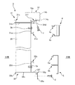
桁12は、長手方向に中空部を有する桁本体13と、桁本体13に固定されて格子体3の上部側が固定される固定部材14と、を有している。以下の説明においては、格子材30により仕切られる空間の一方側に相当する宅地側を内側、他方側に相当する道路側を外側として説明する。
The
桁本体13は、断面が矩形状をなし長手方向に貫通する中空部を有する角パイプ状の桁基幹部13aと、桁基幹部13aの長手方向に沿い鉛直面をなす両側の側板部13bと繋がって桁基幹部13aの下面13cを形成する基幹下板部13dより下方に延出された桁垂壁部13eと、を有する押出成形部材である。
The
桁垂壁部13eの下部には、互いに対向する側に突出片13fが設けられている。突出片13fは、各々の桁垂壁部13eに、上下方向に僅かに間隔を空けて2つ設けられており、内側の桁垂壁部13eに設けられた上側の突出片13fは、固定部材14の位置決め部をなし、外側の桁垂壁部13eに設けられた上側の突出片13fは、格子体3の上部が係合される上桟係合部をなしている。
A projecting
固定部材14は、桁基幹部13aの基幹下板部13dに対面して固定される固定板部14aと、固定板部14aの一方側の縁から垂設され内側の桁垂壁部13eに沿って配置される固定縦壁部14bと、固定縦壁部14bの下縁から外側に向かって低くなるように傾斜しつつ延出された上横材側延出部としての桁側延出部14cと、を有している。
The fixing
固定部材14は、固定縦壁部14bの下縁が、桁本体13の内側の桁垂壁部13eに設けられた上側の突出片13f上に載置された状態で、固定板部14aが基幹下板部13dと対面し、下方から進入するビスにより桁本体13に固定されて桁本体13とともに桁12をなしている。固定部材14が桁本体13に固定された状態で、内側の桁垂壁部13eの下端13gは、桁側延出部14cよりも下に位置している。ここで、内側の桁垂壁部13eが、桁の一方側の見付け面をなす壁部に相当する。
The fixing
下胴縁2は、長手方向に貫通する中空部を有する中空部材であり、上下方向に間隔を空けて対向する胴縁上板部2a及び胴縁下板部2bと、胴縁上板部2aと胴縁下板部2bとの外側の縁を繋ぐ胴縁外板部2cと、胴縁上板部2aと胴縁下板部2bとの内側の縁を繋ぐ胴縁内板部2dと、胴縁外板部2cと繋がって胴縁上板部2aより上方に延出された胴縁外側延出片2eと、を有している。胴縁内板部2dは、上側部分2fが下側部分2gよりも外側に位置するような段部を有している。
下胴縁2は、柱11の対面する側面11aの下端部側に、例えばアングル材などの連結部材6を介して連結されている。
The
The
格子体3は、図3に示すように、中空の角パイプ状をなす複数の格子材30と、複数の格子材30の上端部が固定される上桟31と、複数の格子材30の下端部が固定される下桟32と、を有している。上桟31及び下桟32は、押出成形部材であり、互いに上下に間隔を隔ててほぼ平行をなすように配置される。複数の格子材30は、上桟31及び下桟32の長手方向に適宜間隔を空けてほぼ平行に並べて配置され、各々の上端部が上桟31に内側から仕切り部材固定具としてのビス3aにより固定されており、各々の下端部が下桟32に内側からビス3aにより固定されている。
As shown in FIG. 3, the
上桟31は、各格子材30の内側の面が当接される鉛直面でなる上桟内壁部31aと、上桟内壁部31aの上部側の部位から外側に延出された上桟平面部31bと、上桟平面部31bの外側の端部側に設けられた上桟外係合片31cと、上桟内壁部31aの内側に突出し上カバー4が係止される上下の上カバー係止部31d、31eと、上桟内壁部31aの上側の上カバー係止部31dよりも上に設けられ固定部材14の桁側延出部14cに固定される上桟側延出部31fと、を有している。
The
上桟平面部31bは、各格子材30の上端部に当接される板状の部位であり、取り付けられた格子材30の上側の小口を覆うように構成されている。上桟外係合片31cは、上桟平面部31bから上方に突出し、桁本体13の外側の桁垂壁部13eに設けられた上側の突出片13fと係合する。上側の上カバー係止部31dは、上桟内壁部31aに対して上桟平面部31bと反対側に突出させて設けられており、下側の上カバー係止部31eは、上桟内壁部31aの下縁から内側に突出させて設けられている。
The upper
各格子材30は、上側の上カバー係止部31dと下側の上カバー係止部31eとの間にてビス3aにより固定されている。上桟側延出部31fは、上桟内壁部31aから内側に向かって高くなるように傾斜しつつ延出されている。上桟側延出部31fの傾斜角度は、桁側延出部14cの傾斜角度とほぼ一致している。
Each
下桟32は、下胴縁2の胴縁内板部2dにおける上側部分2fに内側から当接される下桟内側壁部32aと、下胴縁2の胴縁外側延出片2eの内側にて当該胴縁外側延出片2eと対向する下桟外側壁部32bと、下桟内側壁部32aの上縁と下桟外側壁部32bの上縁とを繋ぎ水平面を形成する下桟平板部32cと、下桟平板部32cから上方に延出され各格子材30の内側の面が当接される鉛直面でなる下桟上方延出部32dと、を有している。
The
下桟上方延出部32dの上端には、内側に延出された上側の下カバー係止部32eが設けられており、下桟平板部32cの下桟上方延出部32dよりも内側には上方に突出する下側の下カバー係止部32fが設けられている。また、下桟平板部32cの内側の端部には下カバー5が載置されるカバー載置部32gが設けられている。各格子材30は、上側の下カバー係止部32eと下側の下カバー係止部32fとの間にてビス3aにより固定されている。
An upper lower
上桟31及び下桟32に複数の格子材30が固定された格子体3は、上桟外係合片31cが外側の桁垂壁部13eに設けられた突出片13fに係合された状態で、桁側延出部14c上に上桟側延出部31fが重ねられて内側の下方から斜めに進入する延出部固定具としてのビス7により接合されることにより上桟31が桁12に固定されている。また、下桟の32の下桟内側壁部32aが下胴縁2の胴縁内板部2dに内側から外側に向かって進入するビス8により接合されることにより下桟32が下胴縁2に固定されている。
In the
上カバー4は、外側に上桟31に設けられた2つの上カバー係止部31d、31eに係止される被係止部4a、4bを有している。上カバー4は、被係止部4a、4bが上カバー係止部31d、31eに係止されることにより、2つの上カバー係止部31d、31eの間及び桁本体13の内側の桁垂壁部13eの下端と上側の上カバー係止部31dとの間が覆われる。このとき、格子材30を上桟31に固定するビス3a及び桁側延出部14cと上桟側延出部31fとを接合するビス7も上カバー4により覆われている。
The
下カバー5は、外側に下桟32に設けられた2つの下カバー係止部32e、32fに係止される被係止部5a、5bを有している。下カバー5は、被係止部5a、5bが下カバー係止部32e、32fに係止されることにより、上側の下カバー係止部32eから下桟内側壁部32aの下端を内側から覆うように構成されている。このとき、格子材30を下桟32に固定するビス3a及び下桟内側壁部32aと胴縁内板部2dとを接合するビス8も下カバー5により覆われている。
The
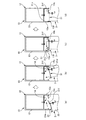
本実施形態の縦格子ユニット1の施工方法は、図4(a)に示すように、立設されたフレーム10に下胴縁2が設けられている状態で、上桟31及び下桟32に複数の格子材30が固定されている格子体3が取り付けられる。このとき、固定部材14は、桁本体13に固定されている。
As shown in FIG. 4 (a), the
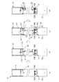
図4(b)、図5(a)に示すように、まず、格子体3を内側から、上部側が下部側より外側に位置するように傾けた状態で、桁12と下胴縁2との間に移動しつつ、上桟側延出部31fを桁側延出部14cと外側の桁垂壁部13eとの間に挿入する。
As shown in FIGS. 4B and 5A, first, the
次に、図5(b)に示すように、上桟側延出部31fを桁側延出部14cの上方に移動させ、桁側延出部14cの先端を上桟側延出部31fと上側の上カバー係止部31dとの間に挿入させる。
Next, as shown in FIG. 5 (b), the upper beam
次に、図4(c)に示すように、格子体3の下部を外側に移動させて格子体3の姿勢が鉛直になるように格子体3を回転させる。このとき、格子体3は、フレーム10に固定された後の位置よりも内側に配置されている。このとき、上桟側延出部31fが桁側延出部14c上に重なる。
Next, as shown in FIG. 4C, the lower part of the
次に、図5(c)、図5(d)に示すように、格子体3を桁側延出部14cの傾斜に沿わせて外側に移動し、上桟外係合片31cを外側の桁垂壁部13eに設けられた突出片13fに係合させる。この状態で、格子体3は、桁側延出部14cと外側の桁垂壁部13eに設けられた突出片13fとにより仮支持される。また、このとき、図4(c)下桟32は上下方向において下胴縁2と間隔を空けた状態で、下桟内側壁部32aが胴縁内板部2dの上側部分2fに内側から当接される。
Next, as shown in FIGS. 5 (c) and 5 (d), the
次に、桁側延出部14cと、桁側延出部14c上に重なっている上桟側延出部31fとを内側の下方からビス7を斜めに進入させて接合し、下桟内側壁部32aと胴縁内板部2dとを内側からビス8を外側に向かって進入させて接合する。
Next, the girder-
最後に、図3、図4(d)に示すように、上カバー4の被係止部4a、4bを上カバー係止部31d、31eに係止して上カバー4を取り付け、下カバー5の被係止部5a、5bを下カバー係止部32e、32fに係止して下カバー5を取り付け、縦格子ユニット1の施工が完了する。
Finally, as shown in FIGS. 3 and 4 (d), the
本実施形態の縦格子ユニット1によれば、格子体3の上桟31に設けられている上桟側延出部31fが桁12を構成する固定部材14に設けられている桁側延出部14cの上に重なっており、下桟32と下胴縁2とは上下方向に間隔が空けられている。このため、格子体3の上下方向の位置は下胴縁2により規制されないので、格子体3の上桟31を基準にして位置決めすることが可能である。このため、視認されやすい格子体3の上側にて位置決めされるので、格子体3を複数並べる場合であっても、ばらつきが小さいので意匠性に優れている。また、桁12の内側に設けられ外側に向かって延出された桁側延出部14cと、上桟31の内側に設けられ内側に向かって延出された上桟側延出部31fとが、桁側延出部14c側からビス7により接合されているので、ビス7は、見込み方向からは視認されにくい。このため、より意匠性に優れている。
According to the
また、桁12の桁側延出部14cと上桟31の上桟側延出部31fとがビス7により接合されて格子体3は桁12に支持されているので、たとえ下胴縁2が下方に湾曲するように変形したとしても格子体3は外れない。更に、下桟32は下胴縁2に固定されているので、格子体3をより安定した状態でより強固に保持することが可能である。このため、意匠性を損なうことなく、格子体3が外れ難い縦格子ユニット1を提供することが可能である。
また、桁12の桁側延出部14cは外側に向かって低くなる傾斜をなしているので、
格子体3を取り付ける際に、上桟31の上桟側延出部31fを、桁側延出部14cと外側の桁垂壁部13eとの間に容易に挿入することが可能である。
Further, since the girder-
Moreover, since the spar-
When attaching the
また、上桟側延出部31fを桁側延出部14c上に重ねた後に、格子体3を桁側延出部14cの傾斜に沿わせて外側に移動して上桟外係合片31cを突出片13fに係合させるので、桁側延出部14cをガイドとして格子体3を移動させることが可能である。このため、上桟外係合片31cを突出片13fに容易に係合させることが可能である。
Further, after the upper beam
さらに、桁12の桁側延出部14cは外側に向かって低くなる傾斜をなし、上桟31の上桟側延出部31fは内側に向かって高くなる傾斜をなしているので、ビス止めの工具等が格子体3に妨げられることなく、内側の下方からビス7を斜めに進入させて容易に且つ確実に接合することが可能である。このとき、格子体3は、桁側延出部14cと突出片13fとにより仮支持されているので、格子体3をより安定させることが可能であり、作業者が格子体3を支えつつビス止めする必要はない。このため、施工性に優れた縦格子ユニット1を提供することが可能である。
Further, the spar-
また、上桟側延出部31fとビス7により接合される桁側延出部14cを有する固定部材14の固定縦壁部14bが沿わされる桁本体13の内側の桁垂壁部13eは、下端13gが桁側延出部14cよりも下に位置しているので、上桟側延出部31fと桁側延出部14cとを接合しているビス7が桁垂壁部13eにより内側からより見え難くい。このため、より意匠性に優れている。
Further, the
また格子材30を上桟31に固定するビス3aも、桁側延出部14cと上桟側延出部31fとを接合するビス7も、上カバー4により覆われるので、さらに意匠性に優れた縦格子ユニット1を提供することが可能である。
Further, since the
上記実施形態においては、桁側延出部14c上に上桟側延出部31fを重ねて内側の下方からビス7にて接合している例について説明したが、これに限らず、上桟側延出部を桁側延出部の下側に重ねて接合しても構わない。
上記実施形態においては、仕切り部材として縦の格子をなす格子体3を用いた例について説明したが、これに限らず、面材、フェンスなど、空間を一方側と他方側とに仕切る部材であれば構わない。
In the above embodiment, the example in which the upper beam
In the above-described embodiment, the example using the
また、上記実施形態は、本発明の理解を容易にするためのものであり、本発明を限定して解釈するためのものではない。本発明は、その趣旨を逸脱することなく、変更、改良され得ると共に、本発明にはその等価物が含まれることはいうまでもない。 Moreover, the said embodiment is for making an understanding of this invention easy, and is not for limiting and interpreting this invention. The present invention can be changed and improved without departing from the gist thereof, and it is needless to say that the present invention includes equivalents thereof.
1 縦格子ユニット、2 下胴縁、3 格子体、3a ビス、4 上カバー、
7 ビス、12 桁、13e 桁垂壁部、13f 突出片、14c 桁側延出部、
30 格子材、31 上桟、31f 上桟側延出部、32 下桟、
1 vertical lattice unit, 2 lower trunk edge, 3 lattice body, 3a screw, 4 upper cover,
7 Screws, 12 digits, 13e Girder wall, 13f Projection piece, 14c Girder side extension,
30 lattice material, 31 upper beam, 31f upper beam side extension, 32 lower beam,
Claims (5)
前記上横材と前記下横材との間に配置され、空間を一方側と他方側とに仕切る仕切り部材、及び、前記仕切り部材が固定されている上桟及び下桟を備えたパネル体と、
を有し、
前記上横材は、前記一方側に設けられ前記他方側に向かって低くなる傾斜をなして延出された上横材側延出部を有し、
前記上桟は、前記一方側に設けられ当該一方側に向かって高くなる傾斜をなして延出された上桟側延出部を有し、
前記上桟側延出部は、前記上横材側延出部と重なり、延出部固定具により接合されていることを特徴とする仕切り構造体。 An upper cross member and a lower cross member provided at intervals in the vertical direction;
A partition member disposed between the upper cross member and the lower cross member and partitioning the space into one side and the other side; and a panel body including an upper rail and a lower rail to which the partition member is fixed; ,
Have
The upper cross member has an upper cross member-side extending portion that is provided on the one side and extends with an inclination that decreases toward the other side,
The upper rail has an upper rail-side extension portion provided on the one side and extending with an inclination increasing toward the one side,
The partition structure, wherein the upper beam side extending portion overlaps with the upper cross member side extending portion and is joined by an extending portion fixing tool.
前記上横材は、前記上横材側延出部と見込み方向に間隔を空けて前記他方側に設けられ、前記上桟が係合される上桟係合部を有していることを特徴とする仕切り構造体。 The partition structure according to claim 1,
The upper cross member has an upper beam engaging portion that is provided on the other side with a gap in the prospective direction with respect to the upper horizontal member side extending portion and to which the upper beam is engaged. A partition structure.
前記下桟は、前記下横材と上下方向に間隔が空けられた状態で前記下横材に固定されていることを特徴とする仕切り構造体。 The partition structure according to claim 1 or 2,
The said lower crosspiece is being fixed to the said lower horizontal member in the state spaced apart from the said lower horizontal member in the up-down direction, The partition structure characterized by the above-mentioned.
前記上横材は、前記一方側の見付け面をなす壁部の前記他方側に前記上横材側延出部が設けられており、前記壁部の下端は、前記上横材側延出部よりも下に位置していることを特徴とする仕切り構造体。 A partition structure according to any one of claims 1 to 3,
The upper cross member is provided with the upper cross member side extending portion on the other side of the wall portion forming the one side finding surface, and the lower end of the wall portion is formed by the upper cross member side extending portion. The partition structure characterized by being located below.
前記上桟には、前記仕切り部材が前記一方側から仕切り部材固定具により固定され、
前記延出部固定具と前記仕切り部材固定具とを覆うカバーが取り付けられていることを特徴とする仕切り構造体。
A partition structure according to any one of claims 1 to 4,
The partition member is fixed to the upper rail by a partition member fixture from the one side,
The partition structure which the cover which covers the said extension part fixing tool and the said partition member fixing tool is attached.
Priority Applications (1)
| Application Number | Priority Date | Filing Date | Title |
|---|---|---|---|
| JP2018102174A JP6961533B2 (en) | 2018-05-29 | 2018-05-29 | Partition structure |
Applications Claiming Priority (1)
| Application Number | Priority Date | Filing Date | Title |
|---|---|---|---|
| JP2018102174A JP6961533B2 (en) | 2018-05-29 | 2018-05-29 | Partition structure |
Publications (2)
| Publication Number | Publication Date |
|---|---|
| JP2019206830A true JP2019206830A (en) | 2019-12-05 |
| JP6961533B2 JP6961533B2 (en) | 2021-11-05 |
Family
ID=68768435
Family Applications (1)
| Application Number | Title | Priority Date | Filing Date |
|---|---|---|---|
| JP2018102174A Active JP6961533B2 (en) | 2018-05-29 | 2018-05-29 | Partition structure |
Country Status (1)
| Country | Link |
|---|---|
| JP (1) | JP6961533B2 (en) |
Cited By (1)
| Publication number | Priority date | Publication date | Assignee | Title |
|---|---|---|---|---|
| JP2024051487A (en) * | 2022-09-30 | 2024-04-11 | 三協立山株式会社 | Structure |
-
2018
- 2018-05-29 JP JP2018102174A patent/JP6961533B2/en active Active
Cited By (1)
| Publication number | Priority date | Publication date | Assignee | Title |
|---|---|---|---|---|
| JP2024051487A (en) * | 2022-09-30 | 2024-04-11 | 三協立山株式会社 | Structure |
Also Published As
| Publication number | Publication date |
|---|---|
| JP6961533B2 (en) | 2021-11-05 |
Similar Documents
| Publication | Publication Date | Title |
|---|---|---|
| JP6961533B2 (en) | Partition structure | |
| JP6726404B2 (en) | Rack side frame structure | |
| JP2019148077A (en) | Floor structure | |
| JP2013181348A (en) | Adjuster device in partition device | |
| JP5266115B2 (en) | Outer wall material mounting bracket and outer wall material mounting structure | |
| JP2016223174A (en) | Column fixing device for partition panel | |
| KR101029152B1 (en) | Joining structure of partition panel frame | |
| JP6711593B2 (en) | Partition panel device | |
| JP5231037B2 (en) | Panel fixture | |
| JP5168667B2 (en) | Rack frame structure | |
| JP2018031178A (en) | Field edge mounting device | |
| JPH026856Y2 (en) | ||
| JP2000213143A (en) | Corner structure of prefabricated wall | |
| KR200478698Y1 (en) | Frame set of booth assembly | |
| KR20250077974A (en) | Connecting structure of charnel house shelf | |
| JP7094720B2 (en) | Floor structure | |
| JP5835571B2 (en) | Corner shelf equipment | |
| JP2013189813A (en) | Deck, attaching member and attaching method of attaching member | |
| JP5360395B2 (en) | Rack shelf support structure | |
| JP2817630B2 (en) | Partition panel support device | |
| JP6860376B2 (en) | Lattice | |
| JP2025030610A (en) | Panel body | |
| JP6985105B2 (en) | furniture | |
| JPH0656237U (en) | Panel board mounting structure for partition devices, etc. | |
| JPH0744649Y2 (en) | Partition panel substructure |
Legal Events
| Date | Code | Title | Description |
|---|---|---|---|
| A621 | Written request for application examination |
Free format text: JAPANESE INTERMEDIATE CODE: A621 Effective date: 20201109 |
|
| TRDD | Decision of grant or rejection written | ||
| A01 | Written decision to grant a patent or to grant a registration (utility model) |
Free format text: JAPANESE INTERMEDIATE CODE: A01 Effective date: 20210921 |
|
| A61 | First payment of annual fees (during grant procedure) |
Free format text: JAPANESE INTERMEDIATE CODE: A61 Effective date: 20211013 |
|
| R150 | Certificate of patent or registration of utility model |
Ref document number: 6961533 Country of ref document: JP Free format text: JAPANESE INTERMEDIATE CODE: R150 |
|
| R250 | Receipt of annual fees |
Free format text: JAPANESE INTERMEDIATE CODE: R250 |
|
| R250 | Receipt of annual fees |
Free format text: JAPANESE INTERMEDIATE CODE: R250 |