JP2019217618A - Bottle handling device - Google Patents
Bottle handling device Download PDFInfo
- Publication number
- JP2019217618A JP2019217618A JP2018130275A JP2018130275A JP2019217618A JP 2019217618 A JP2019217618 A JP 2019217618A JP 2018130275 A JP2018130275 A JP 2018130275A JP 2018130275 A JP2018130275 A JP 2018130275A JP 2019217618 A JP2019217618 A JP 2019217618A
- Authority
- JP
- Japan
- Prior art keywords
- arm
- bottle
- claw
- tip
- cam
- Prior art date
- Legal status (The legal status is an assumption and is not a legal conclusion. Google has not performed a legal analysis and makes no representation as to the accuracy of the status listed.)
- Pending
Links
- 210000000078 claw Anatomy 0.000 claims description 37
- 238000010586 diagram Methods 0.000 abstract 1
- 230000008602 contraction Effects 0.000 description 4
- 238000001514 detection method Methods 0.000 description 2
- 239000007788 liquid Substances 0.000 description 2
- 230000001105 regulatory effect Effects 0.000 description 2
- 239000004677 Nylon Substances 0.000 description 1
- 230000000903 blocking effect Effects 0.000 description 1
- 230000001419 dependent effect Effects 0.000 description 1
- 239000011521 glass Substances 0.000 description 1
- 229920001778 nylon Polymers 0.000 description 1
- 238000012856 packing Methods 0.000 description 1
- 239000004033 plastic Substances 0.000 description 1
- 239000010409 thin film Substances 0.000 description 1
Images


Landscapes
- Manipulator (AREA)
- Wrapping Of Specific Fragile Articles (AREA)
Abstract
【課題】 装置自体には動力源がなくても、ロボットアームの先端に組付けたボトルハンドリング手段が狭いケースに整列したボトルを中から、1本ずつ取り出すことを可能にする。
【解決手段】 スカラロボット等のロボットアームの先端に組付けるボトルハンドリング手段が、ボトルネックを把持する姿勢のまま、ボトルキャップ側から一定高さまで押し込むことで、ボトルを把持し、持ち上げ移動後、再度一定の高さまで押し込むと把持状態が解除される。
【選択図】図4PROBLEM TO BE SOLVED: To enable bottle handling means attached to the tip of a robot arm to take out bottles arranged in a narrow case one by one from inside even if a device itself does not have a power source.
SOLUTION: The bottle handling means to be mounted on the tip of a robot arm such as a SCARA robot pushes the bottle cap to a certain height from the bottle cap side while holding the bottle neck, thereby grasping the bottle, lifting it up, and then moving it again. Pressing it to a certain height releases the gripping state.
[Selection diagram] FIG.
Description
本発明は、液体を収めたペットボトルやガラスボトル等を複数本収めたケースから、1本ずつボトルを取り出す装置に関する。 The present invention relates to an apparatus for taking out bottles one by one from a case containing a plurality of plastic bottles, glass bottles and the like containing liquid.
ペットボトルなどの液体を入れた容器を、複数個纏めたケースの中から1本ずつ取り出すような装置はなかった。 There is no apparatus that takes out a container containing a liquid such as a PET bottle one by one from a case in which a plurality of containers are put together.
この考案は、ボトルの箱詰め作業の高速化を図るために考案されたものである。3本のハンドリング爪をカム及びシリンダの動力で、ボトルのネック部を掴み直立後、シリンダの動力で、外す構造をとっている。This invention has been devised in order to speed up the operation of packing bottles. The structure is such that the three handling claws are gripped by the power of the cam and the cylinder, grip the neck of the bottle, stand upright, and then removed by the power of the cylinder.
解決しようとする問題点は、シリンダの動力源がなければ、駆動できない点と、収納ケース内からボトルを取り出す点であり、装置自体には動力源がなくても、1本ずつ取り出すことを可能にする。 The problem to be solved is that if there is no power source for the cylinder, it cannot be driven and the bottle is taken out of the storage case. It is possible to take out bottles one by one even if the device itself does not have a power source. To
本発明は、少なくともスカラロボット等のロボットのアームの先端に組付けるボトルハンドリング手段を、ボトルネックを把持するコンパクトな姿勢のまま、周りのボトルに触れずに、所望のボトルのボトルキャップ側から一定高さまで押し込むことで、所望のボトルを把持し、持ち上げ移動後、再度一定の高さまで押し込むと、把持状態が解除されるようにすることを最も主な特徴とする。 According to the present invention, at least a bottle handling means to be attached to a tip of a robot arm such as a SCARA robot is fixed from a bottle cap side of a desired bottle without touching surrounding bottles while keeping a compact posture for gripping a bottle neck. The most main feature is that a desired bottle is gripped by being pushed to a height, and then lifted and moved, and then pushed again to a certain height so that the gripping state is released.
この構成により、今まで、人手に頼っていた、ケースからのボトルの取り出し作業がロボットのアームの先端に組付けたこの装置により可能となる。 With this configuration, the operation of taking out the bottle from the case, which has been dependent on manual operation, can be performed by this device assembled to the tip of the arm of the robot.
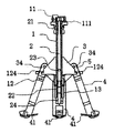
以下、図面を参照して本発明の実施形態を説明する。図1は、本発明の中央断面図であり、後述するアームが閉じた状態である。1はシリンダベース、11は図示しないロボットのアームに固定する連結部、111はアダプタ11に固定されたフォトインタラプタ、12はアームベース、124は揺動支点、13はラッチカバー、2はロッド、21はラッチバネ、22はラッチ機構(移動可能なスライドする部材に一方向の力を加えて、一定以上の距離を移動すると、その力を解除してもスライドする部材は一定の位置を保持し、再び同方向の力を更に加えた後にその力を解除すると、最初の位置まで移動後、その位置を保持する機構)、23は契合ピン、24はラッチノブ、3はカムフロアー、34はカムピン、4はアーム、41は爪、5はアームバネで、これらから構成される。 Hereinafter, embodiments of the present invention will be described with reference to the drawings. FIG. 1 is a central sectional view of the present invention, in which an arm described later is closed. 1 is a cylinder base, 11 is a connecting part fixed to a robot arm (not shown), 111 is a photo interrupter fixed to an
シリンダベース1と連結部11と、アームベース12は一体である。フォトインタラプタ111はロッド2の先端の突起の位置により、後述するアームの開閉状態を検知する検出器である。ラッチカバー13はラッチ機構22をシリンダベース1に固定するカバーである。 The
ロッド2はシリンダベース1の中にあり、ラッチ機構22とラッチバネ21に押されて上下に移動可能である。ラッチ機構22はラッチノブ24が上下に移動して一定のストローク移動することで、2つの位置(後述するカムベースが上がった上の位置とカムベースが下がった下の位置)を保持する機構である(ノック式ボールペンのラッチ機構を逆さまにした構造)。ラッチバネ21はラッチ機構を構成する。図1が上の位置の状態であり、図2が下の位置の状態である。 The
一方、カムベース3はシリンダベース1の外円筒部を上下に摺動可能で、かつ、シリンダベース1の外円筒部に設けた、ラッチ機構22で生じるストローク以上の長穴を介して、ロッド2と契合ピン23で連結されている。そのため、ロッド2に連動して上下動する。 On the other hand, the
アーム4はシリンダベース1を中心にして4つ有り、アームベース12に揺動支点124を介して揺動可能に支持されている。カムピン34はアーム4の一端に回転自在に軸支されている。 There are four
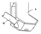
図3で下方から見た詳細図のように、爪41は半円筒形状の弾性体から出来ており、アーム4の一端部から斜め上に向かって、外円筒凸部が下になるように組付けられている。アーム4の爪41の受け面は爪41とほぼ同じ半円筒をしており、爪41に掛るボトルの荷重で折れ曲がりにくくしている。一方、アーム4が閉じた状態であっても、このような形状であるため、下側からボトルキャップ62が爪41に押し当たって来た場合でも、軽い力で曲がり、4つの爪41で形成される開口部をボトルキャップ62は無理なく通過できる。アームバネ5はリング状のゴムであり、4つのアーム4の揺動支点124より上に掛っており、アームバネ5の収縮力により、アーム4の爪41側を開く方向に力が作用している。 As shown in a detailed view seen from below in FIG. 3, the
図1で、カムベース3が上の位置にあり、カムピン34はアームバネ5の収縮力により、カムベース3の縦面に当接している。この状態で、アーム4は揺動支点124のほぼ真下に垂直になり、4つの爪41で形成される開口部は後述するボトルのネックより若干小径に閉じた状態になる。この位置では、ロッド2の上端部がフォトインタラプタ111の光を遮るので、上の位置(アーム4が閉状態)にあることが、電気信号として検知される。 In FIG. 1, the
図2はカムベース3が下の位置にあり、カムピン34はアームバネ5の収縮力により、4つのアーム4が揺動支点124で揺動して、カムベース3の斜面に当接し、4つの爪41で形成される開口部は後述するボトルのネック径より十分開いた状態になる。この位置では、ロッド2の上端部がフォトインタラプタ111の光を遮らないので、下の位置(アーム4が開状態)にあることが、電気信号として検知される。アーム4の開閉状態を検知した信号は、図示しないロボットの制御装置に送られ、その信号を基にロボットアームの動きをコントロールする。 In FIG. 2, the
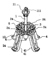
次に図4で動作を説明する。この図では手前のアーム4と爪41を省略している。6はボトル、61はボトルキャップ、62はボトルネックである。図2の状態の4つの爪41で形成される開口部より小径の図示しないダミーのボトルとしてのロッドが作業の邪魔にならない位置に垂直に立っており、そのロッドの先端の真上から、図示しないロボットアームが、図2の状態の装置を一定高さまで降下することで、装置のセンターのラッチノブ24を押し上げる。すると図2のアーム4が閉じたコンパクトな状態(図1)になる。そのため、ボトルの密集したケース内に周囲のボトルに接することなく挿入できるようになる。 Next, the operation will be described with reference to FIG. In this figure, the
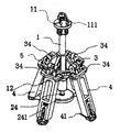
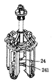
その状態のまま、ケース内の所望のボトル6の真上まで移動し、降下する。キャップ61は4つの爪41を押し広げながら通過し、4つの爪41の先端がボトルネック62に掛るまで、かつ、ラッチノブ24が下の位置に反転移動しない高さまで降下させる。次に、アームを上昇させると、ボトルネック62部は4つの爪41に引っ掛かって、ケースよりボトルを1本取り出すことができる。その後別の場所へ移動後、こんどはラッチノブ24とボトルキャップ61が当接し、ラッチ機構が反転するまでロボットアームを降下させることで、図2の状態になり、ボトルネック62と爪41の契合が外れる。図5は図2の状態を斜め上から見た装置の全体図である。 In this state, it moves to just above the desired
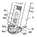
図6、図7、図8は上記実施例の改良版の説明である。同じ図番は同じ部品を示す。241はボトルキャップ受けであり、受け面を広くして、色々なボトルにより対応しやすくするために追加した。図8では 411が爪受けアーム、412は固定ネジで、アーム4から伸びる爪受けアーム411の止め位置を変えて、揺動支点124から爪41の長さを変え、固定ネジ412で固定することが出来る。413はねじりバネ、414はストッパネジ、415は固定ナット、416は爪受け、417は揺動軸である。 FIGS. 6, 7, and 8 are explanatory views of an improved version of the above embodiment. The same figure numbers indicate the same parts.
爪41は爪受け416に図示しないネジで416からの飛び出し量を調整して固定出来る。爪受け416は揺動軸417を支点にして揺動自在に保持され、ねじりバネ413でアーム4に対し、爪41が開くように付勢されている。爪受け416の爪41の反対側にストッパネジ414の先端が当たることで、アーム4と爪41の開き角度が規制される。爪受け416との当たり位置を調整後、固定ナット415で固定する。各4本のアーム4の先端部は同じ構造にしてある。 The
爪41の剛性を上げても、ねじりバネ413を追加したことで、重いボトルの場合であっても、アーム4が閉じた状態で、ボトルを押し込む時、軽く爪受け416が揺動して爪41が変形しなくても、逃がすことが出来る。
ボトルキャップ受けと、アーム4の長さ調整と、爪41の角度の調整と、爪の長さの調整と爪の揺動機構を追加したことで、いろいろなボトルのサイズやボトル形状や重さにも対応できるようになった。Even if the rigidity of the
By adding a bottle cap receiver,
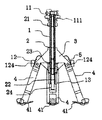
図9、図10は実施例2の、中央断面図である。この実施例では実施例1と基本構成は同じであるが、違いを以下に述べる。アーム4の揺動中心124はカムベース3の端部に在り、アーム4はロッド2と一緒に移動する。また、アームバネ5は揺動中心124より上部に位置していて、アームバネ5の収縮力で、常にアーム4は開こうとしている。アーム4が上の位置に移動する時、アーム4の側面はアームベース12の枠内面に当接しながら上がる為、アームベース12の枠内面に規制され、閉じる。つまり、アームベース2の枠の開口部とアーム4の上下の相対位置に対し、アーム4の開閉がコントロールされる。 9 and 10 are central sectional views of the second embodiment. In this embodiment, the basic configuration is the same as that of the first embodiment, but differences will be described below. The
このように、ラッチ機構22により、ボトルネック62を保持する爪41を持った複数のアーム4が開閉することで、ケースからのボトルの取り出し作業は可能となる。 As described above, the plurality of
実施例では爪41の付いた開閉部であるアーム4は4つで構成しているが、2つや3つで構成しても良い。また、アーム4と爪41は別体であったが、上記の機能を持てば、一体で有っても良い。アームの揺動支点も実施例では穴とピンの組合せであるが、支持部(カムベース)と被回転部(アーム)をPPやナイロン等で構成した場合、薄い膜状で繋がれば、揺動支点としての機能をもつので、一体化することで、部品削減が可能となる。 In the embodiment, the
実施例では位置検知手段はロッドの先端部がフォトインタラプタの光を遮ることで、間接的にアームの開閉状態を検知したが、揺動するアームの一部でフォトインタラプタの光を遮る位置にフォトインタラプタを配置して、直接的にアームの開閉状態を検知しても良い。 In the embodiment, the position detecting means indirectly detects the open / closed state of the arm by blocking the light of the photo-interrupter at the tip of the rod. However, the position detecting means is located at a position where the light of the photo-interrupter is blocked by a part of the swinging arm. An open / close state of the arm may be directly detected by disposing an interrupter.
また、ロッドの位置検知手段は、コンピュータで用いるレーザーマウスの移動量検知機構でロッドの先端の移動量を検知すれば、間接的にラッチ機構の位置や動きが正確に検知できるのでその検知結果を元に、アームが閉じた状態で、ボトルを掴む動作やアームの開閉動作が正確にできるようになる。 In addition, if the position detection means of the rod detects the amount of movement of the tip of the rod with the movement amount detection mechanism of the laser mouse used in the computer, the position and movement of the latch mechanism can be indirectly accurately detected. Originally, the operation of grasping the bottle and the operation of opening and closing the arm can be performed accurately with the arm closed.
以上のように構成することで、ケース内に詰め込まれたボトルを1本ずつ、本発明の装置を取り付けたロボットアームにより、取り出すことが可能となる。 With the above configuration, the bottles packed in the case can be taken out one by one by the robot arm equipped with the device of the present invention.
1 シリンダベース
11 連結部
111 フォトインタラプタ
12 アームベース
124 揺動支点
2 ロッド
21 ラッチバネ
22 ラッチ機構
23 契合ピン
24 ラッチノブ
3 カムベース
34 カムコロ
4 アーム
41 爪
5 アームバネDESCRIPTION OF
Claims (4)
Priority Applications (1)
| Application Number | Priority Date | Filing Date | Title |
|---|---|---|---|
| JP2018130275A JP2019217618A (en) | 2018-06-21 | 2018-06-21 | Bottle handling device |
Applications Claiming Priority (1)
| Application Number | Priority Date | Filing Date | Title |
|---|---|---|---|
| JP2018130275A JP2019217618A (en) | 2018-06-21 | 2018-06-21 | Bottle handling device |
Publications (1)
| Publication Number | Publication Date |
|---|---|
| JP2019217618A true JP2019217618A (en) | 2019-12-26 |
Family
ID=69095093
Family Applications (1)
| Application Number | Title | Priority Date | Filing Date |
|---|---|---|---|
| JP2018130275A Pending JP2019217618A (en) | 2018-06-21 | 2018-06-21 | Bottle handling device |
Country Status (1)
| Country | Link |
|---|---|
| JP (1) | JP2019217618A (en) |
-
2018
- 2018-06-21 JP JP2018130275A patent/JP2019217618A/en active Pending
Similar Documents
| Publication | Publication Date | Title |
|---|---|---|
| CN104108671B (en) | Sample preparation system with rotatable clamper | |
| JP2013152214A (en) | Sample container handling method and sample container handling apparatus | |
| JP6872909B2 (en) | Device for lifting the sample tube | |
| US4099441A (en) | Holder for guitars and the like | |
| US20110089709A1 (en) | Gripper Apparatus and Method for Containers of Different Sizes | |
| WO2016012439A1 (en) | Cup catcher device | |
| JP2020099964A (en) | End effector and robot equipped with it | |
| US20170166388A1 (en) | Test-strip storage vial | |
| CN208631001U (en) | Gripping device for tail infusion fluid bag | |
| JP2019217618A (en) | Bottle handling device | |
| US20050269469A1 (en) | Paint brush holder consisting of one part | |
| US2936192A (en) | Appliance for transferring a rouleau of can covers from a container to the magazine of a canning machine | |
| JP2023130116A (en) | Robot hand and picking robot system | |
| CN113715053A (en) | Self-adaptive clamping structure and robot | |
| KR101241376B1 (en) | Opener for Micro-Tube | |
| JPH10310492A5 (en) | ||
| US20060219058A1 (en) | Bottle Opener | |
| CN109502060B (en) | Intelligent medicine dispensing terminal tray cover closing device | |
| CN107416719A (en) | Fixture and handling device | |
| CN219906016U (en) | Cover removal tool | |
| JP3101355U (en) | Bottle container clamping device for heavy duty filling equipment | |
| JPS6234706Y2 (en) | ||
| JP3214320U (en) | Manual handle mechanism | |
| CN221796173U (en) | Photoresist bottle protection device | |
| CN211639950U (en) | Flat-open manipulator |