JP2019528131A - Device for transporting and rotating objects - Google Patents
Device for transporting and rotating objects Download PDFInfo
- Publication number
- JP2019528131A JP2019528131A JP2019511448A JP2019511448A JP2019528131A JP 2019528131 A JP2019528131 A JP 2019528131A JP 2019511448 A JP2019511448 A JP 2019511448A JP 2019511448 A JP2019511448 A JP 2019511448A JP 2019528131 A JP2019528131 A JP 2019528131A
- Authority
- JP
- Japan
- Prior art keywords
- holding
- slide
- rotor
- wheels
- pair
- Prior art date
- Legal status (The legal status is an assumption and is not a legal conclusion. Google has not performed a legal analysis and makes no representation as to the accuracy of the status listed.)
- Granted
Links
Images



Classifications
-
- B—PERFORMING OPERATIONS; TRANSPORTING
- B65—CONVEYING; PACKING; STORING; HANDLING THIN OR FILAMENTARY MATERIAL
- B65G—TRANSPORT OR STORAGE DEVICES, e.g. CONVEYORS FOR LOADING OR TIPPING, SHOP CONVEYOR SYSTEMS OR PNEUMATIC TUBE CONVEYORS
- B65G47/00—Article or material-handling devices associated with conveyors; Methods employing such devices
- B65G47/22—Devices influencing the relative position or the attitude of articles during transit by conveyors
- B65G47/24—Devices influencing the relative position or the attitude of articles during transit by conveyors orientating the articles
- B65G47/244—Devices influencing the relative position or the attitude of articles during transit by conveyors orientating the articles by turning them about an axis substantially perpendicular to the conveying plane
-
- A—HUMAN NECESSITIES
- A61—MEDICAL OR VETERINARY SCIENCE; HYGIENE
- A61F—FILTERS IMPLANTABLE INTO BLOOD VESSELS; PROSTHESES; DEVICES PROVIDING PATENCY TO, OR PREVENTING COLLAPSING OF, TUBULAR STRUCTURES OF THE BODY, e.g. STENTS; ORTHOPAEDIC, NURSING OR CONTRACEPTIVE DEVICES; FOMENTATION; TREATMENT OR PROTECTION OF EYES OR EARS; BANDAGES, DRESSINGS OR ABSORBENT PADS; FIRST-AID KITS
- A61F13/00—Bandages or dressings; Absorbent pads
- A61F13/15—Absorbent pads, e.g. sanitary towels, swabs or tampons for external or internal application to the body; Supporting or fastening means therefor; Tampon applicators
- A61F13/15577—Apparatus or processes for manufacturing
- A61F13/15764—Transferring, feeding or handling devices; Drives
-
- B—PERFORMING OPERATIONS; TRANSPORTING
- B65—CONVEYING; PACKING; STORING; HANDLING THIN OR FILAMENTARY MATERIAL
- B65G—TRANSPORT OR STORAGE DEVICES, e.g. CONVEYORS FOR LOADING OR TIPPING, SHOP CONVEYOR SYSTEMS OR PNEUMATIC TUBE CONVEYORS
- B65G47/00—Article or material-handling devices associated with conveyors; Methods employing such devices
- B65G47/74—Feeding, transfer, or discharging devices of particular kinds or types
- B65G47/84—Star-shaped wheels or devices having endless travelling belts or chains, the wheels or devices being equipped with article-engaging elements
- B65G47/846—Star-shaped wheels or wheels equipped with article-engaging elements
-
- B—PERFORMING OPERATIONS; TRANSPORTING
- B65—CONVEYING; PACKING; STORING; HANDLING THIN OR FILAMENTARY MATERIAL
- B65G—TRANSPORT OR STORAGE DEVICES, e.g. CONVEYORS FOR LOADING OR TIPPING, SHOP CONVEYOR SYSTEMS OR PNEUMATIC TUBE CONVEYORS
- B65G47/00—Article or material-handling devices associated with conveyors; Methods employing such devices
- B65G47/74—Feeding, transfer, or discharging devices of particular kinds or types
- B65G47/84—Star-shaped wheels or devices having endless travelling belts or chains, the wheels or devices being equipped with article-engaging elements
- B65G47/846—Star-shaped wheels or wheels equipped with article-engaging elements
- B65G47/848—Star-shaped wheels or wheels equipped with article-engaging elements the article-engaging elements being suction or magnetic means
-
- B—PERFORMING OPERATIONS; TRANSPORTING
- B65—CONVEYING; PACKING; STORING; HANDLING THIN OR FILAMENTARY MATERIAL
- B65H—HANDLING THIN OR FILAMENTARY MATERIAL, e.g. SHEETS, WEBS, CABLES
- B65H5/00—Feeding articles separated from piles; Feeding articles to machines
- B65H5/08—Feeding articles separated from piles; Feeding articles to machines by grippers, e.g. suction grippers
- B65H5/10—Reciprocating or oscillating grippers, e.g. suction or gripper tables
-
- B—PERFORMING OPERATIONS; TRANSPORTING
- B65—CONVEYING; PACKING; STORING; HANDLING THIN OR FILAMENTARY MATERIAL
- B65G—TRANSPORT OR STORAGE DEVICES, e.g. CONVEYORS FOR LOADING OR TIPPING, SHOP CONVEYOR SYSTEMS OR PNEUMATIC TUBE CONVEYORS
- B65G2201/00—Indexing codes relating to handling devices, e.g. conveyors, characterised by the type of product or load being conveyed or handled
- B65G2201/02—Articles
-
- B—PERFORMING OPERATIONS; TRANSPORTING
- B65—CONVEYING; PACKING; STORING; HANDLING THIN OR FILAMENTARY MATERIAL
- B65H—HANDLING THIN OR FILAMENTARY MATERIAL, e.g. SHEETS, WEBS, CABLES
- B65H2701/00—Handled material; Storage means
- B65H2701/10—Handled articles or webs
- B65H2701/19—Specific article or web
- B65H2701/1924—Napkins or tissues, e.g. dressings, toweling, serviettes, kitchen paper and compresses
Landscapes
- Engineering & Computer Science (AREA)
- Health & Medical Sciences (AREA)
- Mechanical Engineering (AREA)
- Life Sciences & Earth Sciences (AREA)
- General Health & Medical Sciences (AREA)
- Biomedical Technology (AREA)
- Heart & Thoracic Surgery (AREA)
- Vascular Medicine (AREA)
- Manufacturing & Machinery (AREA)
- Animal Behavior & Ethology (AREA)
- Epidemiology (AREA)
- Public Health (AREA)
- Veterinary Medicine (AREA)
- Specific Conveyance Elements (AREA)
- Absorbent Articles And Supports Therefor (AREA)
- Auxiliary Devices For And Details Of Packaging Control (AREA)
- Vending Machines For Individual Products (AREA)
Abstract
物体(3)を環状移送経路(T)に沿って保持ステーション(4)から解放ステーション(6)に移送し回転させる装置(7)であって、物体(3)、は保持ステーション(4)において、解放ステーション(6)における第2の配向とは異なる第1の配向を有し、装置は、第1のカムプロファイル(12)が形成された横方向表面(25)を有するリボリューションボディ(24)を有するステータ(8)と、ステータ(8)に対して第1の回転軸線(R1)を中心に回転可能であるロータ(9)と、ロータ(9)に連結された、物体(3)の少なくとも1つの保持ヘッド(10)であって、ロータ(9)に対して、第2の回転軸線(R2)の周りで回転することができる第1のカムプロファイル(12)に連結された保持要素(11)を有する、保持ヘッドと、を備え、ステータ(8)は、第2のカムプロファイル(14)を含み、移送および回転装置(7)は、移送経路(T)に沿って配設された少なくとも第1の環状ガイド(15)を有し、ヘッド(10)は、保持要素(11)を支持する少なくとも1つの第1のスライド(16)を有し、第1の環状ガイド(15)に摺動可能に連結され、第1のスライド(16)は、第1の環状ガイド(16)内への第1のスライド(16)の摺動を誘発するために第2のカムプロファイル(14)に連結されたそれぞれの角度位置変動機構(17)によってロータ(9)に連結される、装置。A device (7) for transferring and rotating an object (3) from a holding station (4) to a release station (6) along an annular transfer path (T), the object (3) being at the holding station (4) , Having a first orientation different from the second orientation at the release station (6), the device comprises a revolution body (24) having a lateral surface (25) on which a first cam profile (12) is formed. ) Having a stator (8), a rotor (9) rotatable about the first rotation axis (R1) with respect to the stator (8), and an object (3) connected to the rotor (9) At least one holding head (10) connected to a first cam profile (12) capable of rotating about a second rotational axis (R2) relative to the rotor (9) Element (11) The stator (8) includes a second cam profile (14), and the transfer and rotation device (7) is at least first disposed along the transfer path (T). The head (10) has at least one first slide (16) supporting the holding element (11) and is slidable on the first annular guide (15). And the first slide (16) is connected to the second cam profile (14) to induce sliding of the first slide (16) into the first annular guide (16). A device connected to the rotor (9) by a respective angular position variation mechanism (17).
Description
本発明は、特に小寸法の、例えば吸収性物品を製造するためのベース構成要素などの少なくとも1つの物体を、物体の配向をその間で変更することを可能にする2つの作動ステーション間で移送し、回転させるための装置に関する。 The present invention transfers at least one object, such as a base component for producing absorbent articles, in particular of small dimensions, between two operating stations that allow the orientation of the object to be changed between them. Relates to a device for rotating.
詳細には、本発明は、衛生吸収性物品を実現するための包装機に含まれる移送および回転装置に関する。 Specifically, the present invention relates to a transfer and rotation device included in a packaging machine for realizing a hygiene absorbent article.
よく知られているように、生理用品、特に乳児用おむつ、生理用ナプキンまたは大人用失禁用製品は、不織布の層とポリエチレンのような防水層とに囲まれた吸収性パッドの層を含む。これらの要素は、吸収性物品の基本要素である。上述のこれらの基本的な構成要素に加えて、吸収性物品は、さらに、構造と共に実現を複雑にするさらなる追加の構成要素(例えば、弾性バンド、糞便バリアおよびサイドウィングなど)を含む。 As is well known, sanitary products, particularly baby diapers, sanitary napkins or adult incontinence products include a layer of absorbent pad surrounded by a non-woven layer and a waterproof layer such as polyethylene. These elements are basic elements of the absorbent article. In addition to these basic components described above, the absorbent article further includes further additional components (eg, elastic bands, fecal barriers, side wings, etc.) that complicate implementation with the structure.
生理用吸収性物品を製造するための既知のタイプの包装機は、不透明材料の連続ストリップの前進ラインを含み、このラインに沿って、吸収性物品を完成させるよう意図された基本構成要素および追加の構成要素の両方の連続ウェブを送り出す複数の作動ユニットが配設される。 A known type of packaging machine for manufacturing sanitary absorbent articles includes an advance line of a continuous strip of opaque material along which basic components and additions intended to complete the absorbent article A plurality of actuating units are arranged to deliver both continuous webs of the components.
各作動ユニットは、構成要素を受け入れ、この構成要素を(例えば、構成要素が処理装置に連続ストリップとして供給される場合は構成要素を個別の長さに切断することによって)処理する処理装置と、処理が終わった後に処理装置から構成要素を受け入れ、構成要素を第1の配向に持ち上げ、これを、第1の配向に対して回転させた第2の配向で解放することにより、構成要素を不透明材料のストリップに適用する、移送および回転装置とを備える。 Each actuating unit receives a component and processes the component (eg, by cutting the component into individual lengths if the component is supplied as a continuous strip to the processor); The component is made opaque by receiving the component from the processing apparatus after the processing is finished, lifting the component to the first orientation and releasing it in the second orientation rotated relative to the first orientation. A transfer and rotation device applied to the strip of material.
一般に、移送および回転装置は、中心回転軸線の周りに回転し、移送中の構成要素を保持するための複数の吸引保持ヘッドを、複数の半径方向に延びるアームによって、保持する、中央ドラムを備える。各吸着保持ヘッドは、さらに中央ドラム自体に対して回転して、基本構成要素が移送要素によって受け入れられるピックアップステーションと、基本構成要素が後続装置に解放される解放ステーションと、の間で構成要素の配向を変えることができる。 In general, the transfer and rotation device comprises a central drum that rotates about a central axis of rotation and holds a plurality of suction holding heads for holding the components being transferred by a plurality of radially extending arms. . Each suction holding head further rotates with respect to the central drum itself, between the pick-up station where the basic component is received by the transfer element and the release station where the basic component is released to the subsequent device. The orientation can be changed.
中央ドラムの回転中、ドラム自体の回転軸線に対する吸引保持ヘッドの位置は、保持ヘッド自体の線速度を変更するために、ピックアップステーションにおける第1の半径と解放ステーションにおける第2の半径との間で半径方向に変更されて、そして、ピックアップステーションから解放ステーションへの移送中の構成要素を加速または減速する。 During the rotation of the central drum, the position of the suction holding head relative to the axis of rotation of the drum itself is between a first radius at the pick-up station and a second radius at the release station in order to change the linear velocity of the holding head itself. It is changed radially and then accelerates or decelerates the component being transferred from the pick-up station to the release station.
このようにして、一連の基本構成要素を、一般にステップまたは「ピッチ」とも呼ばれる一定の間隔で構成要素が離間されたピックアップステーションからピックアップし、この構成要素を、異なる間隔で構成要素が離間される解放ステーションに送ることができる。 In this way, a series of basic components are picked up from pick-up stations that are spaced apart at regular intervals, also commonly referred to as steps or “pitch”, and the components are spaced apart at different intervals. Can be sent to the release station.
中央ドラムに対する半径方向アームの回転、半径方向アームに対する保持ヘッドの回転、および各保持ヘッドの半径方向位置の変化は、それぞれの駆動カムによって、機械的に制御される。 The rotation of the radial arm relative to the central drum, the rotation of the holding head relative to the radial arm, and the change in the radial position of each holding head are mechanically controlled by respective drive cams.
各保持ヘッドの半径方向位置の変動は、保持ヘッドに過度の応力を生じさせ、次いで、この保持ヘッドを過度に摩耗させ、それによって、破損または望ましくない誤動作を招く可能性がある。 Variations in the radial position of each holding head can cause excessive stress on the holding head, which in turn can cause excessive wear on the holding head, thereby leading to breakage or undesirable malfunction.
さらに、フォーマット変更作業中、すなわち、包装されるべき衛生吸収性物品の種類を変えるために包装機を変更する作業中に、吸引保持ヘッドの動作の法則を、処理される構成要素の異なるサイズおよび/または場所にこの動作の法則を適応させるために、修正することがしばしば必要である。 In addition, during the format change operation, i.e. during the operation of changing the packaging machine to change the type of sanitary absorbent article to be packaged, the law of operation of the suction holding head is changed to the different sizes and Modifications are often necessary to adapt this law of operation to the location.
保持ヘッドの動作の法則を修正することは、いくつかの機械的構成要素、典型的には少なくとも対応するカムの交換を必要とし、そのような交換は、カム自体を移送および回転装置のベース方向に位置決めすることにより特に長く、複雑であり、これには、多数の追加の機械的構成要素の分解およびそれに続く組み立て、ならびに、かなり長い構成ステップを必要とし、熟練した技術者の介入を必要とする。 Modifying the law of operation of the holding head requires the replacement of several mechanical components, typically at least the corresponding cam, such a replacement of the cam itself and the base direction of the rotating device Is particularly long and complex, which requires the disassembly and subsequent assembly of a number of additional mechanical components, as well as the lengthy construction steps, requiring the intervention of skilled technicians. To do.
欧州特許出願公開第2659869A1号明細書は、請求項1のプリアンブルにある装置を開示している。
本発明の目的は、上述の欠点がなく、特に製造が簡単で経済的である、物体を移送し回転させるための装置を提供することである。 The object of the present invention is to provide an apparatus for transporting and rotating an object which does not have the above-mentioned drawbacks and is particularly simple and economical to manufacture.
さらなる目的は、機械構成要素の起こり得る摩耗を低減しながら、物体を移送し回転させ、したがって、従来技術よりも長い作動寿命を有する、物体を移送し回転させるための装置を提供することである。 A further object is to provide an apparatus for transporting and rotating an object that transports and rotates the object while reducing the possible wear of the machine components and thus has a longer operating life than the prior art. .
本発明によれば、添付の特許請求の範囲に記載するような、物体を移送し回転させるための装置が提供される。 According to the present invention there is provided an apparatus for transporting and rotating an object as set forth in the appended claims.
本発明は、次に、添付の図を参照しながら説明されるが、これらの図面は、例示的であって、限定的ではない実施形態を例示している。 The present invention will now be described with reference to the attached figures, which illustrate exemplary and non-limiting embodiments.
この説明では、図示する実施形態と共通の同様の要素は同じ番号で示されている。 In this description, similar elements in common with the illustrated embodiment are indicated with the same numbers.
図9に示すように、衛生用品製造用包装機を全体的に1で示す。包装機1は、連続して処理経路P1に沿って複数の物体3、特に衛生用品を構成するための構成要素または追加の構成要素を保持ステーション4に供給する処理装置2を備える。処理装置2および生理用品を製造するための構成要素についての詳細は、これまでに既に提供されており、本明細書では繰り返さない。
As shown in FIG. 9, a sanitary ware manufacturing packaging machine is indicated generally by 1. The packaging machine 1 includes a
包装機1はまた、解放ステーション6から連続的に物体3を受け入れ、それらを供給経路P2に沿って移動させる不透明材料の連続ストリップ(図示せず)の前進ライン5を備える。
The packaging machine 1 also comprises an
物体3が、保持ステーション4において、解放ステーション6における第2の配向とは異なる、第1の配向を有することに留意されたい。
Note that the
各物体が長手方向軸線O、または、広展開軸線(an axis of prevalent development)Oを有すると仮定すると、第1の配向は、処理経路P1に対する長手方向軸線Oの配置によって与えられ、第2の配向は、供給経路P2に対する長手方向軸線Oの配置によって与えられる。 Assuming that each object has a longitudinal axis O, or an axis of pre-developed development O, the first orientation is given by the placement of the longitudinal axis O relative to the treatment path P1, the second The orientation is given by the arrangement of the longitudinal axis O relative to the supply path P2.
保持ステーション4では、物体3は、供給経路P1と平行な長手方向軸線Oを有し、距離D1だけ離間しており、一方、解放ステーション6では、各物体3の長手方向軸線Oは、前進経路P2に垂直であり、物体3は、回転させられ、距離D2だけ離間させられる。
In the holding station 4, the
包装機1は、環状移送経路Tに沿って少なくとも1つの物体3を保持ステーション4から解放ステーション6へ移送および回転させるための移送および回転装置7を備える。
The packaging machine 1 comprises a transfer and
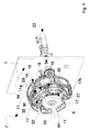
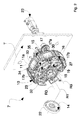
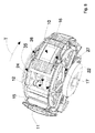
図1から図8に詳細に示すように、移送および回転装置7は、外側面25を有するリボリューションボディ(a revolution body)24を有するステータ8(図6)と、ステータ8に対して第1の回転軸線R1を中心に回転可能であるロータ9(図1、2、3および7)と、を備える。
As shown in detail in FIG. 1 to FIG. 8, the transfer and
ロータ9は、ロータ9に連結された、物体3の少なくとも1つの保持ヘッド10を含み、この保持ヘッド10は、このロータ9に対して第2の回転軸線R2(図5)を中心に回転可能なそれぞれの保持要素11を備える。保持ヘッド10は、保持ステーション4において処理装置2から物体3を受け入れ、ロータ9の回転中に物体3を第1の配向から第2の配向に回転させながら、物体3を移送経路Tに沿って前進ライン5の解放ステーション6に移送する。
The
保持要素11は、物体3と共働できるように成形される。図1〜図7に示す実施形態では、保持要素11は、外側に凸状であり、図示していないが知られている、空気吸引装置による物体の保持および輸送を可能にするために表面開口部11aを有する。換言すれば、保持ヘッド10は、保持吸引ヘッドである。
The
ステータ8は、側面25に実現されている第1のカムプロファイル12(図6)を含み、保持ヘッド10には、第1のカムプロファイル12と共働し、これに連結された対応する第1の従動子13、例えばローラが設けられている。第1の従動子13は、第1のカムプロファイル12に対する第1の従動子13の相対位置に応じて、第2の回転軸線R2の周りで保持要素11を回転させるのに適している。
The
また、ステータ8は、第2のカムプロファイル14を備えており、その詳細は以下のとおりである。
Further, the
図1から図7に示すように、移送および回転装置7は、移送経路Tに沿って配置された少なくとも第1の環状ガイド15を備え、保持ヘッド10は、保持要素11を支持し、第1の環状ガイド15に摺動可能に連結された少なくとも第1のスライド16を備える。
As shown in FIGS. 1 to 7, the transfer and
第1のスライド16は、ロータ9に対する保持ヘッド10の角度位置のそれぞれの変動機構17によってロータ9に連結されており、この変動機構17は、第2のカムプロファイル14と共働し、これに連結されて、第2のカムプロファイル14に対する変動機構17の相対位置に応じて、第1の環状ガイド15内で第1のスライド16を摺動させる。
The
第1の環状ガイド15は、ロータ9に固定されており、ロータ9と一体的にステータ8に対して回転可能である。
The first
変動機構17は、ロータ9の第1の回転軸線R1と平行な第3の回転軸線R3を有する回転ピボット18に対して振動する。変動機構17は、第2のカムプロファイル14に連結されるのに適した、第2の従動子19、例えば添付の図のようなローラを有する第1の端部17aと、第1のスライド16に締め付けられた第2の端部17bと、を有する。
The
変動機構17は、実質的に三角形のプレートを備え、回転ピボット18は、頂点に置かれ、変動機構17の第1の端部17aおよび第2の端部17bは、頂点から延びるそれぞれの第1のアームおよび第2のアームのそれぞれの端部に配置される。
The
また、ステータ8は、前壁22を有し、第2のカムプロファイル14は、前壁22の溝によって実現される平坦なカムを備える。
The
移送および回転装置7は、装置の台座の向こう側に置かれ、駆動ギアによってロータ9に知られている方法で連結されたモータ23(図1および図2)を備える。
The transfer and
図6に詳細に示すステータ8のリボリューションボディ24は、球円錐形になるように成形され、すなわちこれは、ロータ9の第1の回転軸線R1に対応する対称軸を有する端部で先細になっている球面を有する。
第4の回転軸線R4に沿って軸方向に延びる第1のカム従動子13は、互いに傾斜した2つの部分を有するレバー26を介して、レバー26自体に連結された第1の端部と、保持要素11が締め付けられる第2の端部(図示せず)との間を延びる回転軸41(図6)に連結されている。回転軸41は、第2の回転軸線R2に対して回転可能であるので、それぞれの第1のカムプロファイル12内での第1の従動子13のあらゆる移動は、保持要素11の、それ自体の第2の回転軸線R2を中心とする対応する回転に追従する。保持要素11の第2の回転軸線R2および第1のカム従動子13の第4の回転軸線R4は、互いに交差し、また交差点では、ロータ9の第1の回転軸線R1にも交差する。
The
これは、リボリューションボディ24およびレバー26の特定の形状によるものであり、前者は、錐台形タイプのものであり、後者は、互いに傾斜した部分を有する。
This is due to the specific shape of the
詳細には、リボリューションボディ24、第1のカムプロファイル12および第1の従動子13、ロータ9の第1の回転軸線R1、保持要素11の第2の回転軸線R2、および第1の従動子13の第4の回転軸線R4の間の特定の相互配置は、一般性を失うことなく引用され本明細書に組み込まれる国際出願第2014/167369号パンフレットに示されるような既知のタイプのものである。
Specifically, the
図8に示すように、ロータ9は、特に、リボリューションボディ24と前壁22との間に介在する本体27を備えることができる。本体27は、環状でもよい。第1の環状ガイド15は、本体27とリボリューションボディ24との間に介在する。
As shown in FIG. 8, the
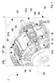
より詳細には、図4および図5に示すように、第1の環状ガイド15は、互いに対向する2つのそれぞれの転動面28aおよび28bを備えた、特にV字形断面を有する外縁28を備える。第1のスライド16は、移送経路Tに沿って互いに離間した第1の対のホイール29と第2の対のホイール30とを備え、これらは、外縁28上を摺動するように第1のスライド16にあそびを有して装着されている。第1の対のホイール29は、移送経路Tに沿って第2の対のホイール30の下流にある。各対のホイール29および30のホイールは、第1の環状ガイド15の外縁28のそれぞれの転動面28aおよび28bに沿って転動するように同軸に配置される。
More specifically, as shown in FIGS. 4 and 5, the first
さらに、第1の環状ガイド15はまた、ロータ9の第1の回転軸線R1に対して、外縁28よりも小さい距離を有する内縁31を含み、内縁も、互いに対向する2つのそれぞれの転動面31a、31bを備える。第1のスライド16は、さらに、内縁31上を摺動するように第1のスライド16上にあそびを有して装着された第3の対のホイール32を備える。第3の対のホイール32は、互いに同軸であり、内縁31のそれぞれの転動面31a、31bに沿ってそれぞれ転動するように配置される。
Furthermore, the first
第3の対のホイール32は、移送経路Tに沿って第1の対のホイール29と第2の対のホイール30との間に介在する。第1の対のホイール29、第2の対のホイール30、および第3の対のホイール32を、第3の対のホイール32が頂点を画定するロータ9の第1の回転軸線R1に面する三角形の各頂点に配置することにより、外縁28上と内縁31上両方でのスライド16の同時摺動、そして、摺動中の第1のスライド16の最適な安定性が確実になる。
The third pair of
第1のスライド16は、第1の対のホイール29、第2の対のホイール30、および第3の対のホイール32がそれぞれ締め付けられたブラケット33を備え、第1の対のホイール29および第2の対のホイール30は、ロータ9の第1の回転軸線R1に対して、第3の対のホイール32よりも外側に締め付けられる。
The
加えて、第1のスライド16は締め付けピン34を含み、この締め付けピン34は、ブラケット33に締め付けられた第1の端部と、変動機構17の第2の端部17bに固定された第2の端部とを有することに留意されたい。
In addition, the
締め付けピン34は、移送経路Tに沿って第1の対のホイール29と第2の対のホイール30との間に介在し、それにより、第2の端部17bは、第1のスライド16のほぼ中央位置に固定されて、最適な摺動を確実にする。
The clamping
移送および回転装置7はまた、第2の環状ガイド35を備え、ステータ8のリボリューションボディ24が、第1の環状ガイド15と第2の環状ガイド35との間に介在することが留意される。
It is noted that the transfer and
保持ヘッド10はまた、保持要素11を支持し、第2の環状ガイド35に摺動可能に連結された第2のスライド36(図4、5、6および7)を備える。加えて、保持ヘッド10はまた、特に矩形の支持ベース37を備え、この第1の対向する側部37aには、第1のスライド16および第2のスライド36がそれぞれ固定されている。
The holding
第2の環状ガイド35は、第1の環状ガイド15と同様であると共に、第2のスライド36は第1のスライド16と同様である。
The second
次いで、第2のスライド36の第1の対のホイール38および第2の対のホイール39が第2のスライド36にあそびを有して取り付けられて、第2の環状ガイド35の外縁44上を摺動し、一方で第3の対のホイール40が、第2のスライド36上にあそびを有して装着されて、第2の環状ガイド35の内縁45上を摺動する。第1のスライド16と第2のスライド36との間の唯一の違いは、第2のスライド36に変動機構17の締め付けピン34がないことである。
A first pair of
第2のスライド36は、第1の対のホイール38、第2の対のホイール39、および第3の対のホイール40が固定されたそれぞれのブラケット46を備え、第1の対のホイール38および第2の対のホイール39は、第1のスライド16について既に述べたのと同様の方法で、ロータ9の第1の回転軸線R1に対して、第3の対のホイール40よりも外側に固定される。
The
第1のスライド16のブラケット33および第2のスライド36のブラケット46は、支持ベース37の第1の対向する側部37aに横方向に固定されている。
The
このようにして、支持ベース37、第1のスライド16および第2のスライド36は、第1の環状ガイド15上および第2の環状ガイド35上を摺動可能である保持要素11の支持キャリッジを画定する。
In this way, the
図7に詳細に示すように、支持ベース37は、保持要素11が固定される回転軸41を収容するための穴を有する。回転軸41は、保持要素11の第2の回転軸線R2に沿って軸方向に延び、環状軸受けを介して支持ベース37に固定され、この軸受けは、保持要素11と一体の回転軸41が支持ベース37に対して回転できるようにする。
As shown in detail in FIG. 7, the
図7に示すように、保持ヘッド10は、移送経路Tに沿って支持ベース37の下流側および上流側にそれぞれ支持ベース37の第2の対向する側部37bに締め付けられた第1の保護壁42および第2の保護壁43を備える。保護壁42および43は、第1のカムプロファイル12を汚染物質および粒子から保護するように構成され、詳細にはそれぞれ、支持ベースの側部37bに重なる第1の部分と、第1のカムプロファイル12に重なる第2の部分とを備える。保護壁42および43を支持ベース37に取り付けるために、適切な締め付け支持体が存在し、その中でも保護壁43を取り付けるための支持体は外側にあり、「L」の形状であり、図7に47で示される。
As shown in FIG. 7, the holding
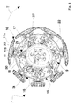
図に示す移送および回転装置7は、複数の保持ヘッド10を備え、詳細には7つの異なる保持ヘッドを備え、それらは、ロータ9の第1の回転軸線R1の周りに径方向に分布している。
The transfer and
2つの連続する保持ヘッド、すなわち移送経路Tに沿って第2の保持ヘッドの下流にある第1の保持ヘッドを考えると、第1の保持ヘッドおよび第2の保持ヘッドは、第2のカムプロファイル14に対するそれぞれの変動機構の相対位置に応じて、離れた位置または近い位置で互いから離間することができることを観察することができる。 Considering two consecutive holding heads, i.e., a first holding head downstream of the second holding head along the transfer path T, the first holding head and the second holding head have a second cam profile. It can be observed that they can be separated from each other at a distant or close position, depending on the relative position of the respective variation mechanism with respect to 14.
各支持ベース37の第1の保護壁42および第2の保護壁43は、ロータ9の第1の回転軸線R1に対して径方向にずらして締め付けられ、それにより、上流側保持ヘッドの第1の保護壁42および下流側保持ヘッドの第2の保護壁43は、2つの連続する保持ヘッドが近い位置にあるときに重ね合わせられる。
The first
これは、図7において特に明白であり、この図では、3つの後続の保持ヘッド10’、10’’および10’’’が示され、それぞれ簡略化のためにそれぞれの頂点で識別され、その最も下流側保持ヘッド10’は、中央保持ヘッド10’’に近い位置にあり、中央保持ヘッド10’’は、最も上流側保持ヘッド10’’’に対して離れた位置にある。
This is particularly evident in FIG. 7, in which three subsequent holding heads 10 ′, 10 ″ and 10 ′ ″ are shown, each identified at a respective vertex for simplicity, The most downstream holding
下流側保持ヘッド10’の第2の保護壁43が、中央保持ヘッド10’’の第1の保護壁42に重ね合わせられるが、中央保持ヘッド10’’の第2の保護壁43は、離れた位置にあり、最も上流の保持ヘッドの保護壁42上には重ね合わせられない。
The second
使用時、モータ23がロータ9を作動させると、移送および回転装置7に嵌合されるすべての保持ヘッド10はすべて同じ距離にあり、各保持ヘッド10の変動機構17の回転ピボット18は、ロータ9の同じ角速度で移動する。しかし、第2の従動子19は移動して、ロータ9の第1の回転軸線R1に対して偏心する前壁22の第2のカムプロファイル14と係合し、そして、変動機構17は、第2のカムプロファイル14に対する第2の従動子19の相対位置に応じて、ロータ9に対する特定の角度で周期的に回転する。ロータ9の回転中、変動機構17の第2の端部17bは、次いで、周期的に前方に移動し、その結果、締め付けピン34によって変動機構17と一体の第1のスライド16も前方に引き寄せる。
In use, when the
その結果、各保持ヘッド10は周期的に加速され、続いて減速される。2つの連続する保持ヘッドを考えると、それらの間の距離は、第1の回転軸線R1の周りのロータ9の回転中に修正することができ、したがって保持ステーション4における2つの連続する保持ヘッド間の距離D1(ピックアップステップ)は、解放ステーション6における2つの連続する保持ヘッド間の距離D2(解放ステップ)とは異なり得る。
As a result, each holding
第1のスライド16のスライドはまた、第1のスライド16自体、支持ベース37および第2のスライド36によって画定されるキャリッジを引き寄せ、キャリッジは、キャリッジと一体的に移動する回転軸41および保持要素11を引き寄せる。回転軸41の一端は、ロータ9の第1の回転軸線R1に対してこれも偏心しているリボリューションボディ24の第1のカムプロファイル12と係合することによってロータ9の回転中に移動する、第1の従動子13に連結されるため、回転軸41の他端に固定された保持要素11は、第1のカムプロファイル12内の第1の従動子13の位置に応じて、第2の回転軸線R2に対して回転する。
The slide of the
第1のカムプロファイル12および第2のカムプロファイル14は、各保持ヘッド10を90°回転させる前に加速できるように成形されている。
The
角度位置のそれぞれの変動機構17を介してロータ9に連結された保持ヘッド10により、またロータ9と一体的に回転する、第1の環状ガイド15に摺動可能に連結された第1のスライド16による保持要素11の支持により、保持ヘッド10は、頑丈な方法で支持され、また安定した動きで駆動されて、物体、すなわち衛生物品の構成要素を移送し回転させる。
A first slide slidably connected to a first
第2のスライド35が摺動する第1の環状ガイド16および第2の環状ガイド36の両方が存在することにより、支持ベース37、第1のスライド16および第2のスライド36によって画定されるキャリッジが、保持要素11が固定されている回転軸41を摺動可能に支持することを可能にして、保持要素11が第2の回転軸線R2の周りを回転する間に保持要素11自体に起こり得る振動を回避することが、加えられる。その結果、通常軽量かつ容易に変形可能な生理用品の構成要素の輸送における安定性が保証される。
The carriage defined by the
第1の環状ガイド16と第2の環状ガイド36との間のリボリューションボディ24の特定の配置、および使用時にオペレータ側に向けられるステータ8の前壁22内の第2のカムプロファイル14の配置により、フォーマット変更が必要な場合に、ピックアップステップおよび解放ステップの簡単な変更が可能になる。その結果、保持要素11を交換してその形状および/またはサイズを変更できるため、保持ヘッド10の数を変えることによって、移送される構成要素のフォーマットを修正することが可能である。第2のカムプロファイル14が得られる前壁22を交換するだけで、前のフォーマットとは異なる加速領域および/または減速領域を決定するなどの難しいセットアップ構成なしに、オペレータが任意の新しい保持ヘッドの運動法則を変えることが可能になる。
The specific arrangement of the
Claims (17)
外側面(25)を有するリボリューションボディ(24)を含むステータ(8)と、
前記ステータ(8)に対して第1の回転軸線(R1)を中心に回転可能であるロータ(9)と、
前記ロータ(9)に連結され、前記ロータ(9)に対して第2の回転軸線(R2)を中心に回転可能である保持要素(11)を含む、前記物体(3)の少なくとも1つの保持ヘッド(10)と、
前記移送経路(T)に沿って配置された少なくとも1つの第1の環状ガイド(15)と
を備え、
前記ステータ(8)は、前記外側面(25)内で実現されている第1のカムプロファイル(12)を含み、前記保持ヘッド(10)は、前記第1のカムプロファイル(12)と共働し、連結されている、対応する第1の従動子(13)を含み、前記第1の従動子(13)は、前記第1のカムプロファイル(12)に対する前記第1の従動子(13)の相対位置に応じて、前記第2の回転軸線(R2)の周りで前記保持要素(11)を回転させるのに適しており、
前記ステータ(8)は、第2のカムプロファイル(14)を含み、
前記保持ヘッド(10)は、前記保持要素(11)を支持し、前記第1の環状ガイド(15)に摺動可能に連結された少なくとも1つの第1のスライド(16)を含み、
前記第1のスライド(16)は、第2の従動子(19)を備えた機構(17)によって前記ロータ(9)に連結され、前記第2の従動子(19)は、前記第2のカムプロファイル(14)に対する前記機構(17)の相対位置に応じて、前記第1の環状ガイド(16)内で前記第1のスライド(16)を摺動させるために前記第2のカムプロファイル(14)に連結されるように適合され、
前記ステータ(8)は、前壁(22)を含み、その上に前記第2のカムプロファイル(14)が実現される、装置において、
前記ロータ(9)が、前記リボリューションボディ(24)と前記前壁(22)との間に介在する環状体(27)を含むことを特徴とする、装置。 Device (7) for transferring and rotating an object (3) from a holding station (4) to a release station (6) along an annular transfer path (T), said object (3) being said holding The station (4) has a first orientation different from the second orientation in the release station (6), the device comprising:
A stator (8) including a revolution body (24) having an outer surface (25);
A rotor (9) rotatable about a first rotational axis (R1) relative to the stator (8);
At least one holding of the object (3) comprising a holding element (11) connected to the rotor (9) and rotatable about a second axis of rotation (R2) relative to the rotor (9) A head (10);
At least one first annular guide (15) arranged along the transfer path (T),
The stator (8) includes a first cam profile (12) realized in the outer surface (25), and the holding head (10) cooperates with the first cam profile (12). And a corresponding first follower (13) coupled to the first follower (13) with respect to the first cam profile (12). Suitable for rotating the holding element (11) about the second rotational axis (R2) according to the relative position of
The stator (8) includes a second cam profile (14),
The holding head (10) includes at least one first slide (16) that supports the holding element (11) and is slidably coupled to the first annular guide (15);
The first slide (16) is connected to the rotor (9) by a mechanism (17) having a second follower (19), and the second follower (19) is connected to the second follower (19). Depending on the relative position of the mechanism (17) with respect to the cam profile (14), the second cam profile (in order to slide the first slide (16) in the first annular guide (16)). 14) adapted to be coupled to
The stator (8) comprises a front wall (22) on which the second cam profile (14) is realized,
An apparatus according to claim 1, characterized in that the rotor (9) comprises an annular body (27) interposed between the revolution body (24) and the front wall (22).
前記機構(17)が、前記ロータ(9)の前記第1の回転軸線(R1)に対する前記保持ヘッド(10)の角度位置を変えるための機構(17)である装置。 The apparatus of claim 1, comprising:
The device in which the mechanism (17) is a mechanism (17) for changing the angular position of the holding head (10) with respect to the first rotation axis (R1) of the rotor (9).
前記機構(17)が、前記ロータ(9)によって支持され、前記ロータ(9)の前記第1の回転軸線(R1)に平行である第3の回転軸線(R3)を有する回転ピボット(18)に対して振動しており、前記機構(17)は、前記第2の従動子(19)を有する第1の端部(17a)と、前記第1のスライド(16)に締め付けられた第2の端部(17b)と、を有する装置。 The apparatus according to claim 1 or 2, comprising:
The mechanism (17) is supported by the rotor (9) and has a rotation pivot (18) having a third rotation axis (R3) parallel to the first rotation axis (R1) of the rotor (9). The mechanism (17) has a first end (17a) having the second follower (19) and a second clamped to the first slide (16). End (17b).
前記第2のカムプロファイル(14)が、前記前壁(22)の溝によって実現される平坦なカムを含む装置。 An apparatus according to any one of claims 1 to 3,
The device wherein the second cam profile (14) comprises a flat cam realized by a groove in the front wall (22).
前記第1の環状ガイド(15)が、前記環状体(27)と前記リボリューションボディ(24)との間に介在する装置。 An apparatus according to any one of claims 1 to 4, comprising:
A device in which the first annular guide (15) is interposed between the annular body (27) and the revolution body (24).
前記第1の環状ガイド(15)が、前記環状体(27)と前記前壁(22)との間に介在する装置。 An apparatus according to any one of claims 1 to 5,
The device in which the first annular guide (15) is interposed between the annular body (27) and the front wall (22).
前記第1の環状ガイド(15)が、互いに対向する2つのそれぞれの転動面(28a;28b)を備えた外縁(28)を含み、前記第1のスライド(16)が、前記移送経路(T)に沿って互いに離間されて配置された第1の対のホイール(29)および第2の対のホイール(30)を含み、前記第1の対のホイール(29)および前記第2の対のホイール(30)は、前記第1のスライド(16)上にあそびを有して装着され、各対(29;30)のホイールは、前記第1の環状ガイド(15)の前記外縁(28)のそれぞれの転動面(28a;28b)に沿ってそれぞれ転動するように同軸に配置される装置。 The device according to any one of claims 1 to 6, comprising:
The first annular guide (15) includes an outer edge (28) with two respective rolling surfaces (28a; 28b) facing each other, and the first slide (16) is connected to the transfer path ( A first pair of wheels (29) and a second pair of wheels (30) spaced apart from each other along T), the first pair of wheels (29) and the second pair The wheels (30) are mounted with play on the first slide (16), and each pair (29; 30) of wheels is mounted on the outer edge (28) of the first annular guide (15). ) Arranged coaxially so as to roll along respective rolling surfaces (28a; 28b).
前記第1の環状ガイド(15)が、前記ロータ(9)の前記第1の回転軸線(R1)に対して、前記外縁(28)よりも小さい距離を有する内縁(31)を含み、前記内縁(31)も、互いに対向する2つのそれぞれの転動面(31a;31b)を備えており、前記第1のスライド(16)は、前記第1のスライド(16)上にあそびを有して装着され、互いに同軸であり、それぞれが前記内縁(31)のそれぞれの転動面(31a;31b)に沿って転動するように配置された、第3の対のホイール(32)を含み、前記第3の対のホイール(32)は、前記移送経路(T)に沿って前記第1の対のホイール(29)と前記第2の対のホイール(30)との間に介在する装置。 The apparatus according to claim 7, comprising:
The first annular guide (15) includes an inner edge (31) having a smaller distance than the outer edge (28) with respect to the first rotation axis (R1) of the rotor (9), and the inner edge (31) also includes two respective rolling surfaces (31a; 31b) facing each other, and the first slide (16) has play on the first slide (16). A third pair of wheels (32) mounted and coaxial with each other, each arranged to roll along a respective rolling surface (31a; 31b) of said inner edge (31); The third pair of wheels (32) is interposed between the first pair of wheels (29) and the second pair of wheels (30) along the transfer path (T).
前記第1のスライド(16)が、前記第1の対のホイール(29)、前記第2の対のホイール(30)および前記第3の対のホイール(32)が締め付けられたブラケット(33)を含み、前記第1の対のホイール(29)および前記第2の対のホイール(30)は、前記ロータ(9)の前記第1の回転軸線(R1)に対して、前記第3の対のホイール(32)よりも外側に締め付けられる装置。 The apparatus according to claim 8, comprising:
The first slide (16) is a bracket (33) to which the first pair of wheels (29), the second pair of wheels (30) and the third pair of wheels (32) are fastened. The first pair of wheels (29) and the second pair of wheels (30) are arranged in the third pair with respect to the first rotational axis (R1) of the rotor (9). Device tightened outside the wheel (32).
前記第1のスライド(16)がまた、それぞれ締め付けピン(34)を含み、前記ピン(34)は、前記ブラケット(33)に締め付けられた第1の端部と、前記機構(17)の端部(17b)に締め付けられた第2の端部と、を有する装置。 The apparatus of claim 9, comprising:
Each of the first slides (16) also includes a clamping pin (34), the pin (34) being a first end clamped to the bracket (33) and an end of the mechanism (17). And a second end fastened to the part (17b).
第2の環状ガイド(35)をさらに備え、前記リボリューションボディ(24)が、前記第1の環状ガイド(15)と前記第2の環状ガイド(35)との間に介在し、前記保持ヘッド(10)はまた、前記保持要素(11)を支持し、前記第2の環状ガイド(35)に摺動可能に連結された、第2のスライド(36)を含む装置。 An apparatus according to any one of claims 1 to 10, comprising:
The holding head is further provided with a second annular guide (35), and the revolving body (24) is interposed between the first annular guide (15) and the second annular guide (35). (10) also includes a second slide (36) supporting the retaining element (11) and slidably coupled to the second annular guide (35).
前記保持ヘッド(10)が、前記第1のスライド(16)および前記第2のスライド(36)がそれぞれ締め付けられた第1の対向する側部(37a)を有する、特に矩形のものである、支持ベース(37)を含み、前記支持ベース(37)は、前記第1の従動子(13)が連結される第1の端部と、前記保持要素(11)が連結される第2の端部と、の間を延びる軸(41)を収容するための穴を有する装置。 The apparatus of claim 11, comprising:
The holding head (10) is in particular rectangular, having first opposing sides (37a) to which the first slide (16) and the second slide (36) are respectively clamped; The support base (37) includes a first end to which the first follower (13) is connected and a second end to which the holding element (11) is connected. And a device for receiving a shaft (41) extending there between.
前記支持ベース(37)と、前記第1のスライド(16)と、前記第2のスライド(36)とが、前記第1の環状ガイド(15)および前記第2の環状ガイド(35)上で摺動可能である前記保持要素(11)の支持キャリッジを画定する装置。 The apparatus according to claim 12, comprising:
The support base (37), the first slide (16), and the second slide (36) are on the first annular guide (15) and the second annular guide (35). Device for defining a support carriage of the holding element (11) that is slidable.
前記保持ヘッド(10)が、前記移送経路(T)に沿って前記支持ベース(37)からそれぞれ下流側および上流側に、前記支持ベース(37)の第2の対向する側部(37b)に締め付けられた第1の保護壁(42)および第2の保護壁(43)を含み、それぞれの保護壁(42;43)は、汚染粒子から前記第1のカムプロファイル(12)を保護するように構成される装置。 14. The device according to claim 13, wherein
The holding head (10) is located downstream and upstream from the support base (37) along the transfer path (T), respectively, on a second opposing side (37b) of the support base (37). It includes a clamped first protective wall (42) and a second protective wall (43), each protective wall (42; 43) protecting the first cam profile (12) from contaminant particles. Device configured to.
第1の保持ヘッド(10’;10’’)が、前記移送経路(T)に沿って第2の保持ヘッド(10’’;10’’’)の下流にある、複数の保持ヘッド(10’;10’’;10’’’)を備え、前記第1の保持ヘッド(10’;10’’)および前記第2の保持ヘッド(10’’;10’’’)は、前記第2のカムプロファイル(14)に対するそれぞれの前記機構(17)の相対位置に応じて、離れた位置または近い位置に互いから離間することができ、各支持ベース(37)の前記第1の保護壁(42)および前記第2の保護壁(43)は、前記ロータ(9)の前記第1の回転軸線(R1)に対して半径方向にずらされて締め付けられ、それにより、前記第1の保持ヘッド(10’;10’’)および前記第2の保持ヘッド(10’’;10’’’)は、前記近い位置にあり、前記第2の保持ヘッド(10’’;10’’’)の前記第1の保護壁(42)および前記第1の保持ヘッド(10’;10’’)の前記第2の保護壁(43)は、互いに重ね合わせられる装置。 15. An apparatus according to claim 14, wherein
A plurality of holding heads (10 ′; 10 ′; 10 ″) are downstream of the second holding head (10 ″; 10 ′ ″) along the transfer path (T). ';10'';10'''), the first holding head (10 ';10'') and the second holding head (10'';10''') Depending on the relative position of the respective mechanism (17) with respect to its cam profile (14), the first protective wall ( 42) and the second protective wall (43) are clamped by being shifted in the radial direction with respect to the first rotation axis (R1) of the rotor (9), whereby the first holding head (10 ′; 10 ″) and the second holding head (10 ″; 10 ′ ″) are in the close position, The first protective wall (42) of the second holding head (10 ''; 10 ''') and the second protective wall (43) of the first holding head (10'; 10 '') Are devices that are superposed on each other.
前記第1の従動子(13)が、第4の回転軸線(R4)に沿って軸方向に延び、前記保持要素(11)の前記第2の回転軸線(R2)および前記第4の回転軸線(R4)が、互いに交差し、また交差点において、前記ロータ(9)の前記第1の回転軸線(R1)にも交差する装置。 An apparatus according to any one of claims 1 to 15, comprising:
The first follower (13) extends in the axial direction along a fourth rotation axis (R4), and the second rotation axis (R2) and the fourth rotation axis of the holding element (11). A device in which (R4) intersects each other and also intersects the first rotation axis (R1) of the rotor (9) at the intersection.
複数の物体(3)、特に衛生用品を実現するための構成部品を、処理経路(P1)に沿って保持ステーション(4)に連続的に供給する処理装置(2)であって、前記物体(3)は第1の配向で前記保持ステーション(4)に配置される、処理装置と、
解放ステーション(6)から前記物体(3)を連続的に受け入れる前進経路(P2)に沿った不透明材料連続ウェブの前進ライン(5)であって、前記物体(3)は、第2の配向で配置された前記解放ステーション(6)内に受け入れられる、前進ラインと
を備え、
前記包装機(1)はまた、請求項1から16のいずれか1つに記載の移送および回転装置(7)を含み、前記移送および回転装置(7)は、前記処理装置(2)の前記保持ステーション(4)から物体(3)を受け入れ、前記物体(3)自体を前記第1の配向から前記第2の配向に回転させることによって移送経路(T)に沿って前記前進ライン(5)の前記解放ステーション(6)に移送するための少なくとも1つの保持ヘッド(10)を含む、包装機。 A packaging machine (1) for manufacturing sanitary products,
A processing device (2) for continuously supplying a plurality of objects (3), in particular components for realizing sanitary goods, to a holding station (4) along a processing path (P1), wherein said objects ( 3) a processing device arranged in the holding station (4) in a first orientation;
An advance line (5) of a continuous web of opaque material along an advance path (P2) that continuously receives the object (3) from a release station (6), the object (3) being in a second orientation A forward line received in the deployed release station (6), and
The packaging machine (1) also includes a transfer and rotation device (7) according to any one of claims 1 to 16, wherein the transfer and rotation device (7) is a part of the processing device (2). The advance line (5) along the transfer path (T) by receiving the object (3) from the holding station (4) and rotating the object (3) itself from the first orientation to the second orientation. A packaging machine comprising at least one holding head (10) for transfer to said release station (6) of the machine.
Applications Claiming Priority (3)
| Application Number | Priority Date | Filing Date | Title |
|---|---|---|---|
| IT102016000087583 | 2016-08-26 | ||
| IT102016000087583A IT201600087583A1 (en) | 2016-08-26 | 2016-08-26 | Equipment for transferring and rotating an object |
| PCT/IB2017/054699 WO2018037304A1 (en) | 2016-08-26 | 2017-08-01 | Apparatus for transferring and rotating an object |
Publications (2)
| Publication Number | Publication Date |
|---|---|
| JP2019528131A true JP2019528131A (en) | 2019-10-10 |
| JP6888080B2 JP6888080B2 (en) | 2021-06-16 |
Family
ID=57610349
Family Applications (1)
| Application Number | Title | Priority Date | Filing Date |
|---|---|---|---|
| JP2019511448A Active JP6888080B2 (en) | 2016-08-26 | 2017-08-01 | A device for transferring and rotating an object |
Country Status (8)
| Country | Link |
|---|---|
| US (1) | US10765562B2 (en) |
| EP (1) | EP3504139A1 (en) |
| JP (1) | JP6888080B2 (en) |
| KR (1) | KR20190039513A (en) |
| CN (1) | CN109641703B (en) |
| BR (1) | BR112019002741A2 (en) |
| IT (1) | IT201600087583A1 (en) |
| WO (1) | WO2018037304A1 (en) |
Cited By (1)
| Publication number | Priority date | Publication date | Assignee | Title |
|---|---|---|---|---|
| JP2023007484A (en) * | 2021-06-28 | 2023-01-18 | ジ ディ エンメ ソシエタ ペル アチオニ | Method and apparatus for depositing discrete element on support element |
Families Citing this family (16)
| Publication number | Priority date | Publication date | Assignee | Title |
|---|---|---|---|---|
| JP6727568B2 (en) * | 2018-10-16 | 2020-07-22 | 上野精機株式会社 | Electronic component transport facility |
| EP3733383B1 (en) | 2019-05-02 | 2022-12-21 | Teepack Spezialmaschinen Gmbh & Co. Kg | Device and method for producing a bag with a wrapper containing a brewable material |
| IT201900007193A1 (en) * | 2019-05-24 | 2020-11-24 | Gd Spa | Conveying system for a bottle filling machine, in particular in the pharmaceutical sector |
| EP3984924A4 (en) * | 2019-06-11 | 2022-08-10 | Zuiko Corporation | DEVICE AND METHOD OF TRANSPORT |
| CN110367987B (en) * | 2019-08-15 | 2021-10-29 | 中国体育国际经济技术合作有限公司 | Physical stamina detects uses device |
| JP7237791B2 (en) | 2019-10-03 | 2023-03-13 | ユニ・チャーム株式会社 | Linear motor type absorbent article material conveying device and absorbent article manufacturing method |
| US11737930B2 (en) | 2020-02-27 | 2023-08-29 | Curt G. Joa, Inc. | Configurable single transfer insert placement method and apparatus |
| IT202000013714A1 (en) * | 2020-06-09 | 2021-12-09 | MACHINE FOR CHANGING PACE AND ORIENTATION OF DISCRETE ITEMS | |
| CN111658322A (en) * | 2020-07-07 | 2020-09-15 | 安庆市恒昌机械制造有限责任公司 | Rotary variable-pitch mechanism for hygienic products |
| CN111973345A (en) * | 2020-08-24 | 2020-11-24 | 福建道普精工机械设备有限公司 | Adjustable variable-pitch flat-bed machine structure of composite core body of infant cheering pants |
| ES3010442T3 (en) | 2020-08-31 | 2025-04-03 | Teepack Spezialmaschinen Gmbh & Co Kg | Device for manufacturing a bag accommodated in an envelope |
| CN112875203B (en) * | 2021-03-25 | 2022-09-20 | 四川兴事发门窗有限责任公司 | Transferring system and transferring method for fireproof door core plate |
| CN113548480B (en) * | 2021-08-12 | 2023-05-12 | 浙江新余宏智能装备有限公司 | Elliptical ring deformation transverse speed changing device and transverse speed changing method thereof |
| NL2029381B1 (en) * | 2021-10-12 | 2023-05-09 | Foodmate Bv | A system and method for transferring poultry legs |
| IT202300008976A1 (en) * | 2023-05-05 | 2024-11-05 | Gdm Spa | METHOD AND DEVICE FOR TREATMENT OF DISCRETE PIECES FOR ABSORBENT ARTICLES |
| CN121559097B (en) * | 2026-01-23 | 2026-03-27 | 速博达(深圳)自动化有限公司 | Rotating mechanism and sample detection device |
Citations (5)
| Publication number | Priority date | Publication date | Assignee | Title |
|---|---|---|---|---|
| JP2010516589A (en) * | 2007-01-17 | 2010-05-20 | ファメッカニカ.データ エス.ピー.エー. | A device that rotates the article by changing the pitch between conveyed articles |
| US20130239765A1 (en) * | 2007-02-21 | 2013-09-19 | Curt G. Joa, Inc. | Single transfer insert placement and apparatus with cross-direction insert placement control |
| WO2014167369A1 (en) * | 2013-04-10 | 2014-10-16 | Inman S.R.L. | Apparatus and process for transferring and rotating an object |
| JP2015514050A (en) * | 2012-04-16 | 2015-05-18 | ザ プロクター アンド ギャンブルカンパニー | Device for transferring separate items |
| WO2015079367A1 (en) * | 2013-11-27 | 2015-06-04 | Gdm S.P.A. | Device and method for treating and applying pieces for making absorbent articles. |
Family Cites Families (16)
| Publication number | Priority date | Publication date | Assignee | Title |
|---|---|---|---|---|
| IT1188972B (en) * | 1980-12-12 | 1988-01-28 | Gd Spa | TRANSFER DEVICE FOR BAR-SHAPED ITEMS |
| IT1147391B (en) * | 1981-07-28 | 1986-11-19 | Sasib Spa | TRANSFER DEVICE FOR ASTIFORM OBJECTS IN PARTICULAR OF CIGARETTES |
| JPH0764424B2 (en) * | 1987-04-08 | 1995-07-12 | オリオン機械工業株式会社 | Work rotation delivery device |
| US5025910A (en) * | 1990-02-02 | 1991-06-25 | Curt G. Joa, Inc. | Rotary pad turner |
| JP4331527B2 (en) * | 2002-08-28 | 2009-09-16 | ユニ・チャーム株式会社 | Crotch folding device and crotch folding method of disposable diaper |
| DE102004020549A1 (en) * | 2004-04-27 | 2005-11-24 | Robert Bosch Gmbh | Assembly to transfer blister strips to a conveyer assembly has first release point for empty blister strips and second release point for empty blister strips |
| DE102005046604A1 (en) * | 2005-09-29 | 2007-04-05 | Robert Bosch Gmbh | Device for handling blister strips |
| ES2922456T3 (en) * | 2007-02-21 | 2022-09-15 | Joa Curt G Inc | Simple transfer insert placement method and apparatus |
| ITBO20070431A1 (en) * | 2007-06-19 | 2008-12-20 | Gdm Spa | MACHINE AND METHOD FOR THE CONSTRUCTION OF ABSORBENT ITEMS. |
| IT1399147B1 (en) * | 2009-03-09 | 2013-04-11 | Gdm Spa | DEVICE AND METHOD FOR THE IMPLEMENTATION OF ABSORBENT PADDING FOR INTIMATE HYGIENIC ITEMS AND PLANT FOR THE IMPLEMENTATION OF INTIMATE HYGIENIC ITEMS INCLUDING THE DEVICE. |
| US8820513B2 (en) * | 2012-04-16 | 2014-09-02 | The Procter & Gamble Company | Methods for transferring discrete articles |
| US9597235B2 (en) * | 2012-05-01 | 2017-03-21 | The Procter & Gamble Company | Methods and apparatuses for rejecting defective absorbent articles from a converting line |
| DK2659869T3 (en) * | 2012-05-02 | 2017-11-06 | Joa Curt G Inc | Device for placing single transfer insert with transverse insert insertion control |
| ITMO20130182A1 (en) | 2013-06-24 | 2014-12-25 | Sacmi | SYSTEM FOR CARRYING OBJECTS |
| KR20180015127A (en) * | 2015-04-09 | 2018-02-12 | 쥐디엠 에스.피.에이. | Manufacturing machine for producing hygienic absorbent products |
| US9511952B1 (en) * | 2015-06-23 | 2016-12-06 | The Procter & Gamble Company | Methods for transferring discrete articles |
-
2016
- 2016-08-26 IT IT102016000087583A patent/IT201600087583A1/en unknown
-
2017
- 2017-08-01 WO PCT/IB2017/054699 patent/WO2018037304A1/en not_active Ceased
- 2017-08-01 US US16/328,499 patent/US10765562B2/en active Active
- 2017-08-01 JP JP2019511448A patent/JP6888080B2/en active Active
- 2017-08-01 EP EP17752496.4A patent/EP3504139A1/en not_active Withdrawn
- 2017-08-01 CN CN201780050471.5A patent/CN109641703B/en not_active Expired - Fee Related
- 2017-08-01 BR BR112019002741-6A patent/BR112019002741A2/en not_active IP Right Cessation
- 2017-08-01 KR KR1020197004057A patent/KR20190039513A/en not_active Withdrawn
Patent Citations (5)
| Publication number | Priority date | Publication date | Assignee | Title |
|---|---|---|---|---|
| JP2010516589A (en) * | 2007-01-17 | 2010-05-20 | ファメッカニカ.データ エス.ピー.エー. | A device that rotates the article by changing the pitch between conveyed articles |
| US20130239765A1 (en) * | 2007-02-21 | 2013-09-19 | Curt G. Joa, Inc. | Single transfer insert placement and apparatus with cross-direction insert placement control |
| JP2015514050A (en) * | 2012-04-16 | 2015-05-18 | ザ プロクター アンド ギャンブルカンパニー | Device for transferring separate items |
| WO2014167369A1 (en) * | 2013-04-10 | 2014-10-16 | Inman S.R.L. | Apparatus and process for transferring and rotating an object |
| WO2015079367A1 (en) * | 2013-11-27 | 2015-06-04 | Gdm S.P.A. | Device and method for treating and applying pieces for making absorbent articles. |
Cited By (1)
| Publication number | Priority date | Publication date | Assignee | Title |
|---|---|---|---|---|
| JP2023007484A (en) * | 2021-06-28 | 2023-01-18 | ジ ディ エンメ ソシエタ ペル アチオニ | Method and apparatus for depositing discrete element on support element |
Also Published As
| Publication number | Publication date |
|---|---|
| IT201600087583A1 (en) | 2018-02-26 |
| BR112019002741A2 (en) | 2019-05-14 |
| JP6888080B2 (en) | 2021-06-16 |
| KR20190039513A (en) | 2019-04-12 |
| EP3504139A1 (en) | 2019-07-03 |
| CN109641703B (en) | 2020-10-13 |
| US20200222248A1 (en) | 2020-07-16 |
| WO2018037304A1 (en) | 2018-03-01 |
| CN109641703A (en) | 2019-04-16 |
| US10765562B2 (en) | 2020-09-08 |
Similar Documents
| Publication | Publication Date | Title |
|---|---|---|
| JP6888080B2 (en) | A device for transferring and rotating an object | |
| US8281918B2 (en) | Unit for transferring products | |
| EP2750999B1 (en) | Machine for making absorbent sanitary articles | |
| US20150166294A1 (en) | Device for processing a web of packaging material | |
| CN104670966A (en) | Device and method for treating and applying pieces for making absorbent articles | |
| JP7161525B2 (en) | Apparatus for applying segments of absorbent articles | |
| JP2023007484A (en) | Method and apparatus for depositing discrete element on support element | |
| JP6008599B2 (en) | Method for producing disposable wearing article | |
| US20200345559A1 (en) | Manufacturing method and manufacturing apparatus for disposable wearable article | |
| JP5514424B2 (en) | Composite sheet manufacturing method and manufacturing apparatus | |
| JP7277583B2 (en) | Conveying device and method | |
| JP7326339B2 (en) | Apparatus for processing and applying pieces for manufacturing absorbent articles | |
| JP7450129B2 (en) | Conveyance device | |
| JP7072525B2 (en) | Units for supplying side flaps of hygienic absorbent articles and methods for resformatting supply units | |
| JP6851184B2 (en) | Goods transfer device | |
| ITTO20130919A1 (en) | DEVICE FOR THE PRODUCTION OF A PLURALITY OF ARTICLES CONVEYED IN A FLOW WITH CONSTANT STEP | |
| HK1191628A (en) | Automatic wireless device message management responsive to end user preferences |
Legal Events
| Date | Code | Title | Description |
|---|---|---|---|
| A621 | Written request for application examination |
Free format text: JAPANESE INTERMEDIATE CODE: A621 Effective date: 20200518 |
|
| A977 | Report on retrieval |
Free format text: JAPANESE INTERMEDIATE CODE: A971007 Effective date: 20210420 |
|
| TRDD | Decision of grant or rejection written | ||
| A01 | Written decision to grant a patent or to grant a registration (utility model) |
Free format text: JAPANESE INTERMEDIATE CODE: A01 Effective date: 20210423 |
|
| A61 | First payment of annual fees (during grant procedure) |
Free format text: JAPANESE INTERMEDIATE CODE: A61 Effective date: 20210519 |
|
| R150 | Certificate of patent or registration of utility model |
Ref document number: 6888080 Country of ref document: JP Free format text: JAPANESE INTERMEDIATE CODE: R150 |
|
| R250 | Receipt of annual fees |
Free format text: JAPANESE INTERMEDIATE CODE: R250 |
|
| R250 | Receipt of annual fees |
Free format text: JAPANESE INTERMEDIATE CODE: R250 |