JP2020002702A - Fixture for panel-like members - Google Patents
Fixture for panel-like members Download PDFInfo
- Publication number
- JP2020002702A JP2020002702A JP2018124824A JP2018124824A JP2020002702A JP 2020002702 A JP2020002702 A JP 2020002702A JP 2018124824 A JP2018124824 A JP 2018124824A JP 2018124824 A JP2018124824 A JP 2018124824A JP 2020002702 A JP2020002702 A JP 2020002702A
- Authority
- JP
- Japan
- Prior art keywords
- panel
- holding
- support member
- fixture
- shaped member
- Prior art date
- Legal status (The legal status is an assumption and is not a legal conclusion. Google has not performed a legal analysis and makes no representation as to the accuracy of the status listed.)
- Pending
Links
Images


Classifications
-
- Y—GENERAL TAGGING OF NEW TECHNOLOGICAL DEVELOPMENTS; GENERAL TAGGING OF CROSS-SECTIONAL TECHNOLOGIES SPANNING OVER SEVERAL SECTIONS OF THE IPC; TECHNICAL SUBJECTS COVERED BY FORMER USPC CROSS-REFERENCE ART COLLECTIONS [XRACs] AND DIGESTS
- Y02—TECHNOLOGIES OR APPLICATIONS FOR MITIGATION OR ADAPTATION AGAINST CLIMATE CHANGE
- Y02B—CLIMATE CHANGE MITIGATION TECHNOLOGIES RELATED TO BUILDINGS, e.g. HOUSING, HOUSE APPLIANCES OR RELATED END-USER APPLICATIONS
- Y02B10/00—Integration of renewable energy sources in buildings
- Y02B10/10—Photovoltaic [PV]
-
- Y—GENERAL TAGGING OF NEW TECHNOLOGICAL DEVELOPMENTS; GENERAL TAGGING OF CROSS-SECTIONAL TECHNOLOGIES SPANNING OVER SEVERAL SECTIONS OF THE IPC; TECHNICAL SUBJECTS COVERED BY FORMER USPC CROSS-REFERENCE ART COLLECTIONS [XRACs] AND DIGESTS
- Y02—TECHNOLOGIES OR APPLICATIONS FOR MITIGATION OR ADAPTATION AGAINST CLIMATE CHANGE
- Y02E—REDUCTION OF GREENHOUSE GAS [GHG] EMISSIONS, RELATED TO ENERGY GENERATION, TRANSMISSION OR DISTRIBUTION
- Y02E10/00—Energy generation through renewable energy sources
- Y02E10/50—Photovoltaic [PV] energy
Landscapes
- Roof Covering Using Slabs Or Stiff Sheets (AREA)
Abstract
【課題】波形の屋根のパネル状部材を固定する固定具であって、パネル状部材の位置の制約を緩和することができるパネル状部材用の固定具を提供する。
【解決手段】パネル状部材用の固定具100は、波形の設置面300の第1方向F1に延びる凸状部310を挟む脚部112を含む少なくとも2つの基部110と、基部110上に設けられた支持部材120と、支持部材120に支持され、パネル状部材10の、第1方向F1における端部を保持可能に構成された保持部材140と、を有する。基部110は、支持部材120を設置面の凸状部310から高さ方向に離間させるよう構成されている。支持部材120は、保持部材140を第1方向に移動可能に支持するよう構成されている。
【選択図】図3The present invention provides a fixture for fixing a panel-shaped member of a corrugated roof, wherein the fixture for a panel-shaped member is capable of relaxing restrictions on the position of the panel-shaped member.
A fixture 100 for a panel-shaped member is provided on at least two bases 110 including legs 112 sandwiching a convex portion 310 extending in a first direction F1 of a corrugated installation surface 300, and provided on the base 110. And a holding member 140 supported by the supporting member 120 and configured to hold an end of the panel-shaped member 10 in the first direction F1. The base 110 is configured to separate the support member 120 in the height direction from the projection 310 on the installation surface. The support member 120 is configured to support the holding member 140 movably in the first direction.
[Selection diagram] FIG.
Description
本発明は、例えば太陽電池モジュールのようなパネル状部材用の固定具に関する。 The present invention relates to a fixture for a panel-shaped member such as a solar cell module.
近年、太陽電池モジュールは、様々な種類の屋根に設置されることがある。太陽電池モジュールは、例えば工場や倉庫などの産業用の建物の屋根に設置される場合もある。このような産業用の建物の屋根に、波形をした折板屋根やスレート屋根が用いられることも多い。このような波形をした折板屋根やスレート屋根は、複数枚の屋根材を含んでおり、各々の屋根材の端部同士が重なるようにして配置されている。屋根材の互いに重なった部分は、一般的には、例えばボルトとナットのような締結具によって互いに締結される。 In recent years, solar cell modules may be installed on various types of roofs. The solar cell module may be installed on the roof of an industrial building such as a factory or a warehouse, for example. Corrugated folded roofs and slate roofs are often used for the roofs of such industrial buildings. Such corrugated folded roofs and slate roofs include a plurality of roofing materials, and are arranged such that ends of the respective roofing materials overlap with each other. The overlapping portions of the roofing material are generally fastened together by fasteners such as bolts and nuts.
下記の特許文献1は、屋根材どうしを互いに締結する締結具を利用して、太陽電池モジュールを屋根材上に固定する方法を開示している。具体的には、スレート屋根上に突出している屋根材の葺設に用いたフックボルトのボルト軸に支持部材を被せ、当該支持部材上にチャンネル材を載置される。太陽電池モジュールの架台はこのチャンネル材に固定される。 Patent Literature 1 below discloses a method of fixing a solar cell module on a roof material using a fastener for fastening the roof materials to each other. Specifically, a support member is put on a bolt shaft of a hook bolt used for laying a roof material projecting on a slate roof, and a channel material is placed on the support member. The base of the solar cell module is fixed to this channel material.
特許文献1に記載されているように、屋根材どうしを互いに締結する締結具を利用して、太陽電池モジュールのようなパネル状部材を屋根材上に固定する場合、締結具の位置に応じてパネル状部材の位置に強い制約が生じる。 As described in Patent Literature 1, when a panel-like member such as a solar cell module is fixed on a roof material using a fastener that fastens roof materials to each other, the position of the fastener depends on the position of the fastener. There are strong restrictions on the position of the panel-like member.
したがって、波形の屋根のパネル状部材を固定する固定具であって、パネル状部材の位置の制約を緩和することができるパネル状部材用の固定具が望まれる。 Therefore, a fixture for fixing a panel-shaped member of a corrugated roof, which is capable of relaxing restrictions on the position of the panel-shaped member, is desired.
一態様に係る固定具は、パネル状部材用の固定具は、波形の設置面の第1方向に延びる凸状部を挟む脚部を含む少なくとも2つの基部と、基部上に設けられた支持部材と、支持部材に支持され、パネル状部材の、第1方向における端部を保持可能に構成された保持部材と、を有する。前記基部は、前記支持部材を前記設置面の前記凸状部から高さ方向に離間させるよう構成されている。前記支持部材は、前記保持部材を前記第1方向に移動可能に支持するよう構成されている。 The fixing device according to one aspect is a fixing device for a panel-like member, wherein the fixing member for the panel-shaped member includes at least two bases including legs that sandwich a convex portion extending in the first direction of the corrugated installation surface, and a support member provided on the base. And a holding member supported by the support member and configured to hold an end of the panel-shaped member in the first direction. The base is configured to separate the support member in the height direction from the convex portion of the installation surface. The support member is configured to support the holding member movably in the first direction.
上記態様によれば、パネル状部材の位置の制約を緩和することができる。 According to the above aspect, restrictions on the position of the panel-shaped member can be eased.
以下、図面を参照して、実施形態について説明する。以下の図面において、同一又は類似の部分には、同一又は類似の符号を付している。ただし、図面は模式的なものであり、各寸法の比率等は現実のものとは異なることがあることに留意すべきである。 Hereinafter, embodiments will be described with reference to the drawings. In the drawings, the same or similar parts are denoted by the same or similar reference numerals. However, it should be noted that the drawings are schematic and ratios of dimensions may be different from actual ones.
(1)第1実施形態
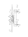
図1は、第1実施形態に係るパネル状部材用の固定具によって設置面に取り付けられたパネル状部材を示す斜視図である。なお、図1は、1つのパネル状部材の端辺が持ち上がられた状態を示していることに留意されたい。図2は、図1の2A−2A線に沿った断面図である。図3は、第1実施形態に係るパネル状部材用の固定具の斜視図である。図4は、図3の4A−4A線に沿った断面図である。図5は、第1実施形態に係るパネル状部材用の固定具の分解斜視図である。
(1) First Embodiment FIG. 1 is a perspective view showing a panel-like member attached to an installation surface by a panel-like member fixing tool according to a first embodiment. It should be noted that FIG. 1 shows a state in which the edge of one panel-shaped member is lifted. FIG. 2 is a sectional view taken along
本実施形態において、パネル状部材の固定構造は、パネル状部材10と、パネル状部材用の固定具100と、を有する。パネル状部材10は固定具100によって設置面300に設置される。設置面300は、図1に示すように波形である。すなわち、設置面300は、第1方向F1に沿って延びる複数の凸状部310を有する。複数の凸状部310は、第1方向F1に交差する第2方向F2に並んでいてよい。そのような設置面300として、例えば波形の折板屋根やスレート屋根が挙げられる。このような設置面300は、設置面300から上方に延びる屋根材締結具によって互いに締結された複数の屋根材を含んでいてよい。
In the present embodiment, the fixing structure of the panel-shaped member includes the panel-
設置面300は、水平面から傾斜していてよい。この場合、傾斜した設置面300において最大傾斜線に沿って高い方から低い方へ向かう方向を「流れ方向」と称する。流れ方向の上流側を「水上側」と称する。流れ方向の下流側を「水下側」と称する。また、水平面に平行な面内で流れ方向F1と直交する方向を「横方向」と称する。なお、本実施形態では、前述した第1方向F1が流れ方向に沿っており、前述した第2方向F2が横方向に沿っている。
The
パネル状部材10は、1つであってもよく、複数の互いに隣接して配置されていてもよい。各々のパネル状部材10は、パネル12と、パネルの端部に取り付けられたフレーム14と、を有していてよい。フレーム14は、パネル12の外周を取り囲んでいてよい。パネル状部材10は、例えば太陽電池モジュールであってよい。この場合、パネル12は、光を電気に変換するための光電変換素子であってよい。
One panel-
固定具100は、基部110と、支持部材120と、回転防止部材130と、保持部材140と、を有していてよい。基部110は、波形の設置面300の第1方向F1に延びる凸状部310を挟む少なくとも2つの脚部112を有していてよい。各々の脚部112は、凸状部310の頂点を挟んで両側の斜面に当接するよう、略逆V字型に傾斜した形状を有していてよい。このように、固定具100は、脚部112によって設置面300に固定されるため、設置面300にもともと備わっている屋根材締結具を利用する場合と比較すると、固定具100の位置に関する制約が緩和される。したがって、パネル状部材10の位置の制約もより緩くなる。
The
また、基部110は、支持部材120を支える上面114と、締結部材180が挿通される孔部119と、を有していてよい。締結部材180は、基部110に形成された孔部119と支持部材120に形成された孔部129とを貫通して、設置面300に達している。これにより、基部110、支持部材120及び設置面300が互いに締結される。
The
防水部材182が、基部110と設置面300の間と、基部110と支持部材120との間の少なくとも一方、好ましくは両方に設けられていてよい。具体的には、基部110と設置面300の間の防水部材182は、一対の脚部112どうしの間で、締結部材180を取り囲むように設けられていてよい。また、基部110と支持部材120との間の防水部材182は、締結部材180を取り囲むように設けられていてよい。孔部129が形成された面は、防水部材182を設置可能なように上面114から凹んだ位置に設けられていてもよい。
The
支持部材120は、基部110上に設けられている。支持部材120は、凸状部310が延びる第1方向Fに沿って延びていてよい。ただし、第1方向Fに沿った支持部材120の長さは、第1方向F1に沿ったパネル状部材10の長さよりも短い。支持部材120は、好ましくは少なくとも2つの基部110、すなわち少なくとも2つの脚部112によって設置面300の凸状部310に固定される。これにより、支持部材120は、安定的に設置面300に固定される。より好ましくは、支持部材120は、2つの基部110、すなわち2つの脚部112によって設置面300の凸状部310に固定される。支持部材120が第1方向F1に短い場合、2つの脚部112であっても十分に支持部材120を安定的に保持することができる。
The
基部110は、支持部材120が、設置面300から上方に延びる前述の屋根材締結具に当接しないように、支持部材120を設置面300の凸状部310から高さ方向に離間させるよう構成されていることが好ましい。これにより、固定具100は、脚部112が当該屋根材締結具に干渉しない限り、設置面300の凸状部310の任意の位置に設置できる。例えば、固定具100は、2つの基部110の間に屋根材締結具が位置するよう設置されてもよい。基部110は、支持部材120が設置面300から上方に延びる前述の屋根材締結具に当接しないように支持部材120を支持しているため、固定具100は設置面300の凸状部310の任意の位置に設置可能である。
The
保持部材140,150は、支持部材120に支持されていてよい。保持部材140,150は、パネル状部材10の第1方向F1に交差する第2方向F2に延びる端部を保持する保持部148,158を有していてよい。本実施形態では、この保持部材は、互いに隣接するパネル状部材のうちの一方のパネル状部材10の端部を保持する保持部148を備えた第1保持部材140と、互いに隣接するパネル状部材のうちの他方のパネル状部材10の端部を保持する保持部158を備えた第2保持部材150と、を有していてよい。第1保持部材140及び第2保持部材150は、高さ方向に延びる締結部材190によって支持部材120に取り付けられていてよい。
The holding
第1保持部材140の保持部148及び第2保持部材150の保持部158は、パネル状部材10の端部の上面、より具体的にはフレーム14の上面を覆うフランジを有していてよい。
The holding
支持部材120は、保持部材140,150を第1方向F1に移動可能に支持するよう構成されていることが好ましい。具体的には、支持部材120は、締結部材190の頭部をスライド可能に保持するスライド構造124を有していてよい。スライド構造124は、第2方向F2において締結部材190の頭部を挟み、板部121から突出する一対の突起を有していてよい。この突起は、第1方向F1に延びており、締結部材190をガイドするレールを構成する。すなわち、このレールは、締結部材190を挟みつつ第1方向F1に締結部材190を移動可能に保持する。これにより、締結部材190の頭部は、一対の突起が延びる第1方向F1に沿って移動可能になる。したがって、第1保持部材140及び第2保持部材150は、締結部材190とともに第1方向F1に沿って移動可能になる。
It is preferable that the
第1保持部材140及び第2保持部材150が第1方向F1に沿って移動可能である場合、パネル状部材10の第1方向F1における設置位置を調節することができる。これにより、前述した屋根材締結具を避けて固定具100を設置する必要がある場合であっても、第1方向F1における第1保持部材140及び第2保持部材150の位置を調節することによって、所望の位置にパネル状部材10を設置することができる。
When the first holding
第1方向F1における第1保持部材140及び第2保持部材150の可動距離は、第1方向における脚部112の長さと、第1方向における屋根材締結具の長さとの和よりも大きいことが好ましい。これにより、屋根材締結具を避けて脚部112を配置したとしても、第1方向F1における第1保持部材140及び第2保持部材150の位置を、任意の位置に設定することができる。
The movable distance of the first holding
第1保持部材140は第1係合部144を有し、第2保持部材150は、第1係合部144に係合する第2係合部154を有していてよい。好ましくは、第2保持部材150は、第1保持部材140に対して第2方向F2に沿った軸まわりに回動可能に構成されている。具体的一例では、第2係合部154は第2方向F2に沿って延びる略円柱状に形成されており、第1係合部144は、第2係合部154を回動可能に嵌合する略円筒形状に形成されている。これにより、第2保持部材150に保持されたパネル状部材10の一端部は、図1に示すように、第2係合部154を軸として持ち上げられるようになる。
The
具体的一例では、第1保持部材140は、横方向F2から見て略Z字状の形状を有していてよい。この場合、Z字状の形状の頂部が第1係合部144を構成していてよい。また、締結部材190は、Z字状の形状の底部のところで第1保持部材140と第2保持部材150を互いに締結していてよい。また、第1係合部144は、Z字状の形状の底部に設けられていてよい。
In a specific example, the first holding
回転防止部材130は、保持部材140,150と、支持部材120との間に設けられる板部131を有していてよい。回転防止部材130は、前述した締結部材190によって保持部材140,150に締結されていてよい。回転防止部材130の板部131は、締結部材190を挿通させる孔部139を有していてよい。
The
本実施形態では、回転防止部材130は、第2保持部材150に保持されたパネル状部材10のフレーム14に引っ掛かる掛かり部134を有していてよい。掛かり部134は、板部131から上方に突出していてよい。掛かり部134は、第2保持部材150のフレーム搭載面152よりも上方に突出しており、フレーム14の内壁に係合するよう構成されている(図2及び図3参照)。これにより、第2保持部材150に保持されたパネル状部材10が掛かり部134に引っ掛かるため、パネル状部材10の抜けを抑制することができる。
In the present embodiment, the
回転防止部材130は、支持部材120の上端部122よりも下方に突出するストッパ132を有していてよい。ストッパ132は、板部131から下方又は斜め下方に延びた部分であってよい。ストッパ132は、第2方向F2における支持部材120の両側に位置することが好ましい。すなわち、ストッパ132は、締結部材190を軸として回転防止部材130が回転しようとしたときに支持部材120の側面に当接する。これにより、ストッパ132は、締結部材190を軸とした回転防止部材130の回転を防止することができる。
The
さらに、第2保持部材150は、締結部材190を軸とした回転方向において、回転防止部材130に係合するよう構成されていてよい。第1実施形態では、横方向F2において回転防止部材130のストッパ132の両側に、第2保持部材150のフレーム搭載面152が位置する。これにより、ストッパ132は、支持部材120に対する保持部材140,150の締結部材190を軸とした回転を防止する機能を有することになる。
Further, the second holding
回転防止部材130は、保持部158を第2方向F2に沿った軸まわりにおける上方へ付勢する弾性部136を有することが好ましい。具体的には、弾性部136は、第2保持部材150を第1保持部材140に対して上方に付勢する。弾性部136は、回転防止部材130の一部に形成された板ばね部によって構成されていてよい。弾性部136は、第2保持部材150を上方に付勢することにより、第2係合部154を中心として第2保持部材150を上方に回動させる。これにより、パネル状部材10が第2保持部材150に保持されていない状態において、図6に示すように、第2保持部材150が斜めに傾くことになる。これにより、パネル状部材10を第2保持部材150に挿入させ易くなる。
Preferably, the
回転防止部材130は、第2方向F2における第2係合部154の両側を覆う被覆部138を有していてよい。これにより、第2保持部材150が第1保持部材140から抜けることを防止することができる。
The
前述した固定具100では、保持部材140,150は、1つの支持部材120あたり、好ましくは少なくとも1つ、より好ましくは1つのみ設けられている。すなわち、保持部材140,150は、複数の支持部材120又は複数の固定具100にわたって延びているわけではない。また、パネル状部材10の互いに対向する2つの端部のそれぞれが、互いに離間して設けられた少なくとも2つの保持部材140,150によって保持されている。すなわち、パネル状部材10は、互いに分離した少なくとも4つの固定具100によって固定される。これにより、パネル状部材10の一辺全体にわたって延びる長尺部材が不要であるため、固定具100全体の重量が低下する。したがって、屋根にかかる負荷を小さくすることができる。
In the
より好ましくは、第2方向F2における保持部材140,150の長さは、互いに隣接する凸状部310どうしのピッチの2倍よりも短い。これにより、保持部材140,150は、固定具100が固定された凸状部310に隣接する凸状部310に上に位置することなく、より固定具100全体の重量を低下させることができる。
More preferably, the length of the holding
次に、前述したパネル状部材用の固定具100を用いたパネル状部材10の設置方法について図6〜図8を参照して以下に説明する。本実施形態に係るパネル状部材10の設置方法では、パネル状部材10は、第1方向F1に延びる凸状部310を有する波形の設置面300に設置される。
Next, a method of installing the panel-shaped
まず、パネル状部材10とパネル状部材用の固定具100を準備する。次に、図6に示すように、締結部材180によって固定具100を設置面300の凸状部310に固定する。このとき、前述したように、第2保持部材150は、弾性部136の作用によって上方に傾斜している。
First, the panel-shaped
次に、第1保持部材140の保持部148にパネル状部材10の端部を保持させる。好ましくは、パネル状部材10は、水上側から保持部148に挿入される(図7参照)。具体的には、固定具100の水上側のパネル状部材10を支持部材120の上端部122上に配置した状態で、保持部材130をスライド構造124に沿って第1方向F1における水上側にスライドさせることによって、保持部材130の保持部148がパネル状部材10の端部を覆った状態になる。次に、第2保持部材150の保持部158にパネル状部材10の端部を保持させる(図8参照)。この際、第2保持部材150が弾性部136の作用によって上方に傾斜しているため、作業員は、パネル状部材10の一端部を掴んだ状態で、保持部158にパネル状部材10の他端部を容易に保持させることができる。
Next, the end of the panel-shaped
それから、作業員は、保持部158に保持させたパネル状部材10の一端部、すなわち掴んだ部分を設置面300に向けて降ろす。これにともない、第2保持部材150は、第2係合部154を軸に回転するため、図2に示すように、設置面300上にパネル状部材10を設置することができる。
Then, the worker lowers one end of the panel-shaped
(2)第2実施形態
次に、第2実施形態に係るパネル状部材の固定構造及びパネル状部材用の固定具について説明する。第2実施形態において、第1実施形態と同様の構成については、同様の符号が付されている。以下では、第1実施形態と同様の構成については、その説明を省略することがある。図9は、第2実施形態に係るパネル状部材用の固定具の側面図である。第2実施形態において、基部110及び支持部材120の構成は、第1実施形態と同様である。
(2) Second Embodiment Next, a panel-shaped member fixing structure and a panel-shaped member fixing device according to a second embodiment will be described. In the second embodiment, the same components as those in the first embodiment are denoted by the same reference numerals. Hereinafter, the description of the same configuration as that of the first embodiment may be omitted. FIG. 9 is a side view of a fixture for a panel-shaped member according to the second embodiment. In the second embodiment, the configurations of the
第2実施形態では、支持部材120に支持される保持部材240は、1つの部材により一体的に形成されている。すなわち、保持部材240は、互いに隣接するパネル状部材10の端部を保持する一対の保持部248,258の両方を有する。
In the second embodiment, the holding
図10は、第2実施形態に係る固定具に備えられた回転防止部材の側面図である。回転防止部材230は、保持部材240と支持部材120との間に設けられている。回転防止部材230は、締結部材190が貫通する孔部239を有する底部237と、底部から起立した起立壁231と、起立壁231から保持部258に沿って曲げられたフランジ235と、を有する。フランジ235は、パネル状部材10の端部の上面を覆うよう構成されている。
FIG. 10 is a side view of a rotation preventing member provided in the fixture according to the second embodiment. The
回転防止部材230は、起立壁231から下方に延びたストッパ232を有していてよい。ストッパ232は、支持部材120の上面よりも下方まで延びている。ストッパ232は、横方向F2における支持部材120の両側に位置していてよい。これにより、ストッパ232は、締結部材190を軸とした回転防止部材130及び保持部材240の回転を防止することができる。
The
図11は、第2実施形態におけるパネル状部材の設置方法における一ステップを示す側面図である。図12は、図11に続くステップを示す側面図である。 FIG. 11 is a side view showing one step in a method for installing a panel-shaped member according to the second embodiment. FIG. 12 is a side view showing a step following FIG. 11.
まず、パネル状部材10とパネル状部材用の固定具100を準備する。次に、締結部材180によって固定具100を設置面300の凸状部310に固定する。次に、保持部材240の保持部258にパネル状部材10の端部を保持させる。本実施形態では、パネル状部材10は、水下側から保持部158に挿入される(図11参照)。次に、保持部材240の保持部248にもう一方のパネル状部材10の端部を保持させる(図12参照)。この際、パネル状部材10の一端部を、保持部材240の保持部248に対向する搭載面152に斜め方向から当てながら、パネル状部材10を押し込んでもよい。これにより、パネル状部材10を設置面300上に設置することができる。
First, the panel-shaped
上述したように、実施形態を通じて本発明の内容を開示したが、この開示の一部をなす論述及び図面は、本発明を限定するものであると理解すべきではない。この開示から当業者には様々な代替の実施形態、実施例及び運用技術が明らかとなる。したがって、本発明の技術的範囲は、上述の説明から妥当な特許請求の範囲に係る発明特定事項によってのみ定められるものである。 As described above, the contents of the present invention have been disclosed through the embodiments. However, it should not be understood that the description and drawings forming a part of the present disclosure limit the present invention. From this disclosure, various alternative embodiments, examples, and operation techniques will be apparent to those skilled in the art. Therefore, the technical scope of the present invention is determined only by the matters specifying the invention according to the claims that are appropriate from the above description.
例えば、第1実施形態では、第2保持部材150のみが、第2方向F2に沿った回転軸まわりに回動可能に構成されている。この代わりに、第1保持部材140と第2保持部材150の両方が、第2方向F2に沿った回転軸まわりに回動可能に構成されていてもよい。
For example, in the first embodiment, only the second holding
また、上記実施形態では、基部110は、支持部材120と別部材によって構成されているが、基部110は支持部材120と一体に構成されていてもよい。
Further, in the above embodiment, the
10 パネル状部材
100 固定具
110 基部
112 脚部
120 支持部材
130 回転防止部材
134 掛かり部
136 弾性部
140 第1保持部材
150 第2保持部材
180 締結部材
182 防水部材
190 締結部材
300 設置面
310 凸状部
F1 第1方向
F2 第2方向
10 Panel-shaped
Claims (8)
波形の設置面の第1方向に延びる凸状部を挟む脚部を含む少なくとも2つの基部と、
前記基部上に設けられた支持部材と、
前記支持部材に支持され、パネル状部材の、前記第1方向における端部を保持可能に構成された保持部材と、を有し、
前記基部は、前記支持部材を前記設置面の前記凸状部から高さ方向に離間させるよう構成されており、
前記支持部材は、前記保持部材を前記第1方向に移動可能に支持するよう構成されている、固定具。 A fixture for a panel-like member,
At least two bases including legs interposing a convex portion extending in the first direction of the corrugated installation surface;
A support member provided on the base,
A holding member supported by the support member and configured to be able to hold an end of the panel-shaped member in the first direction,
The base is configured to separate the support member in the height direction from the convex portion of the installation surface,
The fixing device, wherein the support member is configured to support the holding member movably in the first direction.
前記支持部材は、前記締結部材を挟みつつ前記第1方向に前記締結部材を移動可能に保持するレールを有する、請求項1に記載の固定具。 The holding member is attached to the support member by a fastening member,
The fixture according to claim 1, wherein the support member has a rail that movably holds the fastening member in the first direction while sandwiching the fastening member.
前記保持部は、前記第1方向に交差する第2方向に沿った軸まわりに回動可能に構成されている、請求項1又は2に記載の固定具。 The holding member has a holding portion for holding an end of the panel-shaped member,
The fixing device according to claim 1, wherein the holding portion is configured to be rotatable around an axis along a second direction intersecting the first direction.
前記固定具は、前記支持部材に対する前記保持部材の回転を防止するストッパを有する、請求項1から4のいずれか1項に記載の固定具。 The holding member is attached to the support member by a fastening member,
The fixture according to any one of claims 1 to 4, wherein the fixture has a stopper for preventing rotation of the holding member with respect to the support member.
前記基部は、前記支持部材が前記締結部材に当接しないように、前記支持部材を前記設置面の前記凸状部から高さ方向に離間させるよう構成されている、請求項1から6のいずれか1項に記載の固定具。 The installation surface includes a plurality of roofing materials fastened together by a fastening member extending upward from the installation surface,
The base according to any one of claims 1 to 6, wherein the base is configured to separate the support member in the height direction from the convex portion of the installation surface so that the support member does not contact the fastening member. Or the fixing device according to item 1.
Priority Applications (1)
| Application Number | Priority Date | Filing Date | Title |
|---|---|---|---|
| JP2018124824A JP2020002702A (en) | 2018-06-29 | 2018-06-29 | Fixture for panel-like members |
Applications Claiming Priority (1)
| Application Number | Priority Date | Filing Date | Title |
|---|---|---|---|
| JP2018124824A JP2020002702A (en) | 2018-06-29 | 2018-06-29 | Fixture for panel-like members |
Publications (1)
| Publication Number | Publication Date |
|---|---|
| JP2020002702A true JP2020002702A (en) | 2020-01-09 |
Family
ID=69099374
Family Applications (1)
| Application Number | Title | Priority Date | Filing Date |
|---|---|---|---|
| JP2018124824A Pending JP2020002702A (en) | 2018-06-29 | 2018-06-29 | Fixture for panel-like members |
Country Status (1)
| Country | Link |
|---|---|
| JP (1) | JP2020002702A (en) |
Cited By (1)
| Publication number | Priority date | Publication date | Assignee | Title |
|---|---|---|---|---|
| JP2022165894A (en) * | 2021-04-20 | 2022-11-01 | 株式会社エクソル | MODULE SUPPORT METAL, SOLAR POWER GENERATION EQUIPMENT, AND MODULE CONSTRUCTION METHOD |
Citations (11)
| Publication number | Priority date | Publication date | Assignee | Title |
|---|---|---|---|---|
| JP2010261257A (en) * | 2009-05-11 | 2010-11-18 | Yane Gijutsu Kenkyusho:Kk | Solar cell module fixing structure |
| JP2012017569A (en) * | 2010-07-06 | 2012-01-26 | Douichi Metal Industry Ltd | Fixing component of outdoor structure |
| US20130055662A1 (en) * | 2011-09-02 | 2013-03-07 | Opsun Technologies Inc. | Solar panel securing assembly for sheet metal sloping roofs |
| JP2013087579A (en) * | 2011-10-21 | 2013-05-13 | Daidohant Co Ltd | Fixture device for solar cell module installation apparatus |
| JP2013136892A (en) * | 2011-12-28 | 2013-07-11 | Noritz Corp | Panel fixing device |
| WO2014109194A1 (en) * | 2013-01-11 | 2014-07-17 | 昭和シェル石油株式会社 | Retaining device for solar cell module |
| JP2014163144A (en) * | 2013-02-26 | 2014-09-08 | Ever Kk | Mounting member for solar panel and livestock barn using the same |
| JP2015017451A (en) * | 2013-07-12 | 2015-01-29 | 奥地建産株式会社 | Fixing bracket for roof top article installation |
| JP2016020568A (en) * | 2014-07-14 | 2016-02-04 | 有限会社鴫原コンクリート | Metal fitting for installing solar battery panel, and installation structure of solar panel with use of metal fitting |
| JP2017043963A (en) * | 2015-08-26 | 2017-03-02 | 株式会社かな和工業 | Member and method for mounting solar battery panel |
| JP2017066806A (en) * | 2015-10-01 | 2017-04-06 | シャープ株式会社 | Solar cell module installation structure, installation method, and photovoltaic power generation system using the installation structure |
-
2018
- 2018-06-29 JP JP2018124824A patent/JP2020002702A/en active Pending
Patent Citations (11)
| Publication number | Priority date | Publication date | Assignee | Title |
|---|---|---|---|---|
| JP2010261257A (en) * | 2009-05-11 | 2010-11-18 | Yane Gijutsu Kenkyusho:Kk | Solar cell module fixing structure |
| JP2012017569A (en) * | 2010-07-06 | 2012-01-26 | Douichi Metal Industry Ltd | Fixing component of outdoor structure |
| US20130055662A1 (en) * | 2011-09-02 | 2013-03-07 | Opsun Technologies Inc. | Solar panel securing assembly for sheet metal sloping roofs |
| JP2013087579A (en) * | 2011-10-21 | 2013-05-13 | Daidohant Co Ltd | Fixture device for solar cell module installation apparatus |
| JP2013136892A (en) * | 2011-12-28 | 2013-07-11 | Noritz Corp | Panel fixing device |
| WO2014109194A1 (en) * | 2013-01-11 | 2014-07-17 | 昭和シェル石油株式会社 | Retaining device for solar cell module |
| JP2014163144A (en) * | 2013-02-26 | 2014-09-08 | Ever Kk | Mounting member for solar panel and livestock barn using the same |
| JP2015017451A (en) * | 2013-07-12 | 2015-01-29 | 奥地建産株式会社 | Fixing bracket for roof top article installation |
| JP2016020568A (en) * | 2014-07-14 | 2016-02-04 | 有限会社鴫原コンクリート | Metal fitting for installing solar battery panel, and installation structure of solar panel with use of metal fitting |
| JP2017043963A (en) * | 2015-08-26 | 2017-03-02 | 株式会社かな和工業 | Member and method for mounting solar battery panel |
| JP2017066806A (en) * | 2015-10-01 | 2017-04-06 | シャープ株式会社 | Solar cell module installation structure, installation method, and photovoltaic power generation system using the installation structure |
Cited By (2)
| Publication number | Priority date | Publication date | Assignee | Title |
|---|---|---|---|---|
| JP2022165894A (en) * | 2021-04-20 | 2022-11-01 | 株式会社エクソル | MODULE SUPPORT METAL, SOLAR POWER GENERATION EQUIPMENT, AND MODULE CONSTRUCTION METHOD |
| JP7619631B2 (en) | 2021-04-20 | 2025-01-22 | 株式会社エクソル | Module support bracket, solar power generation equipment, and module installation method |
Similar Documents
| Publication | Publication Date | Title |
|---|---|---|
| US9595911B2 (en) | Tile roof mounting systems | |
| WO2016145419A1 (en) | Sloped roof solar panel mounting system | |
| US10187006B2 (en) | Wedge spring clip mounting system for photovoltaic modules | |
| KR101562909B1 (en) | A structure for mounting a roof panel | |
| US9941835B2 (en) | Manual snap-on photovoltaic mounting system for rapid installation of photovoltaic arrays onto metal roofs | |
| KR101295758B1 (en) | The Mounting Structure and Method for Solar Cell Module | |
| US10298170B2 (en) | Photovoltaic mounting system | |
| US9923509B2 (en) | Spring loaded mounting foot for photovoltaic systems | |
| US8763321B1 (en) | Universal non-penetrating roof solar panel mounting system | |
| WO2012169565A1 (en) | Snow guard for solar cell module, structure for mounting snow guard for solar cell module, and photovoltaic power system | |
| KR101842502B1 (en) | Solar Energy Generation System Fixing Device for Roof | |
| JP4429028B2 (en) | Fixing device | |
| JP2012109573A (en) | Panel type element fastening | |
| JP2020002702A (en) | Fixture for panel-like members | |
| JP3160551U (en) | Roof mount system | |
| JP5313408B1 (en) | Solar cell module mounting device | |
| JP2006120959A (en) | Solar cell module device | |
| JP7498024B2 (en) | Fixture for photovoltaic conversion module | |
| JP7502026B2 (en) | Fixture and panel-like member installation structure | |
| JP2019090165A (en) | Mounting structure for roof-top installation | |
| JP6749798B2 (en) | Fixture for panel array | |
| JP7161311B2 (en) | Panel mounting structures, fixtures for panels, and fixture installation methods | |
| JP2020165280A (en) | Solar power generator | |
| JP2014237966A (en) | On-roof installation object fixing device | |
| JP7299108B2 (en) | Fixture |
Legal Events
| Date | Code | Title | Description |
|---|---|---|---|
| A621 | Written request for application examination |
Free format text: JAPANESE INTERMEDIATE CODE: A621 Effective date: 20210615 |
|
| A977 | Report on retrieval |
Free format text: JAPANESE INTERMEDIATE CODE: A971007 Effective date: 20220513 |
|
| A131 | Notification of reasons for refusal |
Free format text: JAPANESE INTERMEDIATE CODE: A131 Effective date: 20220531 |
|
| A521 | Request for written amendment filed |
Free format text: JAPANESE INTERMEDIATE CODE: A523 Effective date: 20220720 |
|
| A131 | Notification of reasons for refusal |
Free format text: JAPANESE INTERMEDIATE CODE: A131 Effective date: 20220906 |
|
| A601 | Written request for extension of time |
Free format text: JAPANESE INTERMEDIATE CODE: A601 Effective date: 20221028 |
|
| A02 | Decision of refusal |
Free format text: JAPANESE INTERMEDIATE CODE: A02 Effective date: 20230221 |