JP2020002742A - Actuator and vehicle door opening/closing actuator - Google Patents
Actuator and vehicle door opening/closing actuator Download PDFInfo
- Publication number
- JP2020002742A JP2020002742A JP2018125894A JP2018125894A JP2020002742A JP 2020002742 A JP2020002742 A JP 2020002742A JP 2018125894 A JP2018125894 A JP 2018125894A JP 2018125894 A JP2018125894 A JP 2018125894A JP 2020002742 A JP2020002742 A JP 2020002742A
- Authority
- JP
- Japan
- Prior art keywords
- housing
- actuator
- peripheral surface
- inner tube
- regulating member
- Prior art date
- Legal status (The legal status is an assumption and is not a legal conclusion. Google has not performed a legal analysis and makes no representation as to the accuracy of the status listed.)
- Pending
Links
- 230000002093 peripheral effect Effects 0.000 claims abstract description 69
- 230000001105 regulatory effect Effects 0.000 claims description 73
- 230000006835 compression Effects 0.000 claims description 3
- 238000007906 compression Methods 0.000 claims description 3
- 230000009467 reduction Effects 0.000 description 16
- 230000004048 modification Effects 0.000 description 9
- 238000012986 modification Methods 0.000 description 9
- 238000001514 detection method Methods 0.000 description 5
- 230000007246 mechanism Effects 0.000 description 4
- 229910052751 metal Inorganic materials 0.000 description 4
- 239000002184 metal Substances 0.000 description 4
- 239000000758 substrate Substances 0.000 description 3
- XEEYBQQBJWHFJM-UHFFFAOYSA-N Iron Chemical compound [Fe] XEEYBQQBJWHFJM-UHFFFAOYSA-N 0.000 description 2
- 230000004323 axial length Effects 0.000 description 2
- 230000008859 change Effects 0.000 description 2
- 230000008602 contraction Effects 0.000 description 2
- 230000000694 effects Effects 0.000 description 2
- 230000007257 malfunction Effects 0.000 description 2
- 239000000463 material Substances 0.000 description 2
- 239000011347 resin Substances 0.000 description 2
- 229920005989 resin Polymers 0.000 description 2
- BGPVFRJUHWVFKM-UHFFFAOYSA-N N1=C2C=CC=CC2=[N+]([O-])C1(CC1)CCC21N=C1C=CC=CC1=[N+]2[O-] Chemical compound N1=C2C=CC=CC2=[N+]([O-])C1(CC1)CCC21N=C1C=CC=CC1=[N+]2[O-] BGPVFRJUHWVFKM-UHFFFAOYSA-N 0.000 description 1
- 229910052782 aluminium Inorganic materials 0.000 description 1
- XAGFODPZIPBFFR-UHFFFAOYSA-N aluminium Chemical compound [Al] XAGFODPZIPBFFR-UHFFFAOYSA-N 0.000 description 1
- 238000003780 insertion Methods 0.000 description 1
- 230000037431 insertion Effects 0.000 description 1
- 229910052742 iron Inorganic materials 0.000 description 1
- 239000000696 magnetic material Substances 0.000 description 1
- 238000004519 manufacturing process Methods 0.000 description 1
- 239000007769 metal material Substances 0.000 description 1
- 238000000034 method Methods 0.000 description 1
- 230000008569 process Effects 0.000 description 1
Images





Classifications
-
- E—FIXED CONSTRUCTIONS
- E05—LOCKS; KEYS; WINDOW OR DOOR FITTINGS; SAFES
- E05F—DEVICES FOR MOVING WINGS INTO OPEN OR CLOSED POSITION; CHECKS FOR WINGS; WING FITTINGS NOT OTHERWISE PROVIDED FOR, CONCERNED WITH THE FUNCTIONING OF THE WING
- E05F15/00—Power-operated mechanisms for wings
- E05F15/60—Power-operated mechanisms for wings using electrical actuators
- E05F15/603—Power-operated mechanisms for wings using electrical actuators using rotary electromotors
- E05F15/611—Power-operated mechanisms for wings using electrical actuators using rotary electromotors for swinging wings
- E05F15/616—Power-operated mechanisms for wings using electrical actuators using rotary electromotors for swinging wings operated by push-pull mechanisms
- E05F15/622—Power-operated mechanisms for wings using electrical actuators using rotary electromotors for swinging wings operated by push-pull mechanisms using screw-and-nut mechanisms
-
- B—PERFORMING OPERATIONS; TRANSPORTING
- B60—VEHICLES IN GENERAL
- B60J—WINDOWS, WINDSCREENS, NON-FIXED ROOFS, DOORS, OR SIMILAR DEVICES FOR VEHICLES; REMOVABLE EXTERNAL PROTECTIVE COVERINGS SPECIALLY ADAPTED FOR VEHICLES
- B60J5/00—Doors
- B60J5/10—Doors arranged at the vehicle rear
- B60J5/101—Doors arranged at the vehicle rear for non-load transporting vehicles, i.e. family cars including vans
-
- F—MECHANICAL ENGINEERING; LIGHTING; HEATING; WEAPONS; BLASTING
- F16—ENGINEERING ELEMENTS AND UNITS; GENERAL MEASURES FOR PRODUCING AND MAINTAINING EFFECTIVE FUNCTIONING OF MACHINES OR INSTALLATIONS; THERMAL INSULATION IN GENERAL
- F16H—GEARING
- F16H25/00—Gearings comprising primarily only cams, cam-followers and screw-and-nut mechanisms
- F16H25/18—Gearings comprising primarily only cams, cam-followers and screw-and-nut mechanisms for conveying or interconverting oscillating or reciprocating motions
- F16H25/20—Screw mechanisms
-
- F—MECHANICAL ENGINEERING; LIGHTING; HEATING; WEAPONS; BLASTING
- F16—ENGINEERING ELEMENTS AND UNITS; GENERAL MEASURES FOR PRODUCING AND MAINTAINING EFFECTIVE FUNCTIONING OF MACHINES OR INSTALLATIONS; THERMAL INSULATION IN GENERAL
- F16H—GEARING
- F16H25/00—Gearings comprising primarily only cams, cam-followers and screw-and-nut mechanisms
- F16H25/18—Gearings comprising primarily only cams, cam-followers and screw-and-nut mechanisms for conveying or interconverting oscillating or reciprocating motions
- F16H25/20—Screw mechanisms
- F16H25/2015—Means specially adapted for stopping actuators in the end position; Position sensing means
-
- E—FIXED CONSTRUCTIONS
- E05—LOCKS; KEYS; WINDOW OR DOOR FITTINGS; SAFES
- E05Y—INDEXING SCHEME ASSOCIATED WITH SUBCLASSES E05D AND E05F, RELATING TO CONSTRUCTION ELEMENTS, ELECTRIC CONTROL, POWER SUPPLY, POWER SIGNAL OR TRANSMISSION, USER INTERFACES, MOUNTING OR COUPLING, DETAILS, ACCESSORIES, AUXILIARY OPERATIONS NOT OTHERWISE PROVIDED FOR, APPLICATION THEREOF
- E05Y2201/00—Constructional elements; Accessories therefor
- E05Y2201/60—Suspension or transmission members; Accessories therefor
- E05Y2201/622—Suspension or transmission members elements
- E05Y2201/696—Screw mechanisms
- E05Y2201/70—Nuts
-
- E—FIXED CONSTRUCTIONS
- E05—LOCKS; KEYS; WINDOW OR DOOR FITTINGS; SAFES
- E05Y—INDEXING SCHEME ASSOCIATED WITH SUBCLASSES E05D AND E05F, RELATING TO CONSTRUCTION ELEMENTS, ELECTRIC CONTROL, POWER SUPPLY, POWER SIGNAL OR TRANSMISSION, USER INTERFACES, MOUNTING OR COUPLING, DETAILS, ACCESSORIES, AUXILIARY OPERATIONS NOT OTHERWISE PROVIDED FOR, APPLICATION THEREOF
- E05Y2201/00—Constructional elements; Accessories therefor
- E05Y2201/60—Suspension or transmission members; Accessories therefor
- E05Y2201/622—Suspension or transmission members elements
- E05Y2201/71—Toothed gearing
- E05Y2201/72—Planetary gearing
-
- E—FIXED CONSTRUCTIONS
- E05—LOCKS; KEYS; WINDOW OR DOOR FITTINGS; SAFES
- E05Y—INDEXING SCHEME ASSOCIATED WITH SUBCLASSES E05D AND E05F, RELATING TO CONSTRUCTION ELEMENTS, ELECTRIC CONTROL, POWER SUPPLY, POWER SIGNAL OR TRANSMISSION, USER INTERFACES, MOUNTING OR COUPLING, DETAILS, ACCESSORIES, AUXILIARY OPERATIONS NOT OTHERWISE PROVIDED FOR, APPLICATION THEREOF
- E05Y2900/00—Application of doors, windows, wings or fittings thereof
- E05Y2900/50—Application of doors, windows, wings or fittings thereof for vehicles
- E05Y2900/53—Type of wing
- E05Y2900/546—Tailboards, tailgates or sideboards opening upwards
-
- E—FIXED CONSTRUCTIONS
- E05—LOCKS; KEYS; WINDOW OR DOOR FITTINGS; SAFES
- E05Y—INDEXING SCHEME ASSOCIATED WITH SUBCLASSES E05D AND E05F, RELATING TO CONSTRUCTION ELEMENTS, ELECTRIC CONTROL, POWER SUPPLY, POWER SIGNAL OR TRANSMISSION, USER INTERFACES, MOUNTING OR COUPLING, DETAILS, ACCESSORIES, AUXILIARY OPERATIONS NOT OTHERWISE PROVIDED FOR, APPLICATION THEREOF
- E05Y2900/00—Application of doors, windows, wings or fittings thereof
- E05Y2900/50—Application of doors, windows, wings or fittings thereof for vehicles
- E05Y2900/53—Type of wing
- E05Y2900/548—Trunk lids
-
- F—MECHANICAL ENGINEERING; LIGHTING; HEATING; WEAPONS; BLASTING
- F16—ENGINEERING ELEMENTS AND UNITS; GENERAL MEASURES FOR PRODUCING AND MAINTAINING EFFECTIVE FUNCTIONING OF MACHINES OR INSTALLATIONS; THERMAL INSULATION IN GENERAL
- F16H—GEARING
- F16H25/00—Gearings comprising primarily only cams, cam-followers and screw-and-nut mechanisms
- F16H25/18—Gearings comprising primarily only cams, cam-followers and screw-and-nut mechanisms for conveying or interconverting oscillating or reciprocating motions
- F16H25/20—Screw mechanisms
- F16H2025/2062—Arrangements for driving the actuator
- F16H2025/2075—Coaxial drive motors
-
- F—MECHANICAL ENGINEERING; LIGHTING; HEATING; WEAPONS; BLASTING
- F16—ENGINEERING ELEMENTS AND UNITS; GENERAL MEASURES FOR PRODUCING AND MAINTAINING EFFECTIVE FUNCTIONING OF MACHINES OR INSTALLATIONS; THERMAL INSULATION IN GENERAL
- F16H—GEARING
- F16H25/00—Gearings comprising primarily only cams, cam-followers and screw-and-nut mechanisms
- F16H25/18—Gearings comprising primarily only cams, cam-followers and screw-and-nut mechanisms for conveying or interconverting oscillating or reciprocating motions
- F16H25/20—Screw mechanisms
- F16H2025/2062—Arrangements for driving the actuator
- F16H2025/2087—Arrangements for driving the actuator using planetary gears
Landscapes
- Engineering & Computer Science (AREA)
- General Engineering & Computer Science (AREA)
- Mechanical Engineering (AREA)
- Power-Operated Mechanisms For Wings (AREA)
Abstract
Description
本発明は、アクチュエータ及び車両ドア開閉用アクチュエータに関する。 The present invention relates to an actuator and an actuator for opening and closing a vehicle door.
従来から、車両ドア開閉装置として、車体側の開口部の周囲と、この開口部に開閉可能に設けられたテールゲートとの間に、軸方向に伸縮駆動することによってテールゲートを開閉動作させるアクチュエータを設ける構成が知られている(例えば、特許文献1参照)。 2. Description of the Related Art Conventionally, as a vehicle door opening / closing device, an actuator that opens and closes a tailgate by extending and contracting in an axial direction between a periphery of an opening on a vehicle body side and a tailgate provided to be able to open and close the opening. Is known (for example, see Patent Document 1).
特許文献1のアクチュエータは、筒状の第1ハウジングと、第1ハウジングの一端側の内周面に嵌合され、第1ハウジングに出没可能に設けられた第2ハウジングと、を備えている。また、アクチュエータは、第1ハウジングの他端側内に設けられたモータと、モータの回転力を受けて回転駆動する駆動軸(スクリュー軸)と、を備えている。駆動軸は、第1ハウジング及び第2ハウジング内に、軸方向に沿って配置されている。
また、駆動軸は、モータ側の端部が軸受を介して回転自在に支持されている。駆動軸には、従動部(ナット部材)が螺合されている。さらに、従動部は、第2ハウジングの径方向内側に設けられたインナーチューブに固定されており、駆動軸に対して相対回転不能である。
The actuator disclosed in Patent Literature 1 includes a cylindrical first housing, and a second housing fitted to an inner peripheral surface on one end side of the first housing and provided so as to be able to protrude and retract from the first housing. Further, the actuator includes a motor provided inside the other end of the first housing, and a drive shaft (screw shaft) that is driven to rotate by receiving the rotational force of the motor. The drive shaft is disposed in the first housing and the second housing along the axial direction.
The drive shaft is rotatably supported at the motor-side end via a bearing. A driven portion (nut member) is screwed to the drive shaft. Further, the driven portion is fixed to an inner tube provided on the radially inner side of the second housing, and cannot be rotated relative to the drive shaft.
このような構成のもと、駆動軸が回転すると、従動部が駆動軸の軸方向に沿ってスライド移動する。すると、従動部が固定されているインナーチューブ、及びインナーチューブと一体化されている第2ハウジングが、第1ハウジングに対して出没移動する。
このように、従動部とともに第2ハウジング、及びインナーチューブが駆動軸に対してスライド移動するので、駆動軸のモータとは反対側の先端側は、軸受等を介して支持されていない。つまり、駆動軸は、片持ち支持されている。
With such a configuration, when the drive shaft rotates, the driven portion slides along the axial direction of the drive shaft. Then, the inner tube to which the driven portion is fixed, and the second housing integrated with the inner tube move in and out of the first housing.
As described above, the second housing and the inner tube slide with respect to the drive shaft together with the driven portion. Therefore, the distal end side of the drive shaft opposite to the motor is not supported via a bearing or the like. That is, the drive shaft is cantilevered.
ここで、駆動軸が片持ち支持であるので、従動軸の移動に伴う負荷により、軸方向に対して駆動軸が僅かに傾くことがあった。このような場合、インナーチューブに駆動軸の先端部が衝突し、これによって騒音(たたき音)が発生する場合があった。 Here, since the drive shaft is cantilevered, the drive shaft may be slightly inclined with respect to the axial direction due to the load accompanying the movement of the driven shaft. In such a case, the tip of the drive shaft collides with the inner tube, which may generate noise (slap sound).
そこで、本発明は、駆動時の騒音を低減できるアクチュエータ及び車両ドア開閉用アクチュエータを提供する。 Therefore, the present invention provides an actuator that can reduce noise during driving and an actuator for opening and closing a vehicle door.
上記の課題を解決するために、本発明に係るアクチュエータは、筒状の第1ハウジングと、前記第1ハウジングの一端側の内周面に嵌合され、該第1ハウジングに対して出没可能に設けられた筒状の第2ハウジングと、前記第1ハウジングの他端側内に設けられ、回転軸を有するモータと、前記第1ハウジング、及び前記第2ハウジング内に設けられ、前記モータの前記回転軸の回転力を受けて回転駆動する駆動軸と、前記第2ハウジングの径方向内側に設けられたインナーチューブに固定されるとともに前記駆動軸に連係され、該駆動軸の回転にともなって前記駆動軸の軸方向に沿って移動する従動部と、前記駆動軸の前記モータとは反対側の先端部に設けられ、前記従動部の前記駆動軸からの抜けを防止するストッパと、を備え、前記ストッパは、前記駆動軸の軸方向に対する傾きを弾性的に規制する規制部材を備えており、前記規制部材は、前記インナーチューブの内周面に常時摺接されていることを特徴とする。 In order to solve the above-mentioned problem, an actuator according to the present invention is fitted to a cylindrical first housing and an inner peripheral surface on one end side of the first housing, and is capable of protruding and retracting with respect to the first housing. A second cylindrical housing provided; a motor provided inside the other end of the first housing, the motor having a rotating shaft; and the first housing and the second housing provided in the second housing; A drive shaft that is driven to rotate by receiving the rotation force of the rotation shaft, and is fixed to an inner tube provided inside the second housing in the radial direction, is linked to the drive shaft, and rotates with the drive shaft. A driven portion that moves along the axial direction of the drive shaft, and a stopper that is provided at a distal end portion of the drive shaft opposite to the motor and that prevents the driven portion from coming off from the drive shaft; Said Tsu path includes a regulating member for regulating the tilt resiliently with respect to the axial direction of the drive shaft, wherein the regulating member is characterized by being constantly in sliding contact with the inner peripheral surface of the inner tube.
このように、インナーチューブの内周面に、駆動軸の先端部に設けられたストッパの規制部材を常時摺接させることにより、あたかも駆動軸が両持ち支持されている形になり、軸方向に対して駆動軸が傾くことを防止できる。このため、インナーチューブの内周面に駆動軸の先端部が衝突することもなく、アクチュエータ駆動時の騒音を低減できる。
また、規制部材は、駆動軸の傾きを弾性的に規制するので、インナーチューブの内周面と規制部材との間の摺動摩擦抵抗を極力小さくできる。このため、アクチュエータの駆動時の騒音を低減しつつ、モータへの負荷をできる限り小さくできる。
In this way, by constantly bringing the regulating member of the stopper provided at the tip of the drive shaft into sliding contact with the inner peripheral surface of the inner tube, the drive shaft is supported at both ends, as if it were supported in the axial direction. In contrast, the drive shaft can be prevented from tilting. For this reason, the noise at the time of driving the actuator can be reduced without the tip of the drive shaft colliding with the inner peripheral surface of the inner tube.
Further, since the regulating member elastically regulates the inclination of the drive shaft, the sliding friction resistance between the inner peripheral surface of the inner tube and the regulating member can be minimized. For this reason, the load on the motor can be reduced as much as possible while reducing the noise when the actuator is driven.
本発明に係るアクチュエータにおいて、前記規制部材は、前記インナーチューブの前記内周面の全周に渡って摺接されるゴムであることを特徴とする。 In the actuator according to the present invention, the regulating member is made of rubber that is slidably contacted over the entire inner peripheral surface of the inner tube.
このように構成することで、簡素な構造で規制部材によって駆動軸の軸方向に対する傾きを弾性的に規制することができる。また、インナーチューブの内周面の全周に渡ってゴムが摺接されているので、駆動軸の傾き方向に関わらず、駆動軸の傾きを確実に防止することができる。 With this configuration, the inclination of the drive shaft with respect to the axial direction can be elastically regulated by the regulating member with a simple structure. In addition, since the rubber is slid over the entire circumference of the inner peripheral surface of the inner tube, the inclination of the drive shaft can be reliably prevented regardless of the inclination direction of the drive shaft.
本発明に係るアクチュエータは、前記規制部材の外周面に形成された複数の凹部、及び前記規制部材に形成された複数の貫通孔の少なくともいずれか一方を有していることを特徴とする。 The actuator according to the present invention is characterized in that the actuator has at least one of a plurality of concave portions formed on an outer peripheral surface of the regulating member and a plurality of through holes formed in the regulating member.
このように構成することで、ストッパによって、インナーチューブ内の空間を完全に隔ててしまうことがない。つまり、ストッパの凹部又は貫通孔を介し、このストッパによって隔てられた2つの空間内の空気が双方に移動することができる。このため、ストッパによってインナーチューブ内の空気が圧縮されてしまうなどして、アクチュエータの動作不良が生じてしまうことを防止できる。 With this configuration, the space in the inner tube is not completely separated by the stopper. That is, the air in the two spaces separated by the stopper can move to both via the recess or the through hole of the stopper. For this reason, it is possible to prevent the malfunction of the actuator from occurring due to the stopper compressing the air in the inner tube.
本発明に係るアクチュエータにおいて、前記規制部材は、前記駆動軸の前記先端部に固定されている固定部と、前記固定部の周囲を取り囲むように円環状に形成され、前記インナーチューブの前記内周面に摺接される摺接部と、前記固定部と前記摺接部との間に設けられた弾性部材と、を備えていることを特徴とする。 In the actuator according to the aspect of the invention, the regulating member may be formed in a ring shape so as to surround a fixed portion fixed to the distal end portion of the drive shaft and a periphery of the fixed portion, and the inner circumference of the inner tube may be formed. It is characterized by including a sliding contact portion that is in sliding contact with a surface, and an elastic member provided between the fixed portion and the sliding contact portion.
このように構成することで、簡素な構造で、規制部材によって駆動軸の軸方向に対する傾きを弾性的に規制することができる。また、弾性部材の弾性力を調整することより、駆動軸の傾き抑制力を容易に調整できる。このため使い勝手の良い規制部材とすることができる。 With this configuration, the inclination of the drive shaft with respect to the axial direction can be elastically regulated by the regulating member with a simple structure. Further, by adjusting the elastic force of the elastic member, the inclination suppressing force of the drive shaft can be easily adjusted. For this reason, a user-friendly regulating member can be obtained.
本発明に係るアクチュエータにおいて、前記弾性部材は、圧縮コイルばねであることを特徴とする。 In the actuator according to the present invention, the elastic member is a compression coil spring.
このように構成することで、弾性部材の構成を簡素化でき、規制部材の製造コストを低減できる。 With this configuration, the configuration of the elastic member can be simplified, and the manufacturing cost of the regulating member can be reduced.
本発明に係る車両ドア開閉用アクチュエータは、上記に記載のアクチュエータを、開口部に対して開閉可能に設けられたドアを開閉駆動するために用いたことを特徴とする。 An actuator for opening and closing a vehicle door according to the present invention is characterized in that the actuator described above is used for opening and closing a door that is provided to be able to open and close with respect to an opening.
このように構成することで、車両ドア開閉用アクチュエータの駆動時の騒音を低減できる。 With this configuration, it is possible to reduce noise when the vehicle door opening / closing actuator is driven.
本発明によれば、インナーチューブの内周面に、駆動軸の先端部に設けられたストッパの規制部材を常時摺接させることにより、あたかも駆動軸が両持ち支持されている形になり、軸方向に対して駆動軸が傾くことを防止できる。このため、インナーチューブの内周面に駆動軸の先端部が衝突することもなく、アクチュエータ駆動時の騒音を低減できる。 According to the present invention, the regulating member of the stopper provided at the tip of the drive shaft is always slid on the inner peripheral surface of the inner tube, so that the drive shaft is supported at both ends. The inclination of the drive shaft with respect to the direction can be prevented. For this reason, the noise at the time of driving the actuator can be reduced without the tip of the drive shaft colliding with the inner peripheral surface of the inner tube.
次に、本発明の実施形態を図面に基づいて説明する。 Next, an embodiment of the present invention will be described with reference to the drawings.
(第1実施形態)
(車両ドア開閉用アクチュエータ)
図1は、本発明の第1実施形態における車両ドア開閉用アクチュエータ100(以下、単にアクチュエータ100という)を備えた自動車1の例を示す斜視図である。
図1に示すように、アクチュエータ100は、自動車1の例えばテールゲート(ドア)2を開閉する。テールゲート2は、自動車1の車体後部に形成された開口部3の上部3aに、不図示のヒンジ機構を介して開口部3を開閉可能に設けられている。
(1st Embodiment)
(Vehicle door opening / closing actuator)
FIG. 1 is a perspective view illustrating an example of an automobile 1 including a vehicle door opening / closing actuator 100 (hereinafter, simply referred to as an actuator 100) according to the first embodiment of the present invention.
As shown in FIG. 1, the
アクチュエータ100は、開口部3の左右両側又は片側にそれぞれ設けられている。そして、開口部3の外枠部3sに、不図示のボールスタッドを介してアクチュエータ100の一端100aが回動可能に連結されている。また、テールゲート2に、不図示のボールスタッドを介してアクチュエータ100の他端100bが回動可能に連結されている。
なお、以下では、アクチュエータ100の開口部3側を、一端側または一方と称し、テールゲート2側を、他端側、または他方と称して説明する場合がある。
The
Hereinafter, the opening 3 side of the
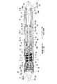
図2は、アクチュエータ100の斜視図である。図3は、アクチュエータ100の軸方向に沿う断面図である。
図2、図3に示すように、アクチュエータ100は、略円筒状の第1ハウジング(請求項における第1ハウジングに相当)6と、第1ハウジング6の他端6b(図2、図3における右側端)の内周面に、一端7a(図2、図3における左側端)が嵌合固定されている略円筒状の第2ハウジング(請求項における第1ハウジングに相当)7と、第2ハウジング7の他端7bの内周面に、出没可能に嵌合されている略円筒状の第3ハウジング(請求項における第2ハウジングに相当)8と、の3つのハウジング6〜8を備えた棒状体である。
FIG. 2 is a perspective view of the
As shown in FIGS. 2 and 3, the
なお、以下の説明では、各ハウジング6〜8の中心軸に沿う方向を単に軸方向と称し、各ハウジング6〜8の径方向を単に径方向と称し、各ハウジング6〜8の外周面に沿う方向を単に周方向と称して説明する。 In the following description, a direction along the central axis of each of the housings 6 to 8 is simply referred to as an axial direction, a radial direction of each of the housings 6 to 8 is simply referred to as a radial direction, and is along an outer peripheral surface of each of the housings 6 to 8. The direction will be described simply as the circumferential direction.
(第1ハウジング)
図4は、アクチュエータ100の一方側(図3の左側)の部分拡大断面図である。
図4に示すように、第1ハウジング6は、例えば鉄等の金属製材料により形成されている。この第1ハウジング6の一端6aに、開口部3の外枠部3s(図1参照)に設けられたボールスタッド(不図示)に連結されるジョイント部9が設けられている。ジョイント部9は、第1ハウジング6の一端6aに内嵌された略円板状のプレート部9aと、プレート部9aから第1ハウジング6の軸方向一方(外方)に突出するソケット部9bと、が一体成形されている。プレート部9aには、後述するハーネスカバー26を挿通可能な不図示の挿通孔が形成されている。
(First housing)
FIG. 4 is a partially enlarged cross-sectional view of one side of the actuator 100 (the left side in FIG. 3).
As shown in FIG. 4, the first housing 6 is formed of a metal material such as iron. At one
また、第1ハウジング6の一端6aには、略円筒状のエンドカバー10が装着されている。エンドカバー10は、第1ハウジング6の一端6aの外周面に嵌合固定されている。また、エンドカバー10は、ジョイント部9におけるプレート部9aの外周面に嵌合固定されている。これにより、第1ハウジング6の一端6aからジョイント部9が脱落してしまうことを防止できる。
A substantially
(モータ部)
第1ハウジング6には、モータ部11が収納されている。
モータ部11は、略円筒状のヨーク12と、ヨーク12の内周面に固定されているマグネット5と、ヨーク12の径方向内側に回転自在に設けられたアーマチュア13と、アーマチュア13に給電を行うブラシホルダユニット16と、を備えている。ヨーク12は、導電性を有する金属により形成されている。ヨーク12の外径は、第1ハウジング6の内径よりも所定寸法小さく設定されている。
(Motor part)
The
The
ヨーク12の径方向内側に設けられたアーマチュア13は、ヨーク12内で回転可能となるように設けられたシャフト14と、シャフト14に外嵌固定され、磁性材からなるアーマチュアコア15と、アーマチュアコア15に巻回されているコイル20と、シャフト14にアーマチュアコア15と隣接して外嵌固定され、コイル20の端末部が接続されるコンミテータ17と、を備えている。
An
シャフト14は、ヨーク12の径方向中心で軸方向に沿って延びている。そして、シャフト14は、一端がブラシホルダユニット16に挿通されてこのブラシホルダユニット16に回転自在に支持されている。また、シャフト14は、他端が後述の減速ギヤ部27に連結されている。また、シャフト14の一端には、センサマグネット21が取り付けられている。センサマグネット21は、シャフト14の回転位置を検出するための回転位置検出装置23の一方を構成している。
The
アーマチュア13に給電を行うブラシホルダユニット16は、ヨーク12の一端12aにカシメ固定されている樹脂製のブラシホルダ18と、ブラシホルダ18に保持されているブラシ19と、を備えている。このブラシ19が、コンミテータ17に摺接されている。また、ブラシ19は、不図示のハーネスを介して外部電源(例えば、バッテリ)と電気的に接続されている。これにより、外部電源の電力が、ブラシ19、コンミテータ17を介してコイル20に供給される。
The
また、ブラシホルダ18には、シャフト14に設けられたセンサマグネット21の外周面と径方向でするように、不図示のセンサ基板が設けられている。センサ基板は、回転位置検出装置23の他方を構成している。センサ基板には、センサマグネット21の外周面の磁気変化を検出する不図示の磁気検出素子が実装されている。この結果、回転位置検出装置23によって、シャフト14の回転位置を検出できる。
Further, a sensor substrate (not shown) is provided on the
ブラシホルダユニット16のジョイント部9側には、シール部24が装着されている。シール部24は、弾性を有したゴム系材料により形成されている。シール部24は、ブラシホルダユニット16をジョイント部9側から覆うように略有底筒状に形成されたシール本体25を有している。すなわち、シール本体25は、ブラシホルダ18とジョイント部9のプレート部9aとにより挟持された底部25aと、底部25aの外周縁からジョイント部9とは反対側に延び、ブラシホルダユニット16と第1ハウジング6の内周面との間に介在される略円筒状の周壁部25bと、により構成されている。
A
シール本体25の底部25aには、ハーネスカバー26が軸方向一方(外方)に向かって突出形成されている。ハーネスカバー26は、略パイプ状に形成されており、シール本体25の内外を連通している。このように構成されたハーネスカバー26内に、不図示の外部電源とブラシ19とを電気的に接続するための不図示のハーネスが挿通される。
A
このような構成のもと、外部電源の電力が、不図示のハーネス、ブラシ19、及びコンミテータ17を介してコイル20に供給されると、アーマチュアコア15に磁界が形成される。そして、この磁界とヨーク12に固定されたマグネットとの間に生じる磁気的な吸引力や反発力によって、シャフト14がその中心軸回りに回転駆動する。また、シャフト14と一体となってセンサマグネット21が回転する。このセンサマグネット21が回転した際の磁気変化を回転位置検出装置23によって検出し、シャフト14の回転位置が検出される。
With such a configuration, when the power of the external power supply is supplied to the
(減速ギヤ部)
シャフト14の他端に連結されている減速ギヤ部27は、第1段遊星ギヤ部35と、第2段遊星ギヤ部36と、を有する2段遊星減速機構として構成されている。そして、減速ギヤ部27は、シャフト14の回転を、第1段遊星ギヤ部35と第2段遊星ギヤ部36とにより2段で減速して出力する。減速ギヤ部27の出力は、第2段遊星ギヤ部36に連結されているスクリュー軸38に伝達される。
(Reduction gear)
The
スクリュー軸38は、モータ部11におけるシャフト14の中心軸回りに回転駆動する。スクリュー軸38の減速ギヤ部27側の一端38aは、軸受ホルダ39に回転自在に支持されている。また、第1ハウジング6の減速ギヤ部27側の他端6bは、軸受ホルダ39よりも他方(図4における右方)に向かって突出している。
The
軸受ホルダ39は、略円環状に形成されており、第1ハウジング6の減速ギヤ部27よりも他端側(図4における右側)の内周面に嵌合され、かしめ固定されている。このような軸受ホルダ39の内周面に、軸受40が挿入、または圧入されている。この軸受40を介し、軸受ホルダ39がスクリュー軸38の一端38aを回転自在に支持している。
また、軸受ホルダ39の減速ギヤ部27側の端面には、径方向中央の大部分に凹部39bが形成されている。この凹部39bに、減速ギヤ部27の他端側が挿入されている。
The bearing
In addition, a
スクリュー軸38は、軸受ホルダ39から軸方向他方に向かって突出するように延出されている。スクリュー軸38は、いわゆる台形ネジであって、外周面にネジ条が形成されている。このように構成されたスクリュー軸38の周囲を覆うように、第2ハウジング7が設けられている。
The
(第2ハウジング)
図3、図4に示すように、第2ハウジング7は、樹脂材料等により形成されている。第2ハウジング7の外径は、第1ハウジング6の他端6bに嵌合されている一端7a側を除いて、第1ハウジング6の外径とほぼ同一に設定されている。第2ハウジング7の一端7a側は、段差により縮径形成されて縮径部7cとされている。この縮径部7cが、第1ハウジング6の他端6bに圧入されて固定されている。これにより、第1ハウジング6の外周面と第2ハウジング7の外周面とがほぼ面一の状態で、第1ハウジング6と第2ハウジング7とが一体化される。
(Second housing)
As shown in FIGS. 3 and 4, the
また、第2ハウジング7は、この第2ハウジング7の一端7a側を第1ハウジング6の他端6bに嵌合固定させた状態で、スクリュー軸38の他端(先端部)38bよりも第2ハウジング7の他端7bが若干突出するように形成されている。さらに、第2ハウジング7の縮径部7cの長さは、第1ハウジング6の他端6bに圧入した際、軸受ホルダ39に縮径部7cが当接されない長さに設定されている。
第2ハウジング7の一端7aには、径方向内側に曲折させてなる内フランジ46が形成されている。この内フランジ46には、後述するコイルスプリング47の一端が当接される。
Further, the
At one
第2ハウジング7には、この第2ハウジング7の内周面に沿うように螺旋状に形成されたコイルスプリング47が設けられている。このコイルスプリング47の一端が、第2ハウジング7の内フランジ46に当接されている。また、コイルスプリング47の自由長は、第2ハウジング7の長さよりも十分長く設定されている。このため、第2ハウジング7の内フランジ46にコイルスプリング47の一端を当接させた状態で、コイルスプリング47の他端が、第2ハウジング7の他端7bから突出している。
The
(第3ハウジング)
第2ハウジング7の他端7bに出没可能に設けられた略円筒状の第3ハウジング8は、その外径が第2ハウジング7の外径よりも若干小さく設定されている。そして、第2ハウジング7の他端7bに、第3ハウジング8のモータ部11側の一端8a側が挿入されている。これにより、第2ハウジング7の他端7bから、第3ハウジング8が出没可能になる。そして、第3ハウジング8にコイルスプリング47の他端側が収納される。
第3ハウジング8の他端8bには、径方向内側に曲折させてなる内フランジ53が形成されている。この内フランジ53には、内面側にコイルスプリング47の他端が当接されるとともに、外面側にジョイント部54が当接される。
(3rd housing)
The outer diameter of the substantially cylindrical
The
ジョイント部54は、テールゲート2(図1参照)に設けられたボールスタッド(不図示)に連結される。ジョイント部54は、第3ハウジング8の内フランジ53に当接する略円板状のプレート部54aと、プレート部54aから軸方向他方(外方)に突出するソケット部54bと、が一体成形されている。
The
プレート部54aの外径は、第3ハウジング8の外径よりも若干小さい程度に設定されている。また、プレート部54aの径方向略中央には、第3ハウジング8の内フランジ53を介して第3ハウジング8内に突出する略円柱状の固定凸部55が一体成形されている。固定凸部55の軸方向略中央には、全周に渡って係合溝55aが形成されている。このように構成された固定凸部55に、インナーチューブ56の他端56bが固定されている。
The outer diameter of the
(インナーチューブ)
第3ハウジング8は、この第3ハウジング8の径方向内側に配置された略円筒状のインナーチューブ56を備えている。インナーチューブ56は、例えばアルミに引き抜き加工を施して形成されている。インナーチューブ56の他端56bの外周面は、第3ハウジング8の内フランジ53の内周面に嵌合されている。インナーチューブ56と第3ハウジング8との間に形成された空間に、コイルスプリング47の他端側が収納される。
また、インナーチューブ56の他端56bの内周面に、ジョイント部54の固定凸部55の外周面が嵌合されている。インナーチューブ56の他端56bには、固定凸部55の係合溝55aに嵌る係合凸部71が全周に渡って形成されている。これにより、固定凸部55にインナーチューブ56の他端56bが固定される。
(Inner tube)
The
Further, the outer peripheral surface of the fixed
インナーチューブ56の軸方向の長さは、第3ハウジング8の軸方向の長さよりもやや長く設定されている。このため、インナーチューブ56の一端56aは、第3ハウジング8の一端8aを介して第2ハウジング7内に臨まされている。
インナーチューブ56の一端56aには、径方向内側に曲折させてなる内フランジ72が形成されている。この内フランジ72の径方向内側に、スクリュー軸38が挿通されている。また、インナーチューブ56の内周面には、内フランジ72の内側(他方側)に、ナット部材58が固定されている。
The axial length of the
At one
ナット部材58は、このナット部材58の軸方向両側に配置されたインナーチューブ56の内周面に固定された2つの止め輪73a,73bによって、軸方向への移動が規制されている。これにより、インナーチューブ56に、ナット部材58が固定される。ナット部材58には、スクリュー軸38の他端38b側が螺合されている。
The movement of the
ここで、ナット部材58は、インナーチューブ56に固定されており、さらに、インナーチューブ56は、ジョイント部54に固定されている。ジョイント部54は、テールゲート2(図1参照)に設けられたボールスタッド(不図示)に連結される。このため、スクリュー軸38を回転させたとき、ナット部材58がスクリュー軸38と共回りすることがない。このため、スクリュー軸38を回転させると、ナット部材58がスクリュー軸38に沿って移動する。
Here, the
(ストッパ)
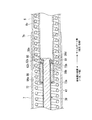
図5は、アクチュエータ100の他方側(図3の右側)の部分拡大断面図である。
図5に示すように、スクリュー軸38の他端38bには、座屈変形させた外フランジ部38cが形成されている。スクリュー軸38の他端38bにおいて、外フランジ部37cが形成されている手前は、台形ネジが形成されていない断面略円形状の取付部38dとされている。この取付部38dに、ストッパ60が設けられている。ストッパ60は、スクリュー軸38からのナット部材58の抜けを防止する役割を有するとともに、スクリュー軸38が軸方向に対して傾くのを防止する役割を有している。
(Stopper)
FIG. 5 is a partially enlarged cross-sectional view of the other side of the actuator 100 (the right side in FIG. 3).
As shown in FIG. 5, a buckling-deformed
ストッパ60は、スクリュー軸38の外周面に嵌合されている略円環状で、弾性変形可能なゴム製の規制部材61と、規制部材61の軸方向両側に配置され、スクリュー軸38に取り付けられている2つの止め輪62a,62bと、を備えている。
The
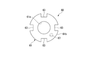
図6は、規制部材61を軸方向からみた平面図である。
図5、図6に示すように、規制部材61の外径は、インナーチューブ56の内径とほぼ同一に設定されている。一方、規制部材61の径方向中央に形成され、スクリュー軸38が挿通される貫通孔61aの直径は、スクリュー軸38の取付部38dの外径とほぼ同一に設定されている。また、規制部材61の外周面61bには、複数(本第1実施形態)の凹部63が形成されている。凹部63は、周方向に等間隔で配置されている。また、凹部63は、軸方向からみて略矩形状に形成されている。すなわち、凹部63は、底辺63aと、底辺63aの周方向両端に配置され、周方向で対向する2つの内側辺63bと、を有している。凹部63が形成されることにより、規制部材61によって隔てられたインナーチューブ56内の2つの空間K1,K2(図7参照)が凹部63を介して連通される。
FIG. 6 is a plan view of the regulating
As shown in FIGS. 5 and 6, the outer diameter of the regulating
ここで、第3ハウジング8の長さは、スクリュー軸38の最も他端38b側にナット部材58が位置している状態で、内フランジ53によってコイルスプリング47を若干圧縮する程度の長さに設定されている。つまり、コイルスプリング47は、常に第3ハウジング8を第2ハウジング7から突出させる方向に向かって付勢している。
また、第3ハウジング8は、インナーチューブ56及びナット部材58を介してスクリュー軸38に連結されており、第2ハウジング7から突出する方向への移動が規制されている。このため、コイルスプリング47は、常に第2ハウジング7の内フランジ46をモータ部11側に向かって付勢している。
Here, the length of the
Further, the
(車両ドア開閉用アクチュエータの動作)
次に、アクチュエータ100の動作について説明する。
操作者の操作によって、不図示の外部電源の電力がモータ部11に供給され、モータ部11のシャフト14を回転駆動させると、シャフト14が回転する。さらに、シャフト14の回転が減速ギヤ部27によって減速されてスクリュー軸38に伝達される。
スクリュー軸38が回転すると、このスクリュー軸38に沿ってナット部材58がスライド移動する。ナット部材58は、第3ハウジング8が備えるインナーチューブ56に固定されているので、これによって、第2ハウジング7に対して第3ハウジング8が出没し、アクチュエータ100が伸縮する。
(Operation of the vehicle door opening / closing actuator)
Next, the operation of the
When an electric power of an external power supply (not shown) is supplied to the
When the
第2ハウジング7に対して第3ハウジング8が没入すると、自動車1の開口部3に設けられたテールゲート2(図1参照)が閉じられる。一方、第2ハウジング7に対して第3ハウジング8が突出すると、自動車1の開口部3に設けられたテールゲート2が開けられる。このとき、アクチュエータ100を伸ばした状態でモータ部11の動作を停止させても、コイルスプリング70の付勢力によって、第2ハウジング7に対し第3ハウジング8の突出した状態が維持される。
When the
(ストッパの作用)
次に、ストッパ60の作用について説明する。
ストッパ60は、スクリュー軸38に形成されている外フランジ部38cと、2つの止め輪62a,62bのうちの外フランジ部38c側に配置された止め輪62aと、で協働して、スクリュー軸38からの規制部材61の抜けを確実に防止できる。この結果、スクリュー軸38からナット部材58の抜けを確実に防止できる。
(Operation of stopper)
Next, the operation of the
The
また、ストッパ60を構成する規制部材61の外径は、インナーチューブ56の内径とほぼ同一に設定されている。一方、規制部材61の径方向中央に形成され、スクリュー軸38が挿通される貫通孔61aの直径は、スクリュー軸38の取付部38dの外径とほぼ同一に設定されている。このため、インナーチューブ56に対して規制部材61が径方向にがたつくことがない。また、規制部材61に対してスクリュー軸38の他端38bが、径方向にがたつくことがない。さらに、規制部材61は、弾性変形可能なゴムにより形成されている。つまり、規制部材61によって、スクリュー軸38の軸方向に対する傾きが弾性的に規制されている。
Further, the outer diameter of the regulating
また、規制部材61は、外径がインナーチューブ56の内径とほぼ同一になるように形成されていることから、スクリュー軸38に沿ってナット部材58がスライド移動することに伴い、インナーチューブ56の内周面と常時摺接することになる。規制部材61は、弾性変形可能なゴムにより形成されているので、インナーチューブ56の内周面と規制部材61の外周面61bとの間の摺動摩擦抵抗が極力小さくなる。
Further, since the regulating
図7は、アクチュエータ100の伸縮動作の途中の状態を示す軸方向に沿う断面図である。
ここで、図7に示すように、アクチュエータ100の伸縮動作の途中では、インナーチューブ56の内部空間が、規制部材61によって2つの空間K1,K2に隔てられる。規制部材61は、外径がインナーチューブ56の内径とほぼ同一になるように形成されているので、仮に規制部材61に凹部63が形成されていないとした場合、ナット部材58(インナーチューブ56)のスライド移動に伴って、空間K1,K2のいずれかが圧縮されることになってしまう。
FIG. 7 is a cross-sectional view along the axial direction showing a state in the middle of the expansion and contraction operation of the
Here, as shown in FIG. 7, during the expansion and contraction operation of the
しかしながら、本第1実施形態では、規制部材61の外周面61bに、複数の凹部63が形成されている。このため、規制部材61によって隔てられたインナーチューブ56内の2つの空間K1,K2が凹部63を介して連通される。よって、ナット部材58(インナーチューブ56)のスライド移動に伴って、空間K1,K2のいずれかが圧縮され、アクチュエータ100の動作に不具合が生じてしまうことを防止できる。
However, in the first embodiment, a plurality of
このように、上述の第1実施形態では、スクリュー軸38からのナット部材58の抜けを防止するためのストッパ60に、ゴム製の規制部材61を設けた。規制部材61の外周面61bは、インナーチューブ56の内周面に常時摺接されている。このため、軸受40とストッパ60とにより、あたかもスクリュー軸38が両持ち支持されている形になる。したがって、簡素な構造でスクリュー軸38が軸方向に対して傾いてしまうことを防止できる。よって、インナーチューブ56の内周面に、スクリュー軸38の他端38bが衝突することもなく、アクチュエータ100の駆動時の騒音を低減できる。
また、規制部材61は、スクリュー軸38の傾きを弾性的に規制するので、インナーチューブ56の内周面と規制部材61との間の摺動摩擦抵抗を極力小さくできる。このため、簡素な構造でアクチュエータ100の駆動時の騒音を低減しつつ、モータ部11への負荷をできる限り小さくできる。
As described above, in the first embodiment described above, the
Further, since the regulating
しかも、規制部材61を略円環状に形成し、凹部63を除く外周面61bの全体がインナーチューブ56の内周面に摺接されている。このため、スクリュー軸38の傾き方向に関わらず、スクリュー軸38の傾きを確実に防止することができる。
また、規制部材61の外周面61bには、複数の凹部63が形成されている。このため、ストッパ60(規制部材61)によって、インナーチューブ56内の空間を完全に隔ててしまうことがない。このため、ストッパ60によってインナーチューブ56内の空気が圧縮されてしまうなどして、アクチュエータ100の動作不良が生じてしまうことを防止できる。
In addition, the regulating
Further, a plurality of
なお、上述の第1実施形態では、規制部材61は、凹部63を除く外周面61bの全体がインナーチューブ56の内周面に摺接されている場合について説明した。しかしながら、これに限られるものではなく、規制部材61の外周面61bのうち、少なくとも一部がインナーチューブ56の内周面に常時摺接されていればよい。このように構成することで、スクリュー軸38の軸方向に対する傾き方向が常に一定である場合、アクチュエータ100の駆動時の騒音を低減できる。
In the first embodiment described above, the case where the entire outer
(第1実施形態の変形例)
また、上述の第1実施形態では、規制部材61は、弾性変形可能なゴム製である場合について説明した。しかしながら、これに限られるものではなく、規制部材61を、以下のように構成してもよい。
(Modification of First Embodiment)
In the first embodiment described above, the case where the regulating
図8は、第1実施形態の変形例における規制部材61を軸方向からみた平面図である。
図8に示すように、規制部材61は、金属製のストッパ本体64の外周面64aに設けられた複数(本変形例では4つ)の弾性変形可能なゴム製の凸部65と、が一体成形されたものである。
ストッパ本体64は略円環状に形成されており、スクリュー軸38の取付部38dの外周面に嵌合固定されている。
FIG. 8 is a plan view of the regulating
As shown in FIG. 8, the regulating
The
凸部65は、ストッパ本体64の外周面64aに沿って軸方向からみて円弧状に形成されている。また、各凸部65は、周方向に等間隔で配置されている。このため、規制部材61の全体としては、周方向に隣接する凸部65間に、複数(本変形例では4つ)の凹部66が形成された形になる。
さらに、凸部65は、径方向外側の先端面65aが常時インナーチューブ56の内周面に摺接する大きさに形成されている。
したがって、上述の変形例によれば、前述の第1実施形態と同様の効果を奏することができる。
The
Further, the
Therefore, according to the above-described modification, the same effects as those of the above-described first embodiment can be obtained.
なお、上述の第1実施形態の変形例では、凸部65が周方向に等間隔で配置されている場合について説明した。しかしながら、これに限られるものではなく、少なくともストッパ本体64の外周面64aの一部に、凸部65が設けられていればよい。このように構成することで、スクリュー軸38の軸方向に対する傾き方向が常に一定である場合、アクチュエータ100の駆動時の騒音を低減できる。
In the modification of the first embodiment described above, the case where the
また、上述の第1実施形態、及び第1実施形態の変形例では、規制部材61に凹部63,66を形成した場合について説明した。しかしながら、これに限られるものではなく、規制部材61に厚さ方向に貫通する貫通孔(例えば、図6に2点鎖線で示す貫通孔67)を形成してもよい。さらに、この貫通孔と凹部63,66との両者を形成してもよい。すなわち、規制部材61は、この規制部材61によって隔てられるインナーチューブ56内の2つの空間K1,K2を連通可能なように、かつ、常時インナーチューブ56の内周面に摺接可能に形成されていればよい。
In the above-described first embodiment and the modification of the first embodiment, the case where the
また、上述の第1実施形態、及び第1実施形態の変形例では、規制部材61に4つの凹部63,66を形成した場合について説明した。しかしながら、これに限られるものではなく、凹部63,66の個数を任意に設定することが可能である。
In the above-described first embodiment and the modifications of the first embodiment, the case where the four
(第2実施形態)
次に、図3、図5を援用し、図9に基づいて、第2実施形態について説明する。
ここで、第1実施形態と第2実施形態との相違点は、第1実施形態のストッパ60における規制部材61と、第2実施形態のストッパ260における規制部材261との構成が異なる点のみである。このため、以下の説明では、第2実施形態の規制部材261についてのみ説明し、その他の構成についての説明を省略する。
(2nd Embodiment)
Next, a second embodiment will be described with reference to FIGS. 3 and 5 and FIG.
Here, the only difference between the first embodiment and the second embodiment is that the configuration of the regulating
図9は、第2実施形態の規制部材261を軸方向からみた平面図である。
図9に示すように、規制部材261は、スクリュー軸38の取付部38dの外周面に嵌合固定される略円環状の固定部81と、固定部81の周囲を取り囲むように略円環状に形成され、インナーチューブ56の内周面に摺接される摺接部82と、固定部81と摺接部82との間に設けられた複数のコイルスプリング83と、により構成されている。
FIG. 9 is a plan view of the regulating
As shown in FIG. 9, the regulating
固定部81、及び摺接部82は、金属等により形成されている。固定部81、及び摺接部82は、同心円上に配置されている。摺接部82の外径は、インナーチューブ56の内径とほぼ同一になるように設定されている。
コイルスプリング83は、径方向に沿って配置されている。また、各コイルスプリング83は、周方向に等間隔で配置されている。換言すれば、複数のコイルスプリング83は、放射状に配置されている。このように、配置されたコイルスプリング83は、各々若干圧縮された状態である。すなわち、固定部81、及び摺接部82は、コイルスプリング83によって、互いに離間する方向に向かって付勢されている。
The fixing
The
このように、上述の第2実施形態によれば、前述の第1実施形態と同様の効果を奏することができる。
これに加え、規制部材261には、固定部81と摺接部82との間に間隙が形成される。この間隙により、前述の第1実施形態、及び変形例のように、規制部材61に凹部63等を形成することなく、規制部材261によって隔てられるインナーチューブ56内の2つの空間K1,K2を連通させることができる。
また、インナーチューブ56と摺接される摺接部82を金属製としつつ、規制部材261によって、スクリュー軸38の軸方向に対する傾きを弾性的に規制することができる。よって、規制部材261の摩耗等により、製品寿命が低下してしまうことを抑制できる。
As described above, according to the above-described second embodiment, the same effects as those of the above-described first embodiment can be obtained.
In addition, a gap is formed between the fixed
Further, the inclination of the
なお、上述の第3実施形態では、固定部81、及び摺接部82は、コイルスプリング83によって、互いに離間する方向に向かって付勢されている場合について説明した。しかしながら、これに限られるものではなく、コイルスプリング83に代わってさまざまな弾性部材を採用することができる。
In the third embodiment described above, the case where the fixing
また、本発明は上述の実施形態に限られるものではなく、本発明の趣旨を逸脱しない範囲において、上述の実施形態に種々の変更を加えたものを含む。
例えば、上述の実施形態では、アクチュエータ100は、自動車1の例えばテールゲート2を開閉する車両ドア開閉用アクチュエータ100である場合について説明した。しかしながら、これに限られるものではなく、さまざまな装置にアクチュエータ100を採用することが可能である。
Further, the present invention is not limited to the above-described embodiment, and includes various modifications of the above-described embodiment without departing from the spirit of the present invention.
For example, in the above embodiment, the case where the
また、上述の実施形態では、モータ部11のシャフト14の回転力を、減速ギヤ部27を介してスクリュー軸38に伝達させている場合について説明した。しかしながら、これに限られるものではなく、シャフト14にスクリュー軸38を直接連結してもよい。この場合、軸受ホルダ39に設けられた軸受40によって、スクリュー軸38を回転自在に支持してもよいし、シャフト14を回転自在に支持してもよい。
さらに、減速ギヤ部27は、2段遊星減速機構に限られるものではなく、さまざまな減速機構を採用することが可能である。
Further, in the above-described embodiment, the case where the torque of the
Further, the
また、上述の実施形態では、アクチュエータ100は、略円筒状の第1ハウジング(請求項における第1ハウジングに相当)6と、第1ハウジング6の他端6b(図2、図3における右側端)の内周面に、一端7a(図2、図3における左側端)が嵌合固定されている略円筒状の第2ハウジング(請求項における第1ハウジングに相当)7と、第2ハウジング7の他端7bの内周面に、出没可能に嵌合されている略円筒状の第3ハウジング(請求項における第2ハウジングに相当)8と、の3つのハウジング6〜8を備えた棒状体である場合について説明した。しかしながら、これに限られるものではなく、第1ハウジング6と、第2ハウジング7と、を一体とし、1つのハウジングとしてもよい。
Further, in the above-described embodiment, the
1…自動車、2…テールゲート(ドア)、3…開口部、6…第1ハウジング、7…第2ハウジング(第1ハウジング)、8…第3ハウジング(第2ハウジング)、11…モータ部(モータ)、14…シャフト(回転軸)、38…スクリュー軸(駆動軸)、38b…他端(先端部)、38d…取付部(先端部)、56…インナーチューブ、58…ナット部材(従動部)、60,260…ストッパ、61,261…規制部材、61b…外周面、63,66…凹部、65…凸部、67…貫通孔、81…固定部、82…摺接部、83…コイルスプリング(弾性部材、圧縮コイルばね)、100…車両ドア開閉用アクチュエータ(アクチュエータ) DESCRIPTION OF SYMBOLS 1 ... Automobile, 2 ... Tail gate (door), 3 ... Opening part, 6 ... First housing, 7 ... Second housing (1st housing), 8 ... 3rd housing (2nd housing), 11 ... Motor part ( Motor), 14 ... shaft (rotating shaft), 38 ... screw shaft (drive shaft), 38b ... other end (tip), 38d ... mounting part (tip), 56 ... inner tube, 58 ... nut member (follower) ), 60, 260: stopper, 61, 261: regulating member, 61b: outer peripheral surface, 63, 66: concave portion, 65: convex portion, 67: through hole, 81: fixed portion, 82: sliding contact portion, 83: coil Spring (elastic member, compression coil spring), 100: Actuator for opening and closing vehicle door (actuator)
Claims (6)
前記第1ハウジングの一端側の内周面に嵌合され、該第1ハウジングに対して出没可能に設けられた筒状の第2ハウジングと、
前記第1ハウジングの他端側内に設けられ、回転軸を有するモータと、
前記第1ハウジング、及び前記第2ハウジング内に設けられ、前記モータの前記回転軸の回転力を受けて回転駆動する駆動軸と、
前記第2ハウジングの径方向内側に設けられたインナーチューブに固定されるとともに前記駆動軸に連係され、該駆動軸の回転にともなって前記駆動軸の軸方向に沿って移動する従動部と、
前記駆動軸の前記モータとは反対側の先端部に設けられ、前記従動部の前記駆動軸からの抜けを防止するストッパと、
を備え、
前記ストッパは、前記駆動軸の軸方向に対する傾きを弾性的に規制する規制部材を備えており、
前記規制部材は、前記インナーチューブの内周面に常時摺接されている
ことを特徴とするアクチュエータ。 A first cylindrical housing;
A cylindrical second housing fitted to the inner peripheral surface on one end side of the first housing and provided so as to be able to protrude and retract from the first housing;
A motor provided inside the other end of the first housing and having a rotating shaft;
A drive shaft provided in the first housing and the second housing and driven to rotate by receiving a rotational force of the rotational shaft of the motor;
A driven portion fixed to an inner tube provided on a radially inner side of the second housing, linked to the drive shaft, and moved along the axial direction of the drive shaft with rotation of the drive shaft;
A stopper that is provided at a tip of the drive shaft on the opposite side to the motor and that prevents the driven portion from coming off the drive shaft;
With
The stopper includes a regulating member that elastically regulates the inclination of the drive shaft with respect to the axial direction,
The actuator, wherein the regulating member is always in sliding contact with the inner peripheral surface of the inner tube.
ことを特徴とする請求項1に記載のアクチュエータ。 2. The actuator according to claim 1, wherein the restricting member is a rubber that is slid over the entire inner peripheral surface of the inner tube. 3.
ことを特徴とする請求項1又は請求項2に記載のアクチュエータ。 3. The device according to claim 1, further comprising at least one of a plurality of recesses formed on an outer peripheral surface of the regulating member and a plurality of through holes formed on the regulating member. 4. Actuator.
前記駆動軸の前記先端部に固定されている固定部と、
前記固定部の周囲を取り囲むように円環状に形成され、前記インナーチューブの前記内周面に摺接される摺接部と、
前記固定部と前記摺接部との間に設けられた弾性部材と、
を備えている
ことを特徴とする請求項1に記載のアクチュエータ。 The regulating member is
A fixed portion fixed to the tip portion of the drive shaft,
A sliding contact portion formed in an annular shape so as to surround the periphery of the fixing portion, and slidingly contacting the inner peripheral surface of the inner tube;
An elastic member provided between the fixed part and the sliding contact part,
The actuator according to claim 1, further comprising:
ことを特徴とする請求項4に記載のアクチュエータ。 The actuator according to claim 4, wherein the elastic member is a compression coil spring.
ことを特徴とする車両ドア開閉用アクチュエータ。 A vehicle door opening / closing actuator, wherein the actuator according to any one of claims 1 to 5 is used to open / close a door provided to be capable of opening and closing with respect to an opening.
Priority Applications (2)
| Application Number | Priority Date | Filing Date | Title |
|---|---|---|---|
| JP2018125894A JP2020002742A (en) | 2018-07-02 | 2018-07-02 | Actuator and vehicle door opening/closing actuator |
| US16/360,029 US20200002992A1 (en) | 2018-07-02 | 2019-03-21 | Actuator and vehicle door opening/closing actuator |
Applications Claiming Priority (1)
| Application Number | Priority Date | Filing Date | Title |
|---|---|---|---|
| JP2018125894A JP2020002742A (en) | 2018-07-02 | 2018-07-02 | Actuator and vehicle door opening/closing actuator |
Related Child Applications (1)
| Application Number | Title | Priority Date | Filing Date |
|---|---|---|---|
| JP2020205878A Division JP7041243B2 (en) | 2020-12-11 | 2020-12-11 | Actuators and actuators for opening and closing vehicle doors |
Publications (1)
| Publication Number | Publication Date |
|---|---|
| JP2020002742A true JP2020002742A (en) | 2020-01-09 |
Family
ID=69007967
Family Applications (1)
| Application Number | Title | Priority Date | Filing Date |
|---|---|---|---|
| JP2018125894A Pending JP2020002742A (en) | 2018-07-02 | 2018-07-02 | Actuator and vehicle door opening/closing actuator |
Country Status (2)
| Country | Link |
|---|---|
| US (1) | US20200002992A1 (en) |
| JP (1) | JP2020002742A (en) |
Cited By (2)
| Publication number | Priority date | Publication date | Assignee | Title |
|---|---|---|---|---|
| WO2022057215A1 (en) * | 2020-09-17 | 2022-03-24 | 广东骏驰科技股份有限公司 | Novel electric strut |
| CN117052852A (en) * | 2023-10-11 | 2023-11-14 | 万向钱潮股份公司 | Shock attenuation ball |
Families Citing this family (9)
| Publication number | Priority date | Publication date | Assignee | Title |
|---|---|---|---|---|
| DE102017128389A1 (en) * | 2017-11-30 | 2019-06-06 | U-Shin Deutschland Zugangssysteme Gmbh | Spindle drive assembly and vehicle flap with a spindle drive assembly |
| JP7067149B2 (en) * | 2018-03-13 | 2022-05-16 | 株式会社アイシン | Vehicle door switchgear |
| CN111305687A (en) * | 2020-02-21 | 2020-06-19 | 苏州曦寰凯科技有限公司 | Bidirectional transmission type supporting device |
| CN111535695A (en) * | 2020-04-21 | 2020-08-14 | 上海欧硕汽车零部件有限公司 | Fixed waterproof construction in electronic vaulting pole |
| DE102020132508B4 (en) * | 2020-08-11 | 2022-04-14 | Stabilus Gmbh | Drive device for moving a closure element of a motor vehicle |
| DE102021121801A1 (en) * | 2021-08-23 | 2023-02-23 | Brose Fahrzeugteile Se & Co. Kommanditgesellschaft, Bamberg | spindle drive |
| DE102022104079A1 (en) * | 2022-02-22 | 2023-08-24 | U-Shin Deutschland Zugangssysteme Gmbh | Spindle assembly for a spindle drive device |
| US12431699B2 (en) * | 2022-05-27 | 2025-09-30 | Schaeffler Technologies AG & Co. KG | Cable gland |
| CN115492477B (en) * | 2022-08-29 | 2024-06-14 | 重庆长安汽车股份有限公司 | Back door side limit ware with adjustable |
Citations (6)
| Publication number | Priority date | Publication date | Assignee | Title |
|---|---|---|---|---|
| JP2007010146A (en) * | 2005-06-27 | 2007-01-18 | Stabilus Gmbh | Drive device |
| DE102007047625A1 (en) * | 2007-10-04 | 2009-04-09 | Stabilus Gmbh | Drive device for flap of vehicle, has spindle drive provided with threaded spindle and spindle nut that is arranged at threaded spindle, and housing part, guide pipe and compression spring provided with coating |
| US20160069117A1 (en) * | 2013-05-13 | 2016-03-10 | Magna Closures Inc. | Closure panel counterbalance mechanism with friction device |
| CN107829638A (en) * | 2017-11-30 | 2018-03-23 | 无锡典聚科技有限公司 | The electronic strut of automobile tail gate |
| JP2018082516A (en) * | 2016-11-14 | 2018-05-24 | 株式会社ミツバ | Actuator and vehicle door opening/closing actuator |
| JP2019112802A (en) * | 2017-12-22 | 2019-07-11 | アイシン精機株式会社 | Vehicle door opening and closing holding device |
-
2018
- 2018-07-02 JP JP2018125894A patent/JP2020002742A/en active Pending
-
2019
- 2019-03-21 US US16/360,029 patent/US20200002992A1/en not_active Abandoned
Patent Citations (6)
| Publication number | Priority date | Publication date | Assignee | Title |
|---|---|---|---|---|
| JP2007010146A (en) * | 2005-06-27 | 2007-01-18 | Stabilus Gmbh | Drive device |
| DE102007047625A1 (en) * | 2007-10-04 | 2009-04-09 | Stabilus Gmbh | Drive device for flap of vehicle, has spindle drive provided with threaded spindle and spindle nut that is arranged at threaded spindle, and housing part, guide pipe and compression spring provided with coating |
| US20160069117A1 (en) * | 2013-05-13 | 2016-03-10 | Magna Closures Inc. | Closure panel counterbalance mechanism with friction device |
| JP2018082516A (en) * | 2016-11-14 | 2018-05-24 | 株式会社ミツバ | Actuator and vehicle door opening/closing actuator |
| CN107829638A (en) * | 2017-11-30 | 2018-03-23 | 无锡典聚科技有限公司 | The electronic strut of automobile tail gate |
| JP2019112802A (en) * | 2017-12-22 | 2019-07-11 | アイシン精機株式会社 | Vehicle door opening and closing holding device |
Cited By (4)
| Publication number | Priority date | Publication date | Assignee | Title |
|---|---|---|---|---|
| WO2022057215A1 (en) * | 2020-09-17 | 2022-03-24 | 广东骏驰科技股份有限公司 | Novel electric strut |
| US11697959B2 (en) | 2020-09-17 | 2023-07-11 | Guangdong Junchi Science And Technology Co., Ltd. | Electric strut |
| CN117052852A (en) * | 2023-10-11 | 2023-11-14 | 万向钱潮股份公司 | Shock attenuation ball |
| CN117052852B (en) * | 2023-10-11 | 2023-12-29 | 万向钱潮股份公司 | Shock attenuation ball |
Also Published As
| Publication number | Publication date |
|---|---|
| US20200002992A1 (en) | 2020-01-02 |
Similar Documents
| Publication | Publication Date | Title |
|---|---|---|
| JP2020002742A (en) | Actuator and vehicle door opening/closing actuator | |
| JP6478863B2 (en) | Actuator and vehicle door opening / closing actuator | |
| JP6462523B2 (en) | Actuator and vehicle door opening / closing actuator | |
| JP6692277B2 (en) | Actuators and actuators for opening and closing vehicle doors | |
| JP7064000B2 (en) | Fixed structure, actuator, actuator for opening and closing vehicle doors, and fixing method | |
| JP6579850B2 (en) | Actuator and vehicle door opening / closing actuator | |
| US20090071280A1 (en) | Geared electric motor | |
| JP2016216973A (en) | Resistance generating device | |
| CN111997467A (en) | Vehicle door support device | |
| JP7041243B2 (en) | Actuators and actuators for opening and closing vehicle doors | |
| JP2004345594A (en) | Manual mirror device | |
| US20060254376A1 (en) | Geared motor | |
| JP2015202801A (en) | Mirror surface angle adjustment device | |
| JP7425688B2 (en) | Vehicle back door opening/closing device | |
| JP7404218B2 (en) | Actuators and vehicle door opening/closing actuators | |
| JP2019094733A (en) | Actuator and vehicle door opening-closing actuator | |
| US7921977B2 (en) | Lock device, transmission/drive unit containing such a lock device, and method for manufacturing such a transmission/drive unit | |
| JP2010078044A (en) | Clutch and motor with speed-reduction mechanism | |
| US20190271405A1 (en) | Power transmission mechanism, actuator, and vehicle actuator | |
| JP2020041587A (en) | Speed reduction mechanism and motor with speed reducer | |
| JP6621439B2 (en) | Shut-off valve actuator | |
| WO2003105275A1 (en) | Antenna device | |
| JP2020169492A (en) | Linear driving device | |
| JP2021014756A (en) | Actuator and vehicle door opening/closing actuator | |
| JP2015016795A (en) | Accelerator device |
Legal Events
| Date | Code | Title | Description |
|---|---|---|---|
| A621 | Written request for application examination |
Free format text: JAPANESE INTERMEDIATE CODE: A621 Effective date: 20210127 |
|
| A977 | Report on retrieval |
Free format text: JAPANESE INTERMEDIATE CODE: A971007 Effective date: 20211014 |
|
| A131 | Notification of reasons for refusal |
Free format text: JAPANESE INTERMEDIATE CODE: A131 Effective date: 20211019 |
|
| A02 | Decision of refusal |
Free format text: JAPANESE INTERMEDIATE CODE: A02 Effective date: 20220412 |