JP2020002935A - Reserve tank - Google Patents
Reserve tank Download PDFInfo
- Publication number
- JP2020002935A JP2020002935A JP2018126016A JP2018126016A JP2020002935A JP 2020002935 A JP2020002935 A JP 2020002935A JP 2018126016 A JP2018126016 A JP 2018126016A JP 2018126016 A JP2018126016 A JP 2018126016A JP 2020002935 A JP2020002935 A JP 2020002935A
- Authority
- JP
- Japan
- Prior art keywords
- liquid
- gas
- reserve tank
- flow
- cylindrical portion
- Prior art date
- Legal status (The legal status is an assumption and is not a legal conclusion. Google has not performed a legal analysis and makes no representation as to the accuracy of the status listed.)
- Granted
Links
Images


Classifications
-
- B—PERFORMING OPERATIONS; TRANSPORTING
- B01—PHYSICAL OR CHEMICAL PROCESSES OR APPARATUS IN GENERAL
- B01D—SEPARATION
- B01D19/00—Degasification of liquids
-
- F—MECHANICAL ENGINEERING; LIGHTING; HEATING; WEAPONS; BLASTING
- F01—MACHINES OR ENGINES IN GENERAL; ENGINE PLANTS IN GENERAL; STEAM ENGINES
- F01P—COOLING OF MACHINES OR ENGINES IN GENERAL; COOLING OF INTERNAL-COMBUSTION ENGINES
- F01P11/00—Component parts, details, or accessories not provided for in, or of interest apart from, groups F01P1/00 - F01P9/00
Landscapes
- Engineering & Computer Science (AREA)
- Chemical & Material Sciences (AREA)
- Chemical Kinetics & Catalysis (AREA)
- Combustion & Propulsion (AREA)
- Mechanical Engineering (AREA)
- General Engineering & Computer Science (AREA)
- Degasification And Air Bubble Elimination (AREA)
Abstract
【課題】液体を圧送するポンプの負荷を軽減することの可能なリザーブタンクを提供する。【解決手段】リザーブタンク10は、タンク本体20と、円筒部310と、複数の流路FP1,FP2と、合流部313とを備える。円筒部310は、タンク本体20の内部に配置され、所定の軸線m1を中心に円筒状に形成される。合流部313は、円筒部310の一端部に設けられ、流路FP1,FP2をそれぞれ流れる冷却水を合流させて円筒部310の一端部に流入させる。流路FP1,FP2は、合流部313の外側から合流部313に向かって冷却水が流れるように合流部313を中心に点対称に形成される。合流部313から円筒部310の内部に流入した冷却水が円筒部310の他端部から気液分離室R1に流入する。【選択図】図2PROBLEM TO BE SOLVED: To provide a reserve tank capable of reducing a load of a pump for pumping a liquid. A reserve tank 10 includes a tank body 20, a cylindrical portion 310, a plurality of flow paths FP1 and FP2, and a confluence portion 313. The cylindrical portion 310 is arranged inside the tank body 20 and is formed in a cylindrical shape around a predetermined axis m1. The merging portion 313 is provided at one end of the cylindrical portion 310, and the cooling water flowing through the flow paths FP1 and FP2 is merged and flows into one end of the cylindrical portion 310. The flow paths FP1 and FP2 are formed point-symmetrically around the merging portion 313 so that cooling water flows from the outside of the merging portion 313 toward the merging portion 313. The cooling water that has flowed into the inside of the cylindrical portion 310 from the merging portion 313 flows into the gas-liquid separation chamber R1 from the other end of the cylindrical portion 310. [Selection diagram] Fig. 2
Description
本開示は、液体中の気体を分離して液体を貯留するリザーブタンクに関する。 The present disclosure relates to a reserve tank that separates gas in a liquid and stores the liquid.
従来、下記の特許文献1に記載のリザーブタンクがある。特許文献1に記載のリザーブタンクは、その内部に円筒形状の気液分離室を備えている。気液分離室の底部には、冷却水の流入方向を気液分離室の接線方向とする流入口が設けられている。気液分離室の内部には、上部に至るほど径が小さくなる円筒形状のセパレータが配置されている。このリザーブタンクでは、流入口からセパレータ内に流入した冷却水がセパレータの内壁面に沿って旋回しつつ上昇することにより、冷却水中の気体が分離される。 Conventionally, there is a reserve tank described in Patent Document 1 below. The reserve tank described in Patent Literature 1 includes a cylindrical gas-liquid separation chamber therein. At the bottom of the gas-liquid separation chamber, there is provided an inflow port whose cooling water inflow direction is tangential to the gas-liquid separation chamber. Inside the gas-liquid separation chamber, there is arranged a cylindrical separator whose diameter decreases toward the top. In this reserve tank, the gas in the cooling water is separated by the rising of the cooling water flowing into the separator from the inflow port while rotating along the inner wall surface of the separator.
ところで、特許文献1に記載のリザーブタンクでは、セパレータの内部で旋回流を発生させるためには、流入口からセパレータの内壁面に向かう冷却水の流速を所定の速度以上にする必要がある。冷却水の流速を所定の速度以上にするためには、流入口に流入する冷却水の圧力を所定の圧力以上にする必要があるため、リザーブタンクに冷却水を圧送するポンプの負荷が増加する懸念がある。 By the way, in the reserve tank described in Patent Literature 1, in order to generate a swirling flow inside the separator, the flow rate of the cooling water from the inlet to the inner wall surface of the separator needs to be equal to or higher than a predetermined speed. In order to make the flow rate of the cooling water equal to or higher than the predetermined speed, the pressure of the cooling water flowing into the inlet needs to be equal to or higher than the predetermined pressure, so that the load of the pump for pumping the cooling water to the reserve tank increases. There are concerns.
本開示は、こうした実情に鑑みてなされたものであり、その目的は、液体を圧送するポンプの負荷を軽減することの可能なリザーブタンクを提供することにある。 The present disclosure has been made in view of such circumstances, and an object of the present disclosure is to provide a reserve tank that can reduce the load on a pump that pumps a liquid.
上記課題を解決するリザーブタンク(10)は、タンク本体(20)と、円筒部(310)と、複数の流路(FP1,FP2,FP3,FP4)と、合流部(313)と、を備える。タンク本体は、液体中の気体を分離して液体を貯留する気液分離室(R1)を内部に有する。円筒部は、タンク本体の内部に配置され、所定の軸線を中心に円筒状に形成される。複数の流路は、液体が流れ、独立して形成されている。合流部は、円筒部の一端部に設けられ、複数の流路をそれぞれ流れる液体を合流させて円筒部の一端部に流入させる。複数の流路は、軸線を中心とする径方向において合流部の外側から合流部に向かって液体が流れるように合流部を中心に点対称に形成される。合流部から円筒部の内部に流入した液体が円筒部の他端部から気液分離室に流入する。 A reserve tank (10) that solves the above problem includes a tank body (20), a cylindrical portion (310), a plurality of flow paths (FP1, FP2, FP3, FP4), and a junction (313). . The tank main body has a gas-liquid separation chamber (R1) for separating gas in the liquid and storing the liquid therein. The cylindrical portion is disposed inside the tank main body, and is formed in a cylindrical shape around a predetermined axis. The plurality of flow paths are formed independently of the flow of the liquid. The joining portion is provided at one end of the cylindrical portion, and joins the liquids flowing through the plurality of flow paths, respectively, to flow into one end of the cylindrical portion. The plurality of flow paths are formed point-symmetrically about the junction so that the liquid flows from the outside of the junction toward the junction in the radial direction about the axis. The liquid that has flowed into the cylindrical portion from the junction flows into the gas-liquid separation chamber from the other end of the cylindrical portion.
この構成によれば、複数の流路をそれぞれ流れる液体が合流部において合流して円筒部の内部に流入する。その際、複数の流路から合流部にそれぞれ流入する液体の流れにより合流部の液体に旋回流を発生させることができるため、一つの流入口から流入する液体の流れにより旋回流を発生させる従来のリザーブタンクと比較すると、流体に旋回流を発生させ易くなる。よって、液体に旋回流を発生させるために必要な液体の流速を遅くすることが可能であるため、結果的にリザーブタンクに液体を圧送するポンプの負荷を軽減することができる。 According to this configuration, the liquids flowing through the plurality of flow paths respectively merge at the junction and flow into the cylindrical portion. In this case, since a swirling flow can be generated in the liquid at the merging portion by the flow of the liquid flowing into the merging portion from the plurality of flow paths, a swirling flow is generated by the flow of the liquid flowing from one inlet. The swirl flow is more likely to be generated in the fluid as compared to the reserve tank described above. Therefore, the flow velocity of the liquid required to generate a swirling flow in the liquid can be reduced, and as a result, the load on the pump for pumping the liquid to the reserve tank can be reduced.
なお、上記手段、特許請求の範囲に記載の括弧内の符号は、後述する実施形態に記載の具体的手段との対応関係を示す一例である。 The above-mentioned means and the reference numerals in parentheses in the claims are examples showing the correspondence with specific means described in the embodiments described later.
本開示によれば、液体を圧送するポンプの負荷を軽減することの可能なリザーブタンクを提供できる。 According to the present disclosure, it is possible to provide a reserve tank capable of reducing a load on a pump for pumping a liquid.
以下、リザーブタンクの実施形態について図面を参照しながら説明する。説明の理解を容易にするため、各図面において同一の構成要素に対しては可能な限り同一の符号を付して、重複する説明は省略する。
<第1実施形態>
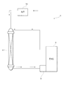
はじめに、図1を参照して、本実施形態のリザーブタンク10が適用されるエンジン冷却装置1の概要について説明する。図1に示されるエンジン冷却装置1は、車両のエンジン2を適正な温度に冷却するための装置である。エンジン冷却装置1は、エンジン2、ポンプ3、及びラジエータ4が環状に接続された構造からなる。このエンジン冷却装置1では、ポンプ3により圧送される冷却水がエンジン2及びラジエータ4を循環している。ラジエータ4において冷却された冷却水がエンジン2に供給されることにより、エンジン2が冷却される。このような冷却水の循環路のうち、エンジン2のシリンダヘッドとラジエータ4のアッパタンクとを接続する経路に対してリザーブタンク10が並列に配置されている。リザーブタンク10には、エンジン2のシリンダヘッドから冷却水の一部が流入して貯留される。リザーブタンク10は、冷却水中の気泡などの気体を分離して冷却水を貯留する。リザーブタンク10に貯留される冷却水はポンプ3の作動によりラジエータ4のアッパタンクに供給される。本実施形態のリザーブタンク10により分離される液体及び気体はそれぞれ、冷却水、及び冷却水に含まれる気体である。
Hereinafter, embodiments of the reserve tank will be described with reference to the drawings. To facilitate understanding of the description, the same components are denoted by the same reference numerals as much as possible in each drawing, and redundant description will be omitted.
<First embodiment>
First, an outline of an engine cooling device 1 to which a
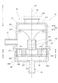
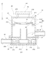
次に、リザーブタンク10の具体的な構造について説明する。図2に示されるように、リザーブタンク10は、タンク本体20と、タンク本体20の内部に収容される流路形成プレート30とを備えている。なお、図2において矢印Z1で示される方向は鉛直方向上方を示し、矢印Z2で示される方向は鉛直方向下方を示す。
Next, a specific structure of the
タンク本体20は、軸線m1を中心に円筒状に形成されている。タンク本体20は、軸線m1に沿った方向において上側タンク部21と下側タンク部22とに分割されて構成されている。タンク本体20は、上側タンク部21と下側タンク部22とが接合されることにより構成されている。タンク本体20は、樹脂材料等により形成されている。なお、タンク本体20の材料として、透過性を有するポリプロピレン等の樹脂材料を用いれば、その内部の冷却水の水位を目視で確認することが可能である。
The
下側タンク部22の内部には、流路形成プレート30が収容されている。下側タンク部22の内周面には、流路形成プレート30の外周部分が嵌め込まれる溝222が形成されている。この溝222に嵌め込まれた流路形成プレート30の外周部分の上面が上側タンク部21により押さえ込まれることにより、流路形成プレート30がタンク本体20に固定されている。なお、溝222に代えて、流路形成プレート30の底面を支える複数のリブを下側タンク部22の内周面に形成した上で、これらの複数のリブと上側タンク部21とにより流路形成プレート30の外周部分を挟み込むことにより、流路形成プレート30をタンク本体20に対して固定してもよい。下側タンク部22の底壁部221には、タンク本体20の内部に冷却水を流入させるための流入パイプ40が取り付けられている。
The flow
上側タンク部21の内部には、冷却水に含まれる気泡を分離して冷却水を貯留する気液分離室R1が形成されている。図中の符号R10は、気液分離室R1において主に気体が存在する気体層を示し、図中の符号R11は、気液分離室R1において主に冷却水が存在する液体層を示している。気液分離室R1は、上側タンク部21の内壁面と流路形成プレート30の上面とにより区画される空間として形成されている。
Inside the
上側タンク部21の側壁部210には、気液分離室R1内に貯留される冷却水を外部に流出させるための流出パイプ41が取り付けられている。流出パイプ41は、その内部流路が気液分離室R1内に貯留される冷却水の液面LSよりも下方に位置し、且つその内部流路が円筒部310の先端部よりも下方に位置するように配置されている。
An
上側タンク部21の上壁部211には、タンク本体20の内部に冷却水を注入するための円筒状の注水口212が形成されている。注水口212には、加圧キャップ50が装着される。この加圧キャップ50により、タンク本体20の内部を含め、エンジン冷却装置1の各部に付与される圧力が所定の圧力に調整することが可能となっている。
A
流路形成プレート30は、上側プレート31と、下側プレート32とにより構成されている。
上側プレート31は、軸線m1を中心に円柱状に形成されている。上側プレート31の上面の中央部には、軸線m1を中心軸として円筒状に形成される円筒部310が気液分離室R1の内部に延びるように形成されている。すなわち、円筒部310は、タンク本体20の内部に配置されている。上側プレート31は、上側タンク部21の内壁面と共に気液分離室R1を区画して形成している。
The flow
The
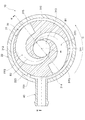
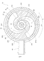
図3に示されるように、上側プレート31の内部には、独立した2つの流路FP1,FP2を構成するための凹状溝311,312が形成されている。凹状溝311,312は、軸線m1を中心とする径方向外側から上側プレート31の中央に向かって円弧状に曲げられるように形成されている。凹状溝311,312は、上側プレート31の中央部分に形成された空間からなる合流部313で合流している。合流部313は、円筒部310の一端部から円筒部310の内部に連通されている。凹状溝311,312は、軸線m1を中心とする径方向において合流部313の外側から合流部313に向かうほど、その幅が狭くなるように形成されている。
As shown in FIG. 3, inside the
図1に示されるように、下側プレート32は、上側プレート31の底面に組み付けられている。下側プレート32は、上側プレート31に形成されている凹状溝311,312及び合流部313のそれぞれの開口部分を閉塞している。下側プレート32と上側プレート31の凹状溝311とにより囲まれる空間は第1流路FP1を構成している。また、下側プレート32と上側プレート31の凹状溝312とにより囲まれる空間は第2流路FP2を構成している。図4に示されるように、下側プレート32の外縁部分には、軸線m1を中心として点対称となる位置に流入口320,321が形成されている。図1に示されるように、流入口320は、流入パイプ40から流入した冷却水を第1流路FP1に導入する部分である。流入口321は、流入パイプ40から流入した冷却水を第2流路FP2に導入する部分である。
As shown in FIG. 1, the
次に、本実施形態のリザーブタンク10の動作例について説明する。
流入パイプ40から流入した冷却水は、流路形成プレート30の流入口320,321を通じて第1流路FP1及び第2流路FP2にそれぞれ流入する。第1流路FP1及び第2流路FP2にそれぞれ流入した冷却水は、第1流路FP1及び第2流路FP2に沿って流路形成プレート30の外側から内側に向かって旋回しつつ流れて、合流部313で合流する。この際、図3に示されるように、第1流路FP1から合流部313に流入する流体の流れ方向B1と、第2流路FP2から合流部313に流入する流体の流れ方向B2とが対向している。これらの対向する流れ方向を有する流体が合流部313に流れ込むことにより合流部313の冷却水に旋回流を発生させることができる。旋回流となった冷却水は、図2に矢印B3で示されるように円筒部310の内部を旋回しつつ上方に向かって流れ、円筒部310の先端部から気液分離室R1に吐出される。この際、冷却水が旋回しながら気液分離室R1に流入することにより、気液分離室R1内には冷却水の渦が形成されるため、その遠心力により液体状の冷却水が気液分離室R1の外周部分に向かって流れるとともに、冷却水に含まれる気泡が気液分離室R1の中央部分付近に集まる。気液分離室R1の中央部付近に集まった気泡は、気液分離室R1の上方に貯まる。そのため、気液分離室R1の上方には気体層R10が形成され、その下方には液体層R11が形成されることになる。液体層R11に貯留される冷却水は、流出パイプ41を通じて外部に流出する。
Next, an operation example of the
The cooling water flowing from the
以上説明した本実施形態のリザーブタンク10によれば、以下の(1)〜(4)に示される作用及び効果を得ることができる。
(1)流路FP1,FP2は、軸線m1を中心とする径方向において合流部313の外側から合流部313に向かって冷却水が流れるように合流部313を中心に点対称に形成されている。合流部313は、円筒部310の一端部に設けられ、流路FP1,FP2をそれぞれ流れる冷却水を合流させて円筒部310の一端部に流入させる。合流部313から円筒部310の内部に流入した冷却水が円筒部310の他端部から気液分離室R1に流入する。このような構成によれば、流路FP1,FP2をそれぞれ流れる冷却水の流れにより合流部313の冷却水に旋回流を発生させることができるため、一つの流入口から流入する冷却水の流れにより旋回流を発生させる従来のリザーブタンクと比較すると、冷却水に旋回流を発生させ易くなる。よって、冷却水に旋回流を発生させるために必要な冷却水の流速を遅くすることが可能であるため、結果的にポンプ3の負荷を軽減することができる。
According to the
(1) The flow paths FP1 and FP2 are formed point-symmetrically about the
(2)流路形成プレート30において気液分離室R1に面する外面である上面の中央部には、円筒部310が形成されている。流路形成プレート30において上面とは反対側の面である底面には、流路FP1,FP2に冷却水をそれぞれ流入させる流入口320,321が形成されている。流入パイプ40は、流路形成プレート30の底面に対向するタンク本体20の底壁部221に設けられている。このような構成によれば、タンク本体20の側壁部210,220に流入パイプ40が設けられる場合と比較すると、軸線m1を中心とする径方向外側へのタンク本体20の大型化を回避することができる。
(2) A
(3)流路FP1,FP2は、軸線m1を中心とする径方向において合流部313の外側から合流部313に向かって冷却水を旋回させて流すように形成されている。このような構成によれば、流路FP1,FP2から合流部313に流入する冷却水に旋回流を更に発生させ易くなるため、ポンプ3の負荷を更に軽減することができる。
(3) The flow paths FP1 and FP2 are formed so as to swirl and flow the cooling water from the outside of the
(4)流路FP1,FP2は、軸線m1を中心とする径方向において合流部313の外側から合流部313に向かうほど流路断面積が小さくなるように形成されている。これにより、流路FP1,FP2内を流れる冷却水の流速が合流部313の外側から合流部313に向かうほど速くなるため、流路FP1,FP2から合流部313に流入する冷却水に旋回流を更に発生させ易くなる。よって、ポンプ3の負荷を更に軽減することができる。
(4) The flow paths FP1 and FP2 are formed such that the flow path cross-sectional area decreases from the outside of the
(変形例)
次に、第1実施形態のリザーブタンク10の変形例について説明する。
図5に示されるように、本変形例のリザーブタンク10では、円筒部310の内壁面の上端の角部にR面取り加工が施されている。このような構成によれば、円筒部310の内壁面の上端の角部が直角に尖った形状を有している場合と比較すると、円筒部310から気液分離室R1に流入する冷却水の旋回流が阻害され難くなる。これにより、気液分離室R1において冷却水の渦が形成され易くなるため、冷却水に含まれる気泡をより的確に分離することが可能となる。
(Modification)
Next, a modified example of the
As shown in FIG. 5, in the
なお、円筒部310の内壁面の上端の角部には、R面取り加工に代えて、C面取り加工が施されていてもよい。
<第2実施形態>
次に、リザーブタンク10の第2実施形態について説明する。以下、第1実施形態のリザーブタンク10との相違点を中心に説明する。
Note that a corner at the upper end of the inner wall surface of the
<Second embodiment>
Next, a second embodiment of the
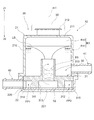
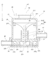
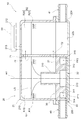
図6及び図7に示されるように、本実施形態のリザーブタンク10では、タンク本体20の下側タンク部22の側壁部220に流入パイプ40が設けられている点で、第1実施形態のリザーブタンク10と異なる。本実施形態のリザーブタンク10では、この流入パイプ40から流入する冷却水が流路形成プレート30の外周部分から各流路FP1,FP2に流入するようになっている。
As shown in FIGS. 6 and 7, in the
具体的には、図7に示されるように、流路形成プレート30は、その外周部分が下側タンク部22の底壁部221と上側タンク部21とに挟まれることによりタンク本体20に固定されている。図6に示されるように、流路形成プレート30の外壁部と下側タンク部22の内壁部との間には円環状の隙間が形成されている。この隙間は、流入パイプ40から冷却水が流入する外周流路FP3を構成している。
Specifically, as shown in FIG. 7, the flow
流路形成プレート30の上側プレート31の外周面には、外周流路FP3を流れる冷却水を第1流路FP1に流入させるための流入口314、及び外周流路FP3を流れる冷却水を第2流路FP2に流入させるための流入口315が形成されている。流入口314及び流入口315は、合流部313を中心として点対称に配置されている。
On the outer peripheral surface of the
下側タンク部22の内壁部には、外周流路FP3を横断するように突出部223が形成されている。突出部223は、流入パイプ40から外周流路FP3に流入した冷却水の流れ方向を図中の矢印Cで示される周方向に規制するために設けられている。矢印Cで示される方向は、軸線m1を中心として流入パイプ40、第1流路FP1の流入口314、第2流路FP2の流入口314の順で周回する方向である。
A
以上説明した本実施形態のリザーブタンク10によれば、上記の(1),(3),(4)に示される作用及び効果に加え、以下の(5)に示される作用及び効果を得ることができる。
(5)流入パイプ40は、流路形成プレート30の外周面に対向するタンク本体20の側壁部220に設けられている。これにより、第1実施形態のリザーブタンク10のように、タンク本体20の底壁部221に流入パイプ40が設けられる場合と比較すると、タンク本体20の軸方向の大型化を回避することができる。
According to the
(5) The
<第3実施形態>
次に、リザーブタンク10の第3実施形態について説明する。以下、第2実施形態のリザーブタンク10との相違点を中心に説明する。
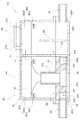
図8及び図9に示されるように、本実施形態のリザーブタンク10では、円筒部310の内部に円柱状の棒状部材33が配置されている。なお、棒状部材33は円管状に形成されていてもよい。棒状部材33は、下側プレート32の中央部から軸線m1に沿って上方に延びるように形成されている。棒状部材33は、円筒部310の内部を通じて気液分離室R1の内部まで延びるように形成されている。棒状部材33は、円筒部310と同軸上に配置されている。棒状部材33の先端部は、円筒部310の先端部よりも気液分離室R1の内部に延びている。
<Third embodiment>
Next, a third embodiment of the
As shown in FIGS. 8 and 9, in the
以上説明した本実施形態のリザーブタンク10によれば、以下の(6)に示される作用及び効果を更に得ることができる。
(6)本実施形態のリザーブタンク10では、円筒部310内に流入した冷却水が棒状部材33の外周面に沿って流れるため、円筒部310内を流れる冷却水に旋回流を更に発生させ易くなる。これにより、冷却水に旋回流を発生させるために必要な冷却水の流速を遅くすることが可能であるため、リザーブタンクに冷却水を圧送するポンプの負荷を更に軽減することができる。
According to the
(6) In the
<第4実施形態>
次に、第4実施形態のリザーブタンク10について説明する。以下、第3実施形態のリザーブタンク10との相違点を中心に説明する。
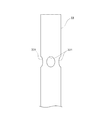
図10に示されるように、本実施形態のリザーブタンク10では、棒状部材33の外周面に凸部330が形成されている。凸部330は、棒状部材33の外周面において円筒部310の先端部に対向する位置に形成されている。
<Fourth embodiment>
Next, a
As shown in FIG. 10, in the
以上説明した本実施形態のリザーブタンク10によれば、以下の(7)に示される作用及び効果を更に得ることができる。
(7)棒状部材33に沿って流れる冷却水に含まれる気泡が凸部330に当たることにより、冷却水から気泡が分離し易くなる。特に、棒状部材33の外周面において円筒部310の先端部に対向する位置に凸部330が形成されている場合、円筒部310の内部から気液分離室R1に冷却水が吐出される際に、その冷却水に含まれる気泡が凸部330により分離されることになるため、より効率的に冷却水から気泡を分離することが可能となる。
According to the
(7) Bubbles contained in the cooling water flowing along the rod-shaped
(変形例)
次に、第4実施形態のリザーブタンク10の変形例について説明する。
図11に示されるように、本変形例のリザーブタンク10では、棒状部材33の外周面に、凸部330に代えて、凹部331が設けられている。このような構成であっても、棒状部材33に沿って流れる冷却水に含まれる気泡が凹部331に当たることにより、冷却水から気泡が分離し易くなる。
(Modification)
Next, a modified example of the
As shown in FIG. 11, in the
<第5実施形態>
次に、リザーブタンク10の第5実施形態について説明する。以下、第2実施形態のリザーブタンク10との相違点を中心に説明する。
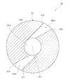
本実施形態のリザーブタンク10では、図12に示される上側プレート31が用いられている。図12に示されるように、本実施形態の上側プレート31には、軸線m1を中心とする径方向において合流部313の外側から合流部313に向かって直線状に延びるように凹状溝311,312が形成されている。各凹状溝311,312の一方の側壁部は、円筒部310の内壁面の接線方向に延びるように形成されている。各凹状溝311,312の他方の側壁部は、上側プレート31の外周に向かうほど、一方の側壁部から離間するように形成されている。これにより、凹状溝311,312は、軸線m1を中心とする径方向において合流部313の外側に向かうほど、その幅が狭くなるように形成されている。この上側プレート31の底面に下側プレート32が組み付けられることにより、下側プレート32と上側プレート31の凹状溝311とにより囲まれる空間が第1流路FP1を構成し、下側プレート32と上側プレート31の凹状溝312とにより囲まれる空間が第2流路FP2を構成している。
<Fifth embodiment>
Next, a fifth embodiment of the
In the
以上説明した本実施形態のリザーブタンク10によれば、上記の(1),(2),(4)に示される作用及び効果に加え、以下の(8)に示される作用及び効果を得ることができる。
(8)流路FP1,FP2は、軸線m1を中心とする径方向において合流部313の外側から合流部313に向かって冷却水を直線状に流すように形成されている。このような構成によれば、第1実施形態のような円弧状の流路FP1,FP2を流路形成プレート30に形成する場合と比較すると、流路形成プレート30の製造が容易になる。
According to the
(8) The flow paths FP1 and FP2 are formed so that the cooling water flows linearly from the outside of the
<第6実施形態>
次に、第6実施形態のリザーブタンク10について説明する。以下、第2実施形態のリザーブタンク10との相違点を中心に説明する。
本実施形態のリザーブタンク10では、図13に示される上側プレート31が用いられている。図13に示されるように、本実施形態の上側プレート31には、凹状溝311,312に加え、凹状溝316,317が更に形成されている。凹状溝316,317は、合流部313を中心に点対称に形成されている。凹状溝311,312,316,317は、軸線m1を中心とする周方向において等間隔ピッチで形成されている。これらの凹状溝311,312,316,317と下側プレート32とにより囲まれる空間は第1〜第4流路FP1〜FP4を構成している。
<Sixth embodiment>
Next, a
In the
以上説明した本実施形態のリザーブタンク10によれば、以下の(9)に示される作用及び効果を更に得ることができる。
(9)本実施形態のリザーブタンク10では、第2実施形態のリザーブタンク10と比較すると、流路形成プレート30に形成される流路の数が増えているため、円筒部310内の冷却水に旋回流を更に発生させ易くなる。これにより、冷却水に旋回流を発生させるために必要な冷却水の流速を遅くすることが可能であるため、リザーブタンクに冷却水を圧送するポンプの負荷を更に軽減することができる。
According to the
(9) In the
<第7実施形態>
次に、第7実施形態のリザーブタンク10について説明する。以下、第2実施形態のリザーブタンク10との相違点を中心に説明する。
図14に示されるように、本実施形態のリザーブタンク10は、気液分離室R1に貯留された冷却水の液面LSに浮かぶように配置される浮遊プレート60を更に備えている。浮遊プレート60は、冷却水の液面LSに浮かぶことが可能なように、冷却水よりも比重の軽い樹脂材料により形成されている。
<Seventh embodiment>
Next, a
As shown in FIG. 14, the
浮遊プレート60は、軸線m1を中心に円盤状に形成されている。浮遊プレート60の中央部には貫通孔61が形成されている。また、浮遊プレート60の底面62は、浮遊プレート60の中央部に位置する部分よりも浮遊プレート60の外周部に位置する部分の方が気液分離室R1の天井面213に接近するようにテーパ状に形成されている。
The floating
以上説明した本実施形態のリザーブタンク10によれば、上記の(10),(11)に示される作用及び効果を更に得ることができる。
(10)浮遊プレート60は、気液分離室R1内に形成される冷却水の渦上で回転しながら留まる。円筒部310の先端部から吐出された冷却水に含まれる気泡は、気液分離室R1内を上方に移動して浮遊プレート60の底面62に付着する。よって、冷却水に含まれる気泡は浮遊プレート60の底面62において捕集される。また、浮遊プレート60自体が回転しているため、浮遊プレート60の底面62で捕集された気泡は、遠心力により浮遊プレート60の外周に向かって移動して気液分離室R1の気体層R10に放出される。そのため、冷却水に含まれる気泡を、より的確に気液分離室R1の気体層R10に導くことができるため、冷却水に含まれる気泡を更に分離させ易くすることができる。
According to the
(10) The floating
(11)例えば車両が坂道を走行している状況では、軸線m1が鉛直方向に対して所定角度をなすようにリザーブタンク10が傾くことにより、気液分離室R1内の冷却水の液面LSが傾く可能性がある。また、車両が悪路を走行している状況では、リザーブタンク10が振動するため、同様に気液分離室R1内の冷却水の液面LSが傾く可能性がある。このようにして気液分離室R1内の冷却水の液面LSに乱れが生じると、気体層R10に存在する気体が、液体層R11内の冷却水に混入する懸念がある。この点、本実施形態のリザーブタンク10では、気液分離室R1内の冷却水の液面LSに浮かぶ浮遊プレート60により気液分離室R1内の冷却水の液面LSが乱れ難くなるため、気体層R10に存在する気体が、液体層R11内の冷却水に混入し難くなる。
(11) For example, in a situation where the vehicle is traveling on a slope, the
<第8実施形態>
次に、第8実施形態のリザーブタンク10について説明する。以下、第2実施形態のリザーブタンク10との相違点を中心に説明する。
図15に示されるように、本実施形態のタンク本体20の内部には、隔壁70を隔てて気液分離室R1に隣接するように貯留室R2が更に配置されている。図中の符号R20は貯留室R2の気体層を示し、符号R21は貯留室R2の液体層を示している。隔壁70には、気液分離室R1の気体層R10に存在する気体を貯留室R2の気体層R20に導入するための気体導入孔71と、気液分離室R1の液体層R11に存在する冷却水を貯留室R2の液体層R21に導入するための液体導入孔72とが形成されている。隔壁70に対して貯留室R2を挟んで反対側に位置するタンク本体20の側壁部224には、貯留室R2の液体層R21に貯留された冷却水を外部に流出させるための流出パイプ41が取り付けられている。
<Eighth embodiment>
Next, a
As shown in FIG. 15, a storage chamber R2 is further disposed inside the tank
以上説明した本実施形態のリザーブタンク10によれば、以下の(12)に示される作用及び効果を更に得ることができる。
(12)冷却水及び気体を貯留室R2に更に貯留することができるため、リザーブタンク10を大型化することが可能となる。
According to the
(12) Since the cooling water and the gas can be further stored in the storage chamber R2, the size of the
<第9実施形態>
次に、第9実施形態のリザーブタンク10について説明する。以下、第8実施形態のリザーブタンク10との相違点を中心に説明する。
図16に示されるように、本実施形態のタンク本体20は、貯留室R2の内部において隔壁70に対して平行に配置される仕切り板80を更に備えている。仕切り板80は、その先端部が隔壁70の液体導入孔72よりも貯留室の天井面213の近くに位置するように貯留室R2の底面225から貯留室R2の天井面213に向かう途中まで延びるように形成されている。
<Ninth embodiment>
Next, a
As shown in FIG. 16, the tank
以上説明した本実施形態のリザーブタンク10によれば、以下の(13)に示される作用及び効果を更に得ることができる。
(13)仮に気液分離室R1から液体導入孔72を通じて貯留室R2に流入する冷却水に気泡が含まれているような場合であっても、その気泡を含む冷却水が仕切り板80に当たることにより、冷却水と気泡とを分離することができる。これにより、気泡を含む冷却水が流出パイプ41を通じて外部に排出されるような状況を生じ難くすることができる。
According to the
(13) Even if the cooling water flowing into the storage chamber R2 from the gas-liquid separation chamber R1 through the
<他の実施形態>
なお、上記実施形態は、以下の形態にて実施することもできる。
・第4実施形態のリザーブタンク10では、凸部330及び凹部331の位置を、棒状部材33の外周面の任意の位置に変更してもよい。また、棒状部材33の外周面に、凸部330及び凹部331の両方を形成してもよい。
<Other embodiments>
Note that the above embodiment can also be implemented in the following forms.
-In the
・各実施形態のリザーブタンク10は、車両のエンジンの冷却水以外の液体を用いるものであってもよい。
・本開示は上記の具体例に限定されるものではない。上記の具体例に、当業者が適宜設計変更を加えたものも、本開示の特徴を備えている限り、本開示の範囲に包含される。前述した各具体例が備える各要素、及びその配置、条件、形状等は、例示したものに限定されるわけではなく適宜変更することができる。前述した各具体例が備える各要素は、技術的な矛盾が生じない限り、適宜組み合わせを変えることができる。
-The
-The present disclosure is not limited to the above specific examples. The above-described specific examples in which a person skilled in the art appropriately changes the design are also included in the scope of the present disclosure as long as they have the features of the present disclosure. The components included in each of the specific examples described above, and their arrangement, conditions, shapes, and the like are not limited to those illustrated, but can be appropriately changed. The elements included in each of the specific examples described above can be appropriately changed in combination as long as there is no technical contradiction.
FP1,FP2,FP3,FP4:流路
R1:気液分離室
R2:貯留室
10:リザーブタンク
20:タンク本体
30:流路形成プレート
33:棒状部材
40:流入パイプ
60:浮遊プレート
61:貫通孔
62:底面
71:気体導入孔
72:液体導入孔
80:仕切り板
221:底壁部
220,224:側壁部
310:円筒部
313:合流部
314,315,320,321:流入口
330:凸部
331:凹部
FP1, FP2, FP3, FP4: flow path R1: gas-liquid separation chamber R2: storage chamber 10: reserve tank 20: tank body 30: flow path forming plate 33: rod-shaped member 40: inflow pipe 60: floating plate 61: through hole 62: bottom surface 71: gas introduction hole 72: liquid introduction hole 80: partition plate 221:
Claims (13)
前記タンク本体の内部に配置され、所定の軸線を中心に円筒状に形成される円筒部(310)と、
前記液体が流れ、独立して形成される複数の流路(FP1,FP2,FP3,FP4)と、
前記円筒部の一端部に設けられ、複数の前記流路をそれぞれ流れる前記液体を合流させて前記円筒部の一端部に流入させる合流部(313)と、を備え、
複数の前記流路は、前記軸線を中心とする径方向において前記合流部の外側から前記合流部に向かって前記液体が流れるように前記合流部を中心に点対称に形成され、
前記合流部から前記円筒部の内部に流入した液体が前記円筒部の他端部から前記気液分離室に流入する
リザーブタンク。 A tank body (20) having therein a gas-liquid separation chamber (R1) for separating gas in liquid and storing the liquid;
A cylindrical portion (310) disposed inside the tank body and formed in a cylindrical shape around a predetermined axis;
A plurality of independently formed flow paths (FP1, FP2, FP3, FP4) through which the liquid flows;
A merging portion (313) provided at one end of the cylindrical portion and merging the liquids flowing through the plurality of flow paths and flowing into the one end of the cylindrical portion,
The plurality of flow paths are formed point-symmetrically around the junction so that the liquid flows from the outside of the junction toward the junction in a radial direction around the axis,
A reserve tank in which a liquid flowing into the inside of the cylindrical portion from the junction flows into the gas-liquid separation chamber from the other end of the cylindrical portion.
前記タンク本体に取り付けられ、前記タンク本体の外部から複数の前記流路に前記液体を流入させる流入パイプ(40)と、を更に備え、
前記流路形成プレートにおいて前記気液分離室に面する外面を上面とし、前記上面とは反対側の面を底面とするとき、
前記流路形成プレートの前記上面の中央部には、前記円筒部が形成され、
前記流路形成プレートの前記底面には、複数の前記流路に前記液体をそれぞれ流入させる複数の流入口(320,321)が形成され、
前記流入パイプは、前記流路形成プレートの前記底面に対向する前記タンク本体の底壁部(221)に設けられている
請求項1に記載のリザーブタンク。 A flow path forming plate (30), which is formed in a columnar shape around the axis, partitions and forms the gas-liquid separation chamber together with the inner wall surface of the tank body, and has a plurality of the flow paths formed therein; ,
An inflow pipe (40) attached to the tank body and configured to allow the liquid to flow into the plurality of flow paths from outside the tank body.
When the outer surface facing the gas-liquid separation chamber in the flow path forming plate is an upper surface, and the surface opposite to the upper surface is a bottom surface,
At the center of the upper surface of the channel forming plate, the cylindrical portion is formed,
A plurality of inlets (320, 321) are formed on the bottom surface of the flow path forming plate to allow the liquid to flow into the plurality of flow paths, respectively.
The reserve tank according to claim 1, wherein the inflow pipe is provided on a bottom wall (221) of the tank body facing the bottom surface of the flow path forming plate.
前記タンク本体に取り付けられ、前記タンク本体の外部から複数の前記流路に前記液体を流入させる流入パイプ(40)と、を更に備え、
前記流路形成プレートにおいて前記気液分離室に面する外面を上面とするとき、
前記流路形成プレートの前記上面の中央部には、前記円筒部が形成され、
前記流路形成プレートの外周面には、複数の前記流路に前記液体をそれぞれ流入させる複数の流入口(314,315)が形成され、
前記流入パイプは、前記流路形成プレートの外周面に対向する前記タンク本体の側壁部(220)に設けられている
請求項1に記載のリザーブタンク。 A flow path forming plate (30), which is formed in a columnar shape around the axis, partitions and forms the gas-liquid separation chamber together with the inner wall surface of the tank body, and has a plurality of the flow paths formed therein; ,
An inflow pipe (40) attached to the tank body and configured to allow the liquid to flow into the plurality of flow paths from outside the tank body.
When the outer surface facing the gas-liquid separation chamber is the upper surface in the flow path forming plate,
At the center of the upper surface of the channel forming plate, the cylindrical portion is formed,
A plurality of inlets (314, 315) are formed on the outer peripheral surface of the flow path forming plate to allow the liquid to flow into the plurality of flow paths, respectively.
The reserve tank according to claim 1, wherein the inflow pipe is provided on a side wall (220) of the tank body facing an outer peripheral surface of the flow path forming plate.
請求項1〜3のいずれか一項に記載のリザーブタンク。 The plurality of flow paths are formed so as to linearly flow the liquid from the outside of the junction toward the junction in a radial direction about the axis. Reserve tank according to the item.
請求項1〜3のいずれか一項に記載のリザーブタンク。 The plurality of flow paths are formed so as to swirl and flow the liquid from outside the confluence to the confluence in a radial direction about the axis. Reserve tank according to the item.
前記隔壁には、前記気液分離室の気体層に存在する気体を前記貯留室に導入するための気体導入孔(71)と、前記気液分離室の液体層に存在する液体を前記貯留室に導入するための液体導入孔(72)とが形成されている
請求項1〜5のいずれか一項に記載のリザーブタンク。 The tank body further includes a storage chamber (R2) disposed adjacent to the gas-liquid separation chamber with a partition wall (70) interposed therebetween,
The partition has a gas introduction hole (71) for introducing gas present in the gas layer of the gas-liquid separation chamber into the storage chamber, and a liquid present in the liquid layer of the gas-liquid separation chamber in the storage chamber. The reserve tank according to any one of claims 1 to 5, wherein a liquid introduction hole (72) for introducing the liquid into the reservoir tank is formed.
前記タンク本体は、前記貯留室の内部において前記隔壁に対して平行に配置される仕切り板(80)を更に有し、
前記仕切り板は、その先端部が前記液体導入孔よりも前記貯留室の天井面の近くに位置するように前記貯留室の底面から前記貯留室の天井面に向かう途中まで延びるように形成されている
請求項6に記載のリザーブタンク。 An outflow pipe that allows the liquid stored in the storage chamber to flow out is attached to the side wall (224) of the tank body that is located on the opposite side of the storage chamber with respect to the partition wall,
The tank body further includes a partition plate (80) arranged inside the storage chamber in parallel with the partition.
The partition plate is formed so as to extend from the bottom surface of the storage chamber to a partway toward the ceiling surface of the storage chamber such that a tip end thereof is located closer to the ceiling surface of the storage chamber than the liquid introduction hole. The reserve tank according to claim 6.
請求項1〜7のいずれか一項に記載のリザーブタンク。 The plurality of flow paths are formed such that the cross-sectional area of the flow path decreases from the outside of the junction to the junction in a radial direction about the axis. Reserve tank according to the item.
前記棒状部材の先端部は、前記円筒部の先端部よりも前記気液分離室の内部に延びている
請求項1〜8のいずれか一項に記載のリザーブタンク。 A cylindrical or tubular rod-shaped member (33) disposed coaxially with the cylindrical portion inside the cylindrical portion;
The reserve tank according to any one of claims 1 to 8, wherein a tip portion of the rod-shaped member extends more inside the gas-liquid separation chamber than a tip portion of the cylindrical portion.
請求項9に記載のリザーブタンク。 The reserve tank according to claim 9, wherein at least one of a convex portion (330) and a concave portion (331) is formed on an outer peripheral surface of the rod-shaped member.
請求項10に記載のリザーブタンク。 The reserve tank according to claim 10, wherein at least one of the convex portion and the concave portion is formed at a position corresponding to a distal end portion of the cylindrical portion on the outer peripheral surface of the rod-shaped member.
前記浮遊プレートの中央部には、貫通孔(61)が形成されている
請求項1〜11のいずれか一項に記載のリザーブタンク。 A disk-shaped floating plate (60) arranged so as to float on the liquid surface of the liquid stored in the gas-liquid separation chamber;
The reserve tank according to any one of claims 1 to 11, wherein a through hole (61) is formed in a central portion of the floating plate.
請求項12に記載のリザーブタンク。 The bottom surface (62) of the floating plate facing the cylindrical portion has a portion located on the outer peripheral portion of the floating plate closer to a ceiling surface of the gas-liquid separation chamber than a portion located at the central portion of the floating plate. The reserve tank according to claim 12, which is formed in a tapered shape so as to approach.
Priority Applications (2)
| Application Number | Priority Date | Filing Date | Title |
|---|---|---|---|
| JP2018126016A JP7063149B2 (en) | 2018-07-02 | 2018-07-02 | Reserve tank |
| PCT/JP2019/025859 WO2020009030A1 (en) | 2018-07-02 | 2019-06-28 | Reserve tank |
Applications Claiming Priority (1)
| Application Number | Priority Date | Filing Date | Title |
|---|---|---|---|
| JP2018126016A JP7063149B2 (en) | 2018-07-02 | 2018-07-02 | Reserve tank |
Publications (3)
| Publication Number | Publication Date |
|---|---|
| JP2020002935A true JP2020002935A (en) | 2020-01-09 |
| JP2020002935A5 JP2020002935A5 (en) | 2020-10-08 |
| JP7063149B2 JP7063149B2 (en) | 2022-05-09 |
Family
ID=69060951
Family Applications (1)
| Application Number | Title | Priority Date | Filing Date |
|---|---|---|---|
| JP2018126016A Active JP7063149B2 (en) | 2018-07-02 | 2018-07-02 | Reserve tank |
Country Status (2)
| Country | Link |
|---|---|
| JP (1) | JP7063149B2 (en) |
| WO (1) | WO2020009030A1 (en) |
Cited By (2)
| Publication number | Priority date | Publication date | Assignee | Title |
|---|---|---|---|---|
| WO2021210283A1 (en) * | 2020-04-15 | 2021-10-21 | 株式会社デンソー | Reserve tank |
| JP2021169815A (en) * | 2020-04-15 | 2021-10-28 | 株式会社デンソー | Reserve tank |
Citations (12)
| Publication number | Priority date | Publication date | Assignee | Title |
|---|---|---|---|---|
| JPS5267067A (en) * | 1975-10-30 | 1977-06-03 | Enso Gutzeit Oy | Hydroocyclone device |
| JPS5843909U (en) * | 1981-09-18 | 1983-03-24 | トキコ株式会社 | Gas-liquid separator |
| EP0155553A2 (en) * | 1984-03-08 | 1985-09-25 | FÜLLPACK GmbH & Co. | Device for the treatment of a strong foaming liquid with a gas |
| JPH1043293A (en) * | 1996-08-08 | 1998-02-17 | Senko Ika Kogyo Kk | Device for removing bubble in liquid |
| JP2000312840A (en) * | 1999-04-28 | 2000-11-14 | Gijutsu Kaihatsu Sogo Kenkyusho:Kk | Apparatus for separating heavy and light components in mixed fluid |
| JP2001137615A (en) * | 1999-11-18 | 2001-05-22 | Sato Jushi Kogyo Kk | Bubble removing device |
| JP2001304402A (en) * | 2000-04-20 | 2001-10-31 | Hitachi Ltd | Automatic transmission |
| US20050224021A1 (en) * | 2002-07-12 | 2005-10-13 | Dirk Kastell | Compensation reservoir for a cooling circuit of an internal combustion engine |
| JP2015028336A (en) * | 2013-06-24 | 2015-02-12 | トヨタ車体株式会社 | Reservoir tank for engine cooling water |
| JP2015231608A (en) * | 2014-06-10 | 2015-12-24 | 横河電機株式会社 | Defoaming tank |
| WO2017056475A1 (en) * | 2015-09-28 | 2017-04-06 | 本田技研工業株式会社 | Expansion tank |
| JP2017166347A (en) * | 2016-03-14 | 2017-09-21 | 株式会社デンソー | Reserve tank |
-
2018
- 2018-07-02 JP JP2018126016A patent/JP7063149B2/en active Active
-
2019
- 2019-06-28 WO PCT/JP2019/025859 patent/WO2020009030A1/en not_active Ceased
Patent Citations (12)
| Publication number | Priority date | Publication date | Assignee | Title |
|---|---|---|---|---|
| JPS5267067A (en) * | 1975-10-30 | 1977-06-03 | Enso Gutzeit Oy | Hydroocyclone device |
| JPS5843909U (en) * | 1981-09-18 | 1983-03-24 | トキコ株式会社 | Gas-liquid separator |
| EP0155553A2 (en) * | 1984-03-08 | 1985-09-25 | FÜLLPACK GmbH & Co. | Device for the treatment of a strong foaming liquid with a gas |
| JPH1043293A (en) * | 1996-08-08 | 1998-02-17 | Senko Ika Kogyo Kk | Device for removing bubble in liquid |
| JP2000312840A (en) * | 1999-04-28 | 2000-11-14 | Gijutsu Kaihatsu Sogo Kenkyusho:Kk | Apparatus for separating heavy and light components in mixed fluid |
| JP2001137615A (en) * | 1999-11-18 | 2001-05-22 | Sato Jushi Kogyo Kk | Bubble removing device |
| JP2001304402A (en) * | 2000-04-20 | 2001-10-31 | Hitachi Ltd | Automatic transmission |
| US20050224021A1 (en) * | 2002-07-12 | 2005-10-13 | Dirk Kastell | Compensation reservoir for a cooling circuit of an internal combustion engine |
| JP2015028336A (en) * | 2013-06-24 | 2015-02-12 | トヨタ車体株式会社 | Reservoir tank for engine cooling water |
| JP2015231608A (en) * | 2014-06-10 | 2015-12-24 | 横河電機株式会社 | Defoaming tank |
| WO2017056475A1 (en) * | 2015-09-28 | 2017-04-06 | 本田技研工業株式会社 | Expansion tank |
| JP2017166347A (en) * | 2016-03-14 | 2017-09-21 | 株式会社デンソー | Reserve tank |
Cited By (2)
| Publication number | Priority date | Publication date | Assignee | Title |
|---|---|---|---|---|
| WO2021210283A1 (en) * | 2020-04-15 | 2021-10-21 | 株式会社デンソー | Reserve tank |
| JP2021169815A (en) * | 2020-04-15 | 2021-10-28 | 株式会社デンソー | Reserve tank |
Also Published As
| Publication number | Publication date |
|---|---|
| WO2020009030A1 (en) | 2020-01-09 |
| JP7063149B2 (en) | 2022-05-09 |
Similar Documents
| Publication | Publication Date | Title |
|---|---|---|
| JP2020002935A (en) | Reserve tank | |
| JP2015028336A (en) | Reservoir tank for engine cooling water | |
| US1020699A (en) | Centrifugal pump. | |
| CN103240188A (en) | Inertial separator for gas liquid separation | |
| JP2017166347A (en) | Reserve tank | |
| JP2013215634A (en) | Fine air bubble generator | |
| US6840386B2 (en) | Unitary centertube for a fluid filter | |
| CN110013173A (en) | Water dispenser and its water vapor separation nozzle | |
| JP2007263066A (en) | Gas-liquid separator | |
| JP2020186684A (en) | Reservoir tank | |
| EP2981342A2 (en) | Hydraulic fluid reservoir with improved de-aeration | |
| JP2021169815A (en) | Reserve tank | |
| JP2913117B2 (en) | Multistage ejector pump | |
| JP2718969B2 (en) | pump | |
| JP2020067081A (en) | Reserve tank | |
| JP2020002935A5 (en) | ||
| JP5868557B1 (en) | Oil separator | |
| WO2021210283A1 (en) | Reserve tank | |
| JP5791345B2 (en) | Gas-liquid separator | |
| JP2013163149A (en) | Microreactor for emulsion forming | |
| JP7440445B2 (en) | Reserve tank | |
| JP2005524022A (en) | Separation device in the oil circuit of motor vehicles | |
| CN201836108U (en) | Pump impeller | |
| CN114810892A (en) | Squeeze film damper and aircraft engine | |
| KR102940202B1 (en) | A vortex type microbubble generator with multiple liquid inlets |
Legal Events
| Date | Code | Title | Description |
|---|---|---|---|
| A521 | Request for written amendment filed |
Free format text: JAPANESE INTERMEDIATE CODE: A523 Effective date: 20200828 |
|
| A621 | Written request for application examination |
Free format text: JAPANESE INTERMEDIATE CODE: A621 Effective date: 20210601 |
|
| TRDD | Decision of grant or rejection written | ||
| A01 | Written decision to grant a patent or to grant a registration (utility model) |
Free format text: JAPANESE INTERMEDIATE CODE: A01 Effective date: 20220322 |
|
| A61 | First payment of annual fees (during grant procedure) |
Free format text: JAPANESE INTERMEDIATE CODE: A61 Effective date: 20220404 |
|
| R151 | Written notification of patent or utility model registration |
Ref document number: 7063149 Country of ref document: JP Free format text: JAPANESE INTERMEDIATE CODE: R151 |
|
| R250 | Receipt of annual fees |
Free format text: JAPANESE INTERMEDIATE CODE: R250 |