JP2020002949A - Fluid pump, and related system and method - Google Patents
Fluid pump, and related system and method Download PDFInfo
- Publication number
- JP2020002949A JP2020002949A JP2019111972A JP2019111972A JP2020002949A JP 2020002949 A JP2020002949 A JP 2020002949A JP 2019111972 A JP2019111972 A JP 2019111972A JP 2019111972 A JP2019111972 A JP 2019111972A JP 2020002949 A JP2020002949 A JP 2020002949A
- Authority
- JP
- Japan
- Prior art keywords
- plunger
- pump
- fluid
- reciprocating
- chamber
- Prior art date
- Legal status (The legal status is an assumption and is not a legal conclusion. Google has not performed a legal analysis and makes no representation as to the accuracy of the status listed.)
- Granted
Links
Images


Classifications
-
- F—MECHANICAL ENGINEERING; LIGHTING; HEATING; WEAPONS; BLASTING
- F04—POSITIVE - DISPLACEMENT MACHINES FOR LIQUIDS; PUMPS FOR LIQUIDS OR ELASTIC FLUIDS
- F04B—POSITIVE-DISPLACEMENT MACHINES FOR LIQUIDS; PUMPS
- F04B43/00—Machines, pumps, or pumping installations having flexible working members
- F04B43/0009—Special features
- F04B43/0054—Special features particularities of the flexible members
-
- F—MECHANICAL ENGINEERING; LIGHTING; HEATING; WEAPONS; BLASTING
- F04—POSITIVE - DISPLACEMENT MACHINES FOR LIQUIDS; PUMPS FOR LIQUIDS OR ELASTIC FLUIDS
- F04B—POSITIVE-DISPLACEMENT MACHINES FOR LIQUIDS; PUMPS
- F04B9/00—Piston machines or pumps characterised by the driving or driven means to or from their working members
- F04B9/08—Piston machines or pumps characterised by the driving or driven means to or from their working members the means being fluid
- F04B9/12—Piston machines or pumps characterised by the driving or driven means to or from their working members the means being fluid the fluid being elastic, e.g. steam or air
- F04B9/129—Piston machines or pumps characterised by the driving or driven means to or from their working members the means being fluid the fluid being elastic, e.g. steam or air having plural pumping chambers
- F04B9/131—Piston machines or pumps characterised by the driving or driven means to or from their working members the means being fluid the fluid being elastic, e.g. steam or air having plural pumping chambers with two mechanically connected pumping members
- F04B9/133—Piston machines or pumps characterised by the driving or driven means to or from their working members the means being fluid the fluid being elastic, e.g. steam or air having plural pumping chambers with two mechanically connected pumping members reciprocating movement of the pumping members being obtained by a double-acting elastic-fluid motor
-
- F—MECHANICAL ENGINEERING; LIGHTING; HEATING; WEAPONS; BLASTING
- F04—POSITIVE - DISPLACEMENT MACHINES FOR LIQUIDS; PUMPS FOR LIQUIDS OR ELASTIC FLUIDS
- F04B—POSITIVE-DISPLACEMENT MACHINES FOR LIQUIDS; PUMPS
- F04B43/00—Machines, pumps, or pumping installations having flexible working members
- F04B43/0009—Special features
- F04B43/0054—Special features particularities of the flexible members
- F04B43/0072—Special features particularities of the flexible members of tubular flexible members
-
- F—MECHANICAL ENGINEERING; LIGHTING; HEATING; WEAPONS; BLASTING
- F04—POSITIVE - DISPLACEMENT MACHINES FOR LIQUIDS; PUMPS FOR LIQUIDS OR ELASTIC FLUIDS
- F04B—POSITIVE-DISPLACEMENT MACHINES FOR LIQUIDS; PUMPS
- F04B43/00—Machines, pumps, or pumping installations having flexible working members
- F04B43/0009—Special features
- F04B43/0081—Special features systems, control, safety measures
-
- F—MECHANICAL ENGINEERING; LIGHTING; HEATING; WEAPONS; BLASTING
- F04—POSITIVE - DISPLACEMENT MACHINES FOR LIQUIDS; PUMPS FOR LIQUIDS OR ELASTIC FLUIDS
- F04B—POSITIVE-DISPLACEMENT MACHINES FOR LIQUIDS; PUMPS
- F04B43/00—Machines, pumps, or pumping installations having flexible working members
- F04B43/02—Machines, pumps, or pumping installations having flexible working members having plate-like flexible members, e.g. diaphragms
- F04B43/025—Machines, pumps, or pumping installations having flexible working members having plate-like flexible members, e.g. diaphragms two or more plate-like pumping members in parallel
-
- F—MECHANICAL ENGINEERING; LIGHTING; HEATING; WEAPONS; BLASTING
- F04—POSITIVE - DISPLACEMENT MACHINES FOR LIQUIDS; PUMPS FOR LIQUIDS OR ELASTIC FLUIDS
- F04B—POSITIVE-DISPLACEMENT MACHINES FOR LIQUIDS; PUMPS
- F04B43/00—Machines, pumps, or pumping installations having flexible working members
- F04B43/02—Machines, pumps, or pumping installations having flexible working members having plate-like flexible members, e.g. diaphragms
- F04B43/025—Machines, pumps, or pumping installations having flexible working members having plate-like flexible members, e.g. diaphragms two or more plate-like pumping members in parallel
- F04B43/026—Machines, pumps, or pumping installations having flexible working members having plate-like flexible members, e.g. diaphragms two or more plate-like pumping members in parallel each plate-like pumping flexible member working in its own pumping chamber
-
- F—MECHANICAL ENGINEERING; LIGHTING; HEATING; WEAPONS; BLASTING
- F04—POSITIVE - DISPLACEMENT MACHINES FOR LIQUIDS; PUMPS FOR LIQUIDS OR ELASTIC FLUIDS
- F04B—POSITIVE-DISPLACEMENT MACHINES FOR LIQUIDS; PUMPS
- F04B43/00—Machines, pumps, or pumping installations having flexible working members
- F04B43/02—Machines, pumps, or pumping installations having flexible working members having plate-like flexible members, e.g. diaphragms
- F04B43/06—Pumps having fluid drive
- F04B43/073—Pumps having fluid drive the actuating fluid being controlled by at least one valve
- F04B43/0733—Pumps having fluid drive the actuating fluid being controlled by at least one valve with fluid-actuated pump inlet or outlet valves; with two or more pumping chambers in series
-
- F—MECHANICAL ENGINEERING; LIGHTING; HEATING; WEAPONS; BLASTING
- F04—POSITIVE - DISPLACEMENT MACHINES FOR LIQUIDS; PUMPS FOR LIQUIDS OR ELASTIC FLUIDS
- F04B—POSITIVE-DISPLACEMENT MACHINES FOR LIQUIDS; PUMPS
- F04B43/00—Machines, pumps, or pumping installations having flexible working members
- F04B43/08—Machines, pumps, or pumping installations having flexible working members having tubular flexible members
- F04B43/084—Machines, pumps, or pumping installations having flexible working members having tubular flexible members the tubular member being deformed by stretching or distortion
-
- F—MECHANICAL ENGINEERING; LIGHTING; HEATING; WEAPONS; BLASTING
- F04—POSITIVE - DISPLACEMENT MACHINES FOR LIQUIDS; PUMPS FOR LIQUIDS OR ELASTIC FLUIDS
- F04B—POSITIVE-DISPLACEMENT MACHINES FOR LIQUIDS; PUMPS
- F04B43/00—Machines, pumps, or pumping installations having flexible working members
- F04B43/08—Machines, pumps, or pumping installations having flexible working members having tubular flexible members
- F04B43/086—Machines, pumps, or pumping installations having flexible working members having tubular flexible members with two or more tubular flexible members in parallel
-
- F—MECHANICAL ENGINEERING; LIGHTING; HEATING; WEAPONS; BLASTING
- F04—POSITIVE - DISPLACEMENT MACHINES FOR LIQUIDS; PUMPS FOR LIQUIDS OR ELASTIC FLUIDS
- F04B—POSITIVE-DISPLACEMENT MACHINES FOR LIQUIDS; PUMPS
- F04B43/00—Machines, pumps, or pumping installations having flexible working members
- F04B43/08—Machines, pumps, or pumping installations having flexible working members having tubular flexible members
- F04B43/10—Pumps having fluid drive
- F04B43/113—Pumps having fluid drive the actuating fluid being controlled by at least one valve
-
- F—MECHANICAL ENGINEERING; LIGHTING; HEATING; WEAPONS; BLASTING
- F04—POSITIVE - DISPLACEMENT MACHINES FOR LIQUIDS; PUMPS FOR LIQUIDS OR ELASTIC FLUIDS
- F04B—POSITIVE-DISPLACEMENT MACHINES FOR LIQUIDS; PUMPS
- F04B45/00—Pumps or pumping installations having flexible working members and specially adapted for elastic fluids
- F04B45/02—Pumps or pumping installations having flexible working members and specially adapted for elastic fluids having bellows
-
- F—MECHANICAL ENGINEERING; LIGHTING; HEATING; WEAPONS; BLASTING
- F04—POSITIVE - DISPLACEMENT MACHINES FOR LIQUIDS; PUMPS FOR LIQUIDS OR ELASTIC FLUIDS
- F04B—POSITIVE-DISPLACEMENT MACHINES FOR LIQUIDS; PUMPS
- F04B45/00—Pumps or pumping installations having flexible working members and specially adapted for elastic fluids
- F04B45/02—Pumps or pumping installations having flexible working members and specially adapted for elastic fluids having bellows
- F04B45/033—Pumps or pumping installations having flexible working members and specially adapted for elastic fluids having bellows having fluid drive
- F04B45/0336—Pumps or pumping installations having flexible working members and specially adapted for elastic fluids having bellows having fluid drive the actuating fluid being controlled by one or more valves
-
- F—MECHANICAL ENGINEERING; LIGHTING; HEATING; WEAPONS; BLASTING
- F04—POSITIVE - DISPLACEMENT MACHINES FOR LIQUIDS; PUMPS FOR LIQUIDS OR ELASTIC FLUIDS
- F04B—POSITIVE-DISPLACEMENT MACHINES FOR LIQUIDS; PUMPS
- F04B5/00—Machines or pumps with differential-surface pistons
- F04B5/02—Machines or pumps with differential-surface pistons with double-acting pistons
-
- F—MECHANICAL ENGINEERING; LIGHTING; HEATING; WEAPONS; BLASTING
- F04—POSITIVE - DISPLACEMENT MACHINES FOR LIQUIDS; PUMPS FOR LIQUIDS OR ELASTIC FLUIDS
- F04B—POSITIVE-DISPLACEMENT MACHINES FOR LIQUIDS; PUMPS
- F04B2201/00—Pump parameters
- F04B2201/02—Piston parameters
- F04B2201/0201—Position of the piston
-
- F—MECHANICAL ENGINEERING; LIGHTING; HEATING; WEAPONS; BLASTING
- F04—POSITIVE - DISPLACEMENT MACHINES FOR LIQUIDS; PUMPS FOR LIQUIDS OR ELASTIC FLUIDS
- F04B—POSITIVE-DISPLACEMENT MACHINES FOR LIQUIDS; PUMPS
- F04B43/00—Machines, pumps, or pumping installations having flexible working members
- F04B43/08—Machines, pumps, or pumping installations having flexible working members having tubular flexible members
- F04B43/10—Pumps having fluid drive
Landscapes
- Engineering & Computer Science (AREA)
- Mechanical Engineering (AREA)
- General Engineering & Computer Science (AREA)
- Reciprocating Pumps (AREA)
- Details Of Reciprocating Pumps (AREA)
Abstract
Description
本開示の実施の形態は、概して、往復プランジャを含む往復流体ポンプ、そのようなポンプと共に使用するための構成要素およびデバイス、ならびにそのような往復流体ポンプおよびデバイスを使用する方法に関する。 Embodiments of the present disclosure generally relate to reciprocating fluid pumps that include reciprocating plungers, components and devices for use with such pumps, and methods of using such reciprocating fluid pumps and devices.
往復流体ポンプは、多くの産業で使用されている。往復流体ポンプは一般に、ポンプ本体内に2つの流体チャンバを含む。典型的には、往復ピストン又はシャフトがポンプ本体内で前後に駆動される。従来、1つまたは複数のプランジャ(例えば、ダイヤフラムまたはベローズ)が往復ピストンまたはシャフトに接続されている。往復ピストンが一方向に移動すると、プランジャの移動の結果、流体が2つの流体チャンバの第1の流体チャンバ内に引き込まれ、第2のチャンバから放出される。往復ピストンが反対方向に移動すると、プランジャの移動により、流体が第1のチャンバから放出され、第2のチャンバ内に引き込まれる。チャンバ入口およびチャンバ出口は第1の流体チャンバと流体連通して提供されてもよく、別のチャンバ入口および別のチャンバ出口は第2の流体チャンバと流体連通して提供されてもよい。第1および第2の流体チャンバへのチャンバ入口は共通の単一のポンプ入口と流体連通していてもよく、第1および第2の流体チャンバからのチャンバ出口は共通の単一のポンプ出口と流体連通していてもよく、その結果、流体は単一の流体源からポンプ入口を介してポンプ内に引き込まれてもよく、流体は単一のポンプ出口を介してポンプから排出されてもよい。流体がチャンバ入口を介して流体チャンバにのみ流入することができ、流体がチャンバ出口を介して流体チャンバからのみ流出することができることを保証するために、逆止弁を各流体チャンバのチャンバ入口および出口に設けることができる。 Reciprocating fluid pumps are used in many industries. Reciprocating fluid pumps generally include two fluid chambers within the pump body. Typically, a reciprocating piston or shaft is driven back and forth within the pump body. Conventionally, one or more plungers (eg, diaphragms or bellows) are connected to a reciprocating piston or shaft. As the reciprocating piston moves in one direction, movement of the plunger results in fluid being drawn into the first of the two fluid chambers and expelled from the second chamber. As the reciprocating piston moves in the opposite direction, movement of the plunger causes fluid to be released from the first chamber and drawn into the second chamber. A chamber inlet and a chamber outlet may be provided in fluid communication with the first fluid chamber, and another chamber inlet and another chamber outlet may be provided in fluid communication with the second fluid chamber. The chamber inlets to the first and second fluid chambers may be in fluid communication with a common single pump inlet, and the chamber outlets from the first and second fluid chambers may be connected to a common single pump outlet. It may be in fluid communication, such that fluid may be drawn into the pump from a single source via the pump inlet and fluid may be discharged from the pump via a single pump outlet. . To ensure that fluid can only flow into the fluid chamber via the chamber inlet and fluid can only flow out of the fluid chamber via the chamber outlet, check valves are installed at the chamber inlet of each fluid chamber and An outlet can be provided.
本発明の目的は、往復プランジャを含む往復流体ポンプを提供することである。 It is an object of the present invention to provide a reciprocating fluid pump including a reciprocating plunger.
いくつかの実施形態では、本開示が対象流体を送り出す(ポンピングする)ための往復流体ポンプを含んでいる。往復流体ポンプは、ポンプ本体と、ポンプ本体内の対象流体チャンバと、第1のプランジャと、第2のプランジャとを含むことができる。第1のプランジャはポンプ本体の対象流体チャンバ内に配置することができ、第1のヘッド部と、第1のヘッド部から延びる第1のベローズとを含むことができ、第1のプランジャは往復運動で膨張および圧縮して対象流体をポンプ本体内の対象流体チャンバを介して送り出すように構成され、第1のヘッド部および第1のベローズは第1の断面寸法を有する。第2のプランジャはポンプ本体の対象流体チャンバ内に配置することができ、第2のヘッド部と、第2のヘッド部から延びる第2のベローズとを含むことができ、第2のプランジャは往復運動で膨張および圧縮して対象流体をポンプ本体内の対象流体チャンバを介して送り出すように構成され、第2のヘッド部および第2のベローズは第1の断面寸法よりも小さい第2の断面寸法を有する。 In some embodiments, the present disclosure includes a reciprocating fluid pump for pumping a target fluid. The reciprocating fluid pump can include a pump body, a target fluid chamber in the pump body, a first plunger, and a second plunger. The first plunger can be located in the target fluid chamber of the pump body and can include a first head portion and a first bellows extending from the first head portion, wherein the first plunger reciprocates. The first head portion and the first bellows are configured to expand and compress in motion to pump a target fluid through a target fluid chamber in the pump body, the first head portion and the first bellows having a first cross-sectional dimension. The second plunger may be located within the target fluid chamber of the pump body and may include a second head portion and a second bellows extending from the second head portion, wherein the second plunger reciprocates. The second head portion and the second bellows are configured to expand and compress in motion to pump a target fluid through a target fluid chamber in the pump body, the second head portion and the second bellows having a second cross-sectional dimension smaller than the first cross-sectional dimension Having.
1つまたは複数の実施形態では、本開示が対象流体を送り出すための往復流体ポンプを含んでいる。往復流体ポンプは、ポンプ本体と、ポンプ本体内の対象流体チャンバと、第1のプランジャと、第2のプランジャとを含むことができる。第1のプランジャは第1の断面寸法を有し、ポンプ本体の対象流体チャンバ内に位置することができ、第1のプランジャは可撓性材料を含み、ポンプ本体内の対象流体チャンバを介して対象流体を送り出すように往復運動で膨張および圧縮するように構成されており、第2のプランジャは第1の断面寸法よりも小さく、ポンプ本体の対象流体チャンバ内に位置され第2の断面寸法を有することができ、第2のプランジャは可撓性材料を含み、往復運動で膨張および圧縮して、ポンプ本体内の対象流体チャンバを介して対象流体を圧送するように構成され、第1のプランジャは第2のプランジャに構造的に接続されている。 In one or more embodiments, the present disclosure includes a reciprocating fluid pump for delivering a target fluid. The reciprocating fluid pump can include a pump body, a target fluid chamber in the pump body, a first plunger, and a second plunger. The first plunger has a first cross-sectional dimension and can be located within a target fluid chamber of the pump body, the first plunger includes a flexible material, and through the target fluid chamber within the pump body. The second plunger is configured to expand and compress in a reciprocating motion to deliver a target fluid, wherein the second plunger is smaller than the first cross-sectional dimension and is located within the target fluid chamber of the pump body and has a second cross-sectional dimension. The second plunger may include a flexible material and is configured to expand and compress in a reciprocating motion to pump a target fluid through a target fluid chamber in the pump body, the first plunger Is structurally connected to the second plunger.
本開示のいくつかの実施形態は、往復流体ポンプを形成する方法を含んでいる。この方法は、単一の対象流体チャンバを内部に有するポンプ本体を形成することと、単一の対象流体チャンバ内に第1のプランジャを配置し、第1のプランジャが第1の断面寸法を有すること、単一の対象流体チャンバ内に第2のプランジャを配置することと、第2のプランジャが第1の断面寸法よりも小さい第2の異なる断面寸法を有し、第1のプランジャを第2のプランジャに構造的に接続することを含むことができる。 Some embodiments of the present disclosure include a method of forming a reciprocating fluid pump. The method includes forming a pump body having a single target fluid chamber therein, and disposing a first plunger within the single target fluid chamber, the first plunger having a first cross-sectional dimension. Disposing a second plunger within a single target fluid chamber, wherein the second plunger has a second different cross-sectional dimension smaller than the first cross-sectional dimension, and wherein the first plunger is a second plunger. Structurally connected to a plunger of the same.
本開示の詳細な理解のために、添付の図面と併せて、以下の詳細な説明が参照されるべきであり、添付の図面において、同様の要素は、概して、同様の数字で示される。 For a detailed understanding of the present disclosure, reference should be made to the following detailed description, taken in conjunction with the accompanying drawings, in which like elements are generally designated with like numerals.
本明細書に示される図は、場合によっては、特定の往復流体ポンプまたはその構成要素の実際の図ではなく、単に、本発明の実施形態を説明するために使用される理想化された表現である。また、各図の間で共通する構成部位については、同じ数字を用いることがある。 The figures shown herein are in some cases not actual views of a particular reciprocating fluid pump or its components, but merely idealized representations used to describe embodiments of the present invention. is there. In addition, the same numerals may be used for constituent parts common to the drawings.
本明細書で使用されるように、「第1の」、「第2の」、「前」、「後」などの任意の関係用語は、開示および添付の図面を理解する際の明確さおよび便宜のために使用され、文脈に明確に示された場合を除いて、特定の優先順位または順序を暗示または依存しない。 As used herein, any related terms, such as "first," "second," "before," "after," are used for clarity and understanding in understanding the disclosure and the accompanying drawings. It is used for convenience and does not imply or depend on a particular priority or order, unless explicitly indicated in the context.
本明細書で使用されるように、所与のパラメータ、特性、または条件手段に関して「実質的に」という語は、所与のパラメータ、特性、または条件が許容可能な製造公差内など、僅かな程度の分散で満たされることを当業者が理解できる程度を含む。例えば、実質的に満たされるパラメータは、少なくとも約90%が満たされ、少なくとも約95%が満たされ、または少なくとも約99%が満たされてもよい。 As used herein, the term "substantially" with respect to a given parameter, property, or condition means that a given parameter, property, or condition has a small margin, such as within acceptable manufacturing tolerances. Includes degrees that can be understood by those skilled in the art to be satisfied with a degree of variance. For example, a parameter that is substantially satisfied may be at least about 90% satisfied, at least about 95% satisfied, or at least about 99% satisfied.
本開示のいくつかの実施形態は、加圧された駆動流体を使用して対象流体を送り出すための往復流体ポンプを含んでいる。いくつかの実施形態では、往復流体ポンプがポンプ本体と、第1のプランジャと、第2のプランジャと、外部コントローラとを含むことができる。第1および第2のプランジャは単一の対象流体チャンバ内に配置することができ、往復流体ポンプがその動作中に循環するときに長手方向に膨張および圧縮することができる。第1のプランジャは第1の断面寸法(例えば、直径)を有することができ、第2のプランジャは第1の直径よりも小さい第2の断面寸法(例えば、直径)を有することができる。したがって、対象流体チャンバのサイズは第1のプランジャと第2のプランジャとの間の断面寸法(例えば、直径)の差によって少なくとも部分的に画定されてもよい。第1および第2のプランジャは互いに構造的に(例えば、物理的に)接続されてもよい。その結果、第1および第2のプランジャの一方の物理的運動は、第1および第2のプランジャの他方のプランジャの運動に物理的に影響を及ぼす。したがって、第1および第2のプランジャの運動は、外部コントローラによって一緒に動作され、制御することができる。 Some embodiments of the present disclosure include a reciprocating fluid pump for pumping a target fluid using a pressurized drive fluid. In some embodiments, a reciprocating fluid pump can include a pump body, a first plunger, a second plunger, and an external controller. The first and second plungers can be located within a single target fluid chamber and can expand and contract longitudinally as the reciprocating fluid pump circulates during its operation. The first plunger can have a first cross-sectional dimension (eg, diameter) and the second plunger can have a second cross-sectional dimension (eg, diameter) that is smaller than the first diameter. Accordingly, the size of the target fluid chamber may be defined at least in part by a difference in cross-sectional dimension (eg, diameter) between the first plunger and the second plunger. The first and second plungers may be structurally (eg, physically) connected to each other. As a result, the physical movement of one of the first and second plungers physically affects the movement of the other of the first and second plungers. Thus, the movements of the first and second plungers can be operated and controlled together by an external controller.
第1および第2のプランジャは異なる直径を有し、単一の対象流体チャンバは第1および第2のプランジャ間の直径の差によって少なくとも部分的に画定されるので、本開示の往復流体ポンプは従来の流体ポンプを超える利点を提供し得る。例えば、本開示の往復流体ポンプは少量の対象流体を送り出すために比較的小さなダイヤフラムを利用する従来のポンプとは異なり、比較的大きなプランジャ(例えば、大きなダイアフラム)を利用しながら、往復流体ポンプによって比較的少量(例えば、流量)の対象流体を送り出すことができる(例えば、マイクロドージング)。小さなダイヤフラムを利用すると、ダイヤフラムの耐久性および信頼性が著しく低下する。例えば、小さなダイヤフラムのベローズは、使用中にしばしば故障する。その結果、本開示の往復流体ポンプは往復流体ポンプの耐久性および信頼性を向上させながら、往復流体ポンプによって比較的少量の対象流体を送り出すことを可能にすることができる。 Because the first and second plungers have different diameters and the single target fluid chamber is at least partially defined by the difference in diameter between the first and second plungers, the reciprocating fluid pump of the present disclosure is It may provide advantages over conventional fluid pumps. For example, the reciprocating fluid pump of the present disclosure utilizes a relatively large plunger (e.g., a large diaphragm) while the reciprocating fluid pump utilizes a relatively large plunger (e.g., a large diaphragm), unlike conventional pumps that utilize a relatively small diaphragm to pump a small amount of a target fluid. A relatively small amount (eg, flow rate) of the target fluid can be delivered (eg, microdosing). The use of small diaphragms significantly reduces the durability and reliability of the diaphragm. For example, small diaphragm bellows often fail during use. As a result, the reciprocating fluid pump of the present disclosure can allow a relatively small amount of the target fluid to be pumped out by the reciprocating fluid pump while improving the durability and reliability of the reciprocating fluid pump.
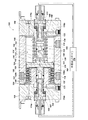
図1は、本開示の往復流体ポンプ100の実施形態を示す。いくつかの実施形態では、往復流体ポンプ100が例えば、圧縮ガス(例えば、空気)などの加圧された駆動流体を使用して、例えば、液体(例えば、水、油、酸など)、気体、または粉末状物質などの対象流体を送り出されるように構成される。したがって、いくつかの実施形態では、往復流体ポンプ100が空気圧作動式流体ポンプを含むことができる。
FIG. 1 shows an embodiment of a reciprocating
往復流体ポンプ100は、ポンプ本体102を形成するように一緒に組み立てることができる2つ以上の構成要素を含むことができるポンプ本体102を含む。例えば、ポンプ本体102は、中央本体部104と、中央本体部104の第1の側に取り付けることができる第1の端部106と、中央本体部104の反対側の第2の側に取り付けることができる第2の端部108とを含むことができる。
Reciprocating
往復流体ポンプ100はまた、対象流体入口114および対象流体出口116を含んでもよい。往復流体ポンプ100の動作中、往復流体ポンプ100は対象流体入口114を介して対象流体を往復流体ポンプ100内に引き込むことができ、対象流体出口116を介して対象流体を往復流体ポンプ100から排出することができる。
Reciprocating
図2は、図1の往復流体ポンプ100の概略、上面断面図である。往復流体ポンプ100は、第1のプランジャ120と、第2のプランジャ122と、第1のピストンチャンバ144と、第2のピストンチャンバ146と、第1のピストン140と、第2のピストン142と、第1のセンサアセンブリ109と、第2のセンサアセンブリ111とを含む。ポンプ本体102はキャビティ110を内部に含むことができる(例えば、収容することができる)。第1のプランジャ120及び第2のプランジャ122は、キャビティ110内に配置することができる。第1および第2のプランジャ120、122はそれぞれ、可撓性ポリマー材料(例えば、熱硬化性材料または熱可塑性材料)から形成され、それを含むことができる。以下でさらに詳細に説明するように、第1および第2のプランジャ120、122の各々は例えば、ダイヤフラムおよび/またはベローズ(図に示す)を含むことができる。さらに、第1および第2のプランジャ120、122は、往復流体ポンプ100が駆動されたときに(すなわち、図2に示す図から左右の水平方向に)、キャビティ110内で長手方向に膨張および圧縮することができる。
FIG. 2 is a schematic, cross-sectional top view of the reciprocating
第1および第2のプランジャ120、122はキャビティ110を、第1および第2のプランジャ120、122の外部の対象流体チャンバ126と、第1のプランジャ120の内部(例えば、第1のプランジャ120のベローズ内)の第1の駆動流体チャンバ127と、第2のプランジャ122の内部(例えば、第2のプランジャ122のベローズ内)の第2の駆動流体チャンバ129とに分割することができる。図2に示すように、第1及び第2のプランジャ120、122は互いに構造的に(例えば、物理的に)接続することができる。その結果、第1および第2のプランジャ120、122の一方の物理的運動は第1および第2のプランジャ120、122の他方のプランジャの運動に物理的に影響を及ぼす(例えば、駆動する)。したがって、第1および第2のプランジャ120、122の動作は以下でさらに詳細に説明するように、外部コントローラ170によって一緒に動作され、制御されるようにできる。
The first and
第1のプランジャ120は第1の外径D1を有することができ、第2のプランジャ122は第2の外径D2を有することができる。第2のプランジャ122の第2の外径D2は、第1のプランジャ120の第1の外径D1よりも小さくすることができる。例えば、いくつかの実施形態では、第1のプランジャ120の第1の外径D1と第2のプランジャ122の第2の外径D2との比が約1.10〜約3.00の範囲内とするのが好ましい。1つまたは複数の実施形態では、第1のプランジャ120の第1の外径D1と第2のプランジャ122の第2の外径D2との比が約1.20とすることができる。追加の実施形態では、第1のプランジャ120の第1の外径D1と第2のプランジャ122の第2の外径D2との比が約2.00とすることができる。さらに、特定の比率が本明細書に記載されているが、当業者は1.00を超える任意の比率(例えば、3.00、5.00、10.00、またはそれ以上)が本開示の範囲内であることを容易に認識するのであろう。
The
いくつかの実施形態では、第1のプランジャ120の第1の外径D1および対象流体チャンバ126の内径が少なくとも実質的に同じであってもよい(例えば、1〜10/100インチ以内)。例えば、第1のプランジャ120の第1の外径D1は第1のプランジャ120が対象流体チャンバ126内に嵌合することを可能にするために、対象流体チャンバ126の内径よりわずかに小さくてもよい。その結果、いくつかの実施形態では、対象流体チャンバ126の内径と第2のプランジャ122の第2の直径D2との比が約1.10〜約3.00の範囲内であってもよい。以下により詳細に論じられるように、往復流体ポンプ100を通る対象流体の流量(例えば、往復流体ポンプ100によって引き起こされる)は、第1のプランジャ120と第2のプランジャ122との間の直径D1、D2のサイズの差に少なくとも部分的に基づいている。
In some embodiments, the first outer diameter D1 of the
1つまたは複数の実施形態では、第1のプランジャ120が第1のヘッド部分136と、第1のプランジャ120の第1のヘッド部分136から延びる第1のベローズ137とを含むことができる。さらに、第2のプランジャ122は、第2のヘッド部分138と、第2のプランジャ122の第2のヘッド部分138から延びる第2のベローズ139とを含むことができる。さらに、第1のプランジャ120の第1のヘッド部分136は第1のプランジャ120の第1のベローズ137と反対側に第1のプランジャ面141を含むことができ、第2のプランジャ122の第2のヘッド部分138は、第2のプランジャ122の第2のベローズ139と反対側に第2のプランジャ面143を含むことができる。
In one or more embodiments, the
動作の方向において、対象流体チャンバ126内に配置されると、第1のプランジャ120の第1のプランジャ面141は、第2のプランジャ122の第2のプランジャ面143に面することができる。さらに、いくつかの実施形態では、第1のプランジャ120の第1のプランジャ面141が第2のプランジャ122の第2のプランジャ面143と物理的に接触してもよい。さらに、いくつかの例では、第1のプランジャ120の第1のヘッド部分136の一部分が第2のプランジャ122の第2のヘッド部分138の一部分にねじ込まれてもよく、またはその逆であってもよい。追加の実施形態では、第1のプランジャ120の第1のヘッド部分136および第2のプランジャ122の第2のヘッド部分138が単一の一体型本体であってもよい。さらに、1つまたは複数の実施形態では、第1のプランジャ120および第2のプランジャ122が単一の一体型本体であってもよい。
In the direction of operation, when disposed within the
第1のプランジャ120の周縁123をポンプ本体102に取り付けることができ、ポンプ本体102と第1のプランジャ120との間に流体密封シールを設けることができる。同様に、第2のプランジャ122の周縁125をポンプ本体102に取り付けることができ、ポンプ本体102と第2のプランジャ122との間に流体密封シールを設けることができる。
The
さらに図2を参照すると、ポンプ本体102は対象流体入口114からポンプ本体102を通って対象流体チャンバ126に通じる対象流体入口経路130を含むことができ、ポンプ本体102は、対象流体チャンバ126からポンプ本体102を通って対象流体出口116に通じる対象流体出口経路134を含むことができる。したがって、対象流体は単一の流体源から対象流体入口114を介して往復流体ポンプ100内に引き込まれてもよく、対象流体は対象流体出口116を介して往復流体ポンプ100から放出されてもよい。いくつかの実施形態では、対象流体入口経路130が2つ以上の対象流体入口経路130a、130bを含むことができる。
Still referring to FIG. 2, the
さらに、往復流体ポンプ100は、対象流体入口経路130および対象流体出口経路134内に配置された1つまたは複数の対象流体入口逆止弁および1つまたは複数の対象流体出口逆止弁を含むことができる。例えば、対象流体入口逆止弁は流体が対象流体入口経路130を通って対象流体チャンバ126に流入することができるが、対象流体入口経路130を通って対象流体チャンバ126から流出することができないことを保証するために、対象流体入口経路130に近接して設けられてもよい。対象流体出口逆止弁は流体が対象流体出口経路134を通って対象流体チャンバ126から流出することができるが、第1の対象流体出口経路134を通って対象流体チャンバ126に流入することができないことを確実にするために、対象流体出口経路134に近接して設けることができる。逆止弁は例えば、ボール逆止弁、ダイヤフラム逆止弁、電磁逆止弁など、一方向の流れを可能にし、反対方向の流れを制限する任意の適切な弁を含むことができる。例えば、2014年4月25日に出願されたSimmonsの米国特許出願第14/262,146号(US 2014/0334957 A1)に記載されているボール逆止弁のうちの1つまたは複数を含むことができ、その開示全体が参照により本明細書に組み込まれる。
Further, the reciprocating
さらに図2を参照すると、第1のピストン140は、第1のピストンヘッド148および第1のシャフト150を含むことができる。第2のピストン142は、第2のピストンヘッド152および第2のシャフト154を含むことができる。第1のシャフト150は、第1のピストンヘッド148から1つの長手方向端部に延びてもよく、第2の反対側の長手方向端部で第1のプランジャ120に連結されてもよい。第1のシャフト150は第1の駆動流体チャンバ127に面する(すなわち、第1のプランジャ面141の反対側の)第1のプランジャ120の側面に連結されてもよい。例えば、第1のシャフト150は第1のピストンヘッド148から第1のプランジャ120内に(例えば、第1のプランジャ120のベローズを通って)延びることができる。
With further reference to FIG. 2, the
さらに、第2のシャフト154は第2のピストンヘッド152から1つの長手方向端部に延びることができ、反対側の長手方向端部で第2のプランジャ122に連結することができる。第2のシャフト154は第2の駆動流体チャンバ129に面する(すなわち、第2のプランジャ面143の反対側の)第2のプランジャ122の側面に連結されてもよい。例えば、第2のシャフト154は第2のピストンヘッド152から第2のプランジャ122内に(例えば、第2のプランジャ122のベローズを通って)延びることができる。
Further, the
第1のセンサアセンブリ109は、往復流体ポンプ100の外部から第1の端部106の内部に延びることができる。第2のセンサアセンブリ111は、往復流体ポンプ100の外部から第2の端部108の内部に延びることができる。以下でより詳細に説明するように、往復流体ポンプ100の外部コントローラ170は、第1および第2のセンサアセンブリ109、111を利用して、往復流体ポンプ100を動作させることができる。
The
いくつかの実施形態では、第1のピストン140の第1のピストンヘッド148が第1のセンサ収容キャビティ164を含むことができる。第1のセンサ収容キャビティ164は、少なくとも部分的に第1のピストンヘッド148を介して延びることができる。さらに、第2のピストン142の第2のシャフト154は、第2のセンサ収容キャビティ166を含むことができる。第2のセンサ収容キャビティ166は、少なくとも部分的に第2のピストンヘッド152を介して延びることができる。第1および第2のセンサ受容キャビティ164、166は、それぞれ第1および第2のセンサアセンブリ109、111の少なくとも一部を受容するような大きさおよび形状であってもよい。
In some embodiments, the
いくつかの実施形態では、第1のセンサアセンブリ109が第1のセンサ部182および第1のターゲット部184を含むことができる。第1のセンサ部182は、第1のピストンチャンバ144内に配置され、第1のピストンチャンバ144を介して延びることができる。さらに、第1のセンサ部182は、第1のピストン140の第1のシャフト150の第1のセンサ収容キャビティ164内に少なくとも部分的に延びることができる。第1のセンサアセンブリ109の第1のターゲット部184は第1のセンサ受容キャビティ164の基部(すなわち、内側端部)に配置されてもよい。第1のセンサ部182は、第1のターゲット部184に対する第1のセンサ部182の近接を決定するように構成されてもよい。
In some embodiments,
さらに、いくつかの実施形態では、第2のセンサアセンブリ111が第2のセンサ部186および第2のターゲット部188を含むことができる。第2のセンサ部186は第2のピストンチャンバ146内に配置することができ、第2のピストンチャンバ146を介して延びることができる。さらに、第2のセンサ部186は、第2のピストン142の第2のシャフト154の第2のセンサ受容キャビティ166内に少なくとも部分的に延びることができる。第2のセンサアセンブリ111の第2のターゲット部188は第1のセンサ受容キャビティ164の基部(すなわち、内側端部)内に配置されてもよい。第2のセンサ部186は、第2のターゲット部188に対する第2のセンサ部186の近接を決定するように構成されてもよい。
Further, in some embodiments, the
いくつかの実施形態では第1および第2のセンサアセンブリ109、111は磁気近接センサおよびターゲットを含むことができる。追加の実施形態では第1および第2のセンサアセンブリ109、111は誘導近接センサおよびターゲットを含むことができる。さらなる実施形態では第1および第2のセンサアセンブリ109、111は光近接センサおよびターゲットを含むことができる。
In some embodiments, the first and
さらに図2を参照すると、いくつかの実施形態では、第1の端部106が第1の端部106の壁を通って延びる1つまたは複数の第1の駆動流体入口174a、174bを含むことができる。1つまたは複数の第1の駆動流体入口174a、174bは、第1の駆動流体チャンバ127(第1のプランジャ120のベローズ内の駆動流体チャンバ)および第1のピストンチャンバ144への駆動流体流路を提供することができる。さらに、場合によっては1つまたは複数の第1の駆動流体入口174a、174bは第1のピストンチャンバ144のための駆動流体出口として働くことができる。さらに、1つまたは複数の第1の駆動流体入口174a、174bはそれぞれ、往復流体ポンプ100の特定の動作中に少なくとも1つの方向への流体の流れを制限することができる少なくとも1つの弁(例えば、逆止弁)を含むことができる。
Still referring to FIG. 2, in some embodiments, the
さらに、第2の端部108は、第2の端部108の壁を通って延びる1つまたは複数の第2の駆動流体入口178a、178bを含むことができる。1つまたは複数の第2の駆動流体入口178a、178bは、第2の駆動流体チャンバ129(第2のプランジャ122のベローズ内の駆動流体チャンバ)および第2のピストンチャンバ146への駆動流体流路を提供することができる。さらに、場合によっては1つまたは複数の第2の駆動流体入口178a、178bは第2のピストンチャンバ146のための駆動流体出口として働くことができる。さらに、1つまたは複数の第2の駆動流体入口178a、178bはそれぞれ、往復流体ポンプ100の特定の動作中に少なくとも1つの方向への流体の流れを制限することができる少なくとも1つの弁(例えば、逆止弁)を含むことができる。
Further, the
動作中に、第1のプランジャ120は図2の状態から右方向に膨張し、左方向に圧縮することができる。同様に、第2のプランジャ122は図2の状態から、左方向に膨張し、右方向に圧縮することができる。換言すれば、第1及び第2のプランジャ120、122は、作動中に圧縮及び膨張ストロークを繰り返すことができる。
In operation, the
第1のプランジャ120が膨張し(すなわち、膨張行程を通って移動し)、第2のプランジャ122が圧縮し(すなわち、圧縮行程を通って移動し)、第1の駆動流体チャンバ127の容積が増加し、対象流体チャンバ126の容積が減少し、第2の駆動流体チャンバ129の容積が減少する。その結果、対象流体は、対象流体出口経路134を介して対象流体チャンバ126から放出され得る。第1のプランジャ120は、第1の駆動流体チャンバ127内に加圧された駆動流体を提供することによって、少なくとも部分的に延ばすことができる。さらに、第2のプランジャ122は、膨張する第1のプランジャ120によって圧縮されると共に、第2のピストンチャンバ146および第2の駆動流体チャンバ129で排気するようにしてもよい。
The
逆に、第2のプランジャ122が膨張し(すなわち、膨張行程を通って移動し)、第1のプランジャ120が圧縮し(すなわち、圧縮行程を通って移動し)、第2の駆動流体チャンバ129の容積が増加し、対象流体チャンバ126の容積が増加し、第1の駆動流体チャンバ127の容積が減少する。その結果、対象流体は、対象流体入口経路130を介して対象流体チャンバ126内に引き込まれ得る。第2のプランジャ122は膨張されてもよく、そして第1のプランジャ120は第2のプランジャ122によって少なくとも部分的に圧縮されると共に第1のピストンチャンバ144および第1の駆動流体チャンバ127で排気するようにしてもよい。以下でより詳細に説明するように、第1および第2のプランジャ120、122の圧縮および膨張は、外部コントローラ170によって制御することができる。
Conversely, the
第1のプランジャ120の膨張ストロークを開始するために、加圧された駆動流体が、往復流体ポンプ100の第1の端部106の第1の駆動流体入口174a、174bのうちの1つ以上を通して流入され得る。例えば、場合によっては、加圧された駆動流体(例えば、空気)を、1つまたは複数の第1の駆動流体入口174a、174bを通して第1の駆動流体チャンバ127内に、および第1のピストンチャンバ144内に流入することができる。その結果、第1の駆動流体チャンバ127および第1のピストンチャンバ144は加圧された駆動流体で加圧され得、これは第1のプランジャ120に膨張ストロークを開始させ得る。言い換えると、第1の駆動流体チャンバ127および第1のピストンチャンバ144を加圧することによって、第1のプランジャ120(および第1のプランジャ120のベローズ)を膨張させることができる。
To initiate the inflation stroke of the
第1のプランジャ120が膨張ストロークで移動するとき、対象流体チャンバ126内の対象流体は、対象流体チャンバ126から対象流体出口経路134を介して、および対象流体出口116を介して放出され得る。
As the
対象流体チャンバ126から対象流体を放出した後、第1のプランジャ120の圧縮ストロークを開始するために、第1の駆動流体チャンバ127および第1のピストンチャンバ144を減圧することができる(例えば、周囲への排気、減圧領域、または真空)。後述するように、第1のプランジャ120は、第2のプランジャ122の膨張ストロークによって圧縮される。第1のプランジャ120が圧縮ストロークで移動すると、対象流体は、対象流体入口経路130を介して対象流体チャンバ126内に引き込まれ得る。
After discharging the target fluid from the
第2のプランジャ122の膨張ストロークを開始するために、加圧された駆動流体が、往復流体ポンプ100の第2の端部108の1つ以上の第2の駆動流体入口178a、178bを介して流入され得る。例えば、いくつかの例では、加圧された駆動流体が1つ以上の第2の駆動流体入口178を介して第2の駆動流体チャンバ129内に、および第2のピストンチャンバ146内に流入されてもよい。その結果、第2の駆動流体チャンバ129および第2のピストンチャンバ146は加圧された駆動流体で加圧され得、これは第2のプランジャ122に膨張ストロークを開始させることができる。言い換えると、第2の駆動流体チャンバ129および第2のピストンチャンバ146を加圧することによって、第2のプランジャ122(および第2のプランジャ122のベローズ)を膨張させることができる。第2のプランジャ122が膨張ストロークで移動すると、対象流体は、対象流体入口経路130を介して対象流体チャンバ126内に引き込むことができる。
To initiate the inflation stroke of the
対象流体を対象流体チャンバ126内に引き込んだ後、第2のプランジャ122の圧縮ストロークを開始するために、第2の駆動流体チャンバ129および第2のピストンチャンバ146を減圧(例えば、周囲への排気、減圧、または真空)することができ、第1のプランジャ120を膨張ストローク(上述)で移動させることができる。第2のプランジャ122が圧縮ストロークを通って移動すると、対象流体は、対象流体チャンバ126から対象流体出口経路134を介して放出することができる。
After drawing the target fluid into the
したがって、往復流体ポンプ100の送り出す動作を駆動するために、第1の駆動流体チャンバ127および第2の駆動流体チャンバ129は交互または周期的な様式で加圧されて、第1のプランジャ120および第2のプランジャ122を、上述のように、ポンプ本体102内で前後に往復運動させ得る(例えば、連続的な膨張ストロークおよび圧縮ストロークで移動させる)。
Accordingly, to drive the pumping operation of the reciprocating
いくつかの実施形態では当業者には理解されるように、往復流体ポンプ100は加圧された駆動流体の流れを第1の駆動流体チャンバ127と第2の駆動流体チャンバ129との間で前後にシフトさせるためのシフト機構を備えることができる。場合により、シフト機構は例えば、第1および第2のピストン140、142、ならびにシャトル弁を備えることができる。例えば、往復流体ポンプ100は2011年9月9日に出願されたシモンス(Simmons)らの米国特許出願第13/228,934号に記載されているようなシャトル弁アセンブリを含むことができ、その開示は、参照によりその全体が本明細書に組み込まれる。
In some embodiments, as will be appreciated by those skilled in the art, the reciprocating
再び図2を参照すると、上述のように、1つ以上の実施形態ではポンプ作用(例えば、第1および第2のプランジャ120、122の膨張および圧縮ストローク)は外部コントローラ170によって作動されてもよい。特に、外部コントローラ170は駆動流体源(例えば、圧縮空気源)に動作可能に連結されてもよく、駆動流体が往復流体ポンプ100内にいつどこに流入されるかを制御してもよい。いくつかの実施形態では、外部コントローラ170がプログラマブルロジックコントローラ(PLC)を含むことができる。例えば、外部コントローラ170は耐久性があり、工程(例えば、流体を送り出す)を制御するように適合されたデジタルコンピュータを含むことができる。いくつかの実施形態では、外部コントローラ170がGALIL(商標)によって製造されたRIO-47100、または当技術分野で知られている任意の他のPLCを含むことができる。
Referring again to FIG. 2, as described above, in one or more embodiments, the pumping action (e.g., the inflation and compression strokes of the first and
1つまたは複数の実施形態では、外部コントローラ170が往復流体ポンプ100の第1のセンサアセンブリ109および第2のセンサアセンブリ111に動作可能に結合することができる。
上述のように、第1のセンサアセンブリ109は往復流体ポンプ100の第1の端部106内に配置されてもよく、第2のセンサアセンブリ111は往復流体ポンプ100の第2の端部108内に配置されてもよい。さらに、上述のように、第1および第2のセンサアセンブリ109、111の第1および第2のセンサ部は、それぞれ第1および第2のターゲット部に対する第1および第2のセンサ部の近接度を決定するように構成されている。
In one or more embodiments, an
As described above, the
第1のターゲット部184に対する第1のセンサ部182の決定された近接性、および第2のターゲット部188に対する第2のセンサ部186の決定された近接性に基づいて、外部コントローラ170は、第1のプランジャ120および第2のプランジャ122の膨張ストロークおよび圧縮ストロークを動作させることができる。例えば、往復流体ポンプ100の送り出す動作中に、外部コントローラ170は、第1および第2のセンサアセンブリ109、111を利用して、第1のプランジャ120および第2のプランジャ122の膨張ストロークおよび圧縮ストロークの終わりを感知することができる。例えば、外部コントローラ170が第1のセンサアセンブリ109の第1のセンサ部182が第1のセンサアセンブリ109の第1のターゲット部184に対して最も近い位置にあることを(第1のセンサアセンブリ109を介して)感知すると、外部コントローラ170は、第1のプランジャ120が圧縮ストロークの終わりにあると判定することができる。
さらに、第1のプランジャ120が圧縮ストロークの終わりにあると判定することに基づいて、外部コントローラ170は第1のプランジャ120の膨張ストロークを開始するために、加圧された駆動流体を第1のピストンチャンバ144および第1の駆動流体チャンバ127に流入させることができる。
Based on the determined proximity of the
Further, based on determining that the
逆に、外部コントローラ170が第1のセンサアセンブリ109の第1のセンサ部182が第1のセンサアセンブリ109の第1のターゲット部184に対して最も少なく近接している(すなわち、最も遠い)位置にあることを(第1のセンサアセンブリ109を介して)感知すると、外部コントローラ170は第1のプランジャ120が膨張ストロークの終わりにあると判定することができ、外部コントローラ170は第1の駆動流体チャンバ127および第1のピストンチャンバ144を減圧させることができ、加圧された駆動流体を第2のピストンチャンバ146に流入させて、第1のプランジャ120の圧縮ストロークを開始させることができる。さらに、外部コントローラ170は、同様の方法で第2のセンサアセンブリ111を利用して、第2のプランジャ122を膨張ストロークおよび圧縮ストロークにわたって移動させてもよい。上記に鑑みて、外部コントローラ170は第1および第2のセンサアセンブリ109、111を利用して、それぞれの弁(例えば、第1および第2の駆動流体入口174、178内の弁)に信号を送って、第1の駆動流体チャンバ127および第2の駆動流体チャンバ129を独立して加圧および通気する(例えば、第1および第2のプランジャ120、122の膨張および圧縮ストロークを引き起こし、制御する)時を決定することができる。
Conversely, the
上述したように、往復流体ポンプ100は第1及び第2のプランジャ120、122のサイズ差(例えば、直径D1、D2の差)に基づいて対象流体を圧送することができる。
特に、対象流体チャンバ126のサイズは第1のプランジャ120と第2のプランジャ122との間のサイズ差に基づいて決定される(例えば、規定される)。その結果、往復流体ポンプ100の各完全なストローク(例えば、各プランジャの膨張および圧縮ストローク)の間に、対象流体が、第1のプランジャ120と第2のプランジャ122との間のサイズ差に基づいて、対象流体チャンバ126にどれだけ吸引され、排出されるかが決定される。例えば、第1および第2のプランジャ120、122が同じサイズに比較的近い場合、対象流体チャンバ126のサイズは比較的小さくなり、往復流体ポンプ100の各ストローク中に送り出される流体の量は比較的小さくなる。さらに、対象流体チャンバ126のサイズは、第1のプランジャ120のサイズと第2のプランジャ122のサイズとの間の差が大きくなるにつれて増大する。したがって、往復流体ポンプ100の各ストローク中に圧送される流体の量は、第1および第2のプランジャ120、122のサイズの差に基づいて選択され得る。
As described above, the reciprocating
In particular, the size of the
さらに図2を参照すると、いくつかの実施形態ではキャビティ110の内径が約3.0インチとすることができ、第2のプランジャ122の第2の直径D2は約1.5インチとすることができる。さらに、第1および第2のプランジャ120、122がキャビティ110内で長手方向に前後に並進することができる距離は、約1.5インチとすることができる。したがって、往復流体ポンプ100の完全なサイクル中に、往復流体ポンプ100は対象流体の約8.0 in3を汲み上げる(例えば、吐出する)ことができる。第1および第2のプランジャ120、122の特定の直径および並進の特定の距離が提供されるが、当業者は第1および第2のプランジャ120、122の直径D1、D2が任意のサイズであってもよく、並進の距離が任意のサイズであってもよいことを容易に認識するのであろう。例えば、第1のプランジャ120の第1の直径D1は約1.0インチ〜約6.0インチの範囲内とすることができ、第2のプランジャ122の第2の直径D2は、約0.5インチ〜約5.5インチの範囲内とすることができる。さらに、並進の距離は、約0.5インチ〜約2.0インチの範囲内であってもよい。
Still referring to FIG. 2, in some embodiments, the inner diameter of the
上記の結果として、本開示の往復流体ポンプ100は、従来の流体ポンプを上回る利点を提供し得る。例えば、本開示の往復流体ポンプ100は少量の対象流体を送り出すために比較的小さなダイヤフラムを利用する従来のポンプとは異なり、比較的大きなプランジャ(例えば、大きなダイアフラム)を利用しながら、往復流体ポンプ100によって比較的少量の対象流体(例えば、マイクロドージング)を送り出すことを可能にすることができる。小さなダイヤフラムを利用すると、ダイヤフラムの耐久性および信頼性が著しく低下する。例えば、小さなダイヤフラムのベローズは、使用中にしばしば故障する。結果として、本開示の往復流体ポンプ100を増加させることは、往復流体ポンプ100の耐久性および信頼性を増加させながら、往復流体ポンプ100によって比較的少量(例えば、少量の流速)の対象流体(例えば、マイクロドージング)を送り出されることを可能にすることができる。
As a result of the above, the reciprocating
図1および図2の往復流体ポンプ100は2つのプランジャを使用するものとして示されているが、本開示の流体ポンプのさらなる実施形態は2つ以上のプランジャを含んでもよい。さらに、いくつかの実施形態では往復流体ポンプ100が単一の一体部品を形成する2つのプランジャを含むことができ、単一の一体部品の各端部の直径は異なるサイズにされる。
Although the reciprocating
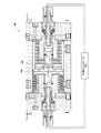
図3は、第1のプランジャ120の第1の外径D1と第2の外径D2との異なる比を有する往復流体ポンプ300の概略、上面断面図を含んでいる。特に、図3の実施例では、第1のプランジャ120の第1の外径D1と第2の外径D2との比は約1.2である。
FIG. 3 includes a schematic, top cross-sectional view of a
図4は、本開示の1つ以上の実施形態による往復流体ポンプ100を形成する方法400のフローチャートを示している。いくつかの実施形態では、方法400がポンプ本体102を形成する動作410を含むことができる。例えば、動作410は、単一の対象流体チャンバ126を有するポンプ本体102を形成することを含むことができる。いくつかの例では、動作410が第1の端部106および第2の端部108を中央本体部104に取り付けることを含むことができる。1つまたは複数の実施形態では、動作410が図1〜3に関して上述した構成のいずれかに従ってポンプ本体102を形成することを含むことができる。
FIG. 4 illustrates a flowchart of a
方法400は、第1のプランジャ120を単一の対象流体チャンバ126内に配置する動作420をさらに含むことができる。例えば、動作420は単一の対象流体チャンバ126内に第1のプランジャ120を配置することを含むことができ、第1のプランジャ120は、第1の直径D1を有する。いくつかの実施形態では、動作420が単一の対象流体チャンバ126内に第1のヘッド部分136および第1のベローズ137を有する第1のプランジャ120を配置することを含むことができる。
The
さらに、方法400は、単一の対象流体チャンバ126内に第2のプランジャ122を配置する動作430を含むことができる。例えば、動作430は単一の対象流体チャンバ126内に第2のプランジャ122を配置することを含むことができ、第2のプランジャ122は第1の直径D1よりも小さい異なる第2の直径D2を有する。いくつかの実施形態では、動作430が単一の対象流体チャンバ126内に第2のヘッド部分138および第2のベローズ139を有する第2のプランジャ122を配置することを含むことができる。1つまたは複数の実施形態では、動作420および430がポンプ本体102のキャビティ110を、第1および第2のプランジャ120、122の外部上の対象流体チャンバ126、第1のプランジャ120の内部(例えば、第1のプランジャ120のベローズ内)上の第1の駆動流体チャンバ127、および第2のプランジャ122の内部(例えば、第2のプランジャ122のベローズ内)上の第2の駆動流体チャンバ129に分割することを含むことができる。さらに、動作420および430は、図2および図3に関して上述した構成のいずれかに従って、対象流体チャンバ126内に第1および第2のプランジャ120、122を配置することを含むことができる。
Further, the
さらに、方法400は、第1のプランジャ120を第2のプランジャ122に構造的に接続する動作440を含むことができる。例えば、動作440は、第1のプランジャ120の一部を第2のプランジャ122の一部にねじ込むことを含むことができる。さらに、動作440は任意の適切な方法(例えば、第1および第2のプランジャ120、122を一体的に形成する接着剤、締結具)に従って、第1および第2のプランジャ120、122を構造的に接続することを含んでもよい。さらに、動作440は、図2および図3に関して上述した構成のいずれかに従って第1および第2のプランジャ122を接続することを含むことができる。
Further, the
いくつかの実施形態では、方法400が第1のプランジャ120の第1の直径D1と第2のプランジャ122の第2の直径D2との比が約1.10〜約3.00の範囲内にあるように、第1のプランジャ120および第2のプランジャ122を選択することをさらに含むことができる。追加の実施形態では、方法400が約1.20の比を有するように第1のプランジャ120および第2のプランジャ122の直径D1、D2を選択することを含むことができる。さらなる実施形態では、方法400が約2.00の比を有するように第1のプランジャ120および第2のプランジャ122の直径D1、D2を選択することを含むことができる。
In some embodiments, the
上述し、添付図面に示した本開示の実施形態は本開示の範囲を限定するものではなく、本開示の範囲は添付の特許請求の範囲およびそれらの法的均等物の範囲によって包含される。任意の同等の実施形態は、本開示の範囲内である。実際、本明細書に示され、説明されたものに加えて、説明された要素の代替の有用な組合せなど、開示の様々な修正が、説明から当業者に明らかになるのであろう。そのような修正および実施形態もまた、添付の特許請求の範囲および均等物の範囲内にある。 The embodiments of the present disclosure described above and illustrated in the accompanying drawings do not limit the scope of the present disclosure, which is encompassed by the appended claims and their legal equivalents. Any equivalent embodiments are within the scope of the present disclosure. Indeed, various modifications of the disclosure, in addition to those shown and described herein, as well as alternative useful combinations of the described elements, will be apparent to those skilled in the art from the description. Such modifications and embodiments are also within the scope of the appended claims and equivalents.
100 往復流体ポンプ
102 ポンプ本体
104 中央本体部
106 第1の端部
108 第2の端部
110 キャビティ
114 対象流体入口
116 対象流体出口
120 第1のプランジャ
122 第2のプランジャ
126 対象流体チャンバ
140 第1のピストン
142 第2のピストン
144 第1のピストンチャンバ
146 第2のピストンチャンバ
170 外部コントローラ
D1 第1のプランジャ120の第1の外径
D2 第2のプランジャ122の第2の外径
100 reciprocating fluid pump
102 Pump body
104 Central body
106 first end
108 Second end
110 cavities
114 Target fluid inlet
116 Target fluid outlet
120 1st plunger
122 Second plunger
126 Target fluid chamber
140 1st piston
142 Second piston
144 1st piston chamber
146 Second piston chamber
170 External controller
D1 first outer diameter of
D2 Second outer diameter of
Claims (20)
ポンプ本体と、
前記ポンプ本体内の対象流体チャンバと、
前記ポンプ本体の前記対象流体チャンバ内に配置され、第1のヘッド部と前記第1のヘッド部から延在する第1のベローズとを有する第1のプランジャを含み、
前記第1のプランジャは往復運動で膨張および圧縮して前記ポンプ本体内の前記対象流体チャンバを介して前記対象流体を送り出すように構成されると共に、前記第1のヘッド部および前記第1のベローズは第1の断面寸法を有しており、
更に、前記ポンプ本体の前記対象流体チャンバ内に配置され、第2のヘッド部と前記第2のヘッド部から延在する第2のベローズとを有する第2のプランジャを含み、
前記第2のプランジャは往復運動で膨張および圧縮して前記ポンプ本体内の前記対象流体チャンバを介して前記対象流体を送り出すように構成され、
前記第2のヘッド部および前記第2のベローズは、前記第1の断面寸法よりも小さい第2の断面寸法を有している、ことを特徴とする往復流体ポンプ。 A reciprocating fluid pump for delivering a target fluid,
The pump body,
A target fluid chamber in the pump body;
A first plunger disposed in the target fluid chamber of the pump body and having a first head portion and a first bellows extending from the first head portion;
The first plunger is configured to expand and compress in a reciprocating motion to pump out the target fluid through the target fluid chamber in the pump body, and the first head portion and the first bellows Has a first cross-sectional dimension,
A second plunger disposed in the target fluid chamber of the pump body, the second plunger having a second head portion and a second bellows extending from the second head portion;
The second plunger is configured to expand and compress in a reciprocating motion to pump out the target fluid through the target fluid chamber in the pump body;
The reciprocating fluid pump, wherein the second head portion and the second bellows have a second cross-sectional dimension smaller than the first cross-sectional dimension.
ポンプ本体と、
前記ポンプ本体内の対象流体チャンバと、
第1の断面寸法を有すると共に、ポンプ本体の対象流体チャンバ内に配置された第1のプランジャとを含み、
前記第1のプランジャは可撓性材料を有すると共に、往復運動で膨張および圧縮して、対象流体をポンプ本体内の対象流体チャンバを介して送り出すように構成されており、
更に、前記第1の断面寸法よりも小さい第2の断面寸法を有すると共に、ポンプ本体の対象流体チャンバ内に配置された第2のプランジャを含み、
前記第2のプランジャは可撓性材料を有すると共に、往復運動で膨張および圧縮して、対象流体を前記ポンプ本体内の前記対象流体チャンバを介して送り出すように構成されており、
前記第1のプランジャが前記第2のプランジャに構造的に接続されている、ことを特徴とする往復流体ポンプ。 A reciprocating fluid pump for delivering a target fluid,
The pump body,
A target fluid chamber in the pump body;
A first plunger having a first cross-sectional dimension and disposed within a target fluid chamber of the pump body;
The first plunger has a flexible material and is configured to expand and compress in a reciprocating motion to pump a target fluid through a target fluid chamber in a pump body.
And a second plunger having a second cross-sectional dimension smaller than the first cross-sectional dimension and disposed within the target fluid chamber of the pump body.
The second plunger has a flexible material and is configured to expand and compress in a reciprocating motion to pump a target fluid through the target fluid chamber in the pump body.
A reciprocating fluid pump, wherein the first plunger is structurally connected to the second plunger.
前記第2のプランジャの前記第2のベローズ内に少なくとも部分的に形成された第2のピストンチャンバと、
前記第1のプランジャに連結され、前記第1のピストンチャンバ内に少なくとも部分的に配置された第1のピストンと、
前記第2のプランジャに連結され、前記第2のピストンチャンバ内に少なくとも部分的に配置された第2のピストンとを含む、ことを特徴とする請求項12に記載の往復流体ポンプ。 A first piston chamber at least partially formed in the first bellows of the first plunger;
A second piston chamber at least partially formed within the second bellows of the second plunger;
A first piston coupled to the first plunger and at least partially disposed within the first piston chamber;
13. A reciprocating fluid pump according to claim 12, comprising a second piston coupled to said second plunger and at least partially disposed within said second piston chamber.
単一の対象流体チャンバを内部に有するポンプ本体を形成し、
前記単一の対象流体チャンバ内に第1のプランジャを配置すると共に、前記第1のプランジャは第1の断面寸法を有し、
前記単一の対象流体チャンバ内に第2のプランジャを配置すると共に、前記第2のプランジャは、第1の断面寸法よりも小さい第2の異なる断面寸法を有し、そして、
前記第1のプランジャを前記第2のプランジャに構造的に接続する、ことを特徴とする方法。 A method of forming a reciprocating fluid pump, comprising:
Forming a pump body having a single target fluid chamber therein;
Disposing a first plunger within the single target fluid chamber, wherein the first plunger has a first cross-sectional dimension;
Disposing a second plunger within the single target fluid chamber, wherein the second plunger has a second different cross-sectional dimension smaller than the first cross-sectional dimension; and
The method of claim 1, wherein the first plunger is structurally connected to the second plunger.
Applications Claiming Priority (2)
| Application Number | Priority Date | Filing Date | Title |
|---|---|---|---|
| US16/011,015 US10890172B2 (en) | 2018-06-18 | 2018-06-18 | Fluid pumps and related systems and methods |
| US16/011,015 | 2018-06-18 |
Publications (3)
| Publication Number | Publication Date |
|---|---|
| JP2020002949A true JP2020002949A (en) | 2020-01-09 |
| JP2020002949A5 JP2020002949A5 (en) | 2022-06-03 |
| JP7388829B2 JP7388829B2 (en) | 2023-11-29 |
Family
ID=68839728
Family Applications (1)
| Application Number | Title | Priority Date | Filing Date |
|---|---|---|---|
| JP2019111972A Active JP7388829B2 (en) | 2018-06-18 | 2019-06-17 | Fluid pumps, related systems and methods |
Country Status (5)
| Country | Link |
|---|---|
| US (2) | US10890172B2 (en) |
| JP (1) | JP7388829B2 (en) |
| KR (1) | KR102674580B1 (en) |
| CN (1) | CN110617200B (en) |
| TW (1) | TWI856963B (en) |
Cited By (1)
| Publication number | Priority date | Publication date | Assignee | Title |
|---|---|---|---|---|
| JP2024527393A (en) * | 2021-07-14 | 2024-07-24 | ハイダック テクノロジー ゲゼルシャフト ミット ベシュレンクテル ハフツング | Conveying device having bellows and cooling device |
Families Citing this family (3)
| Publication number | Priority date | Publication date | Assignee | Title |
|---|---|---|---|---|
| NO20171099A1 (en) * | 2017-07-04 | 2019-01-07 | Rsm Imagineering As | Pressure transfer device and associated system, fleet and use, for pumping high volumes of fluids with particles at high pressures |
| US10890172B2 (en) * | 2018-06-18 | 2021-01-12 | White Knight Fluid Handling Inc. | Fluid pumps and related systems and methods |
| US12392336B2 (en) * | 2023-03-15 | 2025-08-19 | Westinghouse Electric Company Llc | Bellows pump for liquid metals |
Citations (3)
| Publication number | Priority date | Publication date | Assignee | Title |
|---|---|---|---|---|
| US2613607A (en) * | 1949-10-27 | 1952-10-14 | Milton Roy Co | Bellows pump |
| JPS608485A (en) * | 1983-06-28 | 1985-01-17 | Konan Denki Kk | Positive displacement pump |
| US5558506A (en) * | 1994-03-03 | 1996-09-24 | Simmons; John M. | Pneumatically shifted reciprocating pump |
Family Cites Families (31)
| Publication number | Priority date | Publication date | Assignee | Title |
|---|---|---|---|---|
| US2464095A (en) * | 1945-02-07 | 1949-03-08 | William L Nies | Pump |
| US2578265A (en) * | 1948-10-11 | 1951-12-11 | Milton Roy Co | Bellows pump |
| US2613610A (en) * | 1949-02-04 | 1952-10-14 | Milton Roy Co | Differential bellows pump |
| US2951450A (en) * | 1956-04-17 | 1960-09-06 | John C Fisher | Fluid pump |
| US5141412A (en) * | 1988-10-06 | 1992-08-25 | Meinz Hans W | Double acting bellows-type pump |
| US5224841A (en) * | 1992-04-24 | 1993-07-06 | Semitool, Inc. | Pneumatic bellows pump with supported bellows tube |
| US5480292A (en) * | 1993-05-19 | 1996-01-02 | Asti Sae | Dual chamber pump |
| US6079959A (en) * | 1996-07-15 | 2000-06-27 | Saint-Gobain Performance Plastics Corporation | Reciprocating pump |
| JP3554115B2 (en) * | 1996-08-26 | 2004-08-18 | 株式会社コガネイ | Chemical supply device |
| US5863186A (en) * | 1996-10-15 | 1999-01-26 | Green; John S. | Method for compressing gases using a multi-stage hydraulically-driven compressor |
| TW550632B (en) | 2001-11-23 | 2003-09-01 | Koganei Ltd | Chemical feed system |
| JP3989334B2 (en) * | 2002-08-23 | 2007-10-10 | 株式会社イワキ | Double reciprocating bellows pump |
| US6851935B2 (en) * | 2003-01-23 | 2005-02-08 | Baker Hughes Incorporated | Above the motor bellows expansion member for a submersible pump |
| TWI253359B (en) | 2003-03-14 | 2006-04-21 | Dainippon Screen Mfg | Substrate processing device and liquid feeding device |
| JP4603925B2 (en) * | 2005-04-13 | 2010-12-22 | 株式会社コガネイ | Chemical supply device |
| JP4644697B2 (en) * | 2007-06-06 | 2011-03-02 | 日本ピラー工業株式会社 | Reciprocating pump |
| JP5217038B2 (en) | 2007-08-23 | 2013-06-19 | イーグル工業株式会社 | Control valve |
| US9518577B2 (en) * | 2008-06-27 | 2016-12-13 | Lynntech, Inc. | Apparatus for pumping a fluid |
| US8636484B2 (en) * | 2009-01-09 | 2014-01-28 | Tom M. Simmons | Bellows plungers having one or more helically extending features, pumps including such bellows plungers, and related methods |
| DE102009007657A1 (en) * | 2009-02-05 | 2010-08-12 | Wabco Gmbh | Piston-cylinder arrangement with integrated measuring device |
| US8550794B2 (en) * | 2010-08-09 | 2013-10-08 | Foothill Land, Llc | Double acting fluid pump |
| US8622720B2 (en) | 2010-09-09 | 2014-01-07 | Tom M. Simmons | Reciprocating fluid pumps including magnets and related methods |
| US8672645B2 (en) * | 2011-09-22 | 2014-03-18 | Dino Technology Co., Ltd. | Separation type pneumatic dual partition membrane pump and external pneumatic control valve thereof |
| JP6008485B2 (en) | 2011-09-30 | 2016-10-19 | ユニ・チャーム株式会社 | Absorbent articles |
| CN102720649A (en) * | 2012-06-27 | 2012-10-10 | 合肥华升泵阀有限责任公司 | Diaphragm metering pump |
| DE112014002350B4 (en) | 2013-05-10 | 2023-07-06 | White Knight Fluid Handling Inc. (n.d.Ges.d. Staates Minnesota) | Pneumatic fluid reciprocating pump with improved check valve assembly and related methods |
| WO2016021350A1 (en) | 2014-08-08 | 2016-02-11 | 日本ピラー工業株式会社 | Bellows pump device |
| JP6367645B2 (en) | 2014-08-08 | 2018-08-01 | 日本ピラー工業株式会社 | Bellows pump device |
| US20180087181A1 (en) * | 2016-09-29 | 2018-03-29 | Corner Star Limited | Expansion bellows with self-aligned guide rods |
| WO2018143426A1 (en) * | 2017-02-03 | 2018-08-09 | イーグル工業株式会社 | Liquid supply system |
| US10890172B2 (en) * | 2018-06-18 | 2021-01-12 | White Knight Fluid Handling Inc. | Fluid pumps and related systems and methods |
-
2018
- 2018-06-18 US US16/011,015 patent/US10890172B2/en active Active
-
2019
- 2019-06-17 JP JP2019111972A patent/JP7388829B2/en active Active
- 2019-06-17 KR KR1020190071646A patent/KR102674580B1/en active Active
- 2019-06-18 CN CN201910526402.8A patent/CN110617200B/en active Active
- 2019-06-18 TW TW108121037A patent/TWI856963B/en active
-
2021
- 2021-01-12 US US17/146,807 patent/US12071946B2/en active Active
Patent Citations (3)
| Publication number | Priority date | Publication date | Assignee | Title |
|---|---|---|---|---|
| US2613607A (en) * | 1949-10-27 | 1952-10-14 | Milton Roy Co | Bellows pump |
| JPS608485A (en) * | 1983-06-28 | 1985-01-17 | Konan Denki Kk | Positive displacement pump |
| US5558506A (en) * | 1994-03-03 | 1996-09-24 | Simmons; John M. | Pneumatically shifted reciprocating pump |
Cited By (1)
| Publication number | Priority date | Publication date | Assignee | Title |
|---|---|---|---|---|
| JP2024527393A (en) * | 2021-07-14 | 2024-07-24 | ハイダック テクノロジー ゲゼルシャフト ミット ベシュレンクテル ハフツング | Conveying device having bellows and cooling device |
Also Published As
| Publication number | Publication date |
|---|---|
| CN110617200B (en) | 2023-03-17 |
| CN110617200A (en) | 2019-12-27 |
| US20190383280A1 (en) | 2019-12-19 |
| US10890172B2 (en) | 2021-01-12 |
| US12071946B2 (en) | 2024-08-27 |
| KR20190142740A (en) | 2019-12-27 |
| JP7388829B2 (en) | 2023-11-29 |
| TWI856963B (en) | 2024-10-01 |
| KR102674580B1 (en) | 2024-06-13 |
| TW202020594A (en) | 2020-06-01 |
| US20210131418A1 (en) | 2021-05-06 |
Similar Documents
| Publication | Publication Date | Title |
|---|---|---|
| US12071946B2 (en) | Fluid pump with dual plungers and related systems and methods | |
| US20190383279A1 (en) | Fluid pumps and related systems and methods | |
| US7452166B2 (en) | Device for conveying coating powder and method for conveying powder with the conveying device | |
| US9726160B2 (en) | Double acting fluid pump with spring biased piston | |
| JP6157581B2 (en) | Reciprocating pump and related methods | |
| JP4658060B2 (en) | Membrane pump | |
| JP7118581B2 (en) | double diaphragm pump | |
| JP4324568B2 (en) | Bellows pump | |
| RU2006141599A (en) | HYDRAULIC MULTI-CYLINDER PUMP | |
| CN100588839C (en) | fluid driven pump | |
| US7165951B2 (en) | High-pressure generating device | |
| JP5248267B2 (en) | pump | |
| US6345962B1 (en) | Fluid operated pump | |
| WO2019150364A1 (en) | Borehole pump and method of using the same | |
| JP2003003966A (en) | High pressure generator | |
| CN105723091A (en) | High-pressure to low-pressure changeover valve for a positive displacement pump | |
| US4281687A (en) | Fluid storage device | |
| CN100538314C (en) | Diaphragm pump | |
| CN112460013B (en) | Hydraulic plunger pump and hydraulic end thereof | |
| JP7541919B2 (en) | Fluid dispenser with zero displacement seal - Patents.com | |
| KR101313551B1 (en) | Hermetic type compressor | |
| JP3568866B2 (en) | Reciprocating pump | |
| CN104295473A (en) | Hydraulic positive displacement pump | |
| RU2086807C1 (en) | Pneumatically-driven diaphragm pump | |
| RU2010141487A (en) | HYDRAULIC DIAGRAM PUMP |
Legal Events
| Date | Code | Title | Description |
|---|---|---|---|
| A521 | Request for written amendment filed |
Free format text: JAPANESE INTERMEDIATE CODE: A523 Effective date: 20220526 |
|
| A621 | Written request for application examination |
Free format text: JAPANESE INTERMEDIATE CODE: A621 Effective date: 20220526 |
|
| A131 | Notification of reasons for refusal |
Free format text: JAPANESE INTERMEDIATE CODE: A131 Effective date: 20230315 |
|
| A977 | Report on retrieval |
Free format text: JAPANESE INTERMEDIATE CODE: A971007 Effective date: 20230320 |
|
| A601 | Written request for extension of time |
Free format text: JAPANESE INTERMEDIATE CODE: A601 Effective date: 20230614 |
|
| A521 | Request for written amendment filed |
Free format text: JAPANESE INTERMEDIATE CODE: A523 Effective date: 20230711 |
|
| TRDD | Decision of grant or rejection written | ||
| A01 | Written decision to grant a patent or to grant a registration (utility model) |
Free format text: JAPANESE INTERMEDIATE CODE: A01 Effective date: 20231025 |
|
| A61 | First payment of annual fees (during grant procedure) |
Free format text: JAPANESE INTERMEDIATE CODE: A61 Effective date: 20231116 |
|
| R150 | Certificate of patent or registration of utility model |
Ref document number: 7388829 Country of ref document: JP Free format text: JAPANESE INTERMEDIATE CODE: R150 |