JP2020002955A - Temperature responsive valve with cleaning means - Google Patents
Temperature responsive valve with cleaning means Download PDFInfo
- Publication number
- JP2020002955A JP2020002955A JP2018119632A JP2018119632A JP2020002955A JP 2020002955 A JP2020002955 A JP 2020002955A JP 2018119632 A JP2018119632 A JP 2018119632A JP 2018119632 A JP2018119632 A JP 2018119632A JP 2020002955 A JP2020002955 A JP 2020002955A
- Authority
- JP
- Japan
- Prior art keywords
- valve
- temperature
- chamber
- downstream
- drain
- Prior art date
- Legal status (The legal status is an assumption and is not a legal conclusion. Google has not performed a legal analysis and makes no representation as to the accuracy of the status listed.)
- Granted
Links
Images
Landscapes
- Temperature-Responsive Valves (AREA)
- Details Of Valves (AREA)
Abstract
【課題】 簡易な構成を備え、かつドレン等の流体の漏れを生じさせることなく弁口(弁孔)の下流側の異物を確実に除去することができるクリーニング手段を有する温度応動弁の提供。【解決手段】 弁口62の下流に位置する弁座下流室63内に付着した異物を、調整棒35の螺入操作によって下流刃8で除去してクリーニングを行う。すなわち、調整棒35の操作用溝35cにドライバー等の工具を嵌め入れ、調整棒35を緩めれば、連結棒10aを介して弁軸10自体が回転しながら矢印105方向に上昇し、弁体2及び中心棒4を介して、下流刃8が弁座下流室63の内面に近接して回転する。これによって、下流刃8で弁座下流室63の内面に付着した異物をそぎ落とす。【選択図】図1PROBLEM TO BE SOLVED: To provide a temperature-responsive valve having a simple structure and having a cleaning means capable of reliably removing foreign matter on the downstream side of a valve port (valve hole) without causing a fluid leakage such as a drain. SOLUTION: Foreign matter adhering to the valve seat downstream chamber 63 located downstream of a valve opening 62 is removed by a downstream blade 8 by a screwing operation of an adjusting rod 35 to perform cleaning. That is, if a tool such as a screwdriver is fitted into the operating groove 35c of the adjusting rod 35 and the adjusting rod 35 is loosened, the valve shaft 10 itself rotates and rises in the direction of arrow 105 via the connecting rod 10a, and the valve body The downstream blade 8 rotates close to the inner surface of the valve seat downstream chamber 63 via 2 and the central rod 4. As a result, the downstream blade 8 scrapes off the foreign matter adhering to the inner surface of the valve seat downstream chamber 63. [Selection diagram] Fig. 1
Description
本願に係るクリーニング手段を有する温度応動弁は、温調トラップ等の温度応動弁の内部に付着した異物のクリーニング技術に関する。 The temperature responsive valve having the cleaning means according to the present application relates to a technique for cleaning foreign matter adhered inside a temperature responsive valve such as a temperature control trap.
産業プラントには、ボイラーで生成された高温の蒸気を供給先に向けて移送する配管系統が設置されており、この配管内には蒸気からドレン(凝縮水)が発生する。蒸気を移送する主管にはドレン回収用の支管が接続されており、この支管の末端に設置されたスチームトラップによって、ドレンは不要物として排出されることが多い。 In an industrial plant, a piping system for transferring high-temperature steam generated by a boiler toward a supply destination is installed, and drain (condensed water) is generated from the steam in the piping. A branch pipe for drain recovery is connected to the main pipe for transferring the steam, and the drain is often discharged as unnecessary matter by a steam trap installed at the end of the branch pipe.
しかし、支管内でこのドレンをあえて滞留させ、支管の温度を所定の設定温度に調整して利用するために、温度応動弁としての温調トラップが用いられることがある。たとえば、輸送管を通じ、重油等の高粘性流体を輸送する際、温度が低下すれば重油等が凝固してしまう不都合が生じる。このため、高温の蒸気やドレンが流れる支管を輸送管に沿わせてトレース伝熱管として機能させ、重油等の輸送管と熱交換させることで重油等の温度を高め凝固を防止する。 However, a temperature control trap as a temperature responsive valve may be used in order to intentionally retain the drain in the branch pipe and to adjust and use the temperature of the branch pipe to a predetermined set temperature. For example, when a high-viscosity fluid such as heavy oil is transported through a transport pipe, there is a disadvantage that the heavy oil or the like solidifies if the temperature decreases. For this reason, the branch pipe through which high-temperature steam or drain flows flows along the transport pipe to function as a trace heat transfer pipe, and exchanges heat with the transport pipe of heavy oil or the like to increase the temperature of heavy oil or the like and prevent solidification.
ここで、たとえば重油の場合、輸送のためには40度程度の温度で十分であるが、蒸気の温度は100度以上あるため、蒸気をそのままトレース伝熱管の熱源として用いると重油の温度が上がりすぎる危険がある。このため、トレース伝熱管の末端に温調トラップを設け、トレース伝熱管の温度を適正な設定温度に調整する。 Here, for example, in the case of heavy oil, a temperature of about 40 degrees is sufficient for transportation, but since the temperature of steam is 100 degrees or more, if steam is used as it is as a heat source of the trace heat transfer tube, the temperature of heavy oil rises There is too much danger. Therefore, a temperature control trap is provided at the end of the trace heat transfer tube, and the temperature of the trace heat transfer tube is adjusted to an appropriate set temperature.
トレース伝熱管の末端に設けられた温調トラップには、その内部にトレース伝熱管から蒸気やドレンが流入する弁室が形成されており、弁室の下方にはさらに排出室が形成されている。そして、弁室と排出室とは小径の弁口によって接続されており、弁室側を上流、排出室側を下流として、弁口を通じて蒸気やドレンが流れる。 In the temperature control trap provided at the end of the trace heat transfer tube, a valve chamber into which steam or drain flows from the trace heat transfer tube is formed, and a discharge chamber is further formed below the valve chamber. . The valve chamber and the discharge chamber are connected by a small-diameter valve port, and steam and drain flow through the valve port with the valve chamber side being upstream and the discharge chamber side being downstream.
弁室内には、先端に弁体が設けられている弁軸が配置されている。そして、この先端の弁体は弁口に向けて位置しており、弁軸には感温部材であるバイメタル積層体が取り付けられている。 In the valve chamber, a valve shaft provided with a valve body at the tip is disposed. The valve body at the tip is located toward the valve port, and a bimetal laminate as a temperature sensing member is attached to the valve shaft.
弁室内に高温のドレンが流入した場合、この高温に反応してバイメタル積層体が膨張して弁軸を軸方向に移動させ、先端の弁体が弁口を閉じる。この後、加熱対象との熱交換によってドレンの温度が低下すると、この温度低下に反応してバイメタル積層体が収縮し、復帰用バネの伸張に従って弁軸が移動し弁体が弁口を開いて低温のドレンを排出室側に排出する。こうして、弁軸の変位に基づいて弁口の開閉が繰り返され、トレース伝熱管の温度が一定の基準温度に保たれる。 When a high-temperature drain flows into the valve chamber, the bimetal laminate expands in response to the high temperature to move the valve shaft in the axial direction, and the valve body at the tip closes the valve port. Thereafter, when the temperature of the drain decreases due to heat exchange with the object to be heated, the bimetal laminate contracts in response to the temperature decrease, the valve shaft moves according to the extension of the return spring, and the valve body opens the valve port. The low-temperature drain is discharged to the discharge chamber. Thus, the opening and closing of the valve port is repeated based on the displacement of the valve shaft, and the temperature of the trace heat transfer tube is maintained at a constant reference temperature.
なお、弁軸の後端は、温調トラップの上方から外側に突出しており、外部から操作者が操作することによって弁軸は軸方向に移動し、弁室内における弁軸の位置が調整される。これによって、トレース伝熱管内の基準温度を自在に設定することができる。 The rear end of the valve stem protrudes outward from above the temperature control trap, and when operated by an operator from the outside, the valve shaft moves in the axial direction, and the position of the valve shaft in the valve chamber is adjusted. . Thereby, the reference temperature in the trace heat transfer tube can be freely set.
ところで、温調トラップの弁室内には、蒸気やドレンとともに錆やスケール(水垢)等の異物が流入することがある。そして、このような異物が弁口やその近傍に付着して堆積した場合、この異物によってドレンの流量が阻害され、トレース伝熱管の温度を適正に調整することができなくなる。特に温調トラップの弁口は、ドレンの流量を微調整するために、口径を小さく絞った形に形成されていることから、異物の付着による影響は大きい。 Incidentally, foreign substances such as rust and scale (scale) may flow into the valve chamber of the temperature control trap together with steam and drain. If such foreign matter adheres and accumulates at or near the valve port, the foreign matter impedes the flow rate of the drain, making it impossible to properly adjust the temperature of the trace heat transfer tube. In particular, since the valve port of the temperature control trap is formed to have a small diameter in order to finely adjust the flow rate of the drain, the influence of the adhesion of foreign matter is large.
異物は弁口の上流側に付着することもあるが、下流側に付着することも多い。このような、弁口の下流側に付着した異物を除去するためのクリーニング技術として、後記特許文献1に開示されている技術がある。この技術においては、温調トラップのボディの下部に貫通穴を形成し、ここからバー形状の清掃具を貫通させて弁口の下流側に配置する。そして、清掃具の先端はシェイパー部として構成されており、このシェイパー部は弁口に向かって位置している。 Foreign matter may adhere to the upstream side of the valve port, but often adhere to the downstream side. As a cleaning technique for removing such foreign matter adhering to the downstream side of the valve port, there is a technique disclosed in Patent Document 1 described below. In this technique, a through hole is formed in the lower part of the body of the temperature control trap, and a bar-shaped cleaning tool is made to penetrate therethrough and disposed downstream of the valve port. The tip of the cleaning tool is configured as a shaper portion, and the shaper portion is located toward the valve port.
弁口の下流側をクリーニングする際、この清掃具を軸方向に移動させ、先端のシェイパー部を弁口近傍に進入させた上、回転操作して弁口の下流側に付着した異物をそぎ落として除去する。 When cleaning the downstream side of the valve port, this cleaning tool is moved in the axial direction, the tip shaper part is made to enter the vicinity of the valve port, and then rotated to remove foreign matter adhering to the downstream side of the valve port. To remove.
前述の特許文献1に開示された技術においては、弁調整用として上部に設けられた貫通穴に加え、ボディの下部にも貫通穴を形成するため、弁室の密閉性が低下してしまうという問題がある。 In the technology disclosed in the above-mentioned Patent Document 1, in addition to the through hole provided at the upper portion for adjusting the valve, the through hole is also formed at the lower portion of the body, so that the hermeticity of the valve chamber is reduced. There's a problem.
特に、ボディの下部に貫通穴を設けた場合、ここからドレンが外部に漏れることがある。このような漏れを防ぐために、パッキンやOリング等のシール部材を設けることがあるが、シール部材の劣化や清掃具の移動操作時の動きによって、ドレンの漏れが生じることがあり得る。 In particular, when a through hole is provided in the lower portion of the body, the drain may leak to the outside from the through hole. In order to prevent such leakage, a seal member such as a packing or an O-ring may be provided. However, leakage of the drain may occur due to deterioration of the seal member or movement of the cleaning tool during a moving operation.
また、上部の弁軸に加え、外部から操作する清掃具を別途、下部に設けることによって、温調トラップの外形が大きくなり、また複雑に配置された配管系統に設置する場合、上部と下部の双方に操作用のスペースを確保しなければならないという問題も生じる。 Also, in addition to the upper valve shaft, a cleaning tool operated from the outside is separately provided in the lower part, so that the outer shape of the temperature control trap becomes larger.When installing in a complicatedly arranged piping system, the upper and lower There is also a problem that a space for operation must be secured on both sides.
そこで、本願に係るクリーニング手段を有する温度応動弁は、これらの問題を解決することを課題とし、簡易な構成を備え、かつドレン等の流体の漏れを生じさせることなく弁口(弁孔)の下流側の異物を確実に除去することができるクリーニング手段を有する温度応動弁の提供を目的とする。 Therefore, a temperature responsive valve having a cleaning means according to the present invention has an object to solve these problems, has a simple configuration, and has a valve port (valve hole) without causing leakage of fluid such as drain. It is an object of the present invention to provide a temperature responsive valve having a cleaning means capable of reliably removing foreign matter on the downstream side.
本願に係るクリーニング手段を有する温度応動弁は、
流体を移送する配管系統に接続される本体であって、弁空間及び排出空間を有する本体、
本体内に形成され、弁空間と排出空間とを連通させる開口としての弁孔、
弁空間内に位置し、調整弁を有する調整手段であって、回転操作又は流体の温度に応動して、調整弁が当該回転軸方向に沿って弁孔に対し進出又は退去し、弁孔の開口の程度を変化させる調整手段、
を備えたクリーニング手段を有する温度応動弁において、
排出空間に位置する削剥部、及び調整手段の回転操作に連動させて削剥部を排出空間の内面に近接して回転させる連動部、を有するクリーニング手段、
を備えたことを特徴としている。
The temperature responsive valve having the cleaning means according to the present application,
A body connected to a piping system for transferring a fluid, the body having a valve space and a discharge space,
A valve hole as an opening formed in the main body and communicating the valve space and the discharge space,
Adjusting means having an adjusting valve located in the valve space, wherein the adjusting valve advances or retreats with respect to the valve hole along the rotation axis direction in response to the rotation operation or the temperature of the fluid, and Adjusting means for changing the degree of the opening,
A temperature responsive valve having cleaning means comprising:
A cleaning unit having a shaving unit located in the discharge space, and an interlocking unit that rotates the shaving unit in proximity to the inner surface of the discharge space in conjunction with the rotation operation of the adjusting unit;
It is characterized by having.
本願に係るクリーニング手段を有する温度応動弁においては、弁空間内に位置する調整手段の回転操作に連動して、クリーニング手段の削剥部が排出空間の内面に近接して回転する。 In the temperature responsive valve having the cleaning means according to the present invention, the exfoliated portion of the cleaning means rotates close to the inner surface of the discharge space in conjunction with the rotation of the adjusting means located in the valve space.
したがって、流体の流れの下流側となる排出空間に外部から操作するための操作部を設ける必要がない。このため、簡易な構成でありながら、ドレン等の流体の漏れを生じさせることなく弁孔の下流側の異物を確実に除去することができる。 Therefore, it is not necessary to provide an operation unit for externally operating the discharge space on the downstream side of the flow of the fluid. For this reason, it is possible to reliably remove foreign matter on the downstream side of the valve hole without causing leakage of fluid such as drain while having a simple configuration.
実施形態において示す主な用語は、それぞれ本願に係るクリーニング手段を有する温度応動弁の下記の要素に対応している。
弁体2・・・調整弁
中心棒4・・・連動部
中心棒4、下流刃8・・・クリーニング手段
下流刃8・・・削剥部
弁軸10・・・調整手段
弁ケーシング21・・・本体
弁室53、弁座上流室61・・・弁空間
底室54、弁座下流室63・・・排出空間
弁口62・・・弁孔
弁座下流室63・・・排出室
天井面63a・・・上面
側壁63b・・・側面
ドレン・・・流体
温調トラップ・・・温度応動弁
The main terms shown in the embodiments respectively correspond to the following elements of the temperature responsive valve having the cleaning means according to the present application.
Valve 2 ・ ・ ・ Adjustment valve Center rod 4 ・ ・ ・ Interlocking part Center rod 4, Downstream blade 8 ・ ・ ・ Cleaning means Downstream blade 8 ・ ・ ・ Stripped part Valve shaft 10 ・ ・ ・ Adjustment means Valve
[第1の実施形態]
本願に係るクリーニング手段を有する温度応動弁の第1の実施形態を、温調トラップを例に説明する。温調トラップはトレース伝熱管の末端に設けられ、トレース伝熱管を設定温度に保つ機能を備えている。一定の設定温度に保たれたトレース伝熱管は、重油など高粘性流体の凝固防止用トレースや、計装機器の凍結防止用トレースとして用いられる。
[First Embodiment]
A first embodiment of a temperature responsive valve having a cleaning unit according to the present invention will be described with a temperature control trap as an example. The temperature control trap is provided at the end of the trace heat transfer tube and has a function of keeping the trace heat transfer tube at a set temperature. The trace heat transfer tube kept at a fixed set temperature is used as a trace for preventing solidification of a highly viscous fluid such as heavy oil and a trace for preventing freeze of instrumentation equipment.
(温調トラップの構成の説明)
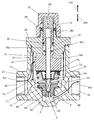
図1は本実施形態における温調トラップの断面図である。弁ケーシング21には流入口26及び流出口29が設けられており、上部にはケーシング蓋22がネジ結合によって取り付けられている。流入口26はトレース伝熱管(図示せず)の末端に接続され、流出口29は排出管(図示せず)に接続される。弁ケーシング21内には弁室53が形成され、この弁室53は流入路27を介して流入口26と連通する。
(Description of the configuration of the temperature control trap)
FIG. 1 is a cross-sectional view of the temperature control trap according to the present embodiment. The
弁ケーシング21内の下方に位置する底室54には、弁座60がネジ結合によって取り付けられ固定されている。弁座60近傍の拡大図が図3及び図4である。弁座60には、弁口62を境に、上流側に弁座上流室61が形成されており、下流側に弁座下流室63が形成されている。開口として形成される弁口62の口径は、弁座上流室61及び弁座下流室63の径よりも小さく構成される。そして、弁室53は、弁室上流室61、弁口62、弁座下流室63、底室54及び流出路28を介して流出口29と連通する。
A
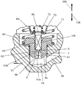
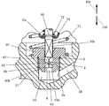
図3及び図4に示すように、弁座下流室63には弁口62に連続する天井面63a、及びこの天井面63aに連続する側壁63bが形成されている。天井面63aは弁口62から側壁63bに向かって傾斜する略円錐形を有しており、側壁63bは円筒形を有している。
As shown in FIGS. 3 and 4, the valve seat
弁室53内には異物を捕捉するための筒状のスクリーン70(図1)が設けられている。流入口26から流入した蒸気やドレンは流入路27を通じ、このスクリーン70を透過して矢印101方向に向けて弁室53内に流入する。
A cylindrical screen 70 (FIG. 1) for capturing foreign matter is provided in the
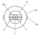
弁室53内には弁軸10が配置されている。この弁軸10を先端側(下流側)から見た図が図2である。弁軸10の先端側には、厚みの薄い直方体形状を有し角部が刃物として構成されている上流刃10bが一体的に形成され、さらにこの上流刃10bの先端には円錐形状を有する弁体2が一体的に形成されている。上流刃10b及び弁体2は弁座上流室61内に位置している。
The
本実施形態においては、弁体2の頂点部には中心棒4が固定されており、この中心棒4は弁口62を貫通して配置されている。なお、中心棒4は弁口62よりも細く形成されているため、弁口62におけるドレンの流れを妨げることはない。そして、中心棒4先端にはさらに下流刃8が一体的に固定されており、この下流刃8は弁座下流室63に位置している。下流刃8は厚みの薄い平面形状を有し、上流刃10bと同様、角部が刃物として構成されている。
In the present embodiment, a
下流刃8は、弁座下流室63の円筒軸方向に沿った断面形状に対応する形状を有している。すなわち、下流刃8は天刃8a及び側刃8bを有しており、下流刃8の天刃8aは傾斜し、この傾斜角度は弁座下流室63の天井面63aの傾斜角度と同様である。また、下流刃8の横幅は弁座下流室63の円筒形の直径に対応している。
The
弁軸10の後端には、調整棒35が配置されている。この調整棒35は、Oリング36を介しケーシング蓋22に対してネジ結合されており、上部に形成された操作用溝35cにドライバー等の工具を嵌め入れて螺入操作が可能になっている。ケーシング蓋22に対する調整棒35の調整位置は、ロックナット89によって固定される。また、調整棒35内には軸方向に沿って調整空間35bが形成されており、この調整空間35b内に弁軸10の後端が挿入されて位置している。なお、ケーシング蓋22から突出した調整棒35の上部は、保護キャップ37によって覆われている。
An adjusting
弁軸10の後端近傍には連結棒10aが固定されている。他方、調整棒35の下部には切割状に形成されたスライド溝35aが設けられており、このスライド溝35aに弁軸10の連結棒10aが挿入されている。すなわち弁軸10は、調整棒35の螺入操作に従って一体的に回転するが、弁軸10はスライド溝35aに沿って矢印105及び矢印106方向に独自に進退することも可能である。
A connecting
調整棒35、弁軸10及び弁座60は同一軸上に配置され、弁軸10の弁体2は弁口62に向けて位置する。弁軸10の中央近傍にはバネ受け10cが固定されている。そして、弁軸10は容器形状の中間部材75の中心穴を貫通しており、この中間部材75はバネ受け10cの下側に当接している。中間部材75は外側が湾曲しており、この湾曲の内側には、弁室53底部との間に復帰用バネ71が取り付けられている。すなわち、弁軸10は、中間部材75及びバネ受け10cを介して常時、復帰用バネ71によって矢印105方向に付勢されている。
The adjusting
弁軸10には、バイメタル積層体40が取り付けられている。バイメタル積層体40の上面は調整棒35の下端面35dに当接し、バイメタル積層体40の下面は平座金73を挟んで中間部材75に当接している。このバイメタル積層体40は、周辺温度に反応して変形する感温部材であるバイメタルを複数、積層して構成されており、周辺温度が高くなった場合に、弁軸10の軸方向に沿って膨張し、周辺温度が低くなった場合に軸方向に沿って収縮する。図1は、バイメタル積層体40が膨張した状態を示している。
A
中間部材75の内側には、弁軸10に取り付けられた弁体付勢バネ72が配置されている。この弁体付勢バネ72の上部は平座金73に当接し、下部はワッシャー85を介してバネ受け10cの上側に当接している。
A valve
(温調トラップの動作の説明)
次に、この温調トラップの動作を説明する。初期段階においては、弁室53内はエアーが充満しており、バイメタル積層体40は収縮している。そして、弁軸10は、バネ受け10cが復帰バネ71の付勢を受け、矢印105方向に移動した状態にある(図示せず)。このとき、弁体2も弁口62から矢印105方向に退去して、弁口62は開弁されている。
(Explanation of operation of temperature control trap)
Next, the operation of the temperature control trap will be described. In the initial stage, the inside of the
配管系統が蒸気移送を開始すると、トレース伝熱管を通して流入口26からドレンが流入する。初期段階のドレンは低温であり、このドレンがエアーを弁口62から押し出し、矢印102方向に向けて流出口29に排気する。続いて、低温のドレンも同様の経路をたどって流出口29から排水される。
When the piping system starts transferring steam, drain flows in from the
この後、弁室53には、高温の蒸気によって熱せられた高温のドレンが流入する。弁室53内のドレンの温度が上昇したことによって、バイメタル積層体40は徐々に膨張する。膨張するバイメタル積層体40は、平座金73、弁体付勢バネ72及びワッシャー85を介して弁棒10のバネ受け10cを矢印106方向に押圧する。このとき、比較的、強力な弁体付勢バネ72は収縮しないため、バイメタル積層体40の膨張はそのまま弁軸10に伝わり、弁体2は弁口62に進入し、弁口62を閉弁する。なお、このとき復帰バネ71は、バイメタル積層体40の膨張に押圧されて圧縮する。
Thereafter, the high-temperature drain heated by the high-temperature steam flows into the
弁口62の閉弁によって、ドレンの排水は停止され、弁室53及びトレース伝熱管には設定された基準温度のドレンが滞留することになる。これによって、トレース伝熱管は重油の輸送管等の加熱対象を加熱する。その後、加熱対象との熱交換によって、トレース伝熱管内のドレンの温度は徐々に低下し、弁室53内のドレンの温度も基準温度を下回ることになる。
By closing the
バイメタル積層体40は、このドレンの温度低下に反応し収縮を開始する。バイメタル積層体40の収縮によって、復帰バネ71は伸張して復帰し、中間部材75を介して弁軸10のバネ受け10cを押し上げ、弁軸10は矢印105方向に移動して、弁体2は弁口62を開弁する。これによって、基準温度を下回ったドレンは弁口62を通じて流出口29に排水される。この後、高温のドレンが弁室53に流入し、バイメタル積層体40の膨張によって再び弁口62は閉弁され、基準温度のドレンが滞留する。
The
以上のように、バイメタル積層体40が弁室53内のドレンの温度に反応して、膨張、収縮することによって、弁軸10の弁体2が昇降し、弁口62は開弁と閉弁を繰り返して、弁室53及びトレース伝熱管内のドレンは設定された基準温度に保たれる。
As described above, the
なお、バイメタル積層体40が膨張し、弁体2が弁口62を完全に閉弁した後もドレンの温度が引き続き上昇し、これに反応してバイメタル積層体40がさらに膨張することがある。この場合、バイメタル積層体40への過度の負担を避けるために、弁体付勢バネ72が復帰バネ71とともに収縮してバイメタル積層体40の膨張を吸収する。
Incidentally, even after the
弁室53及びトレース伝熱管内のドレンの基準温度は、自在に調整して設定することができる。基準温度を調整する場合は、温調トラップの上部の保護キャップ37を取り外し、ロックナット89を緩めた上で操作用溝35cにドライバー等の工具を嵌め入れて螺入操作し、調整棒35を軸方向に移動させる。
The reference temperature of the drain in the
調整棒35を弁室53内に向けて締め込めば、調整棒35の端面35dがバイメタル積層体40を押圧して、弁軸10自体の位置が矢印106方向に下降移動するため、基準温度を低く設定することができる。逆に、調整棒35を緩めれば、復帰バネ71の付勢によって、弁軸10自体の位置が矢印105方向に上昇移動するため、基準温度を高く設定することができる。
If the
(クリーニング動作の説明)
弁室53内の弁口62やその近傍には、温調トラップの作動にともなって錆やスケール等の異物が付着して堆積する。本実施形態では、基準温度を設定するために調整棒35及び弁軸10が移動自在であることを利用し、調整棒35を螺入操作することによって異物を除去してクリーニングを行う。
(Description of cleaning operation)
Foreign substances such as rust and scale adhere to and accumulate on the
弁座上流室61のクリーニングを行う場合、温調トラップの上部の保護キャップ37を取り外し、ロックナット89を緩めた上で操作用溝35cにドライバー等の工具を嵌め入れる。そして、調整棒35を締め込めば、連結棒10aを介して弁軸10が回転しながら矢印106方向に下降し、上流刃10bが回転して弁座上流室61の内面に付着した異物をそぎ落として除去する。
When cleaning the valve seat
図3は、調整棒35を限界まで締め込んだ状態を示している。弁軸10の上流刃10bが弁座上流室61の側壁の異物そぎ落すとともに、弁座上流室61の先端部分の刃が弁座上流室61の底面に当接することによって底面の異物もそぎ落とす。
FIG. 3 shows a state in which the adjusting
この状態から調整棒35を逆に緩めれば、上流刃10bは逆回転しながら矢印105方向に上昇し、残存した異物がそぎ落とされる。そぎ落とされた異物は、弁口62を通じてドレン等と共に流出路28から排出される。
If the adjusting
ところで、異物は弁座上流室61に付着することもあるが、弁口62の下流側に位置する弁座下流室63内に付着することも多い。本実施形態では、弁座下流室63内に付着した異物を、調整棒35の螺入操作によって下流刃8で除去してクリーニングを行う。
Incidentally, the foreign matter may adhere to the valve seat
弁座下流室63内のクリーニングを行う場合、図1に示す温調トラップの上部の保護キャップ37を取り外し、ロックナット89を緩めた上で操作用溝35cにドライバー等の工具を嵌め入れる。そして、調整棒35を緩めれば、連結棒10aを介して弁軸10が回転しながら矢印105方向に上昇し、弁座下流室63の内面に近接して下流刃8が回転する。
When cleaning the inside of the valve seat
図4は、調整棒35を限界まで緩めた状態を示している。下流刃8の天刃8aが弁座下流室63の天井面63aに当接している。この状態に至る過程で、下流刃8の側刃8bが弁座下流室63の側壁63bに付着した異物をそぎ落とし、下流刃8の天刃8aが弁座下流室63の天井面63aに付着した異物をそぎ落とす。
FIG. 4 shows a state in which the adjusting
そして、この状態から調整棒35を逆に締め込めば、下流刃8は逆回転しながら矢印106方向に下降し、残存した異物がそぎ落とされる。そぎ落とされた異物は、ドレン等と共に流出路28から排出される。
Then, when the
異物を除去した後は、図1に示す調整棒35を所定の基準温度に応じた高さに調整して位置決めする。その後、ロックナット89で位置を固定し、保護キャップ37を取り付け、クリーニング処理を終了する。
After removing the foreign matter, the
[その他の実施形態]
前記実施形態においては、下流刃8が弁座下流室63のみをクリーニングする構成を示したが、下流刃8に中心棒4に沿った上方向に延びる突出刃を一体的に形成し、この突出刃が弁座下流室63のクリーニング動作の際、弁口62内に進入して同時に弁口62の内周に付着した異物をそぎ落とすようにしてもよい。
[Other embodiments]
In the above-described embodiment, the configuration in which the
また、前記実施形態においては、本願に係るクリーニング手段を有する温度応動弁を温調トラップに適用した例を掲げたが、温度に反応して開弁、閉弁を行うものであれば他の種類の弁に適用してもよい。 Further, in the above-described embodiment, an example in which the temperature responsive valve having the cleaning means according to the present invention is applied to the temperature control trap is described, but other types that open and close the valve in response to the temperature are used. May be applied to the valve.
さらに、前記実施形態においては、排出室として弁座下流室63を例示したが、弁孔(弁口62等)に連続して形成される内側面を有している限り、他の形状・構造の排出室を採用することもできる。また、削剥部として、弁座下流室63の形状に対応した形状を有する下流刃8を例示したが、排出室の内面に近接して回転するものであれば、他の形状・構造のものを用いることができる。
Further, in the above-described embodiment, the valve seat
また、連動部として、弁口62を貫通して配置された中心棒4を例示したが、これに限定されるものではなく、調整手段(弁軸10等)の回転操作に直接又は間接に連動して削剥部(下流刃8等)を回転させるものであれば、他の構成を採用することもできる。
Also, as the interlocking part, the
2:弁体 4:中心棒 8:下流刃 10:弁軸 21:弁ケーシング
53:弁室 54:底室 61:弁座上流室 62:弁口 63:弁座下流室
63a:天井面 63b:側壁
2: Valve body 4: Center rod 8: Downstream blade 10: Valve shaft 21: Valve casing
53: Valve room 54: Bottom room 61: Valve seat upstream room 62: Valve port 63: Valve seat downstream room
63a:
Claims (2)
本体内に形成され、弁空間と排出空間とを連通させる開口としての弁孔、
弁空間内に位置し、調整弁を有する調整手段であって、回転操作又は流体の温度に応動して、調整弁が当該回転軸方向に沿って弁孔に対し進出又は退去し、弁孔の開口の程度を変化させる調整手段、
を備えたクリーニング手段を有する温度応動弁において、
排出空間に位置する削剥部、及び調整手段の回転操作に連動させて削剥部を排出空間の内面に近接して回転させる連動部、を有するクリーニング手段、
を備えたことを特徴とするクリーニング手段を有する温度応動弁。 A body connected to a piping system for transferring a fluid, the body having a valve space and a discharge space,
A valve hole as an opening formed in the main body and communicating the valve space and the discharge space,
Adjusting means having an adjusting valve located in the valve space, wherein the adjusting valve advances or retreats with respect to the valve hole along the rotation axis direction in response to the rotation operation or the temperature of the fluid, and Adjusting means for changing the degree of the opening,
A temperature responsive valve having cleaning means comprising:
A cleaning unit having a shaving unit located in the discharge space, and an interlocking unit that rotates the shaving unit in proximity to the inner surface of the discharge space in conjunction with the rotation operation of the adjusting unit;
A temperature-responsive valve having cleaning means, comprising:
排出空間に形成された排出室であって、弁孔に連続して形成される上面、及び上面に連続して形成される側面を有する排出室、
を備えており、
前記連動部は弁孔を貫通して位置し、調整手段と削剥部とを接続し、
前記削剥部は、排出室に対応する形状を有しており、前記回転操作に従って排出室の上面及び側面に近接して回転する、
ことを特徴とするクリーニング手段を有する温度応動弁。
A temperature responsive valve having a cleaning means according to claim 1,
A discharge chamber formed in the discharge space, an upper surface formed continuously with the valve hole, and a discharge chamber having side surfaces formed continuously with the upper surface,
With
The interlocking part is located through the valve hole, connects the adjusting means and the exfoliation part,
The shaved portion has a shape corresponding to the discharge chamber, and rotates in proximity to the upper surface and side surfaces of the discharge chamber according to the rotation operation.
A temperature-responsive valve having cleaning means.
Priority Applications (1)
| Application Number | Priority Date | Filing Date | Title |
|---|---|---|---|
| JP2018119632A JP7104572B2 (en) | 2018-06-25 | 2018-06-25 | Temperature-responsive valve with cleaning means |
Applications Claiming Priority (1)
| Application Number | Priority Date | Filing Date | Title |
|---|---|---|---|
| JP2018119632A JP7104572B2 (en) | 2018-06-25 | 2018-06-25 | Temperature-responsive valve with cleaning means |
Publications (2)
| Publication Number | Publication Date |
|---|---|
| JP2020002955A true JP2020002955A (en) | 2020-01-09 |
| JP7104572B2 JP7104572B2 (en) | 2022-07-21 |
Family
ID=69099413
Family Applications (1)
| Application Number | Title | Priority Date | Filing Date |
|---|---|---|---|
| JP2018119632A Active JP7104572B2 (en) | 2018-06-25 | 2018-06-25 | Temperature-responsive valve with cleaning means |
Country Status (1)
| Country | Link |
|---|---|
| JP (1) | JP7104572B2 (en) |
Cited By (2)
| Publication number | Priority date | Publication date | Assignee | Title |
|---|---|---|---|---|
| CN114719927A (en) * | 2022-04-14 | 2022-07-08 | 扬州市检验检测中心 | Intelligent flowmeter |
| JP2023100380A (en) * | 2022-01-06 | 2023-07-19 | 株式会社テイエルブイ | Automatic valve with cleaning means |
Citations (6)
| Publication number | Priority date | Publication date | Assignee | Title |
|---|---|---|---|---|
| JPS4926122U (en) * | 1972-06-05 | 1974-03-06 | ||
| JPH02117479U (en) * | 1989-01-26 | 1990-09-20 | ||
| JPH0532884U (en) * | 1991-10-09 | 1993-04-30 | 株式会社クボタ | Liquid filling device |
| JP2002372166A (en) * | 2001-06-15 | 2002-12-26 | Tlv Co Ltd | Temperature responsive valve |
| JP2005147222A (en) * | 2003-11-13 | 2005-06-09 | Miyawaki Inc | Temperature sensitive valve |
| JP2005201355A (en) * | 2004-01-15 | 2005-07-28 | Tlv Co Ltd | Temperature-responsive valve |
-
2018
- 2018-06-25 JP JP2018119632A patent/JP7104572B2/en active Active
Patent Citations (6)
| Publication number | Priority date | Publication date | Assignee | Title |
|---|---|---|---|---|
| JPS4926122U (en) * | 1972-06-05 | 1974-03-06 | ||
| JPH02117479U (en) * | 1989-01-26 | 1990-09-20 | ||
| JPH0532884U (en) * | 1991-10-09 | 1993-04-30 | 株式会社クボタ | Liquid filling device |
| JP2002372166A (en) * | 2001-06-15 | 2002-12-26 | Tlv Co Ltd | Temperature responsive valve |
| JP2005147222A (en) * | 2003-11-13 | 2005-06-09 | Miyawaki Inc | Temperature sensitive valve |
| JP2005201355A (en) * | 2004-01-15 | 2005-07-28 | Tlv Co Ltd | Temperature-responsive valve |
Cited By (2)
| Publication number | Priority date | Publication date | Assignee | Title |
|---|---|---|---|---|
| JP2023100380A (en) * | 2022-01-06 | 2023-07-19 | 株式会社テイエルブイ | Automatic valve with cleaning means |
| CN114719927A (en) * | 2022-04-14 | 2022-07-08 | 扬州市检验检测中心 | Intelligent flowmeter |
Also Published As
| Publication number | Publication date |
|---|---|
| JP7104572B2 (en) | 2022-07-21 |
Similar Documents
| Publication | Publication Date | Title |
|---|---|---|
| US9551435B2 (en) | Method of preventing clogging in a microvalve | |
| KR20170064222A (en) | Bellows-type Steam Trap | |
| KR100460935B1 (en) | Condensate discharge device | |
| EP1421309B1 (en) | Temperature actuated valve | |
| JP2020002955A (en) | Temperature responsive valve with cleaning means | |
| JPS58191397A (en) | Fluid control valve | |
| JP7212527B2 (en) | steam trap | |
| JP7261031B2 (en) | Temperature responsive valve with cleaning means | |
| JP7663228B2 (en) | Automatic valve with cleaning mechanism | |
| JP7320258B2 (en) | Temperature responsive valve with cleaning means | |
| KR102631300B1 (en) | Apparatus for controlling fluid flow | |
| JP7649036B2 (en) | Automatic valve with cleaning mechanism | |
| JP3983118B2 (en) | Freezing prevention device | |
| JP7763477B2 (en) | Automatic valve with cleaning means | |
| DK1925872T3 (en) | Vandudlader | |
| US6371437B1 (en) | Thermally operated valve for automatically modulating the flow of fluids and methods and tool for making the same | |
| JP2023166178A (en) | Valve device having cleaning mechanism | |
| JP4833091B2 (en) | Thermally responsive steam trap | |
| JP2022120751A (en) | Fitting with drain valve | |
| JP7152194B2 (en) | Fluid trap with cleaning means | |
| JP3636377B2 (en) | Freezing prevention device | |
| JP6308653B2 (en) | Low temperature operation valve | |
| US20140261786A1 (en) | Drain systems | |
| JP7790711B2 (en) | Valve system with anti-locking function | |
| KR20160144810A (en) | Safety valve having functions of preventing frozen of water and draining of hot water |
Legal Events
| Date | Code | Title | Description |
|---|---|---|---|
| A621 | Written request for application examination |
Free format text: JAPANESE INTERMEDIATE CODE: A621 Effective date: 20210520 |
|
| A977 | Report on retrieval |
Free format text: JAPANESE INTERMEDIATE CODE: A971007 Effective date: 20220623 |
|
| TRDD | Decision of grant or rejection written | ||
| A01 | Written decision to grant a patent or to grant a registration (utility model) |
Free format text: JAPANESE INTERMEDIATE CODE: A01 Effective date: 20220705 |
|
| A61 | First payment of annual fees (during grant procedure) |
Free format text: JAPANESE INTERMEDIATE CODE: A61 Effective date: 20220708 |
|
| R150 | Certificate of patent or registration of utility model |
Ref document number: 7104572 Country of ref document: JP Free format text: JAPANESE INTERMEDIATE CODE: R150 |
|
| R250 | Receipt of annual fees |
Free format text: JAPANESE INTERMEDIATE CODE: R250 |