JP2020002966A - Rotary actuator and robot forceps - Google Patents
Rotary actuator and robot forceps Download PDFInfo
- Publication number
- JP2020002966A JP2020002966A JP2018120498A JP2018120498A JP2020002966A JP 2020002966 A JP2020002966 A JP 2020002966A JP 2018120498 A JP2018120498 A JP 2018120498A JP 2018120498 A JP2018120498 A JP 2018120498A JP 2020002966 A JP2020002966 A JP 2020002966A
- Authority
- JP
- Japan
- Prior art keywords
- rotary actuator
- housing
- cover
- rotary
- internal space
- Prior art date
- Legal status (The legal status is an assumption and is not a legal conclusion. Google has not performed a legal analysis and makes no representation as to the accuracy of the status listed.)
- Pending
Links
Images


Classifications
-
- A—HUMAN NECESSITIES
- A61—MEDICAL OR VETERINARY SCIENCE; HYGIENE
- A61B—DIAGNOSIS; SURGERY; IDENTIFICATION
- A61B34/00—Computer-aided surgery; Manipulators or robots specially adapted for use in surgery
- A61B34/70—Manipulators specially adapted for use in surgery
-
- A—HUMAN NECESSITIES
- A61—MEDICAL OR VETERINARY SCIENCE; HYGIENE
- A61B—DIAGNOSIS; SURGERY; IDENTIFICATION
- A61B17/00—Surgical instruments, devices or methods
- A61B17/28—Surgical forceps
- A61B17/2804—Surgical forceps with two or more pivotal connections
-
- A—HUMAN NECESSITIES
- A61—MEDICAL OR VETERINARY SCIENCE; HYGIENE
- A61B—DIAGNOSIS; SURGERY; IDENTIFICATION
- A61B34/00—Computer-aided surgery; Manipulators or robots specially adapted for use in surgery
- A61B34/30—Surgical robots
-
- B—PERFORMING OPERATIONS; TRANSPORTING
- B25—HAND TOOLS; PORTABLE POWER-DRIVEN TOOLS; MANIPULATORS
- B25J—MANIPULATORS; CHAMBERS PROVIDED WITH MANIPULATION DEVICES
- B25J15/00—Gripping heads and other end effectors
- B25J15/02—Gripping heads and other end effectors servo-actuated
- B25J15/0206—Gripping heads and other end effectors servo-actuated comprising articulated grippers
-
- B—PERFORMING OPERATIONS; TRANSPORTING
- B25—HAND TOOLS; PORTABLE POWER-DRIVEN TOOLS; MANIPULATORS
- B25J—MANIPULATORS; CHAMBERS PROVIDED WITH MANIPULATION DEVICES
- B25J17/00—Joints
- B25J17/02—Wrist joints
- B25J17/0241—One-dimensional joints
- B25J17/025—One-dimensional joints mounted in series
-
- F—MECHANICAL ENGINEERING; LIGHTING; HEATING; WEAPONS; BLASTING
- F15—FLUID-PRESSURE ACTUATORS; HYDRAULICS OR PNEUMATICS IN GENERAL
- F15B—SYSTEMS ACTING BY MEANS OF FLUIDS IN GENERAL; FLUID-PRESSURE ACTUATORS, e.g. SERVOMOTORS; DETAILS OF FLUID-PRESSURE SYSTEMS, NOT OTHERWISE PROVIDED FOR
- F15B15/00—Fluid-actuated devices for displacing a member from one position to another; Gearing associated therewith
- F15B15/08—Characterised by the construction of the motor unit
- F15B15/12—Characterised by the construction of the motor unit of the oscillating-vane or curved-cylinder type
-
- F—MECHANICAL ENGINEERING; LIGHTING; HEATING; WEAPONS; BLASTING
- F16—ENGINEERING ELEMENTS AND UNITS; GENERAL MEASURES FOR PRODUCING AND MAINTAINING EFFECTIVE FUNCTIONING OF MACHINES OR INSTALLATIONS; THERMAL INSULATION IN GENERAL
- F16J—PISTONS; CYLINDERS; SEALINGS
- F16J15/00—Sealings
- F16J15/16—Sealings between relatively-moving surfaces
- F16J15/32—Sealings between relatively-moving surfaces with elastic sealings, e.g. O-rings
- F16J15/3204—Sealings between relatively-moving surfaces with elastic sealings, e.g. O-rings with at least one lip
-
- A—HUMAN NECESSITIES
- A61—MEDICAL OR VETERINARY SCIENCE; HYGIENE
- A61B—DIAGNOSIS; SURGERY; IDENTIFICATION
- A61B17/00—Surgical instruments, devices or methods
- A61B2017/00535—Surgical instruments, devices or methods pneumatically or hydraulically operated
- A61B2017/00539—Surgical instruments, devices or methods pneumatically or hydraulically operated hydraulically
-
- A—HUMAN NECESSITIES
- A61—MEDICAL OR VETERINARY SCIENCE; HYGIENE
- A61B—DIAGNOSIS; SURGERY; IDENTIFICATION
- A61B17/00—Surgical instruments, devices or methods
- A61B17/28—Surgical forceps
- A61B17/29—Forceps for use in minimally invasive surgery
- A61B2017/2926—Details of heads or jaws
- A61B2017/2932—Transmission of forces to jaw members
-
- A—HUMAN NECESSITIES
- A61—MEDICAL OR VETERINARY SCIENCE; HYGIENE
- A61B—DIAGNOSIS; SURGERY; IDENTIFICATION
- A61B34/00—Computer-aided surgery; Manipulators or robots specially adapted for use in surgery
- A61B34/30—Surgical robots
- A61B2034/305—Details of wrist mechanisms at distal ends of robotic arms
-
- A—HUMAN NECESSITIES
- A61—MEDICAL OR VETERINARY SCIENCE; HYGIENE
- A61B—DIAGNOSIS; SURGERY; IDENTIFICATION
- A61B34/00—Computer-aided surgery; Manipulators or robots specially adapted for use in surgery
- A61B34/30—Surgical robots
- A61B34/37—Leader-follower robots
Landscapes
- Engineering & Computer Science (AREA)
- Health & Medical Sciences (AREA)
- Surgery (AREA)
- Life Sciences & Earth Sciences (AREA)
- Mechanical Engineering (AREA)
- Robotics (AREA)
- General Engineering & Computer Science (AREA)
- Animal Behavior & Ethology (AREA)
- Nuclear Medicine, Radiotherapy & Molecular Imaging (AREA)
- Molecular Biology (AREA)
- Heart & Thoracic Surgery (AREA)
- General Health & Medical Sciences (AREA)
- Public Health (AREA)
- Veterinary Medicine (AREA)
- Medical Informatics (AREA)
- Biomedical Technology (AREA)
- Fluid Mechanics (AREA)
- Physics & Mathematics (AREA)
- Ophthalmology & Optometry (AREA)
- Actuator (AREA)
- Surgical Instruments (AREA)
Abstract
【課題】ハウジングとカバーとの間に外側シール部材を介在させつつベーンで仕切られた圧力室の一方から他方へ作動流体が逃げることを抑制することができるロータリアクチュエータを提供する。【解決手段】ロータリアクチュエータ3Aは、ベーン6が配置される内部空間41を有するハウジング4と、ハウジングに取り付けられて内部空間を覆うカバー5と、を備え、ハウジングとカバーとの間には、内部空間を取り巻くように断面三角形状で環状のシール溝9が形成されており、このシール溝内に外側シール部材8Bが挿入されている。【選択図】図4PROBLEM TO BE SOLVED: To provide a rotary actuator capable of suppressing escape of a working fluid from one side of a pressure chamber partitioned by a vane to the other while interposing an outer seal member between a housing and a cover. A rotary actuator (3A) includes a housing (4) having an internal space (41) on which vanes (6) are arranged, and a cover (5) attached to the housing and covering the internal space. An annular seal groove 9 having a triangular cross section is formed so as to surround the space, and the outer seal member 8B is inserted into the seal groove. [Selection diagram] Fig. 4
Description
本発明は、ロータリアクチュエータおよびそのロータリアクチュエータを含むロボット鉗子に関する。 The present invention relates to a rotary actuator and a robot forceps including the rotary actuator.
一般的に、作動流体により駆動されるロータリアクチュエータでは、ハウジングの内部空間内にベーンが配置され、そのハウジングの内部空間がカバーにより覆われる。例えば、特許文献1には、ベーンにシール部材が装着され、このシール部材によってベーンの先端面とハウジング(特許文献1では「本体チューブ」と称呼)との間およびベーンの側面とカバーとの間がシールされるように構成されたロータリアクチュエータが開示されている。
Generally, in a rotary actuator driven by a working fluid, a vane is arranged in an internal space of a housing, and the internal space of the housing is covered with a cover. For example, in
ところで、特許文献1に開示されたロータリアクチュエータでは、ハウジングとカバーとの間にはシール部材が介在していない。しかしながら、作動流体がベーン収容空間からハウジングとカバーの間を通って外部へ漏れ出すことを防止するためには、ハウジングとカバーとの間にシール部材(例えば、Oリング)を介在させることが望ましい。
By the way, in the rotary actuator disclosed in
その場合、一般的には、ハウジングとカバーとの間に、ハウジングの内部空間を取り巻くように断面矩形状で環状のシール溝が形成され、このシール溝内に外側シール部材が挿入される。 In that case, generally, an annular seal groove having a rectangular cross section is formed between the housing and the cover so as to surround the internal space of the housing, and the outer seal member is inserted into the seal groove.
しかしながら、断面矩形状のシール溝の場合、シール溝の内側側面と外側シール部材との間に隙間が形成されるため、その隙間を通じて、ベーンで仕切られた圧力室の一方から他方へ作動流体が逃げるおそれがある。 However, in the case of a seal groove having a rectangular cross section, since a gap is formed between the inner side surface of the seal groove and the outer seal member, the working fluid flows from one side of the pressure chamber partitioned by the vane to the other through the gap. There is a risk of escape.
そこで、本発明は、ハウジングとカバーとの間に外側シール部材を介在させつつベーンで仕切られた圧力室の一方から他方へ作動流体が逃げることを抑制することができるロータリアクチュエータを提供することを目的とする。また、本発明は、そのロータリアクチュエータを含むロボット鉗子を提供することも目的とする。 Accordingly, the present invention provides a rotary actuator capable of suppressing the working fluid from escaping from one of the pressure chambers partitioned by vanes to the other while interposing an outer seal member between the housing and the cover. Aim. Another object of the present invention is to provide a robot forceps including the rotary actuator.
前記課題を解決するために、本発明のロータリアクチュエータは、ベーンが配置される内部空間を有するハウジングと、前記ハウジングに取り付けられて前記内部空間を覆うカバーと、を備え、前記ハウジングと前記カバーとの間には、前記内部空間を取り巻くように断面三角形状で環状のシール溝が形成されており、このシール溝内に外側シール部材が挿入されている、ことを特徴とする。 In order to solve the above problem, a rotary actuator according to the present invention includes a housing having an internal space in which a vane is arranged, and a cover attached to the housing to cover the internal space, wherein the housing and the cover An annular seal groove having a triangular cross section is formed between the seal grooves so as to surround the internal space, and an outer seal member is inserted into the seal groove.
上記の構成によれば、シール溝が断面三角形状であるので、断面矩形状のシール溝と比べて、シール溝内の外側シール部材の充填率を大きくすることができる。これにより、ハウジングとカバーとの間に外側シール部材を介在させつつベーンで仕切られた圧力室の一方から他方へ作動流体が逃げることを抑制することができる。 According to the above configuration, since the seal groove has a triangular cross section, the filling rate of the outer seal member in the seal groove can be increased as compared with the seal groove having a rectangular cross section. Thus, it is possible to suppress the working fluid from escaping from one side of the pressure chamber partitioned by the vane to the other while the outer seal member is interposed between the housing and the cover.
前記ハウジングは、前記内部空間の周囲に位置する基準面と、前記基準面の外周縁部から立ち上がる環状の壁面を含み、前記カバーは、前記壁面の内部に嵌まり込む突出部を含み、前記突出部の先端面の外周縁部には、前記基準面と前記壁面との間のコーナー部との間に前記シール溝を形成する傾斜面が形成されていてもよい。この構成によれば、ハウジングにカバーを取り付ける際に、ハウジングの基準面と壁面との間のコーナー部に予め外側シール部材を配置することができる。これにより、ハウジングに対してカバーを容易に取り付けることができる。 The housing includes a reference surface positioned around the inner space, and an annular wall surface rising from an outer peripheral edge of the reference surface, the cover including a protrusion fitted into the wall surface, An inclined surface that forms the seal groove between the reference surface and a corner between the wall surface may be formed on an outer peripheral edge of the distal end surface of the portion. According to this configuration, when the cover is attached to the housing, the outer seal member can be arranged in advance at a corner between the reference surface and the wall surface of the housing. Thereby, the cover can be easily attached to the housing.
例えば、前記突出部には、前記内部空間と共にベーン収容空間を形成する凹部が形成されていてもよい。 For example, a recess may be formed in the protruding portion to form a vane housing space together with the internal space.
前記ベーンは、前記ロータリアクチュエータの回転軸を中心とする円柱部と、前記円柱部から径方向外向きに突出する板部を含み、上記のロータリアクチュエータは、前記ベーンに装着された、前記板部および前記円柱部を取り巻く内側シール部材をさらに備え、前記内側シール部材における前記板部の先端面上に位置する部分には、前記ハウジングの基準面および前記突出部の先端面と対応する位置に切り込みが形成されていてもよい。この構成によれば、ハウジングの壁面の内部にカバーの突出部を嵌め込む際に、ハウジングの基準面と突出部の先端面との間に内側シール部材が噛み込むことを防止することができる。 The vane includes a cylindrical portion centered on a rotation axis of the rotary actuator, and a plate portion protruding radially outward from the cylindrical portion, wherein the rotary actuator is mounted on the vane, And an inner seal member surrounding the cylindrical portion, wherein a portion of the inner seal member located on the distal end surface of the plate portion is cut into a position corresponding to the reference surface of the housing and the distal end surface of the protrusion. May be formed. According to this configuration, when the protrusion of the cover is fitted inside the wall surface of the housing, it is possible to prevent the inner seal member from being caught between the reference surface of the housing and the distal end surface of the protrusion.
前記突出部の先端面は、前記ハウジングの基準面に当接してもよい。この構成によれば、カバーの突出部の周囲に位置する後退面が、ハウジングの壁面の周囲に位置する頂き面に当接する場合に比べて、ベーン収容空間からの漏れ量を低減することができる。なお、ベーン収容空間から外部への漏れ出しは外側シール部材により防止されるため、ここでのベーン収容空間からの漏れ量の低減は、圧力室の一方から他方へ作動流体が逃げることを効果的に抑制できることを意味する。 The tip surface of the protrusion may abut on a reference surface of the housing. According to this configuration, the amount of leakage from the vane housing space can be reduced as compared with the case where the receding surface located around the projecting portion of the cover comes into contact with the top surface located around the wall surface of the housing. . In addition, since leakage from the vane housing space to the outside is prevented by the outer seal member, the reduction of the leak amount from the vane housing space here is effective in that the working fluid escapes from one of the pressure chambers to the other. Means that it can be suppressed.
前記カバーは、前記内部空間に嵌まり込む突出部と、前記突出部の周囲に位置する後退面を含み、前記ハウジングは、前記構体面が当接する頂き面を含み、前記頂き面面の内周縁部には、前記突出部の外周面と前記後退面との間のコーナー部との間に前記シール溝を形成する傾斜面が形成されていてもよい。この構成によれば、ハウジングにカバーを取り付ける際に、カバーの突出部の外周面と後退面との間のコーナー部に予め外側シール部材を配置することができる。これにより、ハウジングに対してカバーを容易に取り付けることができる。 The cover includes a protruding portion that fits into the internal space, and a retreating surface located around the protruding portion, the housing includes a squeezing surface with which the structural surface abuts, and an inner peripheral edge of the squeezing surface. The portion may be formed with an inclined surface that forms the seal groove between an outer peripheral surface of the protruding portion and a corner portion between the receding surface. According to this configuration, when attaching the cover to the housing, the outer seal member can be arranged in advance at the corner between the outer peripheral surface of the projecting portion of the cover and the receding surface. Thereby, the cover can be easily attached to the housing.
例えば、前記シール溝の断面積に対する前記外側シール部材の断面積の割合は、90%以上であってもよい。 For example, a ratio of a sectional area of the outer seal member to a sectional area of the seal groove may be 90% or more.
また、本発明の1つの側面からのロボット鉗子は、挿入管と、前記挿入管の先端に設けられた、互いに対向する一対の爪の一方を揺動させる第1ロータリアクチュエータおよび前記一対の爪の他方を揺動させる第2ロータリアクチュエータを含むグリッパーと、前記挿入管に対して前記グリッパーを揺動させる第3ロータリアクチュエータと、を備え、前記第1ロータリアクチュエータ、前記第2ロータリアクチュエータおよび前記第3ロータリアクチュエータのそれぞれが、上記のロータリアクチュエータであり、前記第1ロータリアクチュエータの回転軸と前記第2ロータリアクチュエータの回転軸が同軸上に位置し、前記第3ロータリアクチュエータの回転軸が前記第1ロータリアクチュエータおよび前記第2ロータリアクチュエータの回転軸と直交する、ことを特徴とする。 In addition, a robot forceps according to one aspect of the present invention includes an insertion tube, a first rotary actuator provided at a distal end of the insertion tube, for swinging one of a pair of claws opposed to each other, and a pair of claw of the pair of claws. A gripper including a second rotary actuator for swinging the other, and a third rotary actuator for swinging the gripper with respect to the insertion tube; the first rotary actuator, the second rotary actuator, and the third rotary actuator; Each of the rotary actuators is the above-mentioned rotary actuator, and the rotation axis of the first rotary actuator and the rotation axis of the second rotary actuator are coaxially located, and the rotation axis of the third rotary actuator is the first rotary actuator. Actuator and second rotary actuator Orthogonal to the rotation axis, characterized in that.
さらに、本発明の別の側面からのロボット鉗子は、挿入管と、前記挿入管の先端に設けられた、互いに対向する一対の爪の一方を揺動させる第1ロータリアクチュエータおよび前記一対の爪の他方を揺動させる第2ロータリアクチュエータを含むグリッパーと、前記挿入管に対して前記グリッパーを揺動させる第3ロータリアクチュエータと、を備え、前記第1ロータリアクチュエータの回転軸と前記第2ロータリアクチュエータの回転軸が同軸上に位置し、前記第3ロータリアクチュエータの回転軸が前記第1ロータリアクチュエータおよび前記第2ロータリアクチュエータの回転軸と直交する、ことを特徴とする。 Furthermore, a robot forceps according to another aspect of the present invention includes an insertion tube, a first rotary actuator provided at the distal end of the insertion tube, which swings one of a pair of claws opposed to each other, and a pair of the claw of the pair of claws. A gripper including a second rotary actuator for swinging the other, and a third rotary actuator for swinging the gripper with respect to the insertion tube; and a rotation axis of the first rotary actuator and a rotation shaft of the second rotary actuator. A rotation axis is located coaxially, and a rotation axis of the third rotary actuator is orthogonal to rotation axes of the first rotary actuator and the second rotary actuator.
これらのロボット鉗子では、第3ロータリアクチュエータの回転軸を中心として、患部を把持する一対の爪の向きを任意に変更することができる。 In these robot forceps, the directions of the pair of claws for gripping the affected part can be arbitrarily changed about the rotation axis of the third rotary actuator.
本発明によれば、ハウジングとカバーとの間に外側シール部材を介在させつつベーンで仕切られた圧力室の一方から他方へ作動流体が逃げることを抑制することができる。 According to the present invention, it is possible to prevent the working fluid from escaping from one of the pressure chambers partitioned by the vane to the other while interposing the outer seal member between the housing and the cover.
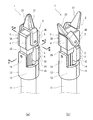
図1(a)および(b)に、本発明の一実施形態に係る第1〜第3ロータリアクチュエータ3A〜3Cが組み込まれたロボット鉗子1の先端部分を示す。
FIGS. 1A and 1B show a distal end portion of a
ロボット鉗子1は、例えば、手術支援システムに用いられる。この場合、スレーブ側装置に取り付けられるロボット鉗子1をマスタ側装置で医師が遠隔操作する。
The
具体的に、ロボット鉗子1は、患者の体内に挿入される挿入管11と、挿入管11の先端に設けられたグリッパー2を含む。挿入管11は、直線状に延びる高剛性の管であってもよいし、フレキシブルな管であってもよい。
Specifically, the
グリッパー2は、互いに対向する一対の爪(第1爪21および第2爪22)と、第1爪21を揺動させる第1ロータリアクチュエータ3Aと、第2爪22を揺動させる第2ロータリアクチュエータ3Bを含む。さらに、ロボット鉗子1は、挿入管11に対してグリッパー2を揺動させる第3ロータリアクチュエータ3Cを含む。
The
第1〜第3ロータリアクチュエータ3A〜3Cのそれぞれは、作動流体により駆動される。本実施形態では、作動流体が、生理食塩水や油などの液体である。図示は省略するが、挿入管11の根本(グリッパー2と反対側)には駆動ユニットが設けられており、この駆動ユニット内に、第1〜第3ロータリアクチュエータ3A〜3Cに対する作動流体の供給および排出を行う給排装置が設けられている。図略の給排装置から第1〜第3ロータリアクチュエータ3A〜3Cへの作動流体の供給および第1〜第3ロータリアクチュエータ3A〜3Cから給排装置への作動流体の排出は、挿入管11内に挿通された複数のチューブ15を通じて行われる。
Each of the first to third
図3に示すように、第1ロータリアクチュエータ3Aの回転軸31と第2ロータリアクチュエータ3Bの回転軸32は同軸上に位置している。また、第3ロータリアクチュエータ3Cの回転軸33は、図2に示すように、第1ロータリアクチュエータ3Aおよび第2ロータリアクチュエータ3Bの回転軸31,32と直交する。このようなロボット鉗子1であれば、第3ロータリアクチュエータ3Cの回転軸33を中心として、患部を把持する第1爪21および第2爪22の向きを任意に変更することができる。
As shown in FIG. 3, the
なお、以下の説明では、説明の便宜上、挿入管11の軸方向のうち先端側を上方、根本側を下方という。
In the following description, for convenience of description, the distal end side in the axial direction of the
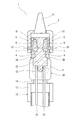
ロボット鉗子1の先端部分の構造に関し、より詳しくは、挿入管11の先端には、保持部材12が固定されている。保持部材12は、2つの半体に分割可能に構成されている。保持部材12は、内部に挿入管11が嵌め込まれる筒状部13と、筒状部13から上向きに突出する、互いに対向する一対の支持片14を含む。そして、この一対の支持片14の間に、グリッパー2のベース25と第3ロータリアクチュエータ3Cが配置されている。
Regarding the structure of the distal end portion of the
図2および図3に示すように、第1〜第3ロータリアクチュエータ3A〜3Cのそれぞれは、ベーン6が配置される内部空間41を有するハウジング4と、ハウジング4に取り付けられて内部空間41を覆うカバー5を含む。本実施形態では、ロータリアクチュエータの軸方向(回転軸が延びる方向)から見たときのハウジング4およびカバー5の形状が略矩形状であるが、ロータリアクチュエータの軸方向から見たときのハウジング4およびカバー5の形状は円形状などの別の形状であってもよい。
As shown in FIGS. 2 and 3, each of the first to third
本実施形態では、第1ロータリアクチュエータ3Aのハウジング4、第2ロータリアクチュエータ3Bのハウジング4、ベース25および第3ロータリアクチュエータ3Cのハウジング4が一体となっており、単一のブロックを構成している。ただし、第1ロータリアクチュエータ3Aのハウジング4、第2ロータリアクチュエータ3Bのハウジング4、ベース25および第3ロータリアクチュエータ3Cのハウジング4の少なくとも1つが別体になっていてもよい。
In the present embodiment, the
また、第1〜第3ロータリアクチュエータ3A〜3Cのそれぞれにおいて、ベーン6にはカバー5を貫通する回転シャフト7が一体的に設けられている。第1ロータリアクチュエータ3Aの回転シャフト7は第1爪21に回転不能に結合されており、第2ロータリアクチュエータ3Bの回転シャフト7は第2爪22に回転不能に結合されている。第3ロータリアクチュエータ3Cの回転シャフト7は一方の支持片14に回転不能に結合されている。つまり、本実施形態では、第3ロータリアクチュエータ3Cのハウジング4およびカバー5が支持片14に対して相対回転する。
In each of the first to third rotary actuators 3 </ b> A to 3 </ b> C, a
ただし、第3ロータリアクチュエータ3Cのハウジング4とカバー5の位置関係が図2とは逆にされ、第3ロータリアクチュエータ3Cのハウジング4が支持片14に固定され、回転シャフト7がベース25に回転不能に結合されてもよい。この場合、ロータリアクチュエータの軸方向から見たときのハウジング4およびカバー5の形状は例えば円形状である。
However, the positional relationship between the
ベース25には、第3ロータリアクチュエータ3Cの回転シャフト7と同軸上に回転シャフト26が設けられている。回転シャフト26は、第3ロータリアクチュエータ3Cの回転シャフト7が結合された支持片14と反対側の支持片14に回転可能に支持されている。
The
上述したチューブ15は、ベース25に接続されている。ベース25および第1〜第3ロータリアクチュエータ3A〜3Cのハウジング4からなるブロックの内部には、各チューブ15から対応する内部空間41に至る複数の流路16(図6参照、図2および図3では作図を省略)が形成されている。
The
第1〜第3ロータリアクチュエータ3A〜3Cは、互いに同じ構造を有している。従って、以下では、図4〜図6を参照し、第1ロータリアクチュエータ3Aの構造を代表して詳細に説明する。
The first to third
本実施形態では、第1ロータリアクチュエータ3Aの軸方向から見たときに、ハウジング4の内部空間41が、ベーン6が180度の角度範囲内で揺動できるように、略半円状の形状を有している。ただし、第1ロータリアクチュエータ3Aの軸方向から見たときのハウジング4の内部空間41の形状は、ベーン6が180度よりも小さな角度範囲内で揺動できるように扇形状であってもよいし、ベーン6が180度よりも大きな角度範囲内で揺動できるように円の一部が欠落した形状(逆扇形状)であってもよい。
In the present embodiment, when viewed from the axial direction of the first
本実施形態では、ハウジング4の内部空間41の深さが、ベーン6の高さの半分程度に設定されている。ただし、内部空間41の深さは、ベーン6の高さよりも小さければ任意に設定可能である。
In the present embodiment, the depth of the
ハウジング4は、内部空間41の周囲に位置する基準面42と、基準面42の外周縁部から立ち上がる環状の壁面43と、壁面43の周囲に位置する頂き面44を含む。本実施形態では、基準面42の外側の輪郭が回転軸31を中心とする円形状である。このため、壁面43は円形筒状である。ただし、基準面42の外側の輪郭は、内部空間41を拡大したような略D字状であってもよい。
The
一方、カバー5は、壁面43の内部に嵌まり込む突出部51と、突出部51の周囲に位置する後退面52を含む。本実施形態では、突出部51の先端面がハウジング4の基準面42に当接する。突出部51の外周面は、ハウジング4の壁面43と僅かの隙間を隔てて対向し、後退面52は、ハウジング4の頂き面44と僅かの隙間を隔てて対向する。
On the other hand, the
突出部51には、ハウジング4の内部空間41と共にベーン収容空間30を形成する凹部53が形成されている。つまり、凹部53の深さと内部空間41の深さの和は、ベーン6の側面間の高さとほぼ等しい。ベーン6は、ベーン収容空間30を第1圧力室3aと第2圧力室3bとに仕切る。
The projecting
上述したように、本実施形態ではカバー5の突出部51の先端面がハウジング4の基準面42に当接するが、突出部51の先端面およびハウジング4の基準面42のうねりや表面粗さなどの影響により、それらの面の間に、ベーン収容空間30からの作動流体の漏れ経路が形成される。
As described above, in the present embodiment, the distal end surface of the projecting
ただし、図7に示すように、カバー5の後退面52がハウジング4の頂き面44に当接し、突出部51の先端面が基準面42と僅かの隙間を隔てて対向してもよい。しかしながら、図5に示す構造であれば、図7に示す構造に比べて、ベーン収容空間30からの漏れ量を低減することができる。
However, as shown in FIG. 7, the receding
ベーン6は、第1ロータリアクチュエータ3Aの回転軸31を中心とする円柱部61と、円柱部61の外周面から径方向外向きに突出する板部62を含む。上述した回転シャフト7は、円柱部61の一方の端面から突出しており、カバー5に回転可能に支持されている。また、円柱部61の他方の端面には、シャフト部63が設けられており、このシャフト部63がハウジング4に回転可能に支持されている。
The
ベーン6には、板部62および円柱部61を取り巻く内側シール部材8Aが装着されている。より詳しくは、板部62の先端面62aには円柱部61の軸方向に延びる直線状の溝64が形成され、板部62のカバー5側の側面およびカバー5と反対側の側面には円柱部61の径方向に延びる直線状の溝65がそれぞれ形成されている。また、円柱部61の両端面には円形状の溝66がそれぞれ形成され、円柱部61には、外周面の板部62と反対側の位置に、当該円柱部61の軸方向に延びる幅広の溝67が形成されている。内側シール部材8Aは、それらの溝64〜67内に挿入されている。
The
内側シール部材8Aにおける板部62の先端面62a上に位置する部分(正確には、溝64に挿入される部分)には、ハウジング4の基準面42および突出部51の先端面と対応する位置に切り込み81が形成されている。切り込み81は、内側シール部材8Aにおける板部62の先端面62a上に位置する部分を板部62の厚さ方向に横断している。図例では、切り込み81の断面形状が三角形状であるが、切り込み81の断面形状は例えば半円状または矩形状であってもよい。
The portion of the
カバー5の突出部51の先端面の外周縁部には、周方向に連続する傾斜面54が形成されている。傾斜面54は、ハウジング4の基準面42と壁面43との間のコーナー部との間に断面三角形状で環状のシール溝9を形成する。つまり、シール溝9は、ハウジング4とカバー5との間に内部空間41を取り巻くように形成されている。
An
シール溝9には、外側シール部材8Bが挿入されている。外側シール部材8Bは、例えば、図5中に二点鎖線で示すように、自然状態では円形状の断面形状を有するOリングである。ただし、外側シール部材8Bの自然状態での断面形状は、楕円状などのその他の形状であってもよい。 An outer seal member 8B is inserted into the seal groove 9. The outer seal member 8B is, for example, an O-ring having a circular cross-sectional shape in a natural state, as shown by a two-dot chain line in FIG. However, the cross-sectional shape of the outer seal member 8B in the natural state may be another shape such as an elliptical shape.
シール溝9の断面積S1に対する外側シール部材S2の断面積の割合(S2/S1)は、90%以上であることが望ましく、95%以上であることがより望ましい。シール溝9の断面積S1は、傾斜面54を基準面42および壁面43まで延長した線と、基準面42および壁面43とで囲まれる区画の面積である。外側シール部材S2の断面積は、自然状態での断面積である。
The ratio of the cross-sectional area of the outer seal member S2 to the cross-sectional area S1 of the seal groove 9 (S2 / S1) is preferably 90% or more, and more preferably 95% or more. The cross-sectional area S1 of the seal groove 9 is an area of a section surrounded by a line obtained by extending the
以上説明したように、本実施形態の第1〜第3ロータリアクチュエータ3A〜3Cでは、シール溝9が断面三角形状であるので、断面矩形状のシール溝と比べて、シール溝9内の外側シール部材8Bの充填率を大きくすることができる。これにより、ハウジング4とカバー5との間に外側シール部材8Bを介在させつつ、ベーン6で仕切られた第1圧力室3aおよび第2圧力室3bの一方から他方へ作動流体が逃げることを抑制することができる。
As described above, in the first to third
さらに、本実施形態では、ハウジング4にカバー5を取り付ける際に、ハウジング4の基準面42と壁面43との間のコーナー部に予め外側シール部材8Bを配置することができる。これにより、ハウジング4に対してカバー5を容易に取り付けることができる。
Furthermore, in the present embodiment, when the
また、本実施形態では、内側シール部材8Aにおける板部62の先端面62a上に位置する部分に切り込み81が形成されているので、ハウジング4の壁面43の内部にカバー5の突出部51を嵌め込む際に、ハウジング4の基準面42と突出部51の先端面との間に内側シール部材8Aが噛み込むことを防止することができる。
Further, in the present embodiment, since the
(変形例)
本発明は上述した実施形態に限定されるものではなく、本発明の要旨を逸脱しない範囲で種々の変形が可能である。
(Modification)
The present invention is not limited to the above-described embodiment, and various modifications can be made without departing from the gist of the present invention.
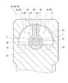
例えば、図8および図9に示すように、ハウジング4の内部空間41の深さがベーン6の高さよりも大きく、カバー5の突出部51が内部空間41に嵌まり込んでもよい。この場合、カバー5の後退面52がハウジング4の頂き面44に当接し、カバー5の突出部51の外周面が、内部空間41の内周面と僅かの隙間を隔てて対向する。
For example, as shown in FIGS. 8 and 9, the depth of the
また、図8および図9に示す構成では、ハウジング4の頂き面44の内周縁部に、周方向に連続する傾斜面45が形成されている。傾斜面45は、カバー5の突出部51の外周面と後退面52との間のコーナー部との間に断面三角形状で環状のシール溝9を形成する。つまり、シール溝9は、ハウジング4とカバー5との間に内部空間41を取り巻くように形成されている。
In the configuration shown in FIGS. 8 and 9, an
図8および図9に示す構成でも、第1実施形態と同様に、断面矩形状のシール溝と比べて、シール溝9内の外側シール部材8Bの充填率を大きくすることができる。これにより、ハウジング4とカバー5との間に外側シール部材8Bを介在させつつ、ベーン6で仕切られた第1圧力室3aおよび第2圧力室3bの一方から他方へ作動流体が逃げることを抑制することができる。
8 and 9, similarly to the first embodiment, the filling rate of the outer seal member 8B in the seal groove 9 can be increased as compared with the seal groove having a rectangular cross section. Thereby, while the outer seal member 8B is interposed between the
さらに、図8および図9に示す構成では、ハウジング4にカバーを取り付ける際に、カバー5の突出部51の外周面と後退面52との間のコーナー部に予め外側シール部材8Bを配置することができる。これにより、ハウジング4に対してカバー5を容易に取り付けることができる。
Further, in the configuration shown in FIGS. 8 and 9, when the cover is attached to the
ところで、断面三角形状のシール溝9は、必ずしもロータリアクチュエータの径方向に平行な面とこれに直交する面との間のコーナー部を利用して形成される必要はない。例えば、断面三角形状のシール溝は、ロータリアクチュエータの径方向に平行な面からV字状に窪む環状の凹部を利用して形成されてもよい。 Incidentally, the seal groove 9 having a triangular cross section does not necessarily need to be formed using a corner portion between a surface parallel to the radial direction of the rotary actuator and a surface orthogonal to the surface. For example, the seal groove having a triangular cross section may be formed using an annular concave portion that is concaved in a V shape from a plane parallel to the radial direction of the rotary actuator.
また、前記実施形態ならびに図8および図9に示す変形例では、ハウジング4の内部空間41が一方向に開口していたが、ハウジング4の内部空間41が両方向に開口しており、ハウジング4の両側にカバー5が配置されてもよい。
Further, in the embodiment and the modified examples shown in FIGS. 8 and 9, the
さらに、図示は省略するが、図8とは逆に、カバー5がハウジング4の内部空間41よりも大きな凹部を有し、ハウジング4がそのカバー5の凹部に嵌まり込むように構成されてもよい。
Although not shown, the
また、本発明のロータリアクチュエータを駆動する作動流体は、必ずしも液体である必要はなく、気体であってもよい。さらに、本発明のロータリアクチュエータは、ロボット鉗子以外の様々な機器に組み込まれてもよい。 Further, the working fluid for driving the rotary actuator of the present invention does not necessarily need to be a liquid, but may be a gas. Further, the rotary actuator of the present invention may be incorporated in various devices other than the robot forceps.
1 ロボット鉗子
11 挿入管
2 グリッパー
21,22 爪
3A 第1ロータリアクチュエータ
3B 第2ロータリアクチュエータ
3C 第3ロータリアクチュエータ
31〜33 回転軸
4 ハウジング
41 内部空間
42 基準面
43 壁面
44 頂き面
5 カバー
51 突出部
52 後退面
53 凹部
54,55 傾斜面
6 ベーン
61 円柱部
62 板部
62a 先端面
8A 内側シール部材
8B 外側シール部材
81 切り込み
9 シール溝
REFERENCE SIGNS
Claims (9)
前記ハウジングに取り付けられて前記内部空間を覆うカバーと、を備え、
前記ハウジングと前記カバーとの間には、前記内部空間を取り巻くように断面三角形状で環状のシール溝が形成されており、このシール溝内に外側シール部材が挿入されている、ロータリアクチュエータ。 A housing having an interior space in which the vanes are located;
A cover attached to the housing to cover the internal space,
A rotary actuator, wherein an annular seal groove having a triangular cross section is formed between the housing and the cover so as to surround the internal space, and an outer seal member is inserted into the seal groove.
前記カバーは、前記壁面の内部に嵌まり込む突出部を含み、
前記突出部の先端面の外周縁部には、前記基準面と前記壁面との間のコーナー部との間に前記シール溝を形成する傾斜面が形成されている、請求項1に記載のロータリアクチュエータ。 The housing includes a reference surface located around the internal space, and an annular wall surface rising from an outer peripheral edge of the reference surface,
The cover includes a protrusion fitted into the inside of the wall surface,
2. The rotary according to claim 1, wherein an inclined surface that forms the seal groove is formed between an outer peripheral edge of a tip end surface of the protrusion and a corner portion between the reference surface and the wall surface. 3. Actuator.
前記ベーンに装着された、前記板部および前記円柱部を取り巻く内側シール部材をさらに備え、
前記内側シール部材における前記板部の先端面上に位置する部分には、前記ハウジングの基準面および前記突出部の先端面と対応する位置に切り込みが形成されている、請求項3に記載のロータリアクチュエータ。 The vane includes a column portion centered on a rotation axis of the rotary actuator, and a plate portion protruding radially outward from the column portion,
Further provided is an inner seal member surrounding the plate portion and the columnar portion, which is mounted on the vane,
The rotary according to claim 3, wherein a cut is formed in a portion of the inner seal member located on a front end surface of the plate portion, at a position corresponding to a reference surface of the housing and a front end surface of the protrusion. Actuator.
前記ハウジングは、前記後退面が当接する頂き面を含み、
前記頂き面の内周縁部には、前記突出部の外周面と前記後退面との間のコーナー部との間に前記シール溝を形成する傾斜面が形成されている、請求項1に記載のロータリアクチュエータ。 The cover includes a protrusion fitted into the internal space, and a receding surface located around the protrusion.
The housing includes a receiving surface with which the retreating surface abuts,
The inclined surface which forms the seal groove between an outer peripheral surface of the protruding portion and a corner portion between the receding surface is formed at an inner peripheral edge portion of the receiving surface, according to claim 1, wherein: Rotary actuator.
前記挿入管の先端に設けられた、互いに対向する一対の爪の一方を揺動させる第1ロータリアクチュエータおよび前記一対の爪の他方を揺動させる第2ロータリアクチュエータを含むグリッパーと、
前記挿入管に対して前記グリッパーを揺動させる第3ロータリアクチュエータと、を備え、
前記第1ロータリアクチュエータ、前記第2ロータリアクチュエータおよび前記第3ロータリアクチュエータのそれぞれが、請求項1〜7の何れか一項に記載のロータリアクチュエータであり、
前記第1ロータリアクチュエータの回転軸と前記第2ロータリアクチュエータの回転軸が同軸上に位置し、
前記第3ロータリアクチュエータの回転軸が前記第1ロータリアクチュエータおよび前記第2ロータリアクチュエータの回転軸と直交する、ロボット鉗子。 An insertion tube,
A gripper provided at the distal end of the insertion tube and including a first rotary actuator for swinging one of a pair of claws opposed to each other and a second rotary actuator for swinging the other of the pair of claws;
A third rotary actuator for swinging the gripper with respect to the insertion tube,
Each of said 1st rotary actuator, said 2nd rotary actuator, and said 3rd rotary actuator is a rotary actuator as described in any one of Claims 1-7,
The rotation axis of the first rotary actuator and the rotation axis of the second rotary actuator are located coaxially,
Robot forceps, wherein a rotation axis of the third rotary actuator is orthogonal to rotation axes of the first rotary actuator and the second rotary actuator.
前記挿入管の先端に設けられた、互いに対向する一対の爪の一方を揺動させる第1ロータリアクチュエータおよび前記一対の爪の他方を揺動させる第2ロータリアクチュエータを含むグリッパーと、
前記挿入管に対して前記グリッパーを揺動させる第3ロータリアクチュエータと、を備え、
前記第1ロータリアクチュエータの回転軸と前記第2ロータリアクチュエータの回転軸が同軸上に位置し、
前記第3ロータリアクチュエータの回転軸が前記第1ロータリアクチュエータおよび前記第2ロータリアクチュエータの回転軸と直交する、ロボット鉗子。 An insertion tube,
A gripper provided at the distal end of the insertion tube and including a first rotary actuator for swinging one of a pair of claws opposed to each other and a second rotary actuator for swinging the other of the pair of claws;
A third rotary actuator for swinging the gripper with respect to the insertion tube,
The rotation axis of the first rotary actuator and the rotation axis of the second rotary actuator are located coaxially,
Robot forceps, wherein a rotation axis of the third rotary actuator is orthogonal to rotation axes of the first rotary actuator and the second rotary actuator.
Priority Applications (4)
| Application Number | Priority Date | Filing Date | Title |
|---|---|---|---|
| JP2018120498A JP2020002966A (en) | 2018-06-26 | 2018-06-26 | Rotary actuator and robot forceps |
| PCT/JP2019/020996 WO2020003853A1 (en) | 2018-06-26 | 2019-05-28 | Rotary actuator and robotic forceps |
| US17/256,479 US20210128259A1 (en) | 2018-06-26 | 2019-05-28 | Rotary actuator and robotic forceps |
| EP19827077.9A EP3816456A4 (en) | 2018-06-26 | 2019-05-28 | ROTARY ACTUATOR AND ROBOTIC FORCEPS |
Applications Claiming Priority (1)
| Application Number | Priority Date | Filing Date | Title |
|---|---|---|---|
| JP2018120498A JP2020002966A (en) | 2018-06-26 | 2018-06-26 | Rotary actuator and robot forceps |
Publications (1)
| Publication Number | Publication Date |
|---|---|
| JP2020002966A true JP2020002966A (en) | 2020-01-09 |
Family
ID=68984845
Family Applications (1)
| Application Number | Title | Priority Date | Filing Date |
|---|---|---|---|
| JP2018120498A Pending JP2020002966A (en) | 2018-06-26 | 2018-06-26 | Rotary actuator and robot forceps |
Country Status (4)
| Country | Link |
|---|---|
| US (1) | US20210128259A1 (en) |
| EP (1) | EP3816456A4 (en) |
| JP (1) | JP2020002966A (en) |
| WO (1) | WO2020003853A1 (en) |
Family Cites Families (17)
| Publication number | Priority date | Publication date | Assignee | Title |
|---|---|---|---|---|
| GB663821A (en) * | 1946-06-19 | 1951-12-27 | United Aircraft Corp | Improvements in or relating to vane motors |
| US3030934A (en) * | 1958-06-17 | 1962-04-24 | Bogue Elec Mfg Co | Hydraulic actuator |
| GB958841A (en) * | 1961-06-23 | 1964-05-27 | Bouge Electric Mfg Co | Improvements in or relating to hydraulically actuated devices |
| JPS524996U (en) * | 1975-06-26 | 1977-01-13 | ||
| JPS55140104U (en) * | 1979-03-26 | 1980-10-06 | ||
| DE3776972D1 (en) * | 1986-06-09 | 1992-04-09 | Allied Signal Inc | HYDRAULIC SWING LEVER ACTUATOR. |
| FR2612572B1 (en) * | 1987-03-18 | 1991-04-12 | Europ Propulsion | FLUIDIC DEVICE WITH ROTARY PALLET WITHOUT INTERNAL SEAL |
| JP4287354B2 (en) * | 2004-10-25 | 2009-07-01 | 株式会社日立製作所 | Surgical instruments |
| US7559450B2 (en) * | 2005-02-18 | 2009-07-14 | Ethicon Endo-Surgery, Inc. | Surgical instrument incorporating a fluid transfer controlled articulation mechanism |
| JP4635043B2 (en) * | 2005-03-29 | 2011-02-16 | 株式会社東芝 | manipulator |
| JP2011185431A (en) | 2010-03-08 | 2011-09-22 | Pubot Giken:Kk | Wide-angle vane type rocking actuator |
| DE102012212510B4 (en) * | 2012-07-17 | 2014-02-13 | Richard Wolf Gmbh | Endoscopic instrument |
| DE102012025101A1 (en) * | 2012-12-20 | 2014-06-26 | avateramedical GmBH | Active positioning device of a surgical instrument and a surgical robotic system comprising it |
| DE102014204568B4 (en) * | 2014-03-12 | 2019-05-23 | Fraunhofer-Gesellschaft zur Förderung der angewandten Forschung e.V. | Surgical instrument |
| CN106572889B (en) * | 2014-08-13 | 2019-09-06 | 柯惠Lp公司 | Robot-controlled gripping with mechanical advantages |
| DE102014217796B4 (en) * | 2014-09-05 | 2025-07-17 | Richard Wolf Gmbh | Instrument, in particular medical-endoscopic instrument or technoscope |
| JP6646570B2 (en) * | 2016-12-28 | 2020-02-14 | 川崎重工業株式会社 | Robot forceps |
-
2018
- 2018-06-26 JP JP2018120498A patent/JP2020002966A/en active Pending
-
2019
- 2019-05-28 WO PCT/JP2019/020996 patent/WO2020003853A1/en not_active Ceased
- 2019-05-28 EP EP19827077.9A patent/EP3816456A4/en not_active Withdrawn
- 2019-05-28 US US17/256,479 patent/US20210128259A1/en not_active Abandoned
Also Published As
| Publication number | Publication date |
|---|---|
| WO2020003853A1 (en) | 2020-01-02 |
| EP3816456A1 (en) | 2021-05-05 |
| EP3816456A4 (en) | 2022-03-09 |
| US20210128259A1 (en) | 2021-05-06 |
Similar Documents
| Publication | Publication Date | Title |
|---|---|---|
| JP6932738B2 (en) | Endoscope sheath | |
| ES2864884T3 (en) | Needleless connector with flexible valve | |
| US9399301B2 (en) | Joint seal structure of robot | |
| JP2009028156A5 (en) | ||
| JP5360387B2 (en) | Rotor drive mechanism and pump device including the same | |
| BR112012001634B1 (en) | folding valve, needle-free access device and method for making needle-free access device | |
| ES2662795T3 (en) | Rotating piston pump | |
| JP2013027940A (en) | Suction-type robot hand with weight measurement function | |
| CN102840263A (en) | Rotary damper | |
| JP5909949B2 (en) | Inscribed gear pump | |
| JP6380436B2 (en) | Robot arm | |
| JP2019527111A5 (en) | ||
| JP2020002966A (en) | Rotary actuator and robot forceps | |
| BRPI0805749A2 (en) | trocar seal improvement | |
| CN109996503A (en) | Robot pliers | |
| JP2005308097A (en) | Open / close valve and method for opening / closing vacuum chamber opening | |
| JP2009291234A (en) | Dental mixing apparatus | |
| JP3210186U (en) | 2-port valve | |
| JP2007077805A (en) | Pump rotor device | |
| JP6469525B2 (en) | Electric pump | |
| JP2021076212A (en) | Control valve | |
| JP2008151113A (en) | Vane pump | |
| JP4824597B2 (en) | Joint mechanism | |
| JP2010540847A (en) | Rotatable fittings | |
| CN109737225B (en) | Check valve and range hood |