JP2020002996A - Disc brake device - Google Patents
Disc brake device Download PDFInfo
- Publication number
- JP2020002996A JP2020002996A JP2018122403A JP2018122403A JP2020002996A JP 2020002996 A JP2020002996 A JP 2020002996A JP 2018122403 A JP2018122403 A JP 2018122403A JP 2018122403 A JP2018122403 A JP 2018122403A JP 2020002996 A JP2020002996 A JP 2020002996A
- Authority
- JP
- Japan
- Prior art keywords
- cam
- lever
- brake device
- rotation center
- brake
- Prior art date
- Legal status (The legal status is an assumption and is not a legal conclusion. Google has not performed a legal analysis and makes no representation as to the accuracy of the status listed.)
- Pending
Links
Images







Landscapes
- Braking Arrangements (AREA)
Abstract
【課題】動力発生源を小型化することができるディスクブレーキ装置を提供する。【解決手段】ディスクブレーキ装置100は、ブレーキ本体11に回動可能に支持され、他端部25のパッドアッセンブリ33でブレーキロータ35を挟圧する一対のブレーキアーム13と、ロッド47を進退動させるエアチャンバ43と、一端55が一端部23に連結されたカムホルダ57に対してそれぞれ回動可能に連結され、他端59がロッド47に連結されたレバーピン53に対してそれぞれ回動可能に連結される一対のカムレバー15と、カムホルダ57に回転自在に保持されて一端55に設けられた回動中心軸61を介して回動可能に連結されたカムレバー15の回動によって伝達される力を倍力してブレーキアーム13を回動させる偏心カム17と、回動中心軸61を一対の一端部23の拡開方向に沿う直線X上にそれぞれ案内するレバー保持部材19と、を備える。【選択図】図2PROBLEM TO BE SOLVED: To provide a disc brake device capable of downsizing a power generation source. A disc brake device (100) is rotatably supported by a brake body (11), and a pair of brake arms (13) that pinch a brake rotor (35) by a pad assembly (33) of the other end (25) and air that moves a rod (47) forward and backward. The chamber 43 is rotatably connected to the cam holder 57 having one end 55 connected to the one end 23, and the other end 59 is rotatably connected to the lever pin 53 connected to the rod 47. The force transmitted by the rotation of the pair of cam levers 15 and the rotation of the cam levers 15 rotatably held by the cam holder 57 and rotatably connected via the rotation center shaft 61 provided at the one end 55 is boosted. The eccentric cam 17 for rotating the brake arm 13 and the rotation center shaft 61 on the straight line X along the expansion direction of the pair of one ends 23 respectively. It comprises a lever holding member 19, the. [Selection diagram] Figure 2
Description
本発明は、ディスクブレーキ装置に関する。 The present invention relates to a disc brake device.
主に鉄道車両等で用いられるディスクブレーキ装置は、空圧(特許文献1、2等)や、サーボモータの回転(特許文献3等)を動力発生源とした梃子式のものが一般的である。この種のディスクブレーキ装置では、キャリパを小型化するためにウェッジ等の倍力機構を併用しているものが多い。
2. Description of the Related Art Disc brake devices mainly used in railway vehicles and the like are generally of a lever type using pneumatic pressure (
しかしながら、ウェッジ等の倍力機構を用いても、必要軸力の確保から動力発生源(アクチュエータ)が比較的大型化していた。 However, even if a boosting mechanism such as a wedge is used, the power generation source (actuator) has been relatively large due to the required axial force.
本発明は上記状況に鑑みてなされたもので、その目的は、倍力機構をコンパクトにして動力発生源を小型化することができるディスクブレーキ装置を提供することにある。 The present invention has been made in view of the above circumstances, and an object of the present invention is to provide a disk brake device capable of reducing the power generation source by making the booster mechanism compact.
本発明に係る上記目的は、下記構成により達成される。
(1) 車体に支持されるブレーキ本体と、前記ブレーキ本体に対して一端部と他端部との間の支持部が回動可能に支持され、前記他端部にそれぞれ取り付けられたパッドアッセンブリがブレーキロータを両側から挟圧する一対のブレーキアームと、前記ブレーキ本体に取り付けられ、出力部材を進退動させるアクチュエータと、一端が前記一端部に連結されたカムホルダに対してそれぞれ回動可能に連結されると共に、他端が前記出力部材に連結された入力部材に対してそれぞれ回動可能に連結される一対のカムレバーと、前記カムホルダにそれぞれ回転自在に保持され、前記一端に設けられた回動中心軸を介して回動可能に連結された前記カムレバーの回動によって伝達される力を倍力して前記支持部を回動支点に前記ブレーキアームを回動させる偏心カムと、前記回動中心軸を一対の前記一端部の拡開方向に沿う直線上にそれぞれ案内するレバー保持部材と、を備えることを特徴とするディスクブレーキ装置。
The above object according to the present invention is achieved by the following configurations.
(1) A brake body supported by a vehicle body and a support portion between one end and the other end are rotatably supported by the brake body, and a pad assembly attached to the other end is provided. A pair of brake arms for clamping the brake rotor from both sides, an actuator attached to the brake body for moving the output member forward and backward, and one end rotatably connected to a cam holder connected to the one end. A pair of cam levers each of which has the other end rotatably connected to an input member connected to the output member; and a rotation center shaft provided at the one end and rotatably held by the cam holder. The force transmitted by the rotation of the cam lever rotatably connected via the shaft is boosted to rotate the brake arm about the support portion as a rotation fulcrum. A disc brake device comprising: an eccentric cam to be moved; and a lever holding member that guides the rotation center axis on a straight line along a direction in which the pair of the one end portions expands.
上記(1)の構成のディスクブレーキ装置によれば、一端部と他端部との間の支持部が、ブレーキ本体に対してそれぞれ回動可能に支持される一対のブレーキアームの一端部には、一対のカムホルダがそれぞれ連結されている。一対のブレーキアームは、それぞれのカムホルダが離間すれば、一端部が拡開し、支持部を回動中心に回動した他端部のパッドアッセンブリがブレーキロータを挟圧する。
各カムホルダには、一対のカムレバーのそれぞれの一端(外端)が回動可能に連結される。この一対のカムレバーのそれぞれの他端(内端)は、レバーピン等の入力部材により回動自在に連結される。入力部材には、出力部材が連結されている。出力部材は、入力部材を軸線直交方向に押圧可能とする。
さらに、それぞれのカムホルダには、偏心カムが回動自在に保持されている。一対のカムレバーのそれぞれの一端には、回動中心軸が設けられる。カムレバーは、この回動中心軸が偏心カムに軸支されることで、カムホルダのそれぞれに回動可能に連結されている。一対の偏心カムに軸支されたそれぞれの回動中心軸は、レバー保持部材によりブレーキアームの一端部の拡開方向に沿う直線上に案内される。
一対のカムレバーは、入力部材が軸線直交方向に押圧されると、それぞれの回動中心軸が拡開方向に沿う直線上で離反方向に移動する。一対の回動中心軸は、それぞれの偏心カムを介して一対のカムホルダを離反方向に移動させる(第1増幅機構)。偏心カムは、自身のカムの回転中心線に対して回動中心軸を偏芯して軸支している。偏心カムは、この偏芯によりカムレバーの一端における変位を、カムホルダを離反方向へ移動させる送り量に反映させることができる(第2増幅機構)。従って、偏心カムは、この離反方向の変位を反映させた送り量により、カムレバーに伝達された力を倍力してカムホルダを介しブレーキアームの一端部を拡開できる。
このように、本構成のディスクブレーキ装置では、カムレバーと、ブレーキアームの一端部とを連結するカムホルダに、偏心カムを組み込んで保持している。カムレバーは、偏心カムを介してカムホルダに連結されているので、倍力機構をコンパクトに構成できる。また、本構成のディスクブレーキ装置は、偏心カムにおけるカムの回転中心線に対する回動中心軸の偏芯量を変えることで、倍力の調整を容易に行うことも可能となる。更に、本構成のディスクブレーキ装置は、一対のカムレバーと偏心カムによって大きな倍力比を設定することが可能になり、最大出力の小さいアクチュエータを使用することができる。
According to the disk brake device having the configuration of the above (1), the support portion between the one end and the other end is provided at one end of a pair of brake arms rotatably supported by the brake body. , A pair of cam holders are respectively connected. One end of the pair of brake arms is expanded when the respective cam holders are separated from each other, and the pad assembly at the other end pivoted about the supporting portion presses the brake rotor.
One end (outer end) of each of a pair of cam levers is rotatably connected to each cam holder. The other ends (inner ends) of the pair of cam levers are rotatably connected by input members such as lever pins. An output member is connected to the input member. The output member allows the input member to be pressed in a direction orthogonal to the axis.
Further, an eccentric cam is rotatably held in each cam holder. A rotation center shaft is provided at one end of each of the pair of cam levers. The cam lever is rotatably connected to each of the cam holders by the pivot center shaft being supported by the eccentric cam. Each rotation center axis supported by the pair of eccentric cams is guided by a lever holding member on a straight line along the expanding direction of one end of the brake arm.
When the input member is pressed in the direction orthogonal to the axis, the pair of cam levers move in a direction away from each other on a straight line along the expanding direction. The pair of rotation center axes move the pair of cam holders in the separating direction via the respective eccentric cams (first amplification mechanism). The eccentric cam eccentrically supports the rotation center axis with respect to the rotation center line of the cam itself. The eccentric cam can reflect the displacement at one end of the cam lever due to the eccentricity to the feed amount for moving the cam holder in the separating direction (second amplification mechanism). Therefore, the eccentric cam can expand one end of the brake arm via the cam holder by boosting the force transmitted to the cam lever by the feed amount reflecting the displacement in the separating direction.
As described above, in the disc brake device of the present configuration, the eccentric cam is incorporated and held in the cam holder that connects the cam lever and one end of the brake arm. Since the cam lever is connected to the cam holder via the eccentric cam, the booster mechanism can be made compact. Further, in the disc brake device of this configuration, the adjustment of the boost can be easily performed by changing the amount of eccentricity of the rotation center axis of the eccentric cam with respect to the rotation center line of the cam. Further, in the disk brake device of this configuration, a large boost ratio can be set by the pair of cam levers and the eccentric cam, and an actuator having a small maximum output can be used.
(2) 上記(1)に記載のディスクブレーキ装置であって、前記偏心カムは、前記カムホルダに対するカムの回転中心線からオフセットされた位置で前記回動中心軸に回動可能に連結され、前記カムレバーの回動によって前記回動中心軸を中心として前記カムの回転中心線を円弧状に回動させる、ことを特徴とするディスクブレーキ装置。 (2) The disc brake device according to (1), wherein the eccentric cam is rotatably connected to the rotation center axis at a position offset from a rotation center line of the cam with respect to the cam holder. A disc brake device, wherein a rotation center line of the cam is rotated in an arc around the rotation center axis by rotation of a cam lever.
上記(2)の構成のディスクブレーキ装置によれば、偏心カムが、カムの回転中心線回りで回動自在となってカムホルダに保持される。偏心カムには、カムの回転中心線と平行な回動中心軸を介してカムレバーの一端が回動自在に連結される。回動中心軸は、偏心カムにおけるカムの回転中心線に対してオフセットされた位置(偏心した位置)に配置されている。また、偏心カムは、カムレバーに対しては相対回転が規制されて固定されている。そして、回動中心軸は、上記のように、レバー保持部材によりブレーキアームの一端部の拡開方向に沿う直線上で案内される。
一対のカムレバーは、他端の入力部材が出力部材に押圧されると、それぞれの一端に連結された一対の回動中心軸が拡開方向に沿う直線上で離反する方向に移動する。この際、偏心カムは、カムレバーとの相対回転が規制されているので、回動中心軸の直線上の移動に加え、カムの回転中心線が回動中心軸を中心とした円弧状の軌跡を描いて変位する。即ち、偏心カムは、この変位が、カムホルダを離反方向へ移動させる送り量に反映される。
According to the disc brake device having the configuration (2), the eccentric cam is rotatable around the rotation center line of the cam and is held by the cam holder. One end of a cam lever is rotatably connected to the eccentric cam via a rotation center axis parallel to the rotation center line of the cam. The rotation center axis is disposed at a position (eccentric position) offset from the rotation center line of the eccentric cam. Further, the eccentric cam is fixed with its relative rotation restricted with respect to the cam lever. And, as described above, the rotation center axis is guided by the lever holding member on a straight line along the expanding direction of one end of the brake arm.
When the input member at the other end is pressed by the output member, the pair of cam levers move in a direction in which the pair of rotation center axes connected to the respective one ends are separated on a straight line along the expanding direction. At this time, since the relative rotation of the eccentric cam with respect to the cam lever is regulated, in addition to the linear movement of the rotation center axis, the rotation center line of the cam forms an arc-shaped locus about the rotation center axis. Draw and displace. That is, for the eccentric cam, this displacement is reflected in the feed amount for moving the cam holder in the separating direction.
(3) 上記(2)に記載のディスクブレーキ装置であって、前記カムの回転中心線を中心軸とする円柱状に形成された前記偏心カムが、前記カムホルダに形成された円柱状のカム保持穴に回転自在に保持される、ことを特徴とするディスクブレーキ装置。 (3) The disc brake device according to (2), wherein the eccentric cam formed in a cylindrical shape having a rotation axis of the cam as a central axis is a cylindrical cam holding formed in the cam holder. A disc brake device rotatably held in a hole.
上記(3)の構成のディスクブレーキ装置によれば、偏心カムがカムの回転中心線を回転中心とする円柱状に形成される。円柱状の偏心カムは、カムホルダに形成された同じく円柱状のカム保持穴に、同軸で回動自在に保持される。偏心カムは、カムレバーの一端に相対回転が規制されて固定されているので、入力部材が押圧されてカムレバーが揺動することで、カムホルダのカム保持穴内で回動される。このディスクブレーキ装置によれば、カムホルダに偏心カムを収容し、この偏心カムに回動中心軸を介してカムレバーを連結するので、カムレバーとカムホルダとの連結部分に、コンパクトに構成した倍力機構を組み込むことができる。 According to the disk brake device having the above configuration (3), the eccentric cam is formed in a cylindrical shape having the rotation center line of the cam as the center of rotation. The cylindrical eccentric cam is rotatably held coaxially in a cylindrical cam holding hole formed in the cam holder. Since the eccentric cam is fixed to one end of the cam lever with its relative rotation regulated, the eccentric cam is rotated in the cam holding hole of the cam holder when the input member is pressed and the cam lever swings. According to this disc brake device, since the eccentric cam is housed in the cam holder and the cam lever is connected to the eccentric cam via the rotation center shaft, a compact boosting mechanism is provided at the connecting portion between the cam lever and the cam holder. Can be incorporated.
(4) 上記(2)〜(3)の何れか1つに記載のディスクブレーキ装置であって、前記回動中心軸が、ベアリングを介して前記レバー保持部材に形成されたガイド溝に案内される、ことを特徴とするディスクブレーキ装置。 (4) The disc brake device according to any one of (2) to (3), wherein the rotation center axis is guided by a guide groove formed in the lever holding member via a bearing. A disc brake device.
上記(4)の構成のディスクブレーキ装置によれば、拡開方向に沿う直線上で離反方向に移動するそれぞれの回動中心軸が、ベアリングを介して低摩擦でレバー保持部材のガイド溝に案内される。これにより、入力部材に入力された力は、拡開方向に沿う直線上においてブレーキアームの拡開力としてカムホルダから出力されるまでの伝達損失が低減される。 According to the disk brake device having the above configuration (4), each of the pivot shafts moving in the separating direction on the straight line along the expanding direction is guided to the guide groove of the lever holding member through the bearing with low friction. Is done. Thereby, the transmission loss until the force input to the input member is output from the cam holder as the expanding force of the brake arm on a straight line along the expanding direction is reduced.
(5) 上記(2)〜(4)の何れか1つに記載のディスクブレーキ装置であって、前記カムレバーは、前記回動中心軸を介して回動可能に連結された前記偏心カムを前記カムの回転中心線方向から挟む一対のレバー部材により構成される、ことを特徴とするディスクブレーキ装置。 (5) The disc brake device according to any one of (2) to (4), wherein the cam lever is configured to connect the eccentric cam rotatably connected via the rotation center axis to the eccentric cam. A disc brake device comprising a pair of lever members sandwiched from a rotation center line direction of a cam.
上記(5)の構成のディスクブレーキ装置によれば、一対のカムレバーのそれぞれが、一対のレバー部材からなる。カムレバーは、一対のレバー部材が偏心カムをカムの回転中心線方向から挟む構成とすることにより、一枚の場合に比べ許容応力が大きくなる。また、カムレバーが一枚の場合に生じやすくなるカムレバーに垂直な回動中心軸の倒れ変形を抑制できる。 According to the disk brake device having the configuration (5), each of the pair of cam levers includes a pair of lever members. The cam lever has a configuration in which the pair of lever members sandwich the eccentric cam from the direction of the rotation center line of the cam, so that the allowable stress is larger than that of a single cam lever. In addition, it is possible to suppress the falling deformation of the rotation center axis perpendicular to the cam lever, which is likely to occur when only one cam lever is used.
(6) 上記(2)〜(5)の何れか1つに記載のディスクブレーキ装置であって、前記カムホルダには、前記パッドアッセンブリのライニングの摩耗量に応じて前記カムの回転中心線に対する前記一端部の連結位置を伸長させるアジャスタ機構が設けられる、ことを特徴とするディスクブレーキ装置。 (6) The disc brake device according to any one of (2) to (5), wherein the cam holder is provided with the cam holder with respect to a rotation center line of the cam in accordance with a wear amount of a lining of the pad assembly. A disc brake device provided with an adjuster mechanism for extending a connection position of one end.
上記(6)の構成のディスクブレーキ装置によれば、カムホルダが、アジャスタ機構を介してブレーキアームの一端部に連結される。アジャスタ機構は、ライニングの摩耗量に応じて、カムの回転中心線に対するブレーキアームの一端部の連結位置を伸長させた自動調整を可能とする。 According to the disc brake device having the above configuration (6), the cam holder is connected to one end of the brake arm via the adjuster mechanism. The adjuster mechanism enables automatic adjustment by extending the connection position of one end of the brake arm with respect to the rotation center line of the cam according to the amount of wear of the lining.
(7) 上記(1)〜(6)の何れか1つに記載のディスクブレーキ装置であって、前記車体に取り付けられた取付部材に支持される前記ブレーキ本体が、前記一対のブレーキアームの回動軸の間に挟まれてこれらに直交する方向に延びる前記取付部材の吊り下げ軸に回転自在に保持され、前記ブレーキ本体と前記取付部材との間に設けられて前記ブレーキ本体の揺動を抑制する方向に付勢するばね部材が、前記アクチュエータと共に前記ブレーキ本体に固定されている、ことを特徴とするディスクブレーキ装置。 (7) The disc brake device according to any one of (1) to (6), wherein the brake body supported by an attachment member attached to the vehicle body is configured to rotate the pair of brake arms. The mounting member is rotatably held by a suspension shaft of the mounting member that is sandwiched between dynamic shafts and extends in a direction orthogonal to these, and is provided between the brake body and the mounting member to swing the brake body. A disc brake device, wherein a spring member that urges in a suppressing direction is fixed to the brake body together with the actuator.
上記(7)の構成のディスクブレーキ装置によれば、ブレーキ本体は、車体側に固定される吊り下げ軸回りに揺動(ローリング)自在に保持される。車体側に固定される取付部材と、取付部材に固定された吊り下げ軸に対して揺動自在となったブレーキ本体との間には、ばね部材がアクチュエータと共にブレーキ本体に固定されて設けられる。ばね部材は、ブレーキ本体の揺動を抑制する方向に、ブレーキ本体を付勢する。 According to the disc brake device having the configuration (7), the brake main body is held so as to freely swing (roll) around a suspension shaft fixed to the vehicle body side. A spring member is fixed to the brake body together with the actuator between the mounting member fixed to the vehicle body and the brake body that is swingable with respect to the suspension shaft fixed to the mounting member. The spring member biases the brake body in a direction to suppress the swing of the brake body.
本発明に係るディスクブレーキ装置によれば、倍力機構をコンパクトにして動力発生源を小型化することができる。 ADVANTAGE OF THE INVENTION According to the disc brake device which concerns on this invention, a power-generation source can be miniaturized by making a boost mechanism compact.
以上、本発明について明確に開示した。更に、以下の発明を実施するための形態(以下、「実施形態」という。)の記載から本発明はより明確且つ十分に読み取れるであろう。 The present invention has been specifically disclosed. Further, the present invention will be more clearly and sufficiently read from the following description of embodiments for carrying out the invention (hereinafter, referred to as "embodiments").
以下、本発明に係る実施形態を図面を参照して説明する。
[第1実施形態]
図1は本発明の第1実施形態に係るディスクブレーキ装置100の全体構造を示す斜視図である。
本第1実施形態に係るディスクブレーキ装置100は、例えば鉄道車両用ディスクブレーキに好適に用いることができる。
Hereinafter, embodiments according to the present invention will be described with reference to the drawings.
[First Embodiment]
FIG. 1 is a perspective view showing the entire structure of a
The
ディスクブレーキ装置100は、ブレーキ本体11と、ブレーキアーム13と、カムレバー15と、偏心カム17と、レバー保持部材19と、を主要な部材として有する。
ブレーキ本体11は、車体に固定される取付部材21により支持される。
The
The
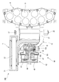
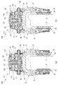
図2は図1に示したディスクブレーキ装置100の水平断面図である。
一対のブレーキアーム13は、ブレーキ本体11に対して一端部23と他端部25との間の支持部27が、回動軸29により回動可能に支持される。一対のブレーキアーム13は、それぞれの他端部25に、複数のライニング31を備えたパッドアッセンブリ33が取り付けられる。一対のブレーキアーム13は、一端部23が離反する方向に拡開されることにより、一対のパッドアッセンブリ33で車輪の両面に配置されたブレーキロータ35を両側から挟圧する。
FIG. 2 is a horizontal sectional view of the
In the pair of
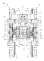
図3は図1に示したディスクブレーキ装置100の側断面図である。
ディスクブレーキ装置100では、ブレーキ本体11が、吊り下げ軸37に回転自在に保持される。これにより、ブレーキ本体11は、車体に取り付けられた取付部材21に、吊り下げ軸37を介して支持される。吊り下げ軸37は、一対のブレーキアーム13の回動軸29の間に挟まれて、これらに直交し且つ車輪軌道に沿う方向に延びる。
FIG. 3 is a side sectional view of the
In the
ブレーキ本体11と取付部材21との間には、図1に示すばね部材39が設けられている。ばね部材39は、揺動を抑制する方向にブレーキ本体11を付勢する。
A
ブレーキ本体11には、動力発生源であるパワーユニット41が固定される。パワーユニット41は、アクチュエータとしてのエアチャンバ43と、レバー機構ユニット45と、からなる。エアチャンバ43は、吊り下げ軸37と同方向の出力部材であるロッド47を備える。エアチャンバ43に内蔵されたエアピストン46後端側のエア室48に、圧縮空気が供給されると、リターンスプリング49に抗してロッド47を軸線に沿う方向に進出させる。即ち、エアチャンバ43は、ブレーキ本体11に取り付けられ、ロッド47を進退可能として作動する。
A
レバー機構ユニット45は、エアチャンバ43と一体に固定され、エアチャンバ43からのロッド47がパッドアッセンブリ33に接近離反する方向へ進退自在に挿入される。レバー機構ユニット45は、レバー機構51を収容する。レバー機構ユニット45は、ロッド47が進出することにより、図2に示すレバー機構51の入力部材であるレバーピン53が押圧されるように構成されている。
The
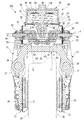
図4は図3に示した吊り下げ軸37に直交する方向の縦断面図である。
レバー機構51は、一対のカムレバー15を有する。カムレバー15は、図2に示す一端55が、ブレーキアーム13の一端部23に連結されたカムホルダ57に対してそれぞれ回動可能に連結される。一対のカムレバー15は、図2に示すように、ロッド47に連結されたレバーピン53に対してそれぞれの他端59が回動可能に連結される。
FIG. 4 is a longitudinal sectional view in a direction perpendicular to the
The
図2に示すように、カムホルダ57には、偏心カム17がそれぞれ回転自在に保持される。偏心カム17は、カムレバー15の一端55に設けられた回動中心軸61を介してカムレバー15と回動可能に連結される。偏心カム17は、カムレバー15の回動によって伝達される力を倍力して、支持部27を回動支点にブレーキアーム13を回動させる。
As shown in FIG. 2, the
レバー機構ユニット45には、図2及び図4に示すレバー保持部材19が設けられる。レバー保持部材19は、回動中心軸61を、一対のブレーキアーム13における一端部23の拡開方向に沿う直線X上にそれぞれ案内する。
The
図2に示すように、偏心カム17は、カムホルダ57に対するカムの回転中心線63からオフセットされた位置で回動中心軸61に回動可能に連結される。偏心カム17は、カムレバー15の回動によって、回動中心軸61を中心として、カムの回転中心線63を円弧状の軌跡を描いて回動(移動)させる。
As shown in FIG. 2, the
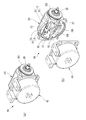
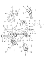
図5は図2に示したレバー機構51の分解斜視図である。
偏心カム17は、カムの回転中心線63を中心軸とする円柱状に形成される。偏心カム17は、カムホルダ57に形成された円柱状のカム保持穴65に回転自在に保持される。偏心カム17とカム保持穴65との間には、円筒状の軸受ブッシュ67が挿入される。軸受ブッシュ67は、偏心カム17とカム保持穴65との摩擦を低減する。
FIG. 5 is an exploded perspective view of the
The
回動中心軸61は、ベアリング69を介してレバー保持部材19に形成されたガイド溝71に案内される。ベアリング69は、内輪が回動中心軸61に固定される。ベアリング69は、この内輪に対し複数の転動体を介して外輪が回転自在に設けられている。ベアリング69は、外輪の外周がガイド溝71に案内される。
The
偏心カム17は、カムの回転中心線63を挟んで回動中心軸61の反対側をロックピン73が貫通している。更に、偏心カム17を貫通したロックピン73は、カムレバー15を貫通する。つまり、カムレバー15と偏心カム17とは、回動中心軸61とロックピン73の2本が貫通することにより、相対回転不能に連結されている。
In the
カムレバー15は、回動中心軸61を介して連結された偏心カム17をカムの回転中心線63方向から挟む一対のレバー部材75により構成される。従って、カムレバー15は、偏心カム17を挟んで二対となった合計4枚のレバー部材75により構成されている。レバー部材75のそれぞれの一端55は、ベアリング69を通して貫通した回動中心軸61の先端にワッシャ77、ナット79が締結されて偏心カム17に固定される。この偏心カム17は、それぞれのカムホルダ57のカム保持穴65で回動自在となる。
The
カムホルダ57には、アジャスタ機構81が設けられる。アジャスタ機構81は、カムの回転中心線63に対するブレーキアーム13の一端部23の連結位置を、回転により伸長可能とする出力軸となるリンクロッド85を有する。リンクロッド85は、調整用歯車87を備える。調整用歯車87の歯には、アジャスタスプリング89に付勢されるアジャスタレバー91が噛み合う。アジャスタレバー91は、ライニング31の摩耗量が一定以上になると、調整用歯車87を一山分回転させた位置でリンクロッド85を送り出した後、調整用歯車87に噛み合って調整用歯車87を回転規制する。
An
次に、上記したディスクブレーキ装置100の作用を説明する。
本第1実施形態に係るディスクブレーキ装置100では、一対のブレーキアーム13の一端部23と他端部25との間の支持部27が、ブレーキ本体11に対してそれぞれ回動可能に支持される。ブレーキアーム13は、それぞれの他端部25に、ブレーキロータ35を両側から挟圧するパッドアッセンブリ33が取り付けられている。また、ブレーキ本体11には、ロッド47を進退動させるエアチャンバ43が取り付けられている。一対のブレーキアーム13の一端部23には、一対のカムホルダ57がそれぞれ連結されている。一対のブレーキアーム13は、それぞれのカムホルダ57が離間すれば、一端部23が拡開し、支持部27を回動中心に回動した他端部25のパッドアッセンブリ33が車輪の両面に配置されたブレーキロータ35を挟圧する。
Next, the operation of the
In the
各カムホルダ57には、一対のカムレバー15のそれぞれの一端55(外端)が回動可能に連結される。この一対のカムレバー15のそれぞれの他端59(内端)は、レバーピン53により回動自在に連結される。このレバーピン53には、ロッド47が連結されている。ロッド47は、レバーピン53を軸線直交方向に押圧可能とする。
One end 55 (outer end) of each of the pair of cam levers 15 is rotatably connected to each
さらに、それぞれのカムホルダ57には、偏心カム17が回動自在に保持されている。一対のカムレバー15のそれぞれの一端55には、回動中心軸61が設けられる。カムレバー15は、この回動中心軸61が偏心カム17に軸支されることで、カムホルダ57のそれぞれに回動可能に連結されている。一対の偏心カム17に軸支されたそれぞれの回動中心軸61は、レバー保持部材19によりブレーキアーム13の一端部23の拡開方向に沿う直線X上に案内される。
Furthermore, the
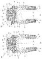
図6は図2に示したレバー機構51の作用図である。
一対のカムレバー15は、レバーピン53が軸線直交方向に押圧されると、それぞれの回動中心軸61が拡開方向に沿う直線X上で離反方向に移動する。一対の回動中心軸61は、それぞれの偏心カム17を介して一対のカムホルダ57を離反方向に移動させる(第1増幅機構)。偏心カム17は、自身のカムの回転中心線63に対して回動中心軸61を偏芯して軸支している。偏心カム17は、この偏芯によりカムレバー15の一端55における変位δを、カムホルダ57を離反方向へ移動させる送り量Δに反映させることができる(第2増幅機構)。送り量Δは、レバー回転中心93からの移動量となる。従って、偏心カム17は、この離反方向の変位δを反映させた送り量Δにより、カムレバー15に伝達された力を倍力してカムホルダ57を介しブレーキアーム13の一端部23を拡開できる。
FIG. 6 is an operation diagram of the
When the
このように、本第1実施形態に係るディスクブレーキ装置100では、カムレバー15と、ブレーキアーム13の一端部23とを連結するカムホルダ57に、偏心カム17を組み込んで保持している。カムレバー15は、偏心カム17を介してカムホルダ57に連結されているので、倍力機構をコンパクトに構成できる。また、本第1実施形態のディスクブレーキ装置100は、偏心カム17におけるカムの回転中心線63に対する回動中心軸61の偏芯量を変えることで、倍力の調整を容易に行うことも可能となる。更に、本第1実施形態のディスクブレーキ装置100は、一対のカムレバー15と偏心カム17によって大きな倍力比を設定することが可能になり、最大出力の小さいエアチャンバ43を使用することができる。
As described above, in the
また、本第1実施形態に係るディスクブレーキ装置100では、偏心カム17が、カムの回転中心線63回りで回動自在となってカムホルダ57に保持される。偏心カム17には、カムの回転中心線63と平行な回動中心軸61を介してカムレバー15の一端55が回動自在に連結される。回動中心軸61は、偏心カム17におけるカムの回転中心線63に対してオフセットされた位置(偏心した位置)に配置されている。また、偏心カム17は、カムレバー15に対しては相対回転が規制されて固定されている。そして、回動中心軸61は、上記のように、レバー保持部材19によりブレーキアーム13の一端部23の拡開方向に沿う直線X上で案内される。
Further, in the
一対のカムレバー15は、他端59のレバーピン53がロッド47に押圧されると、それぞれの一端55に連結された一対の回動中心軸61が拡開方向に沿う直線X上で離反する方向に移動する。この際、偏心カム17は、カムレバー15との相対回転が規制されているので、回動中心軸61の直線X上の移動に加え、カムの回転中心線63が回動中心軸61を中心とした円弧状の軌跡を描いて変位する。即ち、偏心カム17は、この変位δが、カムホルダ57を離反方向へ移動させる送り量Δに反映される。
When the
また、本第1実施形態に係るディスクブレーキ装置100では、偏心カム17がカムの回転中心線63を回転中心とする円柱状に形成される。円柱状の偏心カム17は、カムホルダ57に形成された同じく円柱状のカム保持穴65に、同軸で回動自在に保持される。偏心カム17は、カムレバー15の一端55に相対回転が規制されて固定されているので、レバーピン53が押圧されてカムレバー15が揺動することで、カムホルダ57のカム保持穴内で回動される。このディスクブレーキ装置100によれば、カムホルダ57に偏心カム17を収容し、この偏心カム17に回動中心軸61を介してカムレバー15を連結するので、カムレバー15とカムホルダ57との連結部分に、コンパクトに構成した倍力機構を組み込むことができる。
Further, in the
また、本第1実施形態に係るディスクブレーキ装置100では、回動中心軸61の端に、ベアリング69が同軸で取り付けられる。回動しながらガイド溝71に沿って拡開方向に沿う直線X上で離反方向に移動するそれぞれの回動中心軸61は、ベアリング69の内輪と外輪とが相対回転することで、低摩擦でガイド溝71に案内される。これにより、レバーピン53に入力された力は、拡開方向に沿う直線X上においてブレーキアーム13の拡開力としてカムホルダ57から出力されるまでの伝達損失が低減される。
In the
そして、本第1実施形態に係るディスクブレーキ装置100では、一対のカムレバー15のそれぞれが、一対のレバー部材75からなる。つまり、4枚のレバー部材75が使用される。カムレバー15は、一対のレバー部材75が偏心カム17をカムの回転中心線63方向から挟む構成とすることにより、一枚の場合に比べ許容応力が大きくなる。また、カムレバー15が一枚の場合に生じやすくなるカムレバー15に垂直な回動中心軸61の倒れ変形を抑制できる。
In the
更に、本第1実施形態に係るディスクブレーキ装置100では、カムホルダ57が、アジャスタ機構81を介してブレーキアーム13の一端部23に連結される。アジャスタ機構81は、カムの回転中心線63に対するブレーキアーム13の一端部23の連結位置を、回転により伸長可能とする調整用歯車87を備える。調整用歯車87の歯には、アジャスタスプリング89に付勢されるアジャスタレバー91が噛み合う。アジャスタレバー91は、ライニング31の摩耗量が一定以上になると、調整用歯車87を一山分回転させた位置で送り出し、調整用歯車87に噛み合って調整用歯車87を回転規制する。これにより、アジャスタ機構81は、ライニング31の摩耗量に応じて、カムの回転中心線63に対するブレーキアーム13の一端部23の連結位置を伸長させた自動調整を可能にすることができる。
Further, in the
また、本第1実施形態に係るディスクブレーキ装置100では、車体に取付部材21が固定される。この取付部材21には、吊り下げ軸37が固定される。吊り下げ軸37は、一対のブレーキアーム13の回動軸29の間に挟まれてこれらに直交し且つ車輪軌道に沿う方向に延びる。吊り下げ軸37は、軸回りにブレーキ本体11を回転自在に保持する。ブレーキ本体11は、車体側に固定される吊り下げ軸回りに揺動(ローリング)自在に保持される。車体側に固定される取付部材21と、取付部材21に固定された吊り下げ軸37に対して揺動自在となったブレーキ本体11との間には、ばね部材39がアクチュエータであるエアチャンバ43と共にブレーキ本体11に固定されて設けられる。ばね部材39は、ブレーキ本体11の揺動を抑制する方向に、ブレーキ本体11を付勢する。これにより、ブレーキ本体11は、揺動復帰後に、両側のパッドアッセンブリ33におけるライニング31が、ブレーキロータ35に対して均等なクリアランスで配置されるように構成されている。また、パワーユニット41をブレーキ本体11に固定することにより、球面ベアリング等を不使用として部品点数を削減できる。
In the
[第2実施形態]
次に、本発明の第2実施形態に係るディスクブレーキ装置200を説明する。
図7は本発明の第2実施形態に係るディスクブレーキ装置200の水平断面である。なお、本第2実施形態において上記第1実施形態と同等の部材・部位には同一の符号を付して説明する。
ディスクブレーキ装置200は、ブレーキ本体11と、ブレーキアーム13と、アクチュエータとしてのエアチャンバ43と、駆動方向変換機構としてのレバー機構95と、追従機構97と、を主要な部材として有する。
ブレーキ本体11は、車体に固定される取付部材21により支持される。
[Second embodiment]
Next, a
FIG. 7 is a horizontal cross section of a
The
The
一対のブレーキアーム13は、ブレーキ本体11に対して一端部23と他端部25との間の支持部27が、回動軸29により回動可能に支持される。一対のブレーキアーム13は、それぞれの他端部25に、複数のライニング31を備えたパッドアッセンブリ33が取り付けられる。一対のブレーキアーム13は、一端部23が離反する方向に拡開されることにより、一対のパッドアッセンブリ33で車輪の両面に配置されたブレーキロータ35を両側から挟圧する。
In the pair of
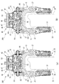
図8は図7に示したディスクブレーキ装置200の側断面図である。
ディスクブレーキ装置200では、ブレーキ本体11が、吊り下げ軸37に回転自在に保持される。これにより、ブレーキ本体11は、車体に取り付けられた取付部材21に、吊り下げ軸37を介して支持される。吊り下げ軸37は、一対のブレーキアーム13の回動軸29の間に挟まれて、これらに直交し且つ車輪軌道に沿う方向に延びる。
FIG. 8 is a side sectional view of the
In the
ブレーキ本体11と取付部材21との間には、ばね部材39が設けられている(図1参照)。ばね部材39は、揺動を抑制する方向にブレーキ本体11を付勢する。
A
ブレーキ本体11には、動力発生源であるパワーユニット99が固定される。パワーユニット99は、アクチュエータとしてのエアチャンバ43と、レバー機構ユニット101と、からなる。エアチャンバ43は、吊り下げ軸37と同方向の出力部材であるロッド47を備える。エアチャンバ43に内蔵されたエアピストン46後端側のエア室48に、圧縮空気が供給されると、リターンスプリング49に抗してロッド47を軸線に沿う方向に進出させる。即ち、エアチャンバ43は、ブレーキ本体11に取り付けられ、ロッド47を進退可能として作動する。
A
レバー機構ユニット101は、エアチャンバ43と一体に固定され、エアチャンバ43からのロッド47がパッドアッセンブリ33に接近離反する方向へ進退自在に挿入される。レバー機構ユニット101は、レバー機構95を収容する。レバー機構ユニット101は、ロッド47が進出することにより、図7に示すレバー機構95の入力部材であるレバーピン53が押圧されるように構成されている。
The
図9は図8に示した吊り下げ軸37に直交する方向の縦断面図である。
レバー機構95は、一対のカムレバー15を有する。カムレバー15は、図7に示す一端55が、ブレーキアーム13の一端部23に連結されたカムホルダ57に対してそれぞれ回動可能に連結される。一対のカムレバー15は、図7に示すように、ロッド47が挿入される後述の揺動ジョイント部材105に連結されたレバーピン53に対してそれぞれの他端59が回動可能に連結される。
FIG. 9 is a longitudinal sectional view in a direction orthogonal to the
The
図7に示すように、カムホルダ57には、偏心カム17がそれぞれ回転自在に保持される。偏心カム17は、カムレバー15の一端55に設けられた回動中心軸61を介してカムレバー15と回動可能に連結される。偏心カム17は、カムレバー15の回動によって伝達される力を倍力して、支持部27を回動支点にブレーキアーム13を回動させる。
As shown in FIG. 7, the
レバー機構ユニット101には、図9に示すレバー保持部材19が設けられる。レバー保持部材19は、回動中心軸61を、一対のブレーキアーム13における一端部23の拡開方向に沿う直線X上にそれぞれ案内する。
The
図7に示すように、偏心カム17は、カムホルダ57に対するカムの回転中心線63からオフセットされた位置で回動中心軸61に回動可能に連結される。偏心カム17は、カムレバー15の回動によって、回動中心軸61を中心として、カムの回転中心線63を円弧状の軌跡を描いて回動(移動)させる。
As shown in FIG. 7, the
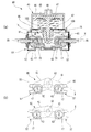
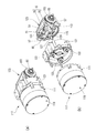
図10の(a)は図7に示したパワーユニット99の斜視図、図10の(b)は(a)に示したパワーユニット99の分解斜視図である。
パワーユニット99は、レバー機構ユニット101の両側からカバー部材103を貫通してリンクロッド85が突出する。リンクロッド85は、ブレーキアーム13の一端部23を拡開方向に押圧する。レバー機構ユニット101には、レバー機構95が収容される。レバー機構95は、駆動方向変換機構を構成する。
FIG. 10A is a perspective view of the
In the
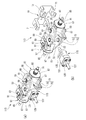
図11の(a)は図17に示したレバー機構95の斜視図、図11の(b)は(a)に示したレバー機構95の分解斜視図である。
レバー機構95は、ロッド47の進退動方向の移動力を、一対のブレーキアーム13の一端部23を拡開揺動する拡開方向の駆動力に変換する。
FIG. 11A is a perspective view of the
The
ロッド47とレバー機構95のレバーピン53との間には、追従機構97が設けられる。追従機構97は、ロッド47に対するレバー機構95の位置変動に対応して、レバーピン53をロッド47に追従させるよう動作する。
A follow-
図12は図11に示したレバー機構95を更に分解した要部斜視図である。
偏心カム17は、カムの回転中心線63(図7参照)を中心軸とする円柱状に形成される。偏心カム17は、カムホルダ57に形成された円柱状のカム保持穴65に回転自在に保持される。偏心カム17とカム保持穴65との間には、円筒状の軸受ブッシュ67が挿入される。軸受ブッシュ67は、偏心カム17とカム保持穴65との摩擦を低減する。
FIG. 12 is a perspective view of a main part of the
The
回動中心軸61は、ベアリング69を介してレバー保持部材19に形成されたガイド溝71(図11参照)に案内される。ベアリング69は、内輪が回動中心軸61に固定される。ベアリング69は、この内輪に対し複数の転動体を介して外輪が回転自在に設けられている。ベアリング69は、外輪の外周がガイド溝71に案内される。
The
偏心カム17は、カムの回転中心線63を挟んで回動中心軸61の反対側をロックピン73が貫通している。更に、偏心カム17を貫通したロックピン73は、カムレバー15を貫通する。つまり、カムレバー15と偏心カム17とは、回動中心軸61とロックピン73の2本が貫通することにより、相対回転不能に連結されている。
In the
カムレバー15は、回動中心軸61を介して連結された偏心カム17をカムの回転中心線63方向から挟む一対のレバー部材75により構成される。従って、カムレバー15は、偏心カム17を挟んで二対となった合計4枚のレバー部材75により構成されている。レバー部材75のそれぞれの一端55は、ベアリング69を通して貫通した回動中心軸61の先端にワッシャ77、ナット79が締結されて偏心カム17に固定される。この偏心カム17は、それぞれのカムホルダ57のカム保持穴65で回動自在となる。
The
カムホルダ57には、アジャスタ機構81が設けられる。アジャスタ機構81は、カムの回転中心線63に対するブレーキアーム13の一端部23の連結部材83を介した連結位置を、回転により伸長可能とする出力軸となるリンクロッド85を有する。リンクロッド85は、調整用歯車87を備える。調整用歯車87の歯には、アジャスタスプリング89に付勢されるアジャスタレバー91が噛み合う。アジャスタレバー91は、ライニング31の摩耗量が一定以上になると、調整用歯車87を一山分回転させた位置でリンクロッド85を送り出した後、調整用歯車87に噛み合って調整用歯車87を回転規制する。
An
図11に示すように、追従機構97は、揺動ジョイント部材105により構成される。揺動ジョイント部材105は、それぞれのレバーピン53を回動自在に支持する一対の嵌合穴107を有する。揺動ジョイント部材105は、嵌合穴107の形成された面に直交する側面に、ピボット軸受穴109を有する。ピボット軸受穴109は、深さ方向に小内径となる略円錐形状に形成される。ピボット軸受穴109は、ブレーキアーム13の拡開方向と直交する方向に進退動するロッド47の先端部をピボット支持する。
As shown in FIG. 11, the follow-
図13の(a)は図10に示したパワーユニット99の水平断面図、図13の(b)は(a)に示したレバー機構95の概略構成図である。
パワーユニット99は、エアチャンバ43に内蔵されたエアピストン46後端側のエア室48に圧縮空気が供給されると、ロッド47をレバー機構ユニット101へ進出させる。レバー機構ユニット101に進出したロッド47は、レバー機構95の揺動ジョイント部材105を押圧する。レバー機構95は、揺動ジョイント部材105が押圧されると、嵌合穴107に嵌合したレバーピン53を押圧する。レバー機構95は、レバーピン53が押圧されることにより、カムレバー15により偏心カム17を介してカムホルダ57を拡開方向へ移動する。
FIG. 13A is a horizontal sectional view of the
When the compressed air is supplied to the
次に、上記したディスクブレーキ装置200の作用を説明する。
本第2実施形態に係るディスクブレーキ装置200では、車体に、ブレーキ本体11が支持される。ブレーキ本体11には、エアチャンバ43が固定される。エアチャンバ43は、ロッド47を進退させる。ブレーキ本体11には、一対のブレーキアーム13が回動可能に支持される。ブレーキアーム13は、一端部23と他端部25との間の支持部27が、ブレーキ本体11に回動軸29を介して支持されて回動自在となる。レバー機構95は、ロッド47の進出方向の移動力を、一対のブレーキアーム13の一端部23を拡開する方向に変換する。一端部同士が拡開された一対のブレーキアーム13は、他端部25にそれぞれ取り付けられたパッドアッセンブリ33が車輪の両面に配置されたブレーキロータ35を両側から挟圧する。
Next, the operation of the
In the
出力部材であるロッド47とレバー機構95との間には、ブレーキロータ35の傾きや、ばね上ばね下の位相差により位置変動が生じる場合がある。この位置変動により、ロッド47と、レバー機構95のレバーピン53とはずれる。追従機構97は、このずれを吸収し、位置変動が生じた場合であってもロッド47とレバーピン53とを力の伝達可能な接続状態に維持する。
A position change may occur between the
本第2実施形態に係るディスクブレーキ装置200のレバー機構95による倍力動作は、上記第1実施形態に係るディスクブレーキ装置100と同一であるので説明は省略する。
本第2実施形態に係るディスクブレーキ装置200では、揺動ジョイント部材105に、レバー機構95の入力部材を回動自在に支持する嵌合穴107が形成される。また、揺動ジョイント部材105には、ブレーキアーム13の拡開方向と直交する方向に進退動するロッド47の先端部をピボット支持するピボット軸受穴109が形成される。追従機構97は、ロッド47が進出すると、揺動ジョイント部材105のピボット軸受穴109が押圧される。押圧された揺動ジョイント部材105は、嵌合穴107に挿入されているレバー機構95のレバーピン53を同方向に押圧する。
The boosting operation by the
In the
図14の(a)は図7に示したディスクブレーキ装置200の開放時の動作説明図、図14の(b)は図7に示したディスクブレーキ装置200の通常制動時の動作説明図である。
この際、ブレーキロータ35の傾きにより生じたロッド47とレバーピン53との位置変動は、揺動ジョイント部材105の嵌合穴107でロッド47が回動することにより吸収される。
FIG. 14A is an explanatory diagram of the operation when the
At this time, the positional change between the
図15の(a)は図14に示したディスクブレーキ装置200のブレーキロータ傾き時の動作説明図、図15の(b)は図14に示したディスクブレーキ装置200の上下位相発生時の動作説明図である。
また、ばね上ばね下の位相差により生じたロッド47とレバーピン53との位置変動は、図15の(b)に示すレバー機構95の矢印方向の移動によって生じる。この位置変動は、ロッド47の先端部に対して揺動ジョイント部材105がピボット運動することにより吸収される。
FIG. 15A is a diagram illustrating the operation of the
In addition, the positional change between the
[第3実施形態]
次に、本発明の第3実施形態に係るディスクブレーキ装置300を説明する。
図16は本発明の第3実施形態に係るディスクブレーキ装置300の全体構造を示す斜視図である。なお、本第3実施形態において上記第1実施形態と同等の部材・部位には同一の符号を付して説明する。
ディスクブレーキ装置300は、ブレーキ本体11と、ブレーキアーム13と、アクチュエータとしてのモータギアユニット111と、駆動方向変換機構としてのレバー機構113と、追従機構115と、を主要な部材として有する。
ブレーキ本体11は、車体に固定される取付部材21により支持される。
[Third embodiment]
Next, a
FIG. 16 is a perspective view showing the entire structure of the
The
The
図17は図16に示したディスクブレーキ装置300の水平断面図である。
一対のブレーキアーム13は、ブレーキ本体11に対して一端部23と他端部25との間の支持部27が、回動軸29により回動可能に支持される。一対のブレーキアーム13は、それぞれの他端部25に、複数のライニング31を備えたパッドアッセンブリ33が取り付けられる。一対のブレーキアーム13は、一端部23が離反する方向に拡開されることにより、一対のパッドアッセンブリ33で車輪の両面に配置されたブレーキロータ35を両側から挟圧する。
FIG. 17 is a horizontal sectional view of the
In the pair of
図18は図17に示したディスクブレーキ装置300の側断面図である。
ディスクブレーキ装置300では、ブレーキ本体11が、吊り下げ軸37に回転自在に保持される。これにより、ブレーキ本体11は、車体に取り付けられた取付部材21に、吊り下げ軸37を介して支持される。吊り下げ軸37は、一対のブレーキアーム13の回動軸29の間に挟まれて、これらに直交し且つ車輪軌道に沿う方向に延びる。
FIG. 18 is a side sectional view of the
In the
ブレーキ本体11と取付部材21との間には、ばね部材39が設けられている(図1参照)。ばね部材39は、揺動を抑制する方向にブレーキ本体11を付勢する。
A
ブレーキ本体11には、動力発生源であるパワーユニット117が固定される。パワーユニット117は、電磁保持ブレーキ119と、アクチュエータとしてのモータギアユニット111と、ばねユニット121と、レバー機構ユニット123と、からなる。
A
電磁保持ブレーキ119には、電磁保持用のソレノイド125が備えられる。電磁保持ブレーキ119は、ソレノイド125への通電により、ボールねじ127に軸力を加え、レバー機構113を直接駆動可能としている。
The
モータギアユニット111は、ばねユニット121を貫通してレバー機構ユニット123に達するボールねじ127を備える。ボールねじ127には、出力部材であるボールナット129が螺合される。ボールナット129は、モータギアユニット111の駆動によりボールねじ127が回転されると、拡開方向と直交する方向に進退動する。
The
ボールナット129には、直動ジョイント部材131が固定される。直動ジョイント部材131は、ボールナット129と共にレバー機構ユニット123の内方で進退する。レバー機構ユニット123は、レバー機構113を収容する。レバー機構ユニット123は、ボールナット129及び直動ジョイント部材131が進出することにより、レバー機構113の入力部材であるレバーピン53が押圧されるように構成されている。
The linear
ばねユニット121は、ボールねじ127を中心に円周方向に複数(本実施例では3つ)のコイルばね133を等間隔に備える。ばねユニット121は、電磁保持ブレーキ119を作動させた際の復帰用の付勢力を蓄勢する。
The
図19は図17に示した吊り下げ軸37に直交する方向の縦断面図である。
レバー機構113は、一対のカムレバー15を有する。カムレバー15は、図17に示す一端55が、ブレーキアーム13の一端部23に連結されたカムホルダ57に対してそれぞれ回動可能に連結される。一対のカムレバー15は、図17に示すように、ボールねじ127と一体固定される直動ジョイント部材131に連結されたレバーピン53に対してそれぞれの他端59が回動可能に連結される。
FIG. 19 is a longitudinal sectional view in a direction orthogonal to the
The
図17に示すように、カムホルダ57には、偏心カム17がそれぞれ回転自在に保持される。偏心カム17は、カムレバー15の一端55に設けられた回動中心軸61を介してカムレバー15と回動可能に連結される。偏心カム17は、カムレバー15の回動によって伝達される力を倍力して、支持部27を回動支点にブレーキアーム13を回動させる。
As shown in FIG. 17, the
レバー機構ユニット123には、図19に示すレバー保持部材19が設けられる。レバー保持部材19は、回動中心軸61を、一対のブレーキアーム13における一端部23の拡開方向に沿う直線X上にそれぞれ案内する。
The
図17に示すように、偏心カム17は、カムホルダ57に対するカムの回転中心線63からオフセットされた位置で回動中心軸61に回動可能に連結される。偏心カム17は、カムレバー15の回動によって、回動中心軸61を中心として、カムの回転中心線63を円弧状の軌跡を描いて回動(移動)させる。
As shown in FIG. 17, the
図20の(a)は図17に示したパワーユニット117の斜視図、図20の(b)は(a)に示したパワーユニット117の分解斜視図である。
パワーユニット117は、レバー機構ユニット123の両側からカバー部材103を貫通してリンクロッド85が突出する。リンクロッド85は、ブレーキアーム13の一端部23を拡開方向に押圧する。レバー機構ユニット123には、レバー機構113が収容される。レバー機構113は、駆動方向変換機構を構成する。
20A is a perspective view of the
The
図21の(a)は図17に示したレバー機構113の斜視図、図21の(b)は(a)に示したレバー機構113の分解斜視図である。
レバー機構113は、ボールナット129の進退動方向の移動力を、一対のブレーキアーム13の一端部23を拡開揺動する拡開方向の駆動力に変換する。
21A is a perspective view of the
The
ボールナット129とレバー機構113のレバーピン53との間には、追従機構115が設けられる。追従機構115は、ボールナット129に固定された直動ジョイント部材131により構成される。直動ジョイント部材131は、レバーピン53を拡開方向へ移動自在に支持するスライド溝135を有して拡開方向と直交する方向に進退動する。
A follow-up
図22は図21に示したレバー機構113を更に分解した要部斜視図である。
一対のカムレバー15は、他端59がレバーピン53により回動自在に連結される。このレバーピン53が、直動ジョイント部材131のスライド溝135に挿入される。直動ジョイント部材131は、平行な一対の外面のそれぞれにスライド溝135を有する。一対のレバーピン53は、これらのスライド溝135にそれぞれ挿入される。スライド溝135に挿入されたレバーピン53は、スライド溝内で回動が可能となるとともに、スライド溝135に沿う移動が可能となる。レバー機構113において、その他の偏心カム17、回動中心軸61と、カムレバー15、カムホルダ57、レバー保持部材19の構成は、上記したレバー機構95と同様である。
FIG. 22 is a perspective view of a main part of the
The
図23は図17に示したパワーユニット117の水平断面図である。
パワーユニット117は、モータギアユニット111に給電されると、ボールねじ127を回転させる。パワーユニット117は、ボールねじ127を回転することにより、相対回転の規制されたボールナット129、即ち、直動ジョイント部材131をレバー機構ユニット123へ進出させる。レバー機構ユニット123に進出した直動ジョイント部材131は、レバー機構ユニット123のレバーピン53を押圧する。レバー機構113は、レバーピン53が押圧されることにより、カムレバー15により偏心カム17を介してカムホルダ57を拡開方向へ移動する。
FIG. 23 is a horizontal sectional view of the
When power is supplied to the
次に、上記したディスクブレーキ装置300の作用を説明する。
本第3実施形態に係るディスクブレーキ装置300では、追従機構115が、直動ジョイント部材131を有する。直動ジョイント部材131は、ブレーキアーム13の拡開方向と直交する方向に進退動するボールナット129に固定される。直動ジョイント部材131には、駆動方向変換機構であるレバー機構113のレバーピン53をブレーキアーム13の拡開方向へ移動自在に支持するスライド溝135が形成される。追従機構115は、ボールナット129が進出すると、進出方向と直交方向のスライド溝135に支持されるレバーピン53を同方向に押圧する。
Next, the operation of the
In the
本第3実施形態に係るディスクブレーキ装置300のレバー機構113による倍力動作は、上記第1実施形態に係るディスクブレーキ装置100と同一であるので説明は省略する。
The boosting operation by the
一端部同士が拡開された一対のブレーキアーム13は、他端部25にそれぞれ取り付けられたパッドアッセンブリ33が車輪の両面に配置されたブレーキロータ35を両側から挟圧する。
A pair of
出力部材であるロッド47とレバー機構113との間には、ブレーキロータ35の傾きや、ばね上ばね下の位相差により位置変動の生じる場合がある。この位置変動により、出力部材であるボールナット129と、レバー機構113の入力部材であるレバーピン53とはずれる。追従機構115は、このずれを吸収し、位置変動が生じた場合であってもボールナット129とレバーピン53とを力の伝達可能な接続状態に維持する。
A position change may occur between the
追従機構115は、ボールナット129が進出すると、直動ジョイント部材131のスライド溝135がレバー機構113のレバーピン53を同方向に押圧する。
When the
図24の(a)は図17に示したディスクブレーキ装置300の開放時の動作説明図、図24の(b)は図17に示したディスクブレーキ装置300の通常制動時の動作説明図である。
この際、ブレーキロータ35の傾きにより生じたボールナット129とレバーピン53との位置変動は、スライド溝135でレバーピン53が回動することにより吸収される。
FIG. 24A is an operation explanatory diagram of the
At this time, the position fluctuation between the
図25の(a)は図17に示したディスクブレーキ装置300のブレーキロータ傾き時の動作説明図、図25の(b)は図17に示したディスクブレーキ装置300の上下位相発生時の動作説明図である。
また、ばね上ばね下の位相差により生じたボールナット129とレバーピン53との位置変動は、図25の(b)に示すレバー機構113の矢印方向の移動によって生じる。この位置変動は、レバーピン53がスライド溝135に沿って移動することにより吸収される。
FIG. 25A is a diagram illustrating the operation of the
In addition, the position fluctuation between the
従って、本実施形態に係るディスクブレーキ装置100,200,300によれば、動力発生源を小型化することができる。
Therefore, according to the
尚、本発明は、上述した実施形態に限定されるものではなく、適宜、変形、改良、等が可能である。その他、上述した実施形態における各構成要素の材質、形状、寸法、数、配置箇所、等は本発明を達成できるものであれば任意であり、限定されない。 It should be noted that the present invention is not limited to the above-described embodiment, and can be appropriately modified and improved. In addition, the material, shape, dimension, number, location, and the like of each component in the above-described embodiment are arbitrary and not limited as long as the present invention can be achieved.
ここで、上述した本発明に係るディスクブレーキ装置の実施形態の特徴をそれぞれ以下に簡潔に纏めて列記する。
[1] 車体に支持されるブレーキ本体(11)と、
前記ブレーキ本体に対して一端部(23)と他端部(25)との間の支持部(27)が回動可能に支持され、前記他端部にそれぞれ取り付けられたパッドアッセンブリ(33)がブレーキロータ(35)を両側から挟圧する一対のブレーキアーム(13)と、
前記ブレーキ本体に取り付けられ、出力部材(ロッド47、ボールナット129)を進退動させるアクチュエータ(エアチャンバ43、モータギアユニット111)と、
一端(55)が前記一端部に連結されたカムホルダ(57)に対してそれぞれ回動可能に連結されると共に、他端(59)が前記出力部材に連結された入力部材(レバーピン53)に対してそれぞれ回動可能に連結される一対のカムレバー(15)と、
前記カムホルダにそれぞれ回転自在に保持され、前記一端に設けられた回動中心軸(61)を介して回動可能に連結された前記カムレバーの回動によって伝達される力を倍力して前記支持部を回動支点に前記ブレーキアームを回動させる偏心カム(17)と、
前記回動中心軸を一対の前記一端部の拡開方向に沿う直線(X)上にそれぞれ案内するレバー保持部材(19)と、
を備えることを特徴とするディスクブレーキ装置(100、200、300)。
[2] 上記[1]に記載のディスクブレーキ装置であって、
前記偏心カム(17)は、前記カムホルダ(57)に対するカムの回転中心線(63)からオフセットされた位置で前記回動中心軸(61)に回動可能に連結され、前記カムレバー(15)の回動によって前記回動中心軸を中心として前記カムの回転中心線を円弧状に回動させる、
ことを特徴とするディスクブレーキ装置(100、200、300)。
[3] 上記[2]に記載のディスクブレーキ装置であって、
前記カムの回転中心線(63)を中心軸とする円柱状に形成された前記偏心カム(17)が、前記カムホルダ(57)に形成された円柱状のカム保持穴(65)に回転自在に保持される、
ことを特徴とするディスクブレーキ装置(100、200、300)。
[4] 上記[2]〜[3]の何れか1つに記載のディスクブレーキ装置であって、
前記回動中心軸(61)が、ベアリング(69)を介して前記レバー保持部材(19)に形成されたガイド溝(71)に案内される、
ことを特徴とするディスクブレーキ装置(100、200、300)。
[5] 上記[2]〜[4]の何れか1つに記載のディスクブレーキ装置であって、
前記カムレバー(15)は、前記回動中心軸(61)を介して回動可能に連結された前記偏心カム(17)を前記カムの回転中心線(63)方向から挟む一対のレバー部材(75)により構成される、
ことを特徴とするディスクブレーキ装置(100、200、300)。
[6] 上記[2]〜[5]の何れか1つに記載のディスクブレーキ装置であって、
前記カムホルダ(57)には、前記パッドアッセンブリ(33)のライニング(31)の摩耗量に応じて前記カムの回転中心線(63)に対する前記一端部(23)の連結位置を伸長させるアジャスタ機構(81)が設けられる、
ことを特徴とするディスクブレーキ装置(100、200、300)。
[7] 上記[1]〜[6]の何れか1つに記載のディスクブレーキ装置であって、
前記車体に取り付けられた取付部材(21)に支持される前記ブレーキ本体(11)が、前記一対のブレーキアーム(13)の回動軸(29)の間に挟まれてこれらに直交する方向に延びる前記取付部材の吊り下げ軸(37)に回転自在に保持され、
前記ブレーキ本体と前記取付部材との間に設けられて前記ブレーキ本体の揺動を抑制する方向に付勢するばね部材(39)が、前記アクチュエータ(エアチャンバ43、モータギアユニット111)と共に前記ブレーキ本体に固定されている、
ことを特徴とするディスクブレーキ装置(100、200、300)。
Here, the features of the above-described embodiments of the disk brake device according to the present invention will be briefly summarized and listed below.
[1] a brake body (11) supported by a vehicle body;
A support (27) between one end (23) and the other end (25) is rotatably supported with respect to the brake body, and a pad assembly (33) attached to the other end is provided. A pair of brake arms (13) for pressing the brake rotor (35) from both sides;
An actuator (
One end (55) is rotatably connected to a cam holder (57) connected to the one end, and the other end (59) is connected to an input member (lever pin 53) connected to the output member. A pair of cam levers (15) rotatably connected to each other,
The force transmitted by the rotation of the cam lever rotatably held by the cam holders and rotatably connected via a rotation center shaft (61) provided at the one end is boosted to support the power. An eccentric cam (17) for rotating the brake arm about a portion as a rotation fulcrum;
A lever holding member (19) for guiding the rotation center axis on a straight line (X) along the expanding direction of the pair of the one end portions;
A disc brake device (100, 200, 300) comprising:
[2] The disc brake device according to the above [1],
The eccentric cam (17) is rotatably connected to the rotation center shaft (61) at a position offset from a rotation center line (63) of the cam with respect to the cam holder (57), and is connected to the cam lever (15). By rotating, the rotation center line of the cam is rotated in an arc around the rotation center axis,
Disc brake device (100, 200, 300) characterized by the above-mentioned.
[3] The disc brake device according to the above [2],
The eccentric cam (17) formed in a cylindrical shape with the rotation center line (63) of the cam as a central axis is rotatably inserted into a cylindrical cam holding hole (65) formed in the cam holder (57). Retained,
Disc brake device (100, 200, 300) characterized by the above-mentioned.
[4] The disc brake device according to any one of [2] to [3],
The rotation center shaft (61) is guided via a bearing (69) to a guide groove (71) formed in the lever holding member (19).
Disc brake device (100, 200, 300) characterized by the above-mentioned.
[5] The disc brake device according to any one of [2] to [4],
The cam lever (15) includes a pair of lever members (75) that sandwich the eccentric cam (17) rotatably connected via the rotation center shaft (61) from the direction of the rotation center line (63) of the cam. ),
Disc brake device (100, 200, 300) characterized by the above-mentioned.
[6] The disc brake device according to any one of [2] to [5],
The cam holder (57) has an adjuster mechanism (27) for extending the connecting position of the one end (23) with respect to the rotation center line (63) of the cam according to the wear amount of the lining (31) of the pad assembly (33). 81) is provided,
A disc brake device (100, 200, 300) characterized by the above-mentioned.
[7] The disc brake device according to any one of [1] to [6],
The brake body (11) supported by the mounting member (21) mounted on the vehicle body is sandwiched between the rotation shafts (29) of the pair of brake arms (13) in a direction perpendicular to the rotation axes. The hanging member (37) of the extending mounting member is rotatably held by a hanging shaft (37),
A spring member (39) provided between the brake body and the mounting member and biasing the brake body in a direction for suppressing swinging is provided together with the actuator (the
A disc brake device (100, 200, 300) characterized by the above-mentioned.
11…ブレーキ本体
13…ブレーキアーム
15…カムレバー
17…偏心カム
19…レバー保持部材
21…取付部材
23…一端部
25…他端部
27…支持部
29…回動軸
31…ライニング
33…パッドアッセンブリ
35…ブレーキロータ
37…吊り下げ軸
39…ばね部材
43…エアチャンバ(アクチュエータ)
47…ロッド(出力部材)
53…レバーピン(入力部材)
55…一端
57…カムホルダ
59…他端
61…回動中心軸
63…カムの回転中心線
65…カム保持穴
69…ベアリング
71…ガイド溝
75…レバー部材
81…アジャスタ機構
DESCRIPTION OF
47… Rod (output member)
53 ... Lever pin (input member)
55 ... one
Claims (7)
前記ブレーキ本体に対して一端部と他端部との間の支持部が回動可能に支持され、前記他端部にそれぞれ取り付けられたパッドアッセンブリがブレーキロータを両側から挟圧する一対のブレーキアームと、
前記ブレーキ本体に取り付けられ、出力部材を進退動させるアクチュエータと、
一端が前記一端部に連結されたカムホルダに対してそれぞれ回動可能に連結されると共に、他端が前記出力部材に連結された入力部材に対してそれぞれ回動可能に連結される一対のカムレバーと、
前記カムホルダにそれぞれ回転自在に保持され、前記一端に設けられた回動中心軸を介して回動可能に連結された前記カムレバーの回動によって伝達される力を倍力して前記支持部を回動支点に前記ブレーキアームを回動させる偏心カムと、
前記回動中心軸を一対の前記一端部の拡開方向に沿う直線上にそれぞれ案内するレバー保持部材と、
を備えることを特徴とするディスクブレーキ装置。 A brake body supported by the vehicle body,
A support portion between one end and the other end is rotatably supported with respect to the brake main body, and a pair of pad arms respectively attached to the other end are provided with a pair of brake arms for pressing the brake rotor from both sides. ,
An actuator attached to the brake body for moving the output member forward and backward;
A pair of cam levers, one end of which is rotatably connected to a cam holder connected to the one end, and the other end is rotatably connected to an input member connected to the output member; ,
Each of the cam holders is rotatably held by the cam holder, and the force transmitted by the rotation of the cam lever rotatably connected via a rotation center shaft provided at the one end is boosted to rotate the support portion. An eccentric cam for rotating the brake arm about a fulcrum,
A lever holding member that guides the rotation center axis on a straight line along the expanding direction of the pair of the one end portions,
A disc brake device comprising:
前記偏心カムは、前記カムホルダに対するカムの回転中心線からオフセットされた位置で前記回動中心軸に回動可能に連結され、前記カムレバーの回動によって前記回動中心軸を中心として前記カムの回転中心線を円弧状に回動させる、
ことを特徴とするディスクブレーキ装置。 The disc brake device according to claim 1, wherein
The eccentric cam is rotatably connected to the rotation center axis at a position offset from a rotation center line of the cam with respect to the cam holder, and rotation of the cam about the rotation center axis by rotation of the cam lever. Rotate the center line in an arc,
A disk brake device characterized by the above-mentioned.
前記カムの回転中心線を中心軸とする円柱状に形成された前記偏心カムが、前記カムホルダに形成された円柱状のカム保持穴に回転自在に保持される、
ことを特徴とするディスクブレーキ装置。 The disc brake device according to claim 2, wherein
The eccentric cam formed in a cylindrical shape having a rotation axis of the cam as a central axis is rotatably held in a cylindrical cam holding hole formed in the cam holder.
A disk brake device characterized by the above-mentioned.
前記回動中心軸が、ベアリングを介して前記レバー保持部材に形成されたガイド溝に案内される、
ことを特徴とするディスクブレーキ装置。 The disc brake device according to any one of claims 2 to 3,
The rotation center axis is guided by a guide groove formed in the lever holding member via a bearing,
A disk brake device characterized by the above-mentioned.
前記カムレバーは、前記回動中心軸を介して回動可能に連結された前記偏心カムを前記カムの回転中心線方向から挟む一対のレバー部材により構成される、
ことを特徴とするディスクブレーキ装置。 The disc brake device according to any one of claims 2 to 4, wherein
The cam lever is configured by a pair of lever members that sandwich the eccentric cam rotatably connected via the rotation center shaft from the rotation center line direction of the cam.
A disk brake device characterized by the above-mentioned.
前記カムホルダには、前記パッドアッセンブリのライニングの摩耗量に応じて前記カムの回転中心線に対する前記一端部の連結位置を伸長させるアジャスタ機構が設けられる、
ことを特徴とするディスクブレーキ装置。 The disc brake device according to any one of claims 2 to 5, wherein
The cam holder is provided with an adjuster mechanism for extending a connection position of the one end with respect to a rotation center line of the cam in accordance with a wear amount of a lining of the pad assembly.
A disk brake device characterized by the above-mentioned.
前記車体に取り付けられた取付部材に支持される前記ブレーキ本体が、前記一対のブレーキアームの回動軸の間に挟まれてこれらに直交する方向に延びる前記取付部材の吊り下げ軸に回転自在に保持され、
前記ブレーキ本体と前記取付部材との間に設けられて前記ブレーキ本体の揺動を抑制する方向に付勢するばね部材が、前記アクチュエータと共に前記ブレーキ本体に固定されている、
ことを特徴とするディスクブレーキ装置。 The disc brake device according to any one of claims 1 to 6, wherein
The brake body supported by a mounting member mounted on the vehicle body is rotatably supported by a hanging shaft of the mounting member which is sandwiched between rotation shafts of the pair of brake arms and extends in a direction orthogonal to these. Retained
A spring member provided between the brake body and the mounting member and biasing in a direction to suppress the swing of the brake body is fixed to the brake body together with the actuator.
A disk brake device characterized by the above-mentioned.
Priority Applications (2)
| Application Number | Priority Date | Filing Date | Title |
|---|---|---|---|
| JP2018122403A JP2020002996A (en) | 2018-06-27 | 2018-06-27 | Disc brake device |
| PCT/JP2019/025201 WO2020004402A1 (en) | 2018-06-27 | 2019-06-25 | Disk brake device |
Applications Claiming Priority (1)
| Application Number | Priority Date | Filing Date | Title |
|---|---|---|---|
| JP2018122403A JP2020002996A (en) | 2018-06-27 | 2018-06-27 | Disc brake device |
Publications (1)
| Publication Number | Publication Date |
|---|---|
| JP2020002996A true JP2020002996A (en) | 2020-01-09 |
Family
ID=69099218
Family Applications (1)
| Application Number | Title | Priority Date | Filing Date |
|---|---|---|---|
| JP2018122403A Pending JP2020002996A (en) | 2018-06-27 | 2018-06-27 | Disc brake device |
Country Status (1)
| Country | Link |
|---|---|
| JP (1) | JP2020002996A (en) |
Cited By (2)
| Publication number | Priority date | Publication date | Assignee | Title |
|---|---|---|---|---|
| JP2023530713A (en) * | 2020-07-01 | 2023-07-19 | フェスツール ゲーエムベーハー | Safety brakes for circular saw blades, circular saws including safety brakes and methods of operating circular saws |
| CN119289014A (en) * | 2024-12-12 | 2025-01-10 | 杭州捷纳汽配有限公司 | Brake locking device and brake caliper assembly |
-
2018
- 2018-06-27 JP JP2018122403A patent/JP2020002996A/en active Pending
Cited By (3)
| Publication number | Priority date | Publication date | Assignee | Title |
|---|---|---|---|---|
| JP2023530713A (en) * | 2020-07-01 | 2023-07-19 | フェスツール ゲーエムベーハー | Safety brakes for circular saw blades, circular saws including safety brakes and methods of operating circular saws |
| JP7438411B2 (en) | 2020-07-01 | 2024-02-26 | フェスツール ゲーエムベーハー | Safety brakes for circular saw blades, circular saws including safety brakes, and how to operate circular saws |
| CN119289014A (en) * | 2024-12-12 | 2025-01-10 | 杭州捷纳汽配有限公司 | Brake locking device and brake caliper assembly |
Similar Documents
| Publication | Publication Date | Title |
|---|---|---|
| CN102428292B (en) | Friction brake | |
| JP4932799B2 (en) | Pad holder with adjuster function | |
| JP2020002997A (en) | Disc brake device | |
| JP6393521B2 (en) | Brake device | |
| JP6277076B2 (en) | Brake device | |
| KR101904681B1 (en) | Parking brake unit | |
| KR20180060733A (en) | Ball Screw Type Electro-Mechanical Brake | |
| JP2020002996A (en) | Disc brake device | |
| JP5466259B2 (en) | Disc brake booster | |
| WO2020004402A1 (en) | Disk brake device | |
| JP2005299929A (en) | Electromechanical disc brake | |
| JP2019070409A (en) | Floating caliper type disc brake device | |
| JP6609171B2 (en) | Brake device | |
| JP6396828B2 (en) | Disc brake device | |
| JP4758392B2 (en) | Caliper brake device for railway vehicles | |
| CN117043488A (en) | Single piston air disc brake | |
| JP2014052068A (en) | Electric disc brake device | |
| JP4949215B2 (en) | Disc brake mechanism for vehicles | |
| JP2010060122A (en) | Adjuster rod rotation prevention mechanism | |
| WO2013035626A1 (en) | Drum brake device | |
| JP2016180481A (en) | Electric disc brake device | |
| JP2008151167A (en) | Disc brake device | |
| JP6912986B2 (en) | Brake caliper device | |
| JP4891164B2 (en) | Servo disc brake device | |
| JP6609172B2 (en) | Brake device |