JP2020003042A - On-off valve and substrate processing apparatus equipped with this on-off valve - Google Patents
On-off valve and substrate processing apparatus equipped with this on-off valve Download PDFInfo
- Publication number
- JP2020003042A JP2020003042A JP2018124922A JP2018124922A JP2020003042A JP 2020003042 A JP2020003042 A JP 2020003042A JP 2018124922 A JP2018124922 A JP 2018124922A JP 2018124922 A JP2018124922 A JP 2018124922A JP 2020003042 A JP2020003042 A JP 2020003042A
- Authority
- JP
- Japan
- Prior art keywords
- valve
- valve seat
- valve body
- side electromagnet
- flow path
- Prior art date
- Legal status (The legal status is an assumption and is not a legal conclusion. Google has not performed a legal analysis and makes no representation as to the accuracy of the status listed.)
- Pending
Links
Images




Classifications
-
- F—MECHANICAL ENGINEERING; LIGHTING; HEATING; WEAPONS; BLASTING
- F16—ENGINEERING ELEMENTS AND UNITS; GENERAL MEASURES FOR PRODUCING AND MAINTAINING EFFECTIVE FUNCTIONING OF MACHINES OR INSTALLATIONS; THERMAL INSULATION IN GENERAL
- F16K—VALVES; TAPS; COCKS; ACTUATING-FLOATS; DEVICES FOR VENTING OR AERATING
- F16K31/00—Actuating devices; Operating means; Releasing devices
- F16K31/02—Actuating devices; Operating means; Releasing devices electric; magnetic
- F16K31/06—Actuating devices; Operating means; Releasing devices electric; magnetic using a magnet, e.g. diaphragm valves, cutting off by means of a liquid
-
- F—MECHANICAL ENGINEERING; LIGHTING; HEATING; WEAPONS; BLASTING
- F16—ENGINEERING ELEMENTS AND UNITS; GENERAL MEASURES FOR PRODUCING AND MAINTAINING EFFECTIVE FUNCTIONING OF MACHINES OR INSTALLATIONS; THERMAL INSULATION IN GENERAL
- F16K—VALVES; TAPS; COCKS; ACTUATING-FLOATS; DEVICES FOR VENTING OR AERATING
- F16K31/00—Actuating devices; Operating means; Releasing devices
- F16K31/02—Actuating devices; Operating means; Releasing devices electric; magnetic
- F16K31/06—Actuating devices; Operating means; Releasing devices electric; magnetic using a magnet, e.g. diaphragm valves, cutting off by means of a liquid
- F16K31/08—Actuating devices; Operating means; Releasing devices electric; magnetic using a magnet, e.g. diaphragm valves, cutting off by means of a liquid using a permanent magnet
-
- H—ELECTRICITY
- H10—SEMICONDUCTOR DEVICES; ELECTRIC SOLID-STATE DEVICES NOT OTHERWISE PROVIDED FOR
- H10P—GENERIC PROCESSES OR APPARATUS FOR THE MANUFACTURE OR TREATMENT OF DEVICES COVERED BY CLASS H10
- H10P52/00—Grinding, lapping or polishing of wafers, substrates or parts of devices
Landscapes
- Engineering & Computer Science (AREA)
- General Engineering & Computer Science (AREA)
- Mechanical Engineering (AREA)
- Magnetically Actuated Valves (AREA)
- Cleaning Or Drying Semiconductors (AREA)
Abstract
【課題】弁体と弁座部の接触部分におけるリーク発生を防止することが可能な開閉弁およびこの開閉弁を備えた基板処理装置を提供する。【解決手段】弁体41側には弁体側電磁石部43が設けられ、弁座部35側には永久磁石部36が設けられている。電流供給回路11が弁体側電磁石部43に第1方向の電流を供給すると、弁体側電磁石部43は磁界を生成する。そのため、弁体側電磁石部43は、永久磁石部36に引き付けられる。すなわち、弁体41と弁座部35には、磁界による引き付け合う力が働く。これにより、弁座部35に弁体41が近づけられ、弁座部35に弁体41が押し付けられる。また、弁座部35の周方向に均一に弁体41を弁座部35に押し付けることができる。これにより、弁体41と弁座部35との接触を確実にすることができ、リーク発生を防止することができる。【選択図】図2PROBLEM TO BE SOLVED: To provide an on-off valve capable of preventing leakage at a contact portion between a valve body and a valve seat portion, and a substrate processing device provided with the on-off valve. SOLUTION: A valve body side electromagnet part 43 is provided on a valve body 41 side, and a permanent magnet part 36 is provided on a valve seat part 35 side. When the current supply circuit 11 supplies a current in the first direction to the valve body side electromagnet unit 43, the valve body side electromagnet unit 43 generates a magnetic field. Therefore, the valve body side electromagnet portion 43 is attracted to the permanent magnet portion 36. That is, an attractive force due to a magnetic field acts on the valve body 41 and the valve seat portion 35. As a result, the valve body 41 is brought closer to the valve seat portion 35, and the valve body 41 is pressed against the valve seat portion 35. Further, the valve body 41 can be uniformly pressed against the valve seat portion 35 in the circumferential direction of the valve seat portion 35. As a result, the contact between the valve body 41 and the valve seat portion 35 can be ensured, and the occurrence of leaks can be prevented. [Selection diagram] Fig. 2
Description
本発明は、半導体基板、液晶表示装置や有機EL(electroluminescence)表示装置などのFPD(Flat Panel Display)用の基板、フォトマスク用ガラス基板、光ディスク用基板、磁気ディスク用基板、セラミック基板、太陽電池用基板等の基板に対して液体を供給するための用いられる開閉弁、およびこの開閉弁を備えた基板処理装置に関する。 The present invention relates to a semiconductor substrate, a flat panel display (FPD) substrate such as a liquid crystal display device and an organic EL (electroluminescence) display device, a glass substrate for a photomask, a substrate for an optical disk, a substrate for a magnetic disk, a ceramic substrate, and a solar cell. The present invention relates to an on-off valve used for supplying a liquid to a substrate such as a substrate for use, and a substrate processing apparatus provided with the on-off valve.
基板処理装置は、液体を吐出するノズルと、タンクなどの液体容器と、ノズルと液体容器とを接続する配管とを備えている。配管には、液体を送るためのポンプと、開閉弁とが設けられている。開閉弁は、ノズルに液体を供給し、ノズルへの液体の供給を停止するものである(例えば、特許文献1参照)。 The substrate processing apparatus includes a nozzle for discharging a liquid, a liquid container such as a tank, and a pipe connecting the nozzle and the liquid container. The piping is provided with a pump for sending liquid and an on-off valve. The on-off valve supplies the liquid to the nozzle and stops the supply of the liquid to the nozzle (for example, see Patent Document 1).
開閉弁101は、図12に示すように、上流側流路102、弁室内流路103および下流側流路104を備えている。また、開閉弁101は、弁座105、ダイアフラム106、可動部材107、変換機構108および電動モータ109を備えている。ダイアフラム106の外縁部は、弁室内流路103の側壁に取り付けられ、ダイアフラム106の中央部は、可動部材107に連結されている。変換機構108は、電動モータ109の出力の回転を可動部材107の上下方向の移動に変換する。
As shown in FIG. 12, the on-off
電動モータ109の駆動によって、弁体として用いられるダイアフラム106を弁座105に近づけて、ダイアフラム106を弁座105に押し付けると、上流側流路102と下流側流路104の間で液体の流れが停止する。一方、電動モータ109の駆動によって、弁座105からダイアフラム106を離すと、上流側流路102と下流側流路104の間で液体が流れる。
When the
また、開閉弁の他の例として、電磁弁がある(例えば、特許文献2参照)。図13(a)に示すように、電磁弁201は、固定鉄心202、可動鉄心203およびコイル204を備えている。固定鉄心202および可動鉄心203は、直列で配置され、コイル204は、固定鉄心202および可動鉄心203の周りを囲うように設けられている。可動鉄心203の先端には、弁カバー205が設けられ、第1流路206と第2流路207とを連通する部分には、弁座208が設けられている。可動鉄心203は、ばね部材209によって、弁カバー205を弁座208に近づける方向(下方向)に押されている。
Another example of the on-off valve is a solenoid valve (for example, see Patent Document 2). As shown in FIG. 13A, the
コイル204に電流を流すと、ばね部材209の復元力に抵抗しながら、固定鉄心202に可動鉄心203が引き付けられる(図13(b)参照)。これにより、第1流路206と第2流路207との間で液体が流れる。一方、コイル204に流している電流を停止すると、固定鉄心202に可動鉄心203が引き付けられなくなり、ばね部材209の復元力によって、弁カバー205が弁座208に押し付けられる(図13(a)参照)。これにより、第1流路206と第2流路207との間で液体の流れが停止する。
When a current flows through the
このような従来の開閉弁には次のような問題がある。開閉弁は、弁体を弁座に押し付けたり弁体を弁座から離したりすることで、開閉動作を行っている。従来の開閉弁は、その構造上、弁体を弁座に押し付ける際に、弁座の軸心に対して弁体の軸心が傾いてしまう可能性がある。これにより、弁体が弁座に対して片当たりの状態になると、弁体と弁座の接触部分における処理液のリークが発生する可能性がある。 Such a conventional on-off valve has the following problems. The opening / closing valve performs an opening / closing operation by pressing a valve body against a valve seat or separating the valve body from the valve seat. In a conventional on-off valve, due to its structure, when the valve body is pressed against the valve seat, the axis of the valve body may be inclined with respect to the axis of the valve seat. As a result, when the valve element comes into a one-sided state with respect to the valve seat, there is a possibility that the processing liquid leaks at a contact portion between the valve element and the valve seat.
本発明は、このような事情に鑑みてなされたものであって、弁体と弁座部の接触部分におけるリーク発生を防止することが可能な開閉弁およびこの開閉弁を備えた基板処理装置を提供することを目的とする。 The present invention has been made in view of such circumstances, and provides an on-off valve capable of preventing occurrence of a leak at a contact portion between a valve body and a valve seat, and a substrate processing apparatus including the on-off valve. The purpose is to provide.
本発明は、このような目的を達成するために、次のような構成をとる。
すなわち、本発明に係る開閉弁は、液体を通す弁室内流路と、前記弁室内流路に各々連通する第1流路および第2流路と、前記弁室内流路と前記第2流路との境界となる開口の周りを取り囲み、前記弁室内流路に設けられた弁座部および、前記第2流路の周りを取り囲み、前記弁座部側に設けられた強磁性体部または磁石部を有する弁座ブロックと、前記弁室内流路内に設けられ、前記弁座部に接触するための弁体および、前記弁体側に設けられた弁体側電磁石部を有する可動部と、前記弁体側電磁石部に第1方向の電流を供給し、前記強磁性体部または前記磁石部に前記弁体側電磁石部を引き付けることで、前記弁座部に前記弁体を近づけさせて前記弁座部に前記弁体を押し付ける電流供給回路と、を備えていることを特徴とするものである。
The present invention has the following configuration to achieve such an object.
That is, the on-off valve according to the present invention includes a valve chamber flow path through which a liquid passes, a first flow path and a second flow path each communicating with the valve chamber flow path, the valve chamber flow path, and the second flow path. And a ferromagnetic member or magnet provided on the valve seat side, surrounding the valve seat portion provided in the valve chamber flow path, and surrounding the second flow path. A valve seat provided in the valve chamber flow path, a valve body for contacting the valve seat, and a movable unit having a valve body-side electromagnet provided on the valve body side; By supplying a current in the first direction to the body-side electromagnet portion and attracting the valve-body-side electromagnet portion to the ferromagnetic material portion or the magnet portion, the valve body is brought closer to the valve seat portion and the valve seat portion is moved to the valve seat portion. And a current supply circuit for pressing the valve element. .
本発明に係る開閉弁によれば、弁体側には弁体側電磁石部が設けられ、弁座部側には強磁性体部または磁石部が設けられている。電流供給回路が弁体側電磁石部に第1方向の電流を供給すると、弁体側電磁石部は磁界を生成する。そのため、弁体側電磁石部は、強磁性体部または磁石部に引き付けられる。すなわち、弁体と弁座部には、磁界による引き付け合う力が働く。これにより、弁座部に弁体が近づけられ、弁座部に弁体が押し付けられる。仮に弁体が弁座部に片当たりしても、引き付け合う力によって、片当たりしていない弁体部分にも弁座部に接触しようとする力が働く。すなわち、弁座部の周方向に均一に弁体を弁座部に押し付けることができる。これにより、弁体と弁座部との接触を確実にすることができ、リーク発生を防止することができる。 According to the on-off valve according to the present invention, the valve body-side electromagnet portion is provided on the valve body side, and the ferromagnetic material portion or the magnet portion is provided on the valve seat portion side. When the current supply circuit supplies a current in the first direction to the valve body-side electromagnet unit, the valve body-side electromagnet unit generates a magnetic field. Therefore, the valve body-side electromagnet portion is attracted to the ferromagnetic material portion or the magnet portion. That is, an attractive force by the magnetic field acts on the valve body and the valve seat. As a result, the valve body approaches the valve seat, and the valve body is pressed against the valve seat. Even if the valve element collides with the valve seat portion, a force that tries to contact the valve seat portion also acts on the valve element portion that does not contact one side due to the attracting force. That is, the valve body can be uniformly pressed against the valve seat in the circumferential direction of the valve seat. Thereby, the contact between the valve body and the valve seat can be ensured, and the occurrence of leak can be prevented.
また、上述の開閉弁において、前記強磁性体部または前記磁石部は、前記磁石部であり、前記電流供給回路は、前記弁体側電磁石部に第1方向の電流を供給し、前記磁石部に前記弁体側電磁石部を引き付けることで、前記弁座部に前記弁体を近づけて前記弁座部に前記弁体を押し付け、また、前記弁体側電磁石部に前記第1方向と逆方向の第2方向の電流を供給し、前記磁石部から前記弁体側電磁石部を反発させることで、前記弁座部から前記弁体を離れさせることが好ましい。弁体側電磁石部により生成された磁界によって、弁座部に弁体を近づけて弁座部に弁体を押し付けことができると共に、弁座部から弁体を離すことができる。 In the above-described on-off valve, the ferromagnetic member or the magnet is the magnet, and the current supply circuit supplies a current in a first direction to the valve-side electromagnet, and supplies the current to the magnet. By attracting the valve body-side electromagnet part, the valve body is brought close to the valve seat part, and the valve body is pressed against the valve seat part. It is preferable that the valve body is separated from the valve seat by supplying a current in the direction and repelling the valve body-side electromagnet unit from the magnet unit. By the magnetic field generated by the valve body-side electromagnet portion, the valve body can be brought close to the valve seat, the valve body can be pressed against the valve seat, and the valve body can be separated from the valve seat.
また、上述の開閉弁において、前記磁石部は、永久磁石部であることが好ましい。例えば、弁座部側の磁石部が電磁石部である場合、弁体側電磁石部および弁座部側電磁石部の両方で磁界を発生させることできる。しかしながら、弁体側に加えて弁座部側が電磁石であると、構造が複雑になる。また、弁体側電磁石部に加えて弁座部側電磁石部で発熱することになる。本発明によれば、弁座部側が永久磁石部であるので、構成をシンプルにでき、また、弁座部側の永久磁石部は発熱しないので、発熱を抑えることができる。 In the above-mentioned on-off valve, it is preferable that the magnet is a permanent magnet. For example, when the magnet portion on the valve seat side is an electromagnet portion, a magnetic field can be generated by both the valve body side electromagnet portion and the valve seat side electromagnet portion. However, if the valve seat side is an electromagnet in addition to the valve body, the structure becomes complicated. Further, heat is generated in the valve seat side electromagnet portion in addition to the valve body side electromagnet portion. According to the present invention, since the valve seat side is a permanent magnet portion, the configuration can be simplified, and since the permanent magnet portion on the valve seat side does not generate heat, heat generation can be suppressed.
また、上述の開閉弁において、前記磁石部は、弁座部側電磁石部であることが好ましい。これにより、弁体側電磁石部および弁座部側電磁石部の両方で磁界を発生させることできる。また、弁体側電磁石部および弁座部側電磁石部の各々で発生させる磁界の強さを調整することができる。 In the above-mentioned on-off valve, it is preferable that the magnet is a valve seat side electromagnet. Thereby, a magnetic field can be generated in both the valve body side electromagnet section and the valve seat section side electromagnet section. Further, the strength of the magnetic field generated in each of the valve body side electromagnet section and the valve seat section side electromagnet section can be adjusted.
また、上述の開閉弁において、前記電流供給回路は、前記弁体側電磁石部に前記第2方向の電流を供給する際に、前記弁体側電磁石部に供給する電流量を調整することで、前記弁座部と前記弁体の間の隙間を調整することが好ましい。これにより、開閉弁が開状態のときの、第1流路と第2流路の間に流れる液体の流量を調整することができる。 Further, in the above-described on-off valve, the current supply circuit adjusts an amount of current supplied to the valve body-side electromagnet part when supplying the current in the second direction to the valve body-side electromagnet part. It is preferable to adjust the gap between the seat and the valve body. This makes it possible to adjust the flow rate of the liquid flowing between the first flow path and the second flow path when the on-off valve is in the open state.
また、上述の開閉弁において、前記強磁性体部または前記磁石部は、前記強磁性体部であり、前記可動部は、ばね部材が取り付けられており、前記電流供給回路は、前記弁体側電磁石部に第1方向の電流を供給し、前記磁石部に前記弁体側電磁石部を引き付けることで、前記ばね部材にエネルギを蓄積させつつ前記弁座部に前記弁体を近づけて、前記弁座部に前記弁体を押し付け、また、前記弁体側電磁石部に第1方向の電流の供給を停止することで、前記ばね部材に蓄積されたエネルギによって前記弁座部から弁体を離れさせることが好ましい。 In the above-described on-off valve, the ferromagnetic member or the magnet is the ferromagnetic member, the movable unit is provided with a spring member, and the current supply circuit includes the valve-side electromagnet. By supplying a current in the first direction to the valve portion and attracting the valve body-side electromagnet portion to the magnet portion, the valve body approaches the valve seat portion while accumulating energy in the spring member. It is preferable that the valve body is pressed away from the valve seat portion by the energy accumulated in the spring member by stopping the supply of the current in the first direction to the valve body side electromagnet portion. .
弁体側電磁石部により生成される磁界とばね部材に蓄積されるエネルギとによって、弁座部に弁体を近づけて弁座部に弁体を押し付けことができると共に、弁座部から弁体を離すことができる。 The magnetic field generated by the valve body-side electromagnet section and the energy stored in the spring member allow the valve body to approach the valve seat and press the valve body against the valve seat, and to separate the valve body from the valve seat. be able to.
また、本発明に係る開閉弁は、液体を通す弁室内流路と、弁室内流路に各々連通する第1流路および第2流路と、前記弁室内流路と前記第2流路との境界となる開口の周りを取り囲み、前記弁室内流路に設けられた弁座部および、前記第2流路の周りを取り囲み、前記弁座部側に設けられた弁座部側電磁石部を有する弁座ブロックと、前記弁室内流路内に設けられ、前記弁座部に接触するための弁体および、前記弁体側に設けられた強磁性体部または磁石部を有する可動部と、前記弁座部側電磁石部に第1方向の電流を供給し、前記弁座部側電磁石部に前記強磁性体部または前記磁石部を引き付けることで、前記弁座部に前記弁体を近づけさせて前記弁座部に前記弁体を押し付ける電流供給回路と、を備えていることを特徴とするものである。 Further, the on-off valve according to the present invention includes a valve chamber flow path through which liquid passes, a first flow path and a second flow path each communicating with the valve chamber flow path, and the valve chamber flow path and the second flow path. A valve seat portion provided in the valve chamber flow path and a valve seat side electromagnet portion provided on the valve seat side and surrounding the second flow path. A valve seat block having a valve body provided in the valve chamber flow path, for contacting the valve seat portion, and a movable portion having a ferromagnetic material portion or a magnet portion provided on the valve body side, By supplying a current in the first direction to the valve seat side electromagnet portion and attracting the ferromagnetic material portion or the magnet portion to the valve seat side electromagnet portion, the valve body is brought closer to the valve seat portion. And a current supply circuit for pressing the valve body against the valve seat portion.
本発明に係る開閉弁によれば、弁体側には強磁性体部または磁石部が設けられ、弁座部側には弁座部側電磁石部が設けられている。電流供給回路が弁座部側電磁石部に第1方向の電流を供給すると、弁座部側電磁石部は磁界を生成する。そのため、弁座部側電磁石部は、強磁性体部または磁石部を引き付ける。すなわち、弁体と弁座部には、磁界による引き付け合う力が働く。これにより、弁座部に弁体が近づけられ、弁座部に弁体が押し付けられる。仮に弁体が弁座部に片当たりしても、引き付け合う力によって、片当たりしていない弁体部分にも弁座部に接触しようとする力が働く。すなわち、弁座部の周方向に均一に弁体を弁座部に押し付けることができる。これにより、弁体と弁座部との接触を確実にすることができ、リーク発生を防止することができる。 According to the on-off valve according to the present invention, the ferromagnetic portion or the magnet portion is provided on the valve body side, and the valve seat side electromagnet portion is provided on the valve seat portion side. When the current supply circuit supplies a current in the first direction to the valve seat side electromagnet section, the valve seat side electromagnet section generates a magnetic field. Therefore, the valve seat side electromagnet attracts the ferromagnetic material or the magnet. That is, an attractive force by the magnetic field acts on the valve body and the valve seat. As a result, the valve body approaches the valve seat, and the valve body is pressed against the valve seat. Even if the valve element collides with the valve seat portion, a force that tries to contact the valve seat portion also acts on the valve element portion that does not contact one side due to the attracting force. That is, the valve body can be uniformly pressed against the valve seat in the circumferential direction of the valve seat. Thereby, the contact between the valve body and the valve seat can be ensured, and the occurrence of leak can be prevented.
また、上述の開閉弁において、前記弁体および前記弁座部は、PFAで形成されていることが好ましい。弁体または弁座部が例えばPTFEで形成されていると、それらを接触させることでパーティクルが発生する可能性がある。PFAは、接触によるパーティクルが発生しにくい材料である。そのため、PFAで共に形成された弁体と弁座部を接触させたときに、パーティクルの発生を抑えることができる。 In the above-described on-off valve, it is preferable that the valve body and the valve seat are formed of PFA. If the valve body or the valve seat is formed of, for example, PTFE, particles may be generated by bringing them into contact. PFA is a material that does not easily generate particles due to contact. Therefore, when the valve body and the valve seat formed together with PFA are brought into contact, generation of particles can be suppressed.
また、上述の開閉弁において、前記弁体と前記弁座部の間の接触は、平面同士で行われることが好ましい。弁体および弁座部の接触面が共に平面である。そのため、接触時の衝撃力および弁座部に弁体を押し付ける力を分散させることができるので、パーティクルの発生を抑えることができる。 Further, in the above-described on-off valve, it is preferable that the contact between the valve body and the valve seat is performed between flat surfaces. The contact surfaces of the valve body and the valve seat are both flat. Therefore, the impact force at the time of contact and the force pressing the valve body against the valve seat can be dispersed, so that the generation of particles can be suppressed.
また、本発明に係る基板処理装置は、液体を吐出するノズルと、前記ノズルに液体を送るポンプと、前記ノズルと前記ポンプの間で液体を通す配管と、前記配管に設けられ、前記ノズルへの液体の供給とその供給停止を選択できる開閉弁とを備え、前記開閉弁は、液体を通す弁室内流路と、前記弁室内流路に各々連通する第1流路および第2流路と、前記弁室内流路と前記第2流路との境界となる開口の周りを取り囲み、前記弁室内流路に設けられた弁座部および、前記第2流路の周りを取り囲み、前記弁座部側に設けられた強磁性体部または磁石部を有する弁座ブロックと、前記弁室内流路内に設けられ、前記弁座部に接触するための弁体および、前記弁体側に設けられた弁体側電磁石部を有する可動部と、前記弁体側電磁石部に第1方向の電流を供給し、前記強磁性体部または前記磁石部に前記弁体側電磁石部を引き付けることで、前記弁座部に前記弁体を近づけさせて前記弁座部に前記弁体を押し付ける電流供給回路と、を備えていることを特徴とするものである。 Further, the substrate processing apparatus according to the present invention is provided with a nozzle for discharging a liquid, a pump for sending the liquid to the nozzle, a pipe for passing the liquid between the nozzle and the pump, and provided in the pipe, An on-off valve capable of selecting the supply of the liquid and stopping the supply thereof, wherein the on-off valve has a first passage and a second passage that respectively communicate with the valve chamber flow path through which the liquid passes, and the valve chamber flow path. The valve seat surrounding the opening that is a boundary between the valve chamber flow path and the second flow path, and surrounding the valve seat portion provided in the valve chamber flow path, and the second flow path; A valve seat block having a ferromagnetic body portion or a magnet portion provided on the valve body side, a valve body provided in the valve chamber flow path, for contacting the valve seat portion, and provided on the valve body side. A movable portion having a valve body-side electromagnet portion; A current supply circuit for supplying a current and attracting the valve body-side electromagnet section to the ferromagnetic body section or the magnet section, thereby bringing the valve body close to the valve seat section and pressing the valve body against the valve seat section. And characterized in that:
本発明に係る基板処理装置によれば、弁体側には弁体側電磁石部が設けられ、弁座部側には強磁性体部または磁石部が設けられている。電流供給回路が弁体側電磁石部に第1方向の電流を供給すると、弁体側電磁石部は磁界を生成する。そのため、弁体側電磁石部は、強磁性体部または磁石部に引き付けられる。すなわち、弁体と弁座部には、磁界による引き付け合う力が働く。これにより、弁座部に弁体が近づけられ、弁座部に弁体が押し付けられる。仮に弁体が弁座部に片当たりしても、引き付け合う力によって、片当たりしていない弁体部分にも弁座部に接触しようとする力が働く。すなわち、弁座部の周方向に均一に弁体を弁座部に押し付けることができる。これにより、弁体と弁座部との接触を確実にすることができ、リーク発生を防止することができる。 According to the substrate processing apparatus of the present invention, the valve body-side electromagnet section is provided on the valve body side, and the ferromagnetic body section or the magnet section is provided on the valve seat side. When the current supply circuit supplies a current in the first direction to the valve body-side electromagnet unit, the valve body-side electromagnet unit generates a magnetic field. Therefore, the valve body-side electromagnet portion is attracted to the ferromagnetic material portion or the magnet portion. That is, an attractive force by the magnetic field acts on the valve body and the valve seat. As a result, the valve body approaches the valve seat, and the valve body is pressed against the valve seat. Even if the valve element collides with the valve seat portion, a force that tries to contact the valve seat portion also acts on the valve element portion that does not contact one side due to the attracting force. That is, the valve body can be uniformly pressed against the valve seat in the circumferential direction of the valve seat. Thereby, the contact between the valve body and the valve seat can be ensured, and the occurrence of leak can be prevented.
また、本発明に係る基板処理装置は、液体を吐出するノズルと、前記ノズルに液体を送るポンプと、前記ノズルと前記ポンプの間で液体を通す配管と、前記配管に設けられ、前記ノズルへの液体の供給とその供給停止を選択できる開閉弁とを備え、前記開閉弁は、液体を通す弁室内流路と、弁室内流路に各々連通する第1流路および第2流路と、前記弁室内流路と前記第2流路との境界となる開口の周りを取り囲み、前記弁室内流路に設けられた弁座部および、前記第2流路の周りを取り囲み、前記弁座部側に設けられた弁座部側電磁石部を有する弁座ブロックと、前記弁室内流路内に設けられ、前記弁座部に接触するための弁体および、前記弁体側に設けられた強磁性体部または磁石部を有する可動部と、前記弁座部側電磁石部に第1方向の電流を供給し、前記強磁性体部または前記磁石部に前記弁座部側電磁石部を引き付けることで、前記弁座部に前記弁体を近づけさせて前記弁座部に前記弁体を押し付ける電流供給回路と、を備えていることを特徴とするものである。 Further, the substrate processing apparatus according to the present invention is provided with a nozzle for discharging a liquid, a pump for sending the liquid to the nozzle, a pipe for passing the liquid between the nozzle and the pump, and provided in the pipe, An on-off valve that can select the supply of the liquid and the stop of the supply of the liquid, the on-off valve includes a valve chamber flow path through which the liquid passes, a first flow path and a second flow path each communicating with the valve chamber flow path, The valve seat portion surrounding the opening which is a boundary between the valve chamber flow passage and the second flow passage, and surrounding the valve seat portion provided in the valve chamber flow passage, and the second flow passage; A valve seat block having a valve seat side electromagnet portion provided on the side, a valve body provided in the valve chamber flow path, for contacting the valve seat portion, and a ferromagnetic provided on the valve body side A movable portion having a body portion or a magnet portion; By supplying a current and attracting the valve-seat-side electromagnet portion to the ferromagnetic material portion or the magnet portion, the current that causes the valve body to approach the valve seat portion and presses the valve body against the valve seat portion And a supply circuit.
本発明に係る基板処理装置によれば、弁体側には強磁性体部または磁石部が設けられ、弁座部側には弁座部側電磁石部が設けられている。電流供給回路が弁座部側電磁石部に第1方向の電流を供給すると、弁座部側電磁石部は磁界を生成する。そのため、弁座部側電磁石部は、強磁性体部または磁石部を引き付ける。すなわち、弁体と弁座部には、磁界による引き付け合う力が働く。これにより、弁座部に弁体が近づけられ、弁座部に弁体が押し付けられる。仮に弁体が弁座部に片当たりしても、引き付け合う力によって、片当たりしていない弁体部分にも弁座部に接触しようとする力が働く。すなわち、弁座部の周方向に均一に弁体を弁座部に押し付けることができる。これにより、弁体と弁座部との接触を確実にすることができ、リーク発生を防止することができる。 According to the substrate processing apparatus of the present invention, the ferromagnetic portion or the magnet portion is provided on the valve body side, and the valve seat side electromagnet portion is provided on the valve seat side. When the current supply circuit supplies a current in the first direction to the valve seat side electromagnet section, the valve seat side electromagnet section generates a magnetic field. Therefore, the valve seat side electromagnet attracts the ferromagnetic material or the magnet. That is, an attractive force by the magnetic field acts on the valve body and the valve seat. As a result, the valve body approaches the valve seat, and the valve body is pressed against the valve seat. Even if the valve element collides with the valve seat portion, a force that tries to contact the valve seat portion also acts on the valve element portion that does not contact one side due to the attracting force. That is, the valve body can be uniformly pressed against the valve seat in the circumferential direction of the valve seat. Thereby, the contact between the valve body and the valve seat can be ensured, and the occurrence of leak can be prevented.
本発明に係る開閉弁およびこの開閉弁を備えた基板処理装置によれば、弁体と弁座部の接触部分におけるリーク発生を防止することができる。 According to the on-off valve and the substrate processing apparatus provided with the on-off valve according to the present invention, it is possible to prevent a leak from occurring at a contact portion between the valve body and the valve seat.
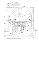
以下、図面を参照して本発明の実施例1を説明する。図1は、基板処理装置の概略構成図である。図2(a)は、開状態の開閉弁9を示す縦断面図である。図2(b)は、弁体41から見た弁座ブロック31を示す平面図である。図3は、閉状態の開閉弁9を示す縦断面図である。
Hereinafter, a first embodiment of the present invention will be described with reference to the drawings. FIG. 1 is a schematic configuration diagram of the substrate processing apparatus. FIG. 2A is a longitudinal sectional view showing the on-off
<基板処理装置1の構成>
図1を参照する。基板処理装置1は、略水平姿勢で基板Wを保持して、保持した基板Wを回転させる保持回転部2を備えている。保持回転部2は、例えば真空吸着により基板Wの裏面を保持するスピンチャック3と、鉛直方向の回転軸AX1周りにスピンチャック3を回転させる回転駆動部4とを備えている。回転駆動部4は、電動モータを備えている。
<Configuration of
Please refer to FIG. The
また、基板処理装置1は、ノズル5、処理液供給源6、処理液配管7、ポンプP、開閉弁9および制御部10を備えている。
The
ノズル5は、保持回転部2で保持された基板W上に処理液を吐出するものである。処理液は、例えば、フォトレジスト液または反射防止膜形成用の液などの塗布液、シンナー等の溶剤、純水(例えばDIW)、現像液、エッチング液が用いられる。処理液供給源6は、例えば、処理液を収容するタンクやボトルで構成される。処理液配管7は、ノズル5と処理液供給源6との間で処理液を通すものである。なお、処理液は、本発明の液体に相当する。
The
処理液配管7には、ポンプPと開閉弁9が設けられている。なお、処理液配管7には、フィルタその他の構成が設けられていてもよい。ポンプPは、処理液供給源6から処理液を吸引して、吸引した処理液をノズル5方向に送り出すものである。開閉弁9は、処理液の供給およびその供給の停止を行う。電流供給回路11は、開閉弁本体9Aに電流(電力)を供給するものである。電流供給回路11には、図示しない電源から電力が供給される。
The processing liquid pipe 7 is provided with a pump P and an on-off
制御部10は、1つ以上の中央演算処理装置(CPU)を備えている。制御部10は、開閉弁9を含む基板処理装置1の各構成を制御する。また、制御部10は、図示しない記憶部に記憶された例えば各種条件やプログラムに基づいて基板処理を実行する。なお、記憶部は、例えば、ROM(Read-only Memory)、RAM(Random-Access Memory)、およびハードディスクの少なくともいずれか1つを備えている。
The
<開閉弁9の構成>
次に、図2(a)、図2(b)、図3を参照して、本発明の特徴部分である開閉弁9を説明する。開閉弁9は、流路ブロック21(ボディとも言う)とハウジング22とを備えている。流路ブロック21は、弁室内流路23、上流側流路25および下流側流路27を備えている。弁室内流路23、上流側流路25および下流側流路27は各々、処理液を通すものである。上流側流路25および下流側流路27は各々、弁室内流路23に連通する。
<Configuration of on-off
Next, the on-off
なお、上流側流路25が本発明の第1流路に相当する。下流側流路27が本発明の第2流路に相当する。
Note that the
また、流路ブロック21は、弁座ブロック31を備えている。弁座ブロック31は、弁座部35と永久磁石部36を備えている。弁座部35は、弁室内流路23と下流側流路27との境界となる開口37の周りを取り囲んでいる。弁座部35は、弁室内流路23内に設けられている。また、弁座部35は、開口37の半径方向に延びるようにリング状に形成されている。図2(b)は、弁体41から見た弁座ブロック31を示す平面図である。
The flow path block 21 includes a
永久磁石部36は、下流側流路27の周りを取り囲み、弁座部35側に設けられている。永久磁石は、例えばフェライト磁石またはネオジム磁石が用いられる。ここで、弁座部35と永久磁石部36の関係を説明する。永久磁石部36の全ての面は、例えば、PFA(パーフルオロアルコキシアルカン:perfluoroalkoxyalkane)のカバー38で覆われている。カバー38は、所望の厚みで形成されたシートまたは膜で構成されている。弁座部35は、カバー38の一部である。すなわち、カバー38の内、後述する弁体41および電磁石部45に対向する平面部分が弁座部35となる。永久磁石部36は、弁座部35に隣接する。
The
永久磁石部36は、例えば、図2(a)の上側(弁座部35側)がN極、図2(a)の下側(弁座部35の反対側)がS極になるように、構成されている。なお、その逆の配置となるように、永久磁石部36が構成されていてもよい。すなわち、上側がS極、かつ下側がN極になるように、永久磁石部36が構成されてもよい。
The
可動部33は、弁室内流路23およびハウジング22に跨がって配置される。可動部33は、弁体41、弁体側電磁石部43、弁棒45およびダイアフラム46を備えている。弁体41は、弁室内流路23内に設けられている。弁体41は、弁座部35に接触するためのものである。すなわち、弁体41は、弁座部35に接触して開口37を塞ぐものである。これにより、上流側流路25から下流側流路27への処理液の流れを止めることができる。
The
弁体41と弁体側電磁石部43の位置関係を説明する。図2(a)に示すように、弁体41は、弁座部35を挟んで永久磁石部36の反対側に設けられている。弁体側電磁石部43は、弁体41を挟んで弁座部35の反対側に設けられている。すなわち、弁体41および弁座部35は、弁体側電磁石部43と永久磁石部36との間に挟まれて配置されている。
The positional relationship between the
ここで、弁体41と弁体側電磁石部43の関係を説明する。弁体側電磁石部43の全ての面は、例えばPFAのカバー47で覆われている。カバー47は、所望の厚みで形成されたシートまたは膜で構成されている。弁体41は、カバー47の一部である。すなわち、カバー47の内、弁座部35および永久磁石部36に対向する平面部分が弁体41となる。弁体側電磁石部43は、弁体41と隣接する。弁棒45は、カバー47で覆われた弁体側電磁石部43と連結する。ハウジング22には、弁棒45を案内するためのガイド孔48が設けられている。
Here, the relationship between the
ガイド孔48には、弁棒45が収容される。弁棒45とガイド孔48との間には、隙間(遊び)49が形成されている。これにより、図2(a)に示す縦方向の軸AX2(または移動方向)に対して弁棒45(可動部33)を僅かに傾けることができる。すなわち、弁棒45(可動部33)は、弁体41をぐらつかせるために隙間を有してガイドされている。なお、軸AX2は、開口37または永久磁石部36の中心軸と平行でかつ開口37または永久磁石部36の中心軸を通過する。また、軸AX2は、図2(a)に示す弁座部35の上面と直交する。
The
ダイアフラム46は、本実施例では、弁室内流路23と弁棒45側の空間SPとを仕切るために用いられる。ダイアフラム46の外周縁は、弁室内流路23内の側壁21Aに取り付けられる。一方、ダイアフラム46の内周縁は、可動部33に取り付けられている。なお、図2(a)では、ダイアフラム46の内周縁は、カバー47と弁棒45との間に取り付けられている。ダイアフラム46は、柔軟な材料で形成されており、例えば、PTFE(ポリテトラフルオロエチレン:polytetrafluoroethylene)またはPFAなどのフッ素樹脂で形成されている。
In this embodiment, the
ハウジング22には、弁体側電磁石部43の上昇を受け止めるためのストッパ50が設けられている。例えば、図2に示すガイド孔48の端面を含む所定の部分がストッパ50として構成される。
The
弁体側電磁石部43は、ボビン51と、ボビン51に電線を巻き付けて形成されたコイル53と、ボビン51の中空部51Aに通された鉄心55とを備えている。ボビン51、コイル53および鉄心55は、例えばPTFEなどのフッ素樹脂またはその他樹脂で覆われている。この場合、コイル53への電流供給経路は確保される。
The valve body-
コイル53には、電流供給回路11から電流が供給されるように構成されている。電流供給回路11は、弁体側電磁石部43に第1方向の電流を供給する。第1方向とは、例えば、コイル53に巻き付けられた電線の両端のうち第1端部を正、かつ第2端部を負として電流を流したときの方向をいう。第1方向と逆方向の第2方向とは、例えば、コイル53に巻き付けられた電線の両端のうち第1端部を負、かつ第2端部を正として電流を流したときの方向をいう。なお、第1方向は、第1端部を負、かつ第2端部を正として流したときの方向であってもよい。
The current is supplied from the
電流供給回路11は、弁体側電磁石部43に第1方向の電流を供給し、永久磁石部36に弁体側電磁石部43を引き付けることで、弁座部35に弁体41を近づけさせて弁座部35に弁体41を押し付ける(図3参照)。また、電流供給回路11は、弁体側電磁石部43に第1方向と逆方向の第2方向の電流を供給し、永久磁石部36から弁体側電磁石部43を反発させることで、弁座部35から弁体41を離れさせる(図2(a)参照)。
The
<基板処理装置1および開閉弁9の動作>
次に、基板処理装置1および開閉弁9の動作を説明する。図示しない搬送機構は、図1に示す保持回転部2上に基板Wを搬送する。スピンチャック3は、基板Wの裏面を吸着して基板Wを保持する。回転駆動部4は、スピンチャック3を回転軸AX1周りに回転させる。これにより、予め設定されたタイミング、回転速度および期間で、スピンチャック3に保持された基板Wは回転される。図示しないノズル移動機構は、基板Wの中心の上方にノズル5を移動させる。
<Operation of
Next, operations of the
〔ステップS01〕開閉弁9(閉状態)
この時点では、開閉弁9は閉じられており、ノズル5から処理液が吐出されていない。図3に示すように、弁体41は弁座部35に押し当てられており、上流側流路25と下流側流路27との間の処理液の流れが停止している。この際、電流供給回路11は、弁体側電磁石部43に第1方向の電流を供給している。そのため、弁体側電磁石部43の弁体41側がS極となっており、弁体側電磁石部43と永久磁石部36は、互いに引き付け合っている。
[Step S01] On-off valve 9 (closed state)
At this time, the on-off
〔ステップS02〕開閉弁9を開状態にする
ノズル5から処理液を吐出するために、電流供給回路11は、弁体側電磁石部43に第1方向と逆方向である第2方向に電流を供給する。これにより、図2(a)に示すように、弁体側電磁石部43の弁体41側(下側)がN極となり、弁体側電磁石部43と永久磁石部36は、互いに反発する。そのため、弁体41が弁座部35から離れる。その後、弁体側電磁石部43と連結する弁棒45の裏面45Aがストッパ50に接触し、弁体41と弁座部35との間が所定の距離に保たれた状態で、弁体側電磁石部43がストッパ50側に位置する。
[Step S02] Opening the open /
これにより、上流側流路25と下流側流路27との間で処理液を流すことができる。すなわち、ポンプPは、処理液供給源6から処理液を吸引し、開閉弁9の方向に処理液を送り出す。開閉弁9において、上流側流路25に送られた処理液は、順番に、弁室内流路23、下流側流路27に送られる。開閉弁9を通過した処理液は、ノズル5に送られ、ノズル5から基板W上に処理液が吐出される。
This allows the processing liquid to flow between the
〔ステップS03〕開閉弁9を閉状態にする
ノズル5から処理液を吐出し、予め設定された時間が経過した後に、ノズル5からの処理液の吐出を停止する。この動作を説明する。電流供給回路11は、弁体側電磁石部43に第1方向の電流を供給する。これにより、図3に示すように、弁体側電磁石部43の弁体41側(下側)がS極となり、弁体側電磁石部43と永久磁石部36は、互いに引き付け合う。そのため、弁座部35に弁体41が近づけられて弁座部35に弁体41が押し付けられる。弁体41と弁座部35は、弁体側電磁石部43と永久磁石部36によって挟まれている。そのため、弁体側電磁石部43および永久磁石部36で生じた磁界(または磁力)は、弁座部35および開口37の周方向に均一に、弁体41を弁座部35に押し付けようとする。そのため、弁体41と弁座部35の接触を確実にすることができる。
[Step S03] Close the on-off
また、弁座部35に弁体41を押し付ける際に、弁体41と弁座部35の間の接触は、平面同士で行われる。弁体41および弁座部35の接触面が共に平面である。そのため、接触時の衝撃力(単位面積当たり)および弁座部に弁体を押し付ける力(単位面積当たり)を分散させることができるので、パーティクルの発生を抑えることができる。
Further, when the
また、弁体41と弁座部35は共に、PFAで形成されている。弁体41または弁座部35が例えばPTFEで形成されていると、それらを接触させることでパーティクルが発生する可能性がある。PFAは、接触によるパーティクルが発生しにくい材料である。そのため、PFAで共に形成された弁体41と弁座部35を接触させたときに、パーティクルの発生を抑えることができる。
The
弁体41を弁座部35に押し付けると、上流側流路25と下流側流路27の間の処理液の流通が停止する。これにより、ノズル5からの処理液の吐出が停止される。ノズル5は、基板Wの上方の位置から待機位置に移動される。基板Wが回転している場合、基板Wの回転は停止される。その後、スピンチャック3は、基板Wの裏面の吸着を解除し、図示しない搬送機構は、スピンチャック3(保持回転部2)上から基板Wを搬送する。
When the
本実施例によれば、弁体41側には弁体側電磁石部43が設けられ、弁座部35側には永久磁石部36が設けられている。電流供給回路11が弁体側電磁石部43に第1方向の電流を供給すると、弁体側電磁石部43は磁界を生成する。そのため、弁体側電磁石部43は、永久磁石部36に引き付けられる。すなわち、弁体41と弁座部35には、磁界による引き付け合う力が働く。これにより、弁座部35に弁体41が近づけられ、弁座部35に弁体41が押し付けられる。仮に弁体41が弁座部35に片当たりしても、引き付け合う力によって、片当たりしていない弁体41部分にも弁座部35に接触しようとする力が働く。すなわち、弁座部35の周方向に均一に弁体41を弁座部35に押し付けることができる。これにより、弁体41と弁座部35との接触を確実にすることができ、リーク発生を防止することができる。
According to the present embodiment, the valve body-
また、図12に示す開閉弁を駆動させる電動モータ109は、比較的発熱し易く、発熱によって生じた熱は、電動モータ109の出力からダイアフラム106に伝わって、開閉弁9を通過する処理液に影響を与える可能性がある。弁体41を含む可動部33は、弁体側電磁石部43よって移動されるが、電磁石は、電動モータ109に比べて発熱が抑えられる。そのため、本発明は、発熱によって処理液に与える影響を抑えることができる。
Further, the
なお、図12に示す電動モータで駆動される開閉弁および図13に示す電磁弁201は、可動鉄心203(可動部材)の一端で駆動して、可動鉄心203の他端で弁座208に接触および接触解除を行っている。そのため、可動鉄心203を弁座208に片当たりさせないために、厳密な組み立て精度を必要とする。しかしながら、弁体41側には、弁体側電磁石部43が設けられ、弁座部35側には、永久磁石部36が設けられている。これにより、弁体41と弁座部35との接触を確実にすることができるので、本発明は、厳密な組み立て精度を必要としなくてもよい。そのため、組み立てを容易に行うことができる。
The on-off valve driven by the electric motor shown in FIG. 12 and the
また、電流供給回路11は、弁体側電磁石部43に第1方向と逆方向の第2方向の電流を供給し、永久磁石部36から弁体側電磁石部43を反発させることで、弁座部35から弁体41を離れさせる。これにより、弁体側電磁石部43により生成された磁界によって、弁座部35に弁体41を近づけて弁座部35に弁体41を押し付けことができると共に、弁座部35から弁体41を離すことができる。
Further, the
また、弁座ブロック31が永久磁石部36を備えている。例えば、弁座部35側の永久磁石部36が電磁石である場合、弁体側電磁石部43および弁座部側電磁石部の両方で磁界を発生させることできる。しかしながら、弁体41側に加えて弁座部35側が電磁石であると、構造が複雑になる。また、弁体側電磁石部43に加えて弁座部側電磁石部で発熱することになる。本実施例によれば、弁座ブロック31は永久磁石部36を備えているので、構成をシンプルにでき、また、弁座部側の永久磁石部36は発熱しないので、発熱を抑えることができる。
Further, the
次に、図面を参照して本発明の実施例2を説明する。なお、実施例1と重複する説明は省略する。図4(a)は、開状態の開閉弁9を示す縦断面図である。図4(b)は、閉状態の開閉弁9の一部を示す縦断面図である。
Next, a second embodiment of the present invention will be described with reference to the drawings. Note that the description overlapping with the first embodiment will be omitted. FIG. 4A is a longitudinal sectional view showing the on-off
実施例1では、弁座ブロック31は永久磁石部36を備え、可動部33は弁体側電磁石部43を備えていた。この点、本実施例では、図4(a)に示すように、弁座ブロック31は弁座部側電磁石部61を備え、可動部33は永久磁石部63を備えている。
In the first embodiment, the
図4(a)を参照する。本実施例の開閉弁9は、処理液を通す弁室内流路23と、弁室内流路23に各々連通する上流側流路25および下流側流路27とを備えている。また、開閉弁9は、弁座ブロック31、可動部33および電流供給回路11を備えている。
Referring to FIG. The on-off
弁座ブロック31は、弁座部35と弁座部側電磁石部61を備えている。弁座部35は、弁室内流路23と下流側流路27との境界となる開口37の周りを取り囲んでいる。弁座部35は、弁室内流路23内に設けられている。弁座部35は、弁座部側電磁石部61の全ての面を覆うカバー38の一部である。弁座部側電磁石部61は、下流側流路27の周りを取り囲み、弁座部35側に設けられている。弁座部側電磁石部61は、弁座部35に隣接する。
The
弁座部側電磁石部61は、中空部65Aに下流側流路27を配置するボビン65と、ボビン65に電線を巻き付けて形成されたコイル66と、ボビン65の中空部65Aに通された中空鉄心67とを備えている。中空鉄心67は円筒状で形成されており、中空鉄心67の中心軸部分の中空部には、下流側流路27が配置される。ボビン65、コイル66および中空鉄心67は、例えばPTFEなどのフッ素樹脂またはその他樹脂で覆われている。この場合も、コイル66への電流供給経路は確保される。
The valve seat
可動部33は、弁体41と永久磁石部63を備えている。弁体41は、カバー47の一部で構成されている。永久磁石部63は、弁体41側に設けられている。また、永久磁石部63は、弁体41に隣接する。
The
永久磁石部63は、例えば、図4(a)の上側(弁体41の反対側)がS極、図4(a)の下側(弁体41側)がN極になるように、構成されている。電流供給回路11は、弁座部側電磁石部61に第1方向および、第1方向と逆方向である第2方向の電流を選択的に供給する。
The
<開閉弁9を閉状態にする動作>
図4(a)において、開閉弁9は開状態である。開閉弁9を閉状態にするために、電流供給回路11は、弁座部側電磁石部61に第1方向の電流を供給する。これにより、図4(b)に示すように、弁座部側電磁石部61の上側(弁座部35側)がS極となり、下側(弁座部35の反対側)がN極となる。そのため、永久磁石部63と弁座部側電磁石部61は、互いに引き付け合う。これにより、弁座部35に弁体41を近づけさせて弁座部35に弁体41を押し付ける。そのため、上流側流路25と下流側流路27との間における処理液の流通が停止される。
<Operation to close the on-off
In FIG. 4A, the on-off
<開閉弁9を開状態にする動作>
図4(b)において、開閉弁9は閉状態である。開閉弁9を開状態にするために、電流供給回路11は、弁座部側電磁石部61に第2方向の電流を供給する。これにより、図4(a)に示すように、弁座部側電磁石部61の上側(弁座部35側)がN極となり、下側(弁座部35の反対側)がS極となる。そのため、永久磁石部63と弁座部側電磁石部61は、互いに反発し合う。これにより、弁座部35から弁体41を離れさせる。そのため、上流側流路25と下流側流路27との間において、処理液が流通される。
<Operation to open /
In FIG. 4B, the on-off
本実施例によれば、弁体41側には永久磁石部63が設けられ、弁座部35側には弁座部側電磁石部61が設けられている。電流供給回路11が弁座部側電磁石部61に第1方向の電流を供給すると、弁座部側電磁石部61は磁界を生成する。そのため、弁座部側電磁石部61は、永久磁石部63を引き付ける。すなわち、弁体41と弁座部35には、磁界による引き付け合う力が働く。これにより、弁座部35に弁体41が近づけられ、弁座部35に弁体41が押し付けられる。仮に弁体41が弁座部35に片当たりしても、引き付け合う力によって、片当たりしていない弁体41部分にも弁座部35に接触しようとする力が働く。すなわち、弁座部35の周方向に均一に弁体41を弁座部35に押し付けることができる。これにより、弁体41と弁座部35との接触を確実にすることができ、リーク発生を防止することができる。
According to this embodiment, the
次に、図面を参照して本発明の実施例3を説明する。なお、実施例1,2と重複する説明は省略する。図5(a)は、開状態の開閉弁9を示す縦断面図である。図5(b)は、閉状態の開閉弁9の一部を示す縦断面図である。
Next, a third embodiment of the present invention will be described with reference to the drawings. Note that the description overlapping with the first and second embodiments will be omitted. FIG. 5A is a longitudinal sectional view showing the on-off
上述した実施例1では、図2(a)に示すように、弁座ブロック31は、永久磁石部36を備えていた。この点、永久磁石部36に代えて、弁座ブロック31は、強磁性体部71を備えていてもよい。
In the first embodiment described above, the
図5(a)において、弁座ブロック31は、弁座部35と強磁性体部71を備えている。強磁性体部71は、下流側流路27の周りを取り囲み、弁座部35側に設けられている。強磁性体部71は、鉄、ニッケルおよびコバルトの少なくとも1つを含んで構成されている。強磁性体部71は、合金または酸化物であってもよい。強磁性体部71は、永久磁石でないものであるが、永久磁石であってもよい。
5A, the
可動部33は、実施例1と同様に、弁体41と弁体側電磁石部43を備えている。本変形例においては、可動部33は、ばね部材73が取り付けられている。ばね部材73は、例えば、可動部33を吊り下げるように、ハウジング22の弁座部35に対向する面22Aに取り付けられている。なお、図5(a)において、可動部33を吊り下げるために、2つのばね部材73が設けられているが、1つまたは3以上のばね部材73が設けられていてもよい。
The
電流供給回路11は、第1方向(または第2方向)の電流を弁体側電磁石部43に供給するものである。電流供給回路11が弁体側電磁石部43に電流を供給していないときに(弁体側電磁石部43が磁界を生成していないときに)、ばね部材73は可動部33をストッパ50に押し付ける。電流供給回路11が弁体側電磁石部43に電流を供給すると、弁体側電磁石部43は磁界を生成し、生成された磁界は、ばね部材73の復元力に反しながら、弁体41を含む可動部33を弁座部35に近づける方向に移動させる。電流供給回路11が弁体側電磁石部43に供給していた電流を停止させると、弁体側電磁石部43は磁界を生成しなくなり、ばね部材73の反発力によって、弁体41を含む可動部33が弁座部35から遠ざける方向に移動させる。
The
<開閉弁9を閉状態にする動作>
図5(a)において、開閉弁9は開状態である。開閉弁9を閉状態にするために、電流供給回路11は、弁体側電磁石部43に第1方向の電流を供給する。これにより、図5(b)に示すように、弁体側電磁石部43の下側(弁体41側)がS極(またはN極)となる。そのため、弁体側電磁石部43が強磁性体部71に引き付けられる。これにより、ばね部材73にエネルギを蓄積させつつ(すなわち、ばね部材73の復元力に抵抗しつつ)弁座部35に弁体41を近づけさせて弁座部35に弁体41を押し付ける。そのため、上流側流路25と下流側流路27との間における処理液の流通が停止される。
<Operation to close the on-off
In FIG. 5A, the on-off
<開閉弁9を開状態にする動作>
図5(b)において、開閉弁9は閉状態である。開閉弁を開状態にするために、電流供給回路11は、弁体側電磁石部43への第1方向の電流の供給を停止する。これにより、図5(a)に示すように、弁体側電磁石部43が磁界を生成しなくなり、ばね部材73に蓄積されたエネルギ(すなわち復元力)によって弁座部35から弁体41を離れされる。そのため、上流側流路25と下流側流路27との間において、処理液が流れる。また、ばね部材73は可動部33をストッパ50に押し付けるので、開状態の弁体41の位置を安定させることができる。
<Operation to open /
In FIG. 5B, the on-off
本実施例によれば、弁体側電磁石部43により生成される磁界とばね部材73に蓄積されるエネルギとによって、弁座部35に弁体41を近づけて弁座部35に弁体41を押し付けことができると共に、弁座部35から弁体41を離すことができる。
According to the present embodiment, the
次に、図面を参照して本発明の実施例4を説明する。なお、実施例1から3と重複する説明は省略する。図6(a)は、開状態の開閉弁9を示す縦断面図である。図6(b)は、閉状態の開閉弁9の一部を示す縦断面図である。
Next, a fourth embodiment of the present invention will be described with reference to the drawings. The description overlapping with the first to third embodiments will be omitted. FIG. 6A is a longitudinal sectional view showing the on-off
上述した実施例2では、図4(a)に示すように、可動部33は、永久磁石部63を備えていた。この点、永久磁石部63に代えて、可動部33は、強磁性体部75を備えていてもよい。
In the above-described second embodiment, as shown in FIG. 4A, the
図6(a)において、可動部33は、弁体41と強磁性体部75を備えている。強磁性体部75は、弁体41側に設けられている。弁体41および弁座部35は、強磁性体部75と弁座部側電磁石部61との間に挟まれて配置されている。強磁性体部75は、実施例3の強磁性体部71と同様に、鉄などで構成されている。強磁性体部75は、永久磁石でないものであるが、永久磁石であってもよい。
6A, the
可動部33は、実施例3と同様に、ばね部材73が取り付けられている。電流供給回路11は、第1方向(または第2方向)の電流を弁座部側電磁石部61に供給するものである。電流供給回路11が弁座部側電磁石部61に電流を供給すると、弁座部側電磁石部61は磁界を生成し、生成された磁界は、ばね部材73の復元力に反しながら、弁体41を含む可動部33を弁座部35に近づける方向に移動させる。また、電流供給回路11が弁座部側電磁石部61への電流の供給を停止すると、弁座部側電磁石部61は磁界を生成しなくなり、ばね部材73の反発力は、弁体41を含む可動部33を弁座部35から遠ざける方向に移動させる。
The
<開閉弁9を閉状態にする動作>
図6(a)において、開閉弁9は開状態である。開閉弁9を閉状態にするために、電流供給回路11は、弁座部側電磁石部61に第1方向の電流を供給する。これにより、図6(b)に示すように、弁座部側電磁石部61の上側(弁座部35側)がS極(またはN極)となる。そのため、弁座部側電磁石部61に強磁性体部75を引き付ける。これにより、ばね部材73にエネルギを蓄積させつつ弁座部35に弁体41を近づけさせて弁座部35に弁体41を押し付ける。そのため、上流側流路25と下流側流路27との間における処理液の流通が停止される。
<Operation to close the on-off
In FIG. 6A, the on-off
<開閉弁9を開状態にする動作>
図6(b)において、開閉弁9は閉状態である。開閉弁9を開状態にするために、電流供給回路11は、弁座部側電磁石部61への第1方向の電流の供給を停止する。これにより、図6(a)に示すように、弁座部側電磁石部61が磁界を生じさせなくなり、ばね部材73に蓄積されたエネルギによって弁座部35から弁体41が離れる。そのため、上流側流路25と下流側流路27との間において処理液が流れる。また、ばね部材73は可動部33をストッパ50に押し付けるので、開状態の弁体41の位置を安定させることができる。
<Operation to open /
In FIG. 6B, the on-off
本実施例によれば、弁座部側電磁石部61により生成される磁界とばね部材73に蓄積されるエネルギとによって、弁座部35に弁体41を近づけて弁座部35に弁体41を押し付けことができると共に、弁座部35から弁体41を離すことができる。
According to the present embodiment, the
次に、図面を参照して本発明の実施例5を説明する。なお、実施例1,2と重複する説明は省略する。図7(a)は、開状態の開閉弁9を示す縦断面図である。図7(b)は、閉状態の開閉弁9の一部を示す縦断面図である。
Next, a fifth embodiment of the present invention will be described with reference to the drawings. Note that the description overlapping with the first and second embodiments will be omitted. FIG. 7A is a longitudinal sectional view showing the on-off
上述した実施例1,2では、図2(a)、図4(a)に示すように、弁座ブロック31および可動部33の一方が電磁石部を備え、それらの他方が永久磁石部を備えていた。この点、弁座ブロック31および可動部33は共に、電磁石部を備えていてもよい。
In
図7(a)において、弁座ブロック31は、実施例2と同様に、弁座部35と弁座部側電磁石部61を備えている。また、可動部33は、実施例1と同様に、弁体41と弁体側電磁石部43を備えている。
In FIG. 7A, the
電流供給回路11は、弁体側電磁石部43および弁座部側電磁石部61に電流を供給する。弁体側電磁石部43および弁座部側電磁石部61への電流の供給量は各々、調整される。電流供給回路11は、2つの電磁石部43,61に電流を供給する動作をするために、例えば、弁体側電磁石部43および弁座部側電磁石部61のいずれか一方を永久磁石のように使用する。
The
すなわち、電流供給回路11は、弁体側電磁石部43に予め設定された方向(第1方向または第2方向)の電流を供給する。これにより、例えば、図7(a)の上側(弁体41側)がS極、図7(a)の下側(弁体41の反対側)がN極になるように、弁体側電磁石部43は磁界を生成する。
That is, the
これに対し、電流供給回路11は、弁座部側電磁石部61に第1方向の電流を供給する。これにより、図7(b)に示すように、弁座部側電磁石部61の上側(弁座部35側)がS極となり、下側(弁座部35の反対側)がN極となる。そのため、弁体側電磁石部43と弁座部側電磁石部61は、互いに引き付け合う。
On the other hand, the
また、電流供給回路11は、弁座部側電磁石部61に第2方向の電流を供給する。これにより、図7(a)に示すように、弁座部側電磁石部61の上側(弁座部35側)がN極となり、下側(弁座部35の反対側)がS極となる。そのため、弁体側電磁石部43と弁座部側電磁石部61は、互いに反発し合う。
The
この電流供給回路11の動作は、弁体側電磁石部43を永久磁石として使用した場合を説明したものである。弁座部側電磁石部61を永久磁石として使用した場合の電流供給回路11の動作も同様に行われる。
The operation of the
本実施例によれば、弁体側電磁石部43および弁座部側電磁石部61の両方で磁界を発生させることできる。また、弁体側電磁石部43および弁座部側電磁石部61の各々で発生させる磁界の強さを調整することができる。更に、弁体側電磁石部43および弁座部側電磁石部61の各々で生成された磁界によって、弁座部35に弁体41を近づけて弁座部35に弁体41を押し付けことができると共に、弁座部35から弁体41を離すことができる。
According to the present embodiment, it is possible to generate a magnetic field in both the valve body
本発明は、上記実施形態に限られることはなく、下記のように変形実施することができる。 The present invention is not limited to the above embodiment, but can be modified as follows.
(1)上述した実施例1,2,5では、開閉弁9が開状態のときに、可動部33をストッパ50に押し当てており、弁体41と弁座部35との間の隙間(開度)は、一定であった。この点、弁体側電磁石部43および弁座部側電磁石部61の少なくとも一方に供給する電流量を調整することで、弁体41と弁座部35の間の隙間を調整するようにしてもよい。
(1) In the first, second, and fifth embodiments, when the on-off
例えば、電流供給回路11は、弁体側電磁石部43に第2方向の電流を供給する際に、弁体側電磁石部43に供給する電流量を調整することで、弁座部35と弁体41の間の隙間を調整する。これにより、開閉弁9が開状態のときの、上流側流路25と下流側流路27の間に流れる処理液の流量を調整することができる。ここで、第2方向の電流とは、図8(a)の開閉弁9において、弁体側電磁石部43と永久磁石部36を互いに反発させるための方向の電流である。
For example, the
例えば、図8(a)のように、弁体側電磁石部43と永久磁石部36を反発させて、可動部33をストッパ50に押し当てているときに、弁体41と弁座部35の間の隙間が距離D1であり、弁体側電磁石部43に供給される電流量が電流量CA1(絶対値)であるとする。弁体41と弁座部35の間の隙間を、距離D1よりも狭い距離D2にする場合(D1>D2)、電流供給回路11は、弁体側電磁石部43に供給する電流量を、電流量CA1よりも少ない電流量CA2(絶対値)に調整する(CA1>CA2)。
For example, as shown in FIG. 8A, when the
なお、図7(a)のように、開閉弁9が弁体側電磁石部43と弁座部側電磁石部61とを備える場合は、弁体側電磁石部43と弁座部側電磁石部61の少なくとも一方に供給する電流量を調節することで、弁体41と弁座部35の間の隙間を調整するようにしてもよい。
When the on-off
また、図8(a)において、弁室内流路23内の処理液が弁体41と弁座部35の間を通過して下流側流路27に流れる際に、弁体41と弁座部35の間を押し広げる可能性がある。これを抑えるために、例えば、図8(b)のように、可動部33の上昇を抑えるための上昇抑え部76を設けてもよい。上昇抑え部76は、接触部77とばね部材78を備えている。ばね部材78は、ハウジング22と接触部77に接続されており、可動部33には接続されていない。そのため、上昇抑え部76は、弁体41と弁座部35とが接触しているときには、機能せず、弁座部35から弁体41を離した際に機能させる。上昇抑え部76は、弁体41と弁座部35の間を押し広げる力を抑え、弁体41と弁座部35との間の隙間の変動を抑えることができる。
8A, when the processing liquid in the valve
また、図8(b)の上昇抑え部76に代えて、図9に示す、可動部33に接触させるネジ79によって、弁体41と弁座部35の間の隙間を変化させてもよい。すなわち、ネジ79は、ハウジング22に設けられたネジ穴80に通されており、ネジ79のねじ山とネジ穴80のねじ山とが噛み合わされる。ネジ79の一端にはつまみ79Aが設けられ、他端が弁棒45(可動部33)と接触する接触面79Bが設けられている。ネジ79を回すと、ネジ79がネジ穴80に対して上または下に移動する。すなわち、ネジ79を回すと、接触面79Bの高さ位置を変化させることができる。
9B, the gap between the
閉状態から開状態にする際に、電流供給回路11は、弁体側電磁石部43に第2方向の電流を供給し、弁体側電磁石部43と永久磁石部36とを互いに反発させる。これにより、弁座部35から弁体41を離れさせ、その後、弁棒45の上面45Bが、ネジ79により高さ位置が調整された接触面79Bに押し当てられる。ネジ79の接触面79Bに弁棒45の上面45Bが接触された高さ位置によって、弁体41と弁座部35の間の隙間が設定される。
When the state is changed from the closed state to the open state, the
(2)上述した各実施例および変形例(1)では、ダイアフラム46は、弁体41と個別に設けられていた。この点、図10(a)〜図10(c)に示すように、ダイアフラム81は、弁室内流路23と空間SPの間を仕切るだけでなく、弁体としても機能させてもよい。ダイアフラム81の弁体部分を符号83で表す。
(2) In each of the above embodiments and modified examples (1), the
なお、図10(a)では、ダイアフラム81は、弁体側電磁石部43の弁座部35と対向する下面、および側面に接合されている。また、図10(b)では、ダイアフラム81は、弁体側電磁石部43の側面に接合されずに、弁体側電磁石部43の弁座部35と対向する下面に接合されている。また、図10(c)では、ダイアフラム81の弁体83の部分が弁体83以外の部分の厚みよりも厚く構成されていてもよい。図10(a)〜図10(c)において、ダイアフラム81は、弁体側電磁石部43と接合されるが、開閉弁9の構成に応じて、永久磁石部36または強磁性体部75に交換してもよい。
In FIG. 10A, the
(3)上述した各実施例および各変形例では、弁体側電磁石部43および弁座部側電磁石部61の鉄心55および中空鉄心67は、軸方向に直径が同じとなるように構成されていた。この点、鉄心55および中空鉄心67は、図11(a)、図11(b)のように、弁座部35と対向する端部で、各ボビン51,65の内径IDよりも大きい直径を有する対向部85,86が設けられてもよい。対向部85,86は、例えば、鉄心55および中空鉄心67と同じ鉄を含む材料で構成されている。図11(a)は、弁体側電磁石部43を示す図である。図11(b)は、弁座部側電磁石部61を示す図である。なお、対向部86は、リング状に形成されている。また、対向部85,86は各々、鉄心55または中空鉄心67の一部として設けられているが、鉄心55および中空鉄心67とそれぞれ個別に設けられていてもよい。
(3) In each of the above-described embodiments and modifications, the
(4)上述した各実施例および各変形例では、弁体41と弁座部35の間の接触を、平面同士で行っていた。この点、例えば、パーティクルの発生が殆どない場合は、図2(a)のような縦断面図において、弁体41と弁座部35のいずれか一方を点接触させてもよい。
(4) In each of the embodiments and the modifications described above, the contact between the
(5)上述した各実施例および各変形例では、永久磁石部36,63は各々、1つの永久磁石で構成されていたが、例えば、リング状に配置された複数(例えば3つ以上)の永久磁石で構成されていてもよい。また、弁体側電磁石部43および弁座部側電磁石部61は各々、1つの電磁石で構成されていたが、例えば、リング状に配置された複数の電磁石で構成されていてもよい。さらに、強磁性体部71,75は各々、1つの強磁性体で構成されていたが、例えば、リング状に配置された複数の強磁性体で構成されていてもよい。
(5) In each of the embodiments and the modifications described above, each of the
(6)上述した各実施例および各変形例では、例えば図2(a)において、上流側流路25から下流側流路27に処理液を流していたが、下流側流路27から上流側流路25に処理液を流してもよい。
(6) In each of the above-described embodiments and modifications, for example, in FIG. 2A, the processing liquid flows from the
(7)上述した各実施例および各変形例では、例えば図2(a)において、永久磁石部36および弁体側電磁石部43は各々、全面がカバー38,47で覆われていた。この点、永久磁石部36および弁体側電磁石部43は各々、弁座部35または弁体41に対応する部分だけカバー38,47で覆われていてもよい。また、弁座ブロック21がPFAで形成される場合、永久磁石部36は、弁座ブロック21に埋め込まれていてもよい。また、弁体側電磁石部43のボビン51、コイル53および鉄心55が、PFAに埋め込まれていてもよい。
(7) In the above-described embodiments and modifications, for example, in FIG. 2A, the entire surface of the
(8)上述した各実施例および各変形例では、例えば図2(a)において、永久磁石部36は、弁座部35の下側に設けられていたが、弁座部35の側方に設けられていてもよい。また、弁体側電磁石部43は、弁体41の上側に設けられていたが、弁体41の側方に設けられていてもよい。この場合、例えば、弁体側電磁石部43は中空鉄心を備えていてもよい。
(8) In the above-described embodiments and modifications, for example, in FIG. 2A, the
1 … 基板処理装置
5 … ノズル
P … ポンプ
9 … 開閉弁
10 … 制御部
11 … 電流供給回路
23 … 弁室内流路
25 … 上流側流路
27 … 下流側流路
31 … 弁座ブロック
33 … 可動部
35 … 弁座部
36,63 … 永久磁石部
37 … 開口
41,83 … 弁体
43 … 弁体側電磁石部
61 … 弁座部側電磁石部
71,75 … 強磁性体部
73 … ばね部材
DESCRIPTION OF
Claims (11)
前記弁室内流路に各々連通する第1流路および第2流路と、
前記弁室内流路と前記第2流路との境界となる開口の周りを取り囲み、前記弁室内流路に設けられた弁座部および、前記第2流路の周りを取り囲み、前記弁座部側に設けられた強磁性体部または磁石部を有する弁座ブロックと、
前記弁室内流路内に設けられ、前記弁座部に接触するための弁体および、前記弁体側に設けられた弁体側電磁石部を有する可動部と、
前記弁体側電磁石部に第1方向の電流を供給し、前記強磁性体部または前記磁石部に前記弁体側電磁石部を引き付けることで、前記弁座部に前記弁体を近づけさせて前記弁座部に前記弁体を押し付ける電流供給回路と、
を備えていることを特徴とする開閉弁。 A valve chamber passage through which liquid passes;
A first flow path and a second flow path each communicating with the valve chamber flow path;
The valve seat portion surrounding the opening which is a boundary between the valve chamber flow passage and the second flow passage, and surrounding the valve seat portion provided in the valve chamber flow passage, and the second flow passage; A valve seat block having a ferromagnetic portion or a magnet portion provided on the side,
A valve body provided in the valve chamber flow path, and a valve body for contacting the valve seat, and a movable unit having a valve body-side electromagnet unit provided on the valve body side,
By supplying a current in a first direction to the valve body-side electromagnet unit and attracting the valve body-side electromagnet unit to the ferromagnetic body unit or the magnet unit, the valve body is brought close to the valve seat unit, and the valve seat is brought close to the valve seat unit. A current supply circuit for pressing the valve body against the part,
An on-off valve characterized by comprising:
前記強磁性体部または前記磁石部は、前記磁石部であり、
前記電流供給回路は、前記弁体側電磁石部に第1方向の電流を供給し、前記磁石部に前記弁体側電磁石部を引き付けることで、前記弁座部に前記弁体を近づけて前記弁座部に前記弁体を押し付け、また、前記弁体側電磁石部に前記第1方向と逆方向の第2方向の電流を供給し、前記磁石部から前記弁体側電磁石部を反発させることで、前記弁座部から前記弁体を離れさせることを特徴とする開閉弁。 The on-off valve according to claim 1,
The ferromagnetic portion or the magnet portion is the magnet portion,
The current supply circuit supplies a current in a first direction to the valve body-side electromagnet unit, and attracts the valve body-side electromagnet unit to the magnet unit, thereby bringing the valve body close to the valve seat unit and the valve seat unit. The valve seat by pressing the valve body against the valve body and supplying a current in a second direction opposite to the first direction to the valve body-side electromagnet section to repel the valve body-side electromagnet section from the magnet section. An on-off valve, wherein the valve element is separated from a portion.
前記磁石部は、永久磁石部であることを特徴とする開閉弁。 The on-off valve according to claim 2,
The on-off valve, wherein the magnet unit is a permanent magnet unit.
前記磁石部は、弁座部側電磁石部であることを特徴とする開閉弁。 The on-off valve according to claim 2,
The said magnet part is a valve seat part side electromagnet part, The on-off valve characterized by the above-mentioned.
前記電流供給回路は、前記弁体側電磁石部に前記第2方向の電流を供給する際に、前記弁体側電磁石部に供給する電流量を調整することで、前記弁座部と前記弁体の間の隙間を調整することを特徴とする開閉弁。 The open / close valve according to any one of claims 2 to 4,
The current supply circuit adjusts an amount of current supplied to the valve body-side electromagnet portion when supplying the current in the second direction to the valve body-side electromagnet portion, so that the current between the valve seat portion and the valve body is adjusted. An on-off valve characterized by adjusting the gap between the valves.
前記強磁性体部または前記磁石部は、前記強磁性体部であり、
前記可動部は、ばね部材が取り付けられており、
前記電流供給回路は、前記弁体側電磁石部に第1方向の電流を供給し、前記磁石部に前記弁体側電磁石部を引き付けることで、前記ばね部材にエネルギを蓄積させつつ前記弁座部に前記弁体を近づけて、前記弁座部に前記弁体を押し付け、また、前記弁体側電磁石部に第1方向の電流の供給を停止することで、前記ばね部材に蓄積されたエネルギによって前記弁座部から弁体を離れさせることを特徴とする開閉弁。 The on-off valve according to claim 1,
The ferromagnetic portion or the magnet portion is the ferromagnetic portion,
The movable portion has a spring member attached thereto,
The current supply circuit supplies a current in a first direction to the valve body-side electromagnet section, and attracts the valve body-side electromagnet section to the magnet section, thereby accumulating energy in the spring member and applying the current to the valve seat section. By bringing the valve body close, pressing the valve body against the valve seat part, and stopping the supply of current in the first direction to the valve body-side electromagnet part, the energy stored in the spring member allows the valve seat part to move. An on-off valve characterized by separating a valve body from a part.
弁室内流路に各々連通する第1流路および第2流路と、
前記弁室内流路と前記第2流路との境界となる開口の周りを取り囲み、前記弁室内流路に設けられた弁座部および、前記第2流路の周りを取り囲み、前記弁座部側に設けられた弁座部側電磁石部を有する弁座ブロックと、
前記弁室内流路内に設けられ、前記弁座部に接触するための弁体および、前記弁体側に設けられた強磁性体部または磁石部を有する可動部と、
前記弁座部側電磁石部に第1方向の電流を供給し、前記弁座部側電磁石部に前記強磁性体部または前記磁石部を引き付けることで、前記弁座部に前記弁体を近づけさせて前記弁座部に前記弁体を押し付ける電流供給回路と、
を備えていることを特徴とする開閉弁。 A valve chamber passage through which liquid passes;
A first flow path and a second flow path each communicating with the valve chamber flow path;
The valve seat portion surrounding the opening which is a boundary between the valve chamber flow passage and the second flow passage, and surrounding the valve seat portion provided in the valve chamber flow passage, and the second flow passage; A valve seat block having a valve seat side electromagnet portion provided on the side,
A valve body provided in the valve chamber flow path, for contacting the valve seat portion, and a movable portion having a ferromagnetic material portion or a magnet portion provided on the valve body side,
By supplying a current in the first direction to the valve seat side electromagnet portion and attracting the ferromagnetic body portion or the magnet portion to the valve seat side electromagnet portion, the valve body is brought close to the valve seat portion. Current supply circuit for pressing the valve body against the valve seat portion,
An on-off valve characterized by comprising:
前記弁体および前記弁座部は、PFAで形成されていることを特徴とする開閉弁。 The on-off valve according to any one of claims 1 to 7,
The on-off valve, wherein the valve element and the valve seat are formed of PFA.
前記弁体と前記弁座部の間の接触は、平面同士で行われることを特徴とする開閉弁。 The open / close valve according to any one of claims 1 to 8,
The on-off valve according to claim 1, wherein the contact between the valve body and the valve seat portion is performed between flat surfaces.
前記ノズルに液体を送るポンプと、
前記ノズルと前記ポンプの間で液体を通す配管と、
前記配管に設けられ、前記ノズルへの液体の供給とその供給停止を選択できる開閉弁とを備え、
前記開閉弁は、液体を通す弁室内流路と、
前記弁室内流路に各々連通する第1流路および第2流路と、
前記弁室内流路と前記第2流路との境界となる開口の周りを取り囲み、前記弁室内流路に設けられた弁座部および、前記第2流路の周りを取り囲み、前記弁座部側に設けられた強磁性体部または磁石部を有する弁座ブロックと、
前記弁室内流路内に設けられ、前記弁座部に接触するための弁体および、前記弁体側に設けられた弁体側電磁石部を有する可動部と、
前記弁体側電磁石部に第1方向の電流を供給し、前記強磁性体部または前記磁石部に前記弁体側電磁石部を引き付けることで、前記弁座部に前記弁体を近づけさせて前記弁座部に前記弁体を押し付ける電流供給回路と、を備えていることを特徴とする基板処理装置。 A nozzle for discharging liquid,
A pump for sending liquid to the nozzle;
Piping for passing liquid between the nozzle and the pump;
An on-off valve provided on the pipe and capable of selecting supply of the liquid to the nozzle and supply stop thereof,
The on-off valve, a valve chamber flow path through which liquid passes,
A first flow path and a second flow path each communicating with the valve chamber flow path;
The valve seat portion surrounding the opening which is a boundary between the valve chamber flow passage and the second flow passage, and surrounding the valve seat portion provided in the valve chamber flow passage, and the second flow passage; A valve seat block having a ferromagnetic portion or a magnet portion provided on the side,
A valve body provided in the valve chamber flow path, and a valve body for contacting the valve seat, and a movable unit having a valve body-side electromagnet unit provided on the valve body side,
By supplying a current in a first direction to the valve body-side electromagnet part and attracting the valve body-side electromagnet part to the ferromagnetic body part or the magnet part, the valve body is brought close to the valve seat part, and the valve seat And a current supply circuit for pressing the valve body against the portion.
前記ノズルに液体を送るポンプと、
前記ノズルと前記ポンプの間で液体を通す配管と、
前記配管に設けられ、前記ノズルへの液体の供給とその供給停止を選択できる開閉弁とを備え、
前記開閉弁は、液体を通す弁室内流路と、
弁室内流路に各々連通する第1流路および第2流路と、
前記弁室内流路と前記第2流路との境界となる開口の周りを取り囲み、前記弁室内流路に設けられた弁座部および、前記第2流路の周りを取り囲み、前記弁座部側に設けられた弁座部側電磁石部を有する弁座ブロックと、
前記弁室内流路内に設けられ、前記弁座部に接触するための弁体および、前記弁体側に設けられた強磁性体部または磁石部を有する可動部と、
前記弁座部側電磁石部に第1方向の電流を供給し、前記強磁性体部または前記磁石部に前記弁座部側電磁石部を引き付けることで、前記弁座部に前記弁体を近づけさせて前記弁座部に前記弁体を押し付ける電流供給回路と、を備えていることを特徴とする基板処理装置。
A nozzle for discharging liquid,
A pump for sending liquid to the nozzle;
Piping for passing liquid between the nozzle and the pump;
An on-off valve provided on the pipe and capable of selecting supply of the liquid to the nozzle and supply stop thereof,
The on-off valve, a valve chamber flow path through which liquid passes,
A first flow path and a second flow path each communicating with the valve chamber flow path;
The valve seat portion surrounding the opening which is a boundary between the valve chamber flow passage and the second flow passage, and surrounding the valve seat portion provided in the valve chamber flow passage, and the second flow passage; A valve seat block having a valve seat side electromagnet portion provided on the side,
A valve body provided in the valve chamber flow path, for contacting the valve seat portion, and a movable portion having a ferromagnetic material portion or a magnet portion provided on the valve body side,
By supplying a current in a first direction to the valve seat side electromagnet portion and attracting the valve seat side electromagnet portion to the ferromagnetic material portion or the magnet portion, the valve body is brought close to the valve seat portion. And a current supply circuit for pressing the valve body against the valve seat.
Priority Applications (3)
| Application Number | Priority Date | Filing Date | Title |
|---|---|---|---|
| JP2018124922A JP2020003042A (en) | 2018-06-29 | 2018-06-29 | On-off valve and substrate processing apparatus equipped with this on-off valve |
| PCT/JP2019/019506 WO2020003795A1 (en) | 2018-06-29 | 2019-05-16 | Opening/closing valve and substrate processing device provided with said opening/closing valve |
| TW108117626A TWI715045B (en) | 2018-06-29 | 2019-05-22 | Switch valve and substrate processing device containing the switch valve |
Applications Claiming Priority (1)
| Application Number | Priority Date | Filing Date | Title |
|---|---|---|---|
| JP2018124922A JP2020003042A (en) | 2018-06-29 | 2018-06-29 | On-off valve and substrate processing apparatus equipped with this on-off valve |
Publications (1)
| Publication Number | Publication Date |
|---|---|
| JP2020003042A true JP2020003042A (en) | 2020-01-09 |
Family
ID=68984767
Family Applications (1)
| Application Number | Title | Priority Date | Filing Date |
|---|---|---|---|
| JP2018124922A Pending JP2020003042A (en) | 2018-06-29 | 2018-06-29 | On-off valve and substrate processing apparatus equipped with this on-off valve |
Country Status (3)
| Country | Link |
|---|---|
| JP (1) | JP2020003042A (en) |
| TW (1) | TWI715045B (en) |
| WO (1) | WO2020003795A1 (en) |
Cited By (1)
| Publication number | Priority date | Publication date | Assignee | Title |
|---|---|---|---|---|
| WO2024101403A1 (en) * | 2022-11-10 | 2024-05-16 | 株式会社堀場エステック | Fluid control valve and fluid control device |
Families Citing this family (1)
| Publication number | Priority date | Publication date | Assignee | Title |
|---|---|---|---|---|
| CN111425547B (en) * | 2020-05-19 | 2023-06-13 | 黄小伟 | Shock absorber built-in valve |
Family Cites Families (14)
| Publication number | Priority date | Publication date | Assignee | Title |
|---|---|---|---|---|
| JPS6046307B2 (en) * | 1976-04-19 | 1985-10-15 | 松下電器産業株式会社 | fluid flow control valve |
| JPS605163Y2 (en) * | 1980-03-13 | 1985-02-16 | 日本ランコ株式会社 | Solenoid valve control circuit |
| JPS5722482A (en) * | 1980-07-17 | 1982-02-05 | Matsushita Electric Ind Co Ltd | Coil driving type gas proportional control valve |
| JP3073177B2 (en) * | 1997-04-18 | 2000-08-07 | 東京計装株式会社 | Flow control valve and valve stem |
| UA67804C2 (en) * | 1998-10-02 | 2004-07-15 | Роналд Нортедж | Valve |
| CN2440139Y (en) * | 2000-08-02 | 2001-07-25 | 汪家藩 | Closed double-controll switch valve |
| KR101094271B1 (en) * | 2009-09-03 | 2011-12-19 | 양진우 | Valve using the polarity change and the interaction between the polarity of the permanent magnet |
| IT1401177B1 (en) * | 2010-07-28 | 2013-07-12 | Arag S R L | MEMBRANE VALVE WITH ELECTROMECHANICAL OPERATION, PARTICULARLY FOR DUCTS OF DERIVATION OF A FLUID OF SPRAYING AND / OR WEEDING AND SIMILAR SYSTEMS |
| EP2423545B8 (en) * | 2010-08-27 | 2012-11-28 | Coprececitec, S.L. | Gas valve |
| JP2015050348A (en) * | 2013-09-02 | 2015-03-16 | 東京エレクトロン株式会社 | Substrate processing apparatus, substrate processing method, and substrate processing recording medium |
| JP6442880B2 (en) * | 2014-06-16 | 2018-12-26 | アイシン精機株式会社 | Control valve |
| EP3280905B1 (en) * | 2015-04-10 | 2021-05-19 | Eugen Seitz AG | Gas injection valve for controlling a fluid flow |
| JP6593300B2 (en) * | 2016-10-25 | 2019-10-23 | 株式会社アドヴィックス | solenoid valve |
| CN108131456A (en) * | 2018-02-07 | 2018-06-08 | 厦门松霖科技股份有限公司 | Switch valve core and water outlet device |
-
2018
- 2018-06-29 JP JP2018124922A patent/JP2020003042A/en active Pending
-
2019
- 2019-05-16 WO PCT/JP2019/019506 patent/WO2020003795A1/en not_active Ceased
- 2019-05-22 TW TW108117626A patent/TWI715045B/en not_active IP Right Cessation
Cited By (1)
| Publication number | Priority date | Publication date | Assignee | Title |
|---|---|---|---|---|
| WO2024101403A1 (en) * | 2022-11-10 | 2024-05-16 | 株式会社堀場エステック | Fluid control valve and fluid control device |
Also Published As
| Publication number | Publication date |
|---|---|
| WO2020003795A1 (en) | 2020-01-02 |
| TW202001134A (en) | 2020-01-01 |
| TWI715045B (en) | 2021-01-01 |
Similar Documents
| Publication | Publication Date | Title |
|---|---|---|
| CN100434783C (en) | The electromagnetic valve | |
| JP6755290B2 (en) | Suction device and suction cup | |
| JP2023167590A (en) | lock actuator | |
| JP2008291911A (en) | Valve device | |
| WO2020003795A1 (en) | Opening/closing valve and substrate processing device provided with said opening/closing valve | |
| KR101492532B1 (en) | Solenoid valve | |
| JP2002188743A (en) | Self-retaining type solenoid valve | |
| JP2015121289A (en) | Electromagnetic valve device | |
| KR20110003767U (en) | valve | |
| JP6665068B2 (en) | Gas fuel supply device | |
| JPH11287346A (en) | Solenoid valve | |
| US20180038317A1 (en) | Gas fuel supply apparatus | |
| EP1679460B1 (en) | Valve | |
| JP6537808B2 (en) | solenoid valve | |
| JP2020128744A (en) | Solenoid pump | |
| JPH08200537A (en) | Solenoid | |
| WO2022270376A1 (en) | Mounting table and substrate processing device | |
| JPS5923451B2 (en) | self-holding electromagnetic device | |
| JPH11315953A (en) | Non-contact valve mechanism | |
| JP2022142303A (en) | solenoid valve | |
| JPH01234672A (en) | Solenoid valve | |
| JP5329183B2 (en) | Micro pump | |
| JP2007016935A (en) | Valve mechanism | |
| JPH11210918A (en) | Valve mechanism | |
| US10161532B2 (en) | Pinch valve assembly |