JP2020003594A - Image forming apparatus - Google Patents
Image forming apparatus Download PDFInfo
- Publication number
- JP2020003594A JP2020003594A JP2018121704A JP2018121704A JP2020003594A JP 2020003594 A JP2020003594 A JP 2020003594A JP 2018121704 A JP2018121704 A JP 2018121704A JP 2018121704 A JP2018121704 A JP 2018121704A JP 2020003594 A JP2020003594 A JP 2020003594A
- Authority
- JP
- Japan
- Prior art keywords
- heater
- period
- mode
- forming apparatus
- image forming
- Prior art date
- Legal status (The legal status is an assumption and is not a legal conclusion. Google has not performed a legal analysis and makes no representation as to the accuracy of the status listed.)
- Pending
Links
- 229910052736 halogen Inorganic materials 0.000 claims abstract description 80
- 150000002367 halogens Chemical class 0.000 claims abstract description 80
- 238000010438 heat treatment Methods 0.000 claims abstract description 43
- 230000001629 suppression Effects 0.000 claims description 21
- WFKWXMTUELFFGS-UHFFFAOYSA-N tungsten Chemical compound [W] WFKWXMTUELFFGS-UHFFFAOYSA-N 0.000 description 16
- 229910052721 tungsten Inorganic materials 0.000 description 16
- 239000010937 tungsten Substances 0.000 description 16
- 238000000034 method Methods 0.000 description 12
- 238000010586 diagram Methods 0.000 description 9
- 238000012546 transfer Methods 0.000 description 8
- 230000008020 evaporation Effects 0.000 description 7
- 238000001704 evaporation Methods 0.000 description 7
- 238000003384 imaging method Methods 0.000 description 6
- 230000002093 peripheral effect Effects 0.000 description 6
- 150000001875 compounds Chemical class 0.000 description 5
- 230000006870 function Effects 0.000 description 4
- 238000012545 processing Methods 0.000 description 4
- 230000007423 decrease Effects 0.000 description 3
- 239000000463 material Substances 0.000 description 3
- 239000003990 capacitor Substances 0.000 description 2
- 230000003111 delayed effect Effects 0.000 description 2
- 238000001514 detection method Methods 0.000 description 2
- 230000000694 effects Effects 0.000 description 2
- 230000005855 radiation Effects 0.000 description 2
- 230000002123 temporal effect Effects 0.000 description 2
- 230000007704 transition Effects 0.000 description 2
- WKBOTKDWSSQWDR-UHFFFAOYSA-N Bromine atom Chemical compound [Br] WKBOTKDWSSQWDR-UHFFFAOYSA-N 0.000 description 1
- 241001621399 Lampris Species 0.000 description 1
- 238000013459 approach Methods 0.000 description 1
- GDTBXPJZTBHREO-UHFFFAOYSA-N bromine Substances BrBr GDTBXPJZTBHREO-UHFFFAOYSA-N 0.000 description 1
- 229910052794 bromium Inorganic materials 0.000 description 1
- 239000003086 colorant Substances 0.000 description 1
- 238000004040 coloring Methods 0.000 description 1
- 238000012790 confirmation Methods 0.000 description 1
- 238000000354 decomposition reaction Methods 0.000 description 1
- 239000000284 extract Substances 0.000 description 1
- 230000005669 field effect Effects 0.000 description 1
- 239000000155 melt Substances 0.000 description 1
- 239000002244 precipitate Substances 0.000 description 1
- 238000001556 precipitation Methods 0.000 description 1
- 238000003825 pressing Methods 0.000 description 1
- 230000003134 recirculating effect Effects 0.000 description 1
- 230000001172 regenerating effect Effects 0.000 description 1
- 239000004065 semiconductor Substances 0.000 description 1
- 238000004904 shortening Methods 0.000 description 1
- -1 tungsten halide Chemical class 0.000 description 1
Images




Landscapes
- Fixing For Electrophotography (AREA)
Abstract
Description
本発明は、画像形成装置に関する。 The present invention relates to an image forming apparatus.
電子写真法によって用紙に画像を印刷する画像形成装置は、トナー像が転写された用紙を加熱する定着器を有している。加熱によって色材であるトナーが溶融して用紙に定着する。例えば、ローラ式の定着器は、加熱ローラと加熱ローラに当接してニップ部を形成する加圧ローラとを備え、ニップ部に送られてきた用紙を搬送しながら加熱する。加熱ローラのヒータとして、ハロゲンランプがしばしば用いられる。 2. Description of the Related Art An image forming apparatus that prints an image on a sheet by electrophotography has a fixing device that heats the sheet on which the toner image has been transferred. The heating melts the toner, which is a coloring material, and fixes it on the paper. For example, a roller-type fixing device includes a heating roller and a pressure roller that contacts the heating roller to form a nip portion, and heats the sheet sent to the nip portion while transporting the sheet. A halogen lamp is often used as a heater for the heating roller.
ハロゲンランプをヒータとして用いる場合にハロゲンサイクルを利用してヒータ寿命を延ばすための先行技術として、特許文献1〜3に記載の技術がある。
Prior art for extending the life of a heater using a halogen cycle when a halogen lamp is used as a heater is disclosed in
特許文献1には、商用周波数の電圧の印加によりハロゲンランプを点灯させる場合に、点灯期間中は常にハロゲンサイクルが生じる温度に保つよう電圧の振幅を調整することが開示されている。
特許文献2には、ハロゲンランプの管壁がハロゲンサイクルの生じる所定の温度に昇温する以前に印刷が終わってしまう場合に、印刷が終わった後も管壁が所定の温度に昇温する時間が経過するまでハロゲンランプの駆動を続けることが開示されている。
特許文献3には、ウォームアップ中に管壁温度をハロゲンサイクルの生じる所定の温度に維持するベーキング処理を行い、それにより過去における不完全なハロゲンサイクルにより管壁に付着したタングステンをフィラメントに再沈着させることが開示されている。
他方、近年において、ハロゲンランプに電力を供給する駆動回路としてスイッチング電源回路がしばしば用いられる。スイッチング電源回路のスイッチング素子をパルス幅変調(PWM: Pulse Width Modulation )によりオンオフするすることにより、すなわちPWM制御を行うことにより、供給する電力を微調整することができる。PWM制御は、位相制御などと比べて温度のリップルを抑えることができるとともに高い力率の実現が容易である。 On the other hand, in recent years, a switching power supply circuit is often used as a drive circuit for supplying power to a halogen lamp. The power to be supplied can be finely adjusted by turning on / off the switching elements of the switching power supply circuit by pulse width modulation (PWM), that is, by performing PWM control. PWM control can suppress a temperature ripple and can easily realize a high power factor as compared with phase control or the like.
上に述べた特許文献1〜3の技術のようにハロゲンサイクルを積極的に生じさせることにより、ハロゲンランプの管面にタングステンが付着する黒化を防ぐことができる。しかし、必ずしもフィラメントの細りを抑えることができるとは限らないという問題があった。すなわち、ハロゲンサイクルでは、管内で浮遊するハロゲン化タングステンがフィラメントに近づいて高温に加熱され、分離したタングステンがフィラメントに戻る。このとき、フィラメントの部位によって多少なりとも温度差があると、比較的に高温で蒸発が活発な部分にはタングステンが戻ににくく、比較的に温度の低い部分に戻りやすい。このため、ハロゲンサイクルを生じさせることにより、フィラメントの高温部がいっそう細ることになってしまう。
By positively generating a halogen cycle as in the techniques of
本発明は、上述の問題に鑑みてなされたもので、画像を定着させるためのヒータとして用いるハロゲンランプの寿命を延ばすことができる画像形成装置を提供することを目的とする。 SUMMARY OF THE INVENTION The present invention has been made in view of the above problems, and has as its object to provide an image forming apparatus that can extend the life of a halogen lamp used as a heater for fixing an image.
本発明の実施形態に係る画像形成装置は、用紙に形成されたトナー像を定着するための加熱を行うハロゲンヒータを備えた定着部と、PWM制御を行って前記ハロゲンヒータに電力を供給するヒータ制御部と、を備え、前記ヒータ制御部は、前記用紙に画像を印刷することなく待機する待機モード時において、PWM制御におけるデューティー比を100%未満としかつ所定の期間ごとに電力の供給を停止するオフ期間を設けるよう制御する。 An image forming apparatus according to an embodiment of the present invention includes a fixing unit including a halogen heater that performs heating for fixing a toner image formed on a sheet, and a heater that performs PWM control and supplies power to the halogen heater. A heater control unit, wherein the heater control unit sets the duty ratio in the PWM control to less than 100% and stops power supply at predetermined time intervals in a standby mode in which the printer stands by without printing an image on the sheet. Control to provide an off period.
本発明によると、画像を定着させるためのヒータとして用いるハロゲンランプの寿命を延ばすことができる。 According to the present invention, the life of a halogen lamp used as a heater for fixing an image can be extended.
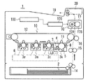
図1には本発明の一実施形態に係るヒータ制御部170を備えた画像形成装置1の構成の概要が、図2にはヒータ制御部170の構成が、それぞれ示されている。
FIG. 1 shows an outline of a configuration of an
画像形成装置1は、電子写真方式のプリンタエンジン10を備えたカラープリンタである。ハウジングの上部にタッチパネルディスプレイを有する操作パネル20が配置されている。なお、画像形成装置1は、プリンタと他の機器(ファクシミリ、ファイルサーバなど)とを集約したMFP(Multi-functional Peripheral :多機能機または複合機)であってもよい。
The
プリンタエンジン10は、4個のイメージングユニット3y,3m,3c,3k、プリントヘッド6、および中間転写ベルト12などを有する。
The
イメージングユニット3y〜3kは、それぞれ筒状の感光体4、帯電器5、現像器7、およびクリーナ8などを有している。イメージングユニット3y〜3kの基本的な構成は同様である。
Each of the
プリントヘッド6は、イメージングユニット3y〜3kのそれぞれに対してパターン露光を行うためのレーザビームLBを射出する。プリントヘッド6において、感光体4の回転軸方向にレーザビームLBを偏向する主走査が行われる。この主走査と並行して、感光体4を定速回転させる副走査が行われる。
The print head 6 emits a laser beam LB for performing pattern exposure on each of the
中間転写ベルト12は、トナー像の一次転写における被転写部材であり、一対のローラ間に巻回されて回転する。中間転写ベルト12の内側には、イメージングユニット3y,3m,3c,3kごとに一次転写ローラ11が配置されている。
The
カラー印刷モードにおいて、イメージングユニット3y〜3kは、Y(イエロー)、M(マゼンタ)、C(シアン)、およびK(ブラック)の4色のトナー像を並行して形成する。4色のトナー像は、回転中の中間転写ベルト12に順次に一次転写される。最初にYのトナー像が転写され、それに重なるようMのトナー像、Cのトナー像、およびKのトナー像が順次に転写される。
In the color printing mode, the
一次転写されたトナー像は、二次転写ローラ16と対向する印刷位置において、給紙トレイ14から取り出されてタイミングローラ15を経て搬送されてきた用紙(シート)2に二次転写される。二次転写の後、定着器17の内部を通過し、排出ローラ18により上部の排紙トレイ19へ送り出される。定着器17を通過するとき、加熱および加圧によってトナー像が用紙2に定着する。
The primary-transferred toner image is secondarily transferred to a sheet (sheet) 2 that has been taken out of the
定着器17は、加熱ローラ17Aと加圧ローラ17Bとを有し、これらのローラで用紙2を搬送しながら熱と圧力とを用紙2に加える。加熱ローラ17Aは、その筒状の芯金内に定着のための熱源としてハロゲンランプ(すなわちハロゲンヒータ)70を内蔵している。ハロゲンランプ70は、ヒータ制御部170から供給される電力により発熱し、加熱ローラ17Aの周面を昇温させる。用紙2が定着器17を通過するときに、加熱ローラ17Aが定着に適した温度になるように、ヒータ制御部170によりハロゲンランプ70が制御される。
The
図2に示すように、ヒータ制御部170は、ハロゲンランプ70を点灯させるための基本的な構成要素として、ハロゲンランプ70に電力を供給する駆動部171とそれを制御するPWM制御部172とを有する。
As shown in FIG. 2, the
駆動部171は、商用電源300から供給される交流電力を整流し、所定の電圧の電力に変換して出力するスイッチング電源回路である。
The
駆動部171は、整流用のダイオードブリッジ711、コンデンサ712,714とコイル713とからなるπ型ノイズフィルタ、スイッチング素子715とダイオード716とコイル717とからなる降圧チョッパ部、およびドライバ718を有する。スイッチング素子715は、例えばパワートランジスタである。IGBT(Insulated Gate Bipolar Transistor )またはMOS−FET(Metal-Oxide-Semiconductor Field-Effect Transistor )であってもよい。
The
コイル717とハロゲンランプ70とスイッチング素子715のコレクタ・エミッタ間とがこの順に直列に接続され、この直列回路がπ型ノイズフィルタの出力側のコンデンサ714に並列に接続される。コイル717とハロゲンランプ70との直列回路に対して並列になるようダイオード716のカソードがコイル717に接続されるとともにアノードがハロゲンランプ70に接続されている。ダイオード716は、スイッチング素子715が閉状態から開状態になったときに、コイル717に溜まっている磁気エネルギーを回生電流としてに流すための還流素子である。
The
ドライバ718は、PWM制御部172から入力されるPWM信号S1をスイッチング素子715の制御に適した電圧レベルの信号に変換してスイッチング素子715のベースに入力する。
The
駆動部171は、PWM信号S1のデューティ比に応じた電圧の電力をハロゲンランプ70に供給する。パルス幅変調により、正弦波に近い波形の電流がハロゲンランプ70に供給される。
The
PWM制御部172は、上位制御部である制御回路100から開始指令が入力されると、駆動部171の制御を開始する。その後、停止指令が入力されるまで駆動部171を制御する。制御回路100は、画像形成装置1の全体の制御を受け持つコントローラである。
When a start command is input from the
PWM制御部172には、加熱ローラ17Aの周面の温度を検出するセンサ75から温度検出信号S75が入力される。PWM制御部172は、ウォームアップモード、待機モード、および印刷モードにおいて、温度検出信号S75に基づいて加熱ローラ17Aの温度を検知し、加熱ローラ17Aの温度が予め設定された温度になるようにPWM信号S1を生成する。PWM信号S1の周波数は、例えば20kHzである。すなわち、この場合のデューティーサイクルは、50μsである。
A temperature detection signal S75 is input to the
さて、画像形成装置1は、ハロゲンランプ70の経時変化の進行を遅らせる機能を有している。以下、この機能を中心に画像形成装置1の構成および動作を説明する。
The
ヒータ制御部170による制御には、「ヒータ寿命延長モード」と「温度リップル抑制モード」とがある。ヒータ制御部170は、これらのモードを選択的に切り替え可能となっている。
The control by the
ヒータ寿命延長モードは、用紙2に画像を印刷することなく待機する待機モード時(待機期間)において、PWM制御におけるデューティー比を100%未満としかつ所定の期間ごとにデューティーサイクルよりも長いオフ期間を設けるよう制御するモードである。オフ期間では、PWM信号S1のディティー比を0%とすることにより、ハロゲンランプ70に対する電力の供給を停止する。
In the heater life extension mode, in a standby mode (standby period) in which the image forming apparatus waits without printing an image on the
ヒータ寿命延長モードによると、ハロゲンランプ70のフィラメントが局部的に細くなる経時変化の進行を遅らせてハロゲンランプ70の寿命を延ばすことができる。ただし、PWM制御を行ったり行わなかったりしてハロゲンランプ70の点灯を断続させるので、点灯を断続させない場合と比べて、加熱ローラ71Aの温度の変動が顕著になる。
According to the heater life extension mode, it is possible to extend the life of the
温度リップル抑制モードは、待機モード時においてオフ期間を設けないモード、すなわち待機モードである期間にわたってPWM制御を継続するモードである。加熱ローラ71Aの温度の変動は小さいが、フィラメントが局部的に細くなる経時変化の進行を遅らせることはできない。 The temperature ripple suppression mode is a mode in which an off period is not provided in the standby mode, that is, a mode in which the PWM control is continued over a period of the standby mode. Although the temperature fluctuation of the heating roller 71A is small, the progress of the temporal change in which the filament becomes thin locally cannot be delayed.
再び図2を参照して、ヒータ制御部170は、ヒータ寿命延長モードに関わる構成要素として、不揮発性のメモリ173と寿命延長制御ブロック174とを有する。
Referring to FIG. 2 again,
メモリ174は、ハロゲンランプ70の総点灯時間Tonおよび設定テーブルD70などを記憶する。
The
総点灯時間Tonは、PWM制御部172によりPWM制御が行われた時間の積算値であり、ハロゲンランプ70の余命(残寿命)の判定の目安としてPWM制御部172により積算されて適時にメモリ173に書き込まれる。
The total lighting time Ton is an integrated value of the time during which the PWM control is performed by the
設定テーブルD70は、待機期間のうちのオフ期間以外であるオン期間におけるデューティー比の選択肢ごとに、待機期間においてPWM制御部172が行うべき制御を定めた指令情報Cpwmを対応づけた制御情報である。後に詳細を述べる。
The setting table D70 is control information in which command information Cpwm defining control to be performed by the
寿命延長制御ブロック174は、判断部741、受付部742、表示部743、および指令部744などを有する。寿命延長制御ブロック174の機能は、プロセッサを含むヒータ制御部170のハードウェア構成により、および制御プログラムがプロセッサによって実行されることにより実現される。
The life
判断部741は、ヒータ寿命延長モードと温度リップル抑制モードとの切り替えの選択を、ハロゲンランプ70の余命(残寿命)Lrに基づいて判断する。
The
すなわち、予め定められたハロゲンランプ70の耐久点灯時間(寿命)とメモリ173から読み出した総点灯時間Tonとの差を余命Lrとして算出する。または、制御回路100から印刷に使用された用紙2の枚数の積算値である総通紙枚数Dpnを取得して総点灯時間Tonに換算し、同様に余命Lrを算出する。そして、算出した余命Lrがしきい値未満である場合に、ヒータ寿命延長モードを選択すると判断する。
That is, the difference between the predetermined durable lighting time (lifetime) of the
ただし、サービスパーソンまたはユーザ(管理者を含む)が行う動作設定操作によりヒータ寿命延長モードが指定されている場合には、余命Lrの長さにかかわらず、ヒータ寿命延長モードを選択すると判断する。 However, if the heater life extension mode is designated by an operation setting operation performed by a service person or a user (including an administrator), it is determined that the heater life extension mode is selected regardless of the length of the remaining life Lr.
受付部742は、ヒータ寿命延長モードと温度リップル抑制モードとの切り替えの選択を、サービスパーソンまたはユーザの操作に基づいて行うための入力処理を行う。操作パネル20を用いてヒータ寿命延長モードまたは温度リップル抑制モードが指定されると、受付部742は、指定されたモードを判断部741に通知する。このとき、判断部741は、通知されたモードを例えばメモリ173に記憶させておく。
The
表示部743は、判断部741がヒータ寿命延長モードまたは温度リップル抑制モードの選択を判断する際に算出した余命Lrを操作パネル20のタッチパネルディスプレイにより表示する処理を行う。この表示は、余命Lrがしきい値未満である場合にのみ行ってもよいし、余命Lrの長さにかかわらず、印刷ジョブを実行するときまたはユーザが状態確認操作を行ったときに行ってもよい。
The
ユーザは、表示された余命Lrに基づいて、ヒータ寿命延長モードの制御の要否を判断することができる。 The user can determine whether the control of the heater life extension mode is necessary based on the displayed life expectancy Lr.
そして、例えば余命Lrが予想外に短いと感じてハロゲンランプ70の寿命が尽きる時期を遅らせたいと思ったときなどに、温度リップル抑制モードからヒータ寿命延長モードに指定を変更することができる。
The designation can be changed from the temperature ripple suppression mode to the heater life extension mode, for example, when the life expectancy Lr is unexpectedly short and it is desired to delay the life of the
また、既にヒータ寿命延長モードを指定している場合であっても、設定テーブルD70における選択肢のうち、延命に有利なものを選択するよう、サービスパーソンに設定変更を依頼することができる。 Further, even when the heater life extension mode is already specified, the service person can be requested to change the setting so as to select an option that is advantageous for extending the life among the options in the setting table D70.
指令部744は、PWM制御部172に対して待機期間におけるPWM信号S1の生成のオンオフを指令する。すなわち、PWM制御部172から待機期間への移行が通知されると、指令部744は、設定テーブルD70から指令情報Cpwmを抽出してPWM制御部172に与える。
The
指令情報Cpwmは、待機期間におけるオン期間とオフ期間との配置パターン、オン期間およびオフ期間のそれぞれの長さ、およびオン期間のデューティー比Xを指定する情報である。なお、温度リップル抑制モードでは待機期間の全体がオン期間であるので、温度リップル抑制モードが選択されている場合に与えられる指令情報Cpwmは、デューティー比Xのみを指定するものでよい。 The command information Cpwm is information that specifies the arrangement pattern of the ON period and the OFF period in the standby period, the respective lengths of the ON period and the OFF period, and the duty ratio X of the ON period. Since the entire standby period is the ON period in the temperature ripple suppression mode, the command information Cpwm given when the temperature ripple suppression mode is selected may specify only the duty ratio X.
PWM制御部172は、画像形成装置1に印刷ジョブが入力されて制御回路100から印刷モードへの移行が指令されるまで、与えられた指令情報Cpwmに従ってオン期間においてPWM制御を行い、オフ期間においてPWM制御を停止する。
The
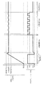
図3には加熱ローラ17Aの温度制御の概要が示されている。図3では、待機期間Pwaのモードが温度リップル抑制モードとされている。
FIG. 3 shows an outline of the temperature control of the
画像形成装置1は、電源スイッチがオンとされたとき、または節電モード(スリープモード)から通常モードに復帰するときに、加熱ローラ17Aを定着に適した温度に昇温させるウォームアップを行う。
When the power switch is turned on, or when the
ウォームアップ期間Pwuにおいては、例えば常温から恒温制御の目標温度Tsまで最短時間で昇温させるために、デューティー比Xを最大値の100%とする。そして、目標温度Tsを超える頃にデューティー比Xを0%に切り替え、すなわちハロゲンランプ70への電力の供給を停止し、加熱ローラ17Aの温度を目標温度Tsに落ち着かせる。
In the warm-up period Pwu, the duty ratio X is set to 100% of the maximum value, for example, in order to raise the temperature from the normal temperature to the target temperature Ts of the constant temperature control in the shortest time. When the temperature exceeds the target temperature Ts, the duty ratio X is switched to 0%, that is, the supply of power to the
加熱ローラ17Aの温度が目標温度Tsに落ち着くと、ウォームアップ期間Pwuが終わって待機期間Pwaが始まる。ただし、印刷ジョブが実行待ちである場合には、ウォームアップが終わると、待機期間Pwaを経ることなく印刷期間Pprになる。
When the temperature of the
待機期間Pwaにおいては、温度リップル抑制モードが選択された場合には、デューティー比Xを、一定の値(例えば20%)とする。この値は、ハロゲンランプ70による加熱量と加熱ローラ17Aから周囲への放熱量とが均衡して加熱ローラ17Aが目標温度Tsに保たれるよう設定されたものである。
In the standby period Pwa, when the temperature ripple suppression mode is selected, the duty ratio X is set to a constant value (for example, 20%). This value is set so that the amount of heating by the
印刷ジョブの入力を契機として、画像形成装置1は、待機モードから印刷モードに移行する。
Upon input of a print job, the
印刷モードへの移行により始まる印刷期間Pprにおいては、用紙2が定着器17を通過することによる放熱量を補って加熱ローラ17Aを目標温度Tsに保つようデューティー比Xを適時に切り替える。図3では、100%と70%との二者択一の切替えを周期的に行う例が示されている。ただし、多段階の切替えを行うことも可能である。
In the printing period Ppr that starts when the mode shifts to the printing mode, the duty ratio X is switched in a timely manner so as to compensate for the amount of heat released by the
印刷期間Pprでは、用紙2の通過による放熱条件の変化に伴って、加熱ローラ17Aの温度が変動する。すなわち、待機期間Pwaと比べて顕著なリップルが生じる。
In the printing period Ppr, the temperature of the
印刷が終わると、待機モードに移行する。印刷期間Pprに続く待機期間Pwaにおいても、ウォームアップ期間Pwaに続く待機期間Pwaと同様の温度制御を行う。 When printing is completed, the mode shifts to the standby mode. In the standby period Pwa following the printing period Ppr, the same temperature control as in the standby period Pwa following the warm-up period Pwa is performed.
次に、ヒータ寿命延長モードが選択された場合における待機期間Pwaの温度制御を説明する。説明において、待機期間Pwaは印刷期間Pprに続く期間であるものとする。 Next, temperature control during the standby period Pwa when the heater life extension mode is selected will be described. In the description, it is assumed that the waiting period Pwa is a period following the printing period Ppr.
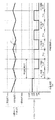
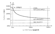
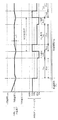
図4にはヒータ寿命延長モードにおける加熱ローラ17Aの温度制御の第1例が、図5にはオフ期間Poffにおけるフィラメント702の温度変化の例が、それぞれ示されている。また、図6には待機期間Pwaにおけるハロゲンランプ70の内部の状態が模式的に示されている。
FIG. 4 shows a first example of temperature control of the
図4において、待機期間Pwaは、単位時間UTごとに設けられるオフ期間Poffとオフ期間Poff以外であるオン期間Ponとから構成される。単位時間UTは、1秒〜数秒程度の時間とされる。 In FIG. 4, the waiting period Pwa includes an off period Poff provided for each unit time UT and an on period Pon other than the off period Poff. The unit time UT is a time of about one second to several seconds.
待機期間Pwaの全体の長さは、次の印刷ジョブの入力がいつであるかに依存し、数秒以内の場合もあるし、数分以上の場合もある。一定時間(例えば3〜5分)にわたって印刷ジョブの入力が無いときに節電モードに移行する機能が画像形成装置1に設けられている場合は、その一定時間の値が待機期間Pwaの最大長さとなる。
The total length of the waiting period Pwa depends on when the next print job is input, and may be within a few seconds or may be several minutes or more. If the
つまり、待機期間Pwaが単位時間UTよりも長い場合に1個以上のオフ期間Poffが設けられる。 That is, when the waiting period Pwa is longer than the unit time UT, one or more off periods Poff are provided.
図4の第1例では、待機期間Pwaの開始直後はオン期間Ponとし、単位時間UTよりも短い設定時間が経過したときにオフ期間Poffに切り替え、単位時間UTが経過したときにオン期間Ponに戻す。以降は、同様の要領でオン期間Ponへの切替えとオン期間Ponの切替えとを繰り返す。 In the first example of FIG. 4, the on-period Pon is set immediately after the start of the standby period Pwa, and is switched to the off-period Poff when a set time shorter than the unit time UT elapses, and is turned on when the unit time UT elapses. Return to Thereafter, switching to the ON period Pon and switching of the ON period Pon are repeated in a similar manner.
オン期間Ponのデューティー比Xは、例えば50%とされる。直前の印刷期間Pprでは上に述べた通り100%と70%との切替えを行うので、この50%というデューティー比Xは、直前の印刷期間Pprでのデューティー比Xよりも低い。 The duty ratio X of the ON period Pon is, for example, 50%. Since switching between 100% and 70% is performed in the immediately preceding printing period Ppr as described above, the duty ratio X of 50% is lower than the duty ratio X in the immediately preceding printing period Ppr.
単位時間UTに対するオン期間Ponの割合であるヒータ点灯率Rは、例えば50%とされる。すなわち、単位時間UTを例えば1000msとする場合に、オン期間Ponの長さは、500msとされる。必然的にオフ期間Poffの長さも500msとされる。 The heater lighting rate R, which is a ratio of the ON period Pon to the unit time UT, is, for example, 50%. That is, when the unit time UT is set to, for example, 1000 ms, the length of the ON period Pon is set to 500 ms. Inevitably, the length of the off period Poff is also set to 500 ms.
オフ期間Poffは、上にに述べた通りPWM制御のデューティーサイクルよりも長い所定の時間にわたってハロゲンランプ70に対する電力の供給を停止する期間である。このようなオフ期間Poffを設けることにより、次の通りハロゲンランプ70の寿命を延ばすことができる。
The off period Poff is a period during which the supply of power to the
図5に示すように、電力の供給を停止するヒータオフの以前において、点灯中のハロゲンランプ70のフィラメントは、その材料であるタングステンの蒸発が活発な高温状態である。図示の例では、ヒータオフの直前におけるフィラメントの温度(初期温度)は、2500K(2226.85℃)である。
As shown in FIG. 5, before the heater is turned off to stop supplying power, the filament of the
ヒータオフにより、フィラメントの温度は降下する。はじめは急激に降下し、次第に降下は緩やかなる。初期温度からタングステンの蒸発が実質的に止まるとされる2100K程度まで降下する時間tdは、5〜20ms程度である。 By turning off the heater, the temperature of the filament decreases. It descends sharply at first and gradually descends. The time td from the initial temperature to about 2100 K at which the evaporation of tungsten is substantially stopped is about 5 to 20 ms.
この時間tdは、PWM制御のデューティーサイクル(50μs)と比べると桁違いに長いが、単位時間UT(1〜数秒)と比べると、桁違いに短い。 The time td is significantly longer than the duty cycle of the PWM control (50 μs), but is significantly shorter than the unit time UT (1 to several seconds).
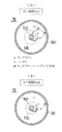
図6(A)に示すように、オン期間Ponにおいては、電力の供給が停止することはなく、仮にあったとしてもその時間はデューティーサイクル未満と短いので、フィラメント702は高温に保たれ、ハロゲンランプ70の内部でハロゲンサイクルが進行する。
As shown in FIG. 6A, in the on-period Pon, power supply does not stop, and even if there is, the time is short, which is less than the duty cycle. The halogen cycle proceeds inside the
すなわち、フィラメント702から蒸発したタングステンがハロゲン(例えば臭素)と反応し、タングステン−ハロゲン化合物が生成される。この化合物は、管壁701が250℃以上であれば、管壁701に付着することなく浮遊する。化合物は、熱対流によってフィラメント702に近いゾーン705に運ばれて1400℃以上に昇温すると、タングステンとハロゲンとに分解される。自由になったハロゲンは浮遊する。他方、タングステンはフィラメント702に戻って沈澱する。
That is, tungsten evaporated from the
しかし、フィラメント702に均等に戻るのではなく、蒸発の激しい高温部分には戻りにくく、比較的に温度の低い部分に戻りやすい。このため、ハロゲンサイクルが繰り返されるにつれてフィラメント702の高温部分がやせ細り、ついには断線してハロゲンランプ70の寿命が尽きる。
However, instead of returning to the
これに対して、図6(B)に示すように、オフ期間Poffにおいては、フィラメント702の温度が降下してタングステンの蒸発が止まり、化合物の生成は不活発となる。既に存在する化合物は、管壁701が250℃以上である間は管壁701に付着することなく浮遊する。
On the other hand, as shown in FIG. 6B, in the off-period Poff, the temperature of the
また、1400℃以上のゾーン705が存在する間は化合物の分解は起こり、ハロゲンから分離したタングステンは、フィラメント702に戻る。このとき、フィラメント702からのタングステンの蒸発が止まっているので、タングステンの沈殿はオン期間Ponと比べて均等になる。
While the
つまり、オフ期間Poffを設けることにより、タングステンの蒸発によるフィラメント702の細りが止まるとともに、オン期間Ponにおけるフィラメント702の局部的なやせ細りを多少なりとも回復させる効果が得られる。
That is, by providing the off-period Poff, the thinning of the
タングステンの蒸発が止まることでタングステンの粉が管壁701に付着する黒化が起こりにくいので、オフ期間Poffの長さを管壁701の温度が250℃以下に降下する時間以上としても、ハロゲンランプ70の寿命が黒化により短くなることはない。
Since the blackening of the tungsten powder that adheres to the
ただし、オフ期間Poffを長くし過ぎると、すなわちヒータ点灯率Rを小さくし過ぎると、加熱ローラ17Aの温度Tが大きく降下して目標温度Tsとの乖離が許容範囲を超えてしまう。
However, if the off-period Poff is too long, that is, if the heater lighting rate R is too small, the temperature T of the
したがって、ハロゲンランプ70の寿命を延ばすには、加熱ローラ17Aの温度Tの変動が許容される範囲内でオフ期間Poffをできるだけ長くするのが好ましい。
Therefore, in order to extend the life of the
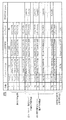
図7には設定テーブルD70の例が、図8にはヒータ寿命延長モードにおけるリップル中心温度Tcの設定の例が、図9には設定テーブルD70におけるデューティー比Xとヒータ点灯率Yとの関係が、それぞれ示されている。 7 shows an example of the setting table D70, FIG. 8 shows an example of the setting of the ripple center temperature Tc in the heater life extension mode, and FIG. 9 shows the relationship between the duty ratio X and the heater lighting rate Y in the setting table D70. , Respectively.
図7に示す設定テーブルD70においては、20%から99.9%までのデューティー比Xの範囲が0からNまでの(N+1)段階に区分され、段階ごとにヒータ点灯率Yが定められ、同じく段階ごとに待機期間PwaにおけるリップルdTが想定されている。 In the setting table D70 shown in FIG. 7, the range of the duty ratio X from 20% to 99.9% is divided into (N + 1) stages from 0 to N, and the heater lighting rate Y is determined for each stage. A ripple dT in the standby period Pwa is assumed for each stage.
段階0は、温度リップル抑制モードに対応する。温度リップル抑制モードでは、オフ期間Poffを設けないので、段階0のヒータ点灯率Yは100%であり、リップルdTは±0%(中心温度に対する上昇分および降下分が共に0%)とされている。
段階1〜段階Nは、ヒータ寿命延長モードに対応する。ただし、段階1〜段階Nのうちの一部である段階A1〜段階Bnが、実際の制御に適用する選択肢とされている。段階1〜段階nは、オフ期間Poffが短すぎてフィラメント702が十分に冷えないか、十分に冷えて寿命延長の効果が得られたとしてもほんの僅かであることから、選択肢から除外されている。また、段階C1〜段階Nは、リップルdTが大きくなり過ぎて加熱ローラ17Aが過剰に昇温するおそれがあることから、選択肢から除外されている。
ところで、本実施形態においては、ヒータ寿命延長モードに2つのサブモードが設けられている。その1つは、温度リップル抑制モードと比べてリップルdTが大きくなることによる消費電力の増加を抑える「省エネルギー優先モード」である。 By the way, in this embodiment, two sub-modes are provided in the heater life extension mode. One of them is an “energy saving priority mode” that suppresses an increase in power consumption due to an increase in the ripple dT as compared with the temperature ripple suppression mode.
他の1つは、印刷モードに移行した後に定着を良好とするために加熱ローラ17Aが目標温度Ts以上になるのを待たなければならない状況の発生を抑える「待ち時間優先モード」である。
The other is a “waiting time priority mode” that suppresses the occurrence of a situation in which it is necessary to wait for the
図8(A)に示すように、省エネルギー優先モードにおいては、リップル中心温度Tcを目標温度Tsに設定する(Tc=Ts)。この場合は、加熱ローラ17Aの温度Tが目標温度Tsよりも低いときに印刷モードに切り替わると、待ち時間が生じて印刷の開始が遅れる。
As shown in FIG. 8A, in the energy saving priority mode, the ripple center temperature Tc is set to the target temperature Ts (Tc = Ts). In this case, if the mode is switched to the print mode when the temperature T of the
しかし、加熱ローラ17Aの温度Tが目標温度Tsよりも高いときには消費電力が増えるが、目標温度Tsよりも低いときには消費電力が減るので、待機期間Pwaの全体の消費電力は、温度Tが目標温度Tsで一定である恒温状態とほぼ等しい。
However, when the temperature T of the
これに対して、図8(B)に示すように、待ち時間優先モードにおいては、リップル中心温度Tcを目標温度Tsよりもリップルdtの半分だけ高い温度に設定する(Tc=Ts+dt/2)。この場合は、加熱ローラ17Aの温度Tが常に目標温度Tsよりも高いので、温度Tが目標温度Tsで一定である場合と比べて消費電力が大きくなる。しかし、待ち時間は生じないので、印刷の遅れはない。ジョブの入力から1枚目の印刷物の出力までの時間であるFPOT(First Print Output Time) を短縮する上で、待ち時間優先モードは、省エネルギー優先モードと比べて有利である。
On the other hand, as shown in FIG. 8B, in the waiting time priority mode, the ripple center temperature Tc is set to a temperature higher than the target temperature Ts by half the ripple dt (Tc = Ts + dt / 2). In this case, since the temperature T of the
図9に示すように、省エネルギー優先モードおよび待ち時間優先モードのいずれであっても、デューティー比Xを大きくするほど、ヒータ点灯率Yを小さくする必要がある。そして、図示は省略したが、ヒータ点灯率Yを小さくするほど、すなわちオフ期間Poffを長くするほど、リップルdtは大きくなる。 As shown in FIG. 9, in both the energy saving mode and the waiting time mode, it is necessary to decrease the heater lighting rate Y as the duty ratio X increases. And although illustration is omitted, ripple dt becomes large, so that heater lighting rate Y is made small, ie, off period Poff is made long.
省エネルギー優先モードでは、リップルdtの大きさが待ち時間の最大値(最大待ち時間)に対応する。つまり、オフ期間Poffを長くするほど、最大待ち時間が長くなるおそれがある。ハロゲンランプ70の寿命を延ばす上ではオフ期間Poffを長くするのが好ましいが、そうした場合には待ち時間が長くなるかもしれない。このトレードオフを踏まえてオフ期間Poffの長さを変更できるよう、設定テーブルD70において段階A1〜Bnの選択肢が定められ、これらの選択肢のそれぞれに当該モードに適用する指令情報Cpwmが対応づけられている。
In the energy saving priority mode, the magnitude of the ripple dt corresponds to the maximum value of the waiting time (maximum waiting time). That is, the longer the off period Poff, the longer the maximum waiting time may be. To extend the life of the
また、待ち時間優先モードでは、リップルdtの大きさが消費電力増加量に対応する。つまり、オフ期間Poffを長くするほど、消費電力が増加する。ハロゲンランプ70の寿命を延ばす上ではオフ期間Poffを長くするのが好ましいが、そうすることにより消費電力が増えてしまう。このトレードオフを踏まえてオフ期間Poffの長さを変更できるよう、設定テーブルD70において段階A1〜Bjの選択肢が定められ、これらの選択肢のそれぞれに当該モードに適用する指令情報Cpwmが対応づけられている。
In the waiting time priority mode, the magnitude of the ripple dt corresponds to the increase in power consumption. That is, the power consumption increases as the off-period Poff increases. In order to extend the life of the
なお、待ち時間優先モードでは、図8に示す通り、リップル中心温度Tcが省エネルギー優先モードの場合と比べて高いことから、加熱ローラ17Aの温度Tが許容範囲の上限温度Tmaxを超えやすい。したがって、待ち時間優先モードの選択可能範囲(A1〜Bj)は、省エネルギー優先モードの選択可能範囲(A1〜Bn)よりも狭い。
In the waiting time priority mode, as shown in FIG. 8, since the ripple center temperature Tc is higher than in the energy saving priority mode, the temperature T of the
図10にはヒータ寿命延長モードにおける加熱ローラ17Aの温度制御の第2例が、図11には同じく第3例がそれぞれ示されている。
FIG. 10 shows a second example of temperature control of the
図10の第2例は、待機期間Pwaにおけるオン期間Ponとして、低デューティー比期間Plowと高デューティー比期間Phighとを設けるものである。 In the second example of FIG. 10, a low duty ratio period Plow and a high duty ratio period Phigh are provided as the ON period Pon in the standby period Pwa.
低デューティー比期間Plowは、そのデューティー比Xとして、温度リップル抑制モードにおけるデューティー比X(恒温制御での目標温度Tsに対応するデューティー比X)が設定された期間である。低デューティー比期間Plowのデューティー比Xは、例えば20%である。 The low duty ratio period Plow is a period in which the duty ratio X in the temperature ripple suppression mode (the duty ratio X corresponding to the target temperature Ts in the constant temperature control) is set as the duty ratio X. The duty ratio X in the low duty ratio period Plow is, for example, 20%.
高デューティー比期間Phighは、そのデューティー比Xとして、低デューティー比期間Plowのデューティー比Xよりも高いデューティー比Xが設定された期間である。高デューティー比期間Phighのデューティー比Xは、例えば70%である。 The high duty ratio period Phigh is a period in which a duty ratio X higher than the duty ratio X of the low duty ratio period Plow is set as the duty ratio X. The duty ratio X in the high duty ratio period Phigh is, for example, 70%.
この第2例では、待機期間Pwaの開始直後は低デューティー比期間Plowとし、単位時間UTよりも短い第1の設定時間が経過したときに高デューティー比期間Phighに切り替える。さらに、単位時間UTよりも短くかつ第1の設定時間よりも長い第2の設定時間が経過したときに、オフ期間Poffに切り替え、単位時間UTが経過したときに低デューティー比期間Plowに戻す。以降は、同様の要領で高デューティー比期間Phighへの切替え、オフ期間Poffへの切替え、および低デューティー比期間Plowに戻す切替えを繰り返す。 In the second example, immediately after the start of the standby period Pwa, the low duty ratio period Plow is set, and when the first set time shorter than the unit time UT elapses, the period is switched to the high duty ratio period Phigh. Further, when the second set time shorter than the unit time UT and longer than the first set time elapses, the operation is switched to the off period Poff, and when the unit time UT elapses, the operation is returned to the low duty ratio period Plow. Thereafter, switching to the high duty ratio period Phigh, switching to the off period Poff, and switching back to the low duty ratio period Plow are repeated in the same manner.
第1の設定時間、すなわち低デューティー比期間Plowの長さは、単位時間UTを例えば2秒とした場合に、例えば1秒とされる。第2の設定時間と第1の設定時間との差、すなわち高デューティー比期間Phighの長さは、例えば、0.5秒とされる。この場合のオフ期間Poffの長さは、0.5秒であり、ヒータ点灯率Yは、75%である。 The first set time, that is, the length of the low duty ratio period Plow is, for example, 1 second when the unit time UT is, for example, 2 seconds. The difference between the second set time and the first set time, that is, the length of the high duty ratio period Phigh is, for example, 0.5 second. In this case, the length of the off period Poff is 0.5 seconds, and the heater lighting rate Y is 75%.
図11の第3例も、待機期間Pwaにおけるオン期間Ponとして、低デューティー比期間Plowと高デューティー比期間Phighとを設けるものである。 The third example of FIG. 11 also includes a low duty ratio period Plow and a high duty ratio period Phigh as the ON period Pon in the standby period Pwa.
この第3例では、待機期間Pwaの開始直後は低デューティー比期間Plowとし、第1の設定時間が経過したときにオフ期間Poffに切り替え、第2の設定時間が経過したときに、高デューティー比期間Phighに切り替える。つまり、高デューティー比期間Phighをオフ期間Poffの直後に設ける。そして、単位時間UTが経過したときに低デューティー比期間Plowに戻す。以降は、同様の要領でオフ期間Poffへの切替え、高デューティー比期間Phighへの切替え、および低デューティー比期間Plowに戻す切替えを繰り返す。 In the third example, immediately after the start of the standby period Pwa, the low duty ratio period Plow is set, and when the first set time elapses, the off period Poff is switched. When the second set time elapses, the high duty ratio Poff is set. Switch to period Phigh. That is, the high duty ratio period Phigh is provided immediately after the off period Poff. Then, when the unit time UT has elapsed, the period is returned to the low duty ratio period Plow. Thereafter, switching to the off period Poff, switching to the high duty ratio period Phigh, and switching back to the low duty ratio period Plow are repeated in the same manner.
低デューティー比期間Plow、オフ期間Poff、および高デューティー比期間Phighのそれぞれの長さは、第2例と同じでもよいし、異なってもよい。 The lengths of the low duty ratio period Plow, the off period Poff, and the high duty ratio period Phigh may be the same as or different from the second example.
図12にはヒータ制御部170における処理の流れが示されている。
FIG. 12 shows a flow of processing in the
ハロゲンランプ70の制御の開始に際して、設定されているモードを確認する(#501)。
At the start of the control of the
温度リップル抑制モードが設定されている場合は、直ちにステップ#504へ進み、ステップ#504において印刷期間への移行を指令する印刷コマンドの有無を確認する。
If the temperature ripple suppression mode is set, the process immediately proceeds to step # 504, and in
ヒータ寿命延長モードのうちの省エネルギー優先モードが設定されている場合は、Tc=Tsとして作成された制御条件を示す指令情報Cpwmを制御に適用するべき情報として選択し、設定テーブルD70から取得する。その後にステップ#504へ進む。 When the energy saving priority mode of the heater life extension mode is set, the command information Cpwm indicating the control condition created as Tc = Ts is selected as the information to be applied to the control, and is acquired from the setting table D70. Thereafter, the process proceeds to step # 504.
ヒータ寿命延長モードのうちの待ち時間優先が設定されている場合は、Tc=Ts+dT/2として作成された制御条件を示す指令情報Cpwmを制御に適用するべき情報として選択し、設定テーブルD70から取得する。リップル中心温度Tcを目標温度Tsとして作成された制御条件を示す指令情報Cpwmを制御に適用するべき情報として選択し、設定テーブルD70から取得する。その後にステップ#504へ進む。 When the waiting time priority is set in the heater life extension mode, the command information Cpwm indicating the control condition created as Tc = Ts + dT / 2 is selected as the information to be applied to the control and acquired from the setting table D70. I do. The command information Cpwm indicating the control condition created using the ripple center temperature Tc as the target temperature Ts is selected as information to be applied to the control, and is obtained from the setting table D70. Thereafter, the process proceeds to step # 504.
印刷コマンドがない場合は(#504でNO) 、ステップ#509へ進む。印刷コマンドがある場合は、加熱ローラ17Aを目標温度Tsに昇温させ(#505)、印刷期間Pprのための制御(PWM制御)を開始する(#506)。
If there is no print command (NO in # 504), the process proceeds to step # 509. If there is a print command, the
印刷中に、総点灯時間Tonに基づいて、または総点灯時間Tonと総通紙枚数Dpnとに基づいて、ハロゲンランプ70が予め定められた寿命に達したか否かを判断する(#507)。
During printing, it is determined whether or not the
寿命に達したと判断した場合は(#507でYES) 、ハロゲンランプ70の交換を要求するメーッセージおよびサービスコードを操作パネル20に表示させる(#514)。
If it is determined that the life has expired (YES in # 507), a message requesting replacement of the
寿命に達していないと判断した場合は(#507でNO) 、印刷の完了を確認した後に(#508でYES) 、待機期間Pwaのための制御を開始する(#509)。 If it is determined that the life has not expired (NO in # 507), after completion of printing is confirmed (YES in # 508), control for the standby period Pwa is started (# 509).
なお、ウォームアップが完了する以前の段階でステップ#504からステップ#509へ進んだ場合は、ステップ#504においてウォームアップを終えてから待機期間Pwaのための制御を開始する。
If the process proceeds from step # 504 to step # 509 before the completion of the warm-up, control for the standby period Pwa is started after the warm-up is completed in
待機中においても、ハロゲンランプ70が寿命に達したか否かを判断する(#510)。
Even during the standby, it is determined whether or not the life of the
寿命に達したと判断した場合は(#510でYES) 、ステップ#514へ進んで上述の処理を行う。 If it is determined that the life has been reached (YES in # 510), the process proceeds to step # 514 to perform the above-described processing.
寿命に達していないと判断した場合は(#510でNO) 、ハロゲンランプ70の余命Lrを算出する(#511)。算出した余命Lrを操作パネル20に表示させてもよい。
If it is determined that the life has not been reached (NO in # 510), the remaining life Lr of the
続いて、算出した余命Lrに基づいて、ハロゲンランプ70が寿命に達する時期を遅らせる必要があるか否かを判断する(#512)。例えば余命Lrがしきい値未満である場合に遅らせる必要があると判断し、しきい値以上である場合に必要はないと判断する。
Subsequently, based on the calculated life expectancy Lr, it is determined whether or not it is necessary to delay the time when the life of the
遅らせる必要があると判断した場合は(#512でYES) 、温度リップル抑制モードをヒータ寿命延長モードに変更して(#513)、ステップ#501へ戻る。既にヒータ寿命延長モードが設定されている場合は、設定テーブルD70における指令情報Cpwmの選択について、ヒータ点灯率Yが現在よりも大きい段階のものを選択するように指定しておく。 If it is determined that it is necessary to delay (YES in # 512), the temperature ripple suppression mode is changed to the heater life extension mode (# 513), and the process returns to step # 501. If the heater life extension mode has already been set, the selection of the command information Cpwm in the setting table D70 is designated so that the heater information at the stage where the heater lighting rate Y is higher than the current level is selected.
寿命に達する時期を遅らせる必要がないと判断した場合は(#512でNO) 、ステップ#504へ戻る。 If it is determined that it is not necessary to delay the end of the life (NO in # 512), the process returns to step # 504.
以上の実施形態によると、待機期間Pwaにオフ期間Poffを設けてフィラメント702の細りを低減するので、画像を定着させるためのヒータとして用いるハロゲンランプ70の寿命を延ばすことができる。
According to the above-described embodiment, since the off-period Poff is provided in the standby period Pwa to reduce the thinning of the
上に述べた実施形態において、定着器17に設けるセンサ75は、ハロゲンランプ70の管壁701の温度を検出するものでもよい。その場合は、管壁701の温度と加熱ローラ17Aの周面の温度との対応関係を示す情報を記憶しておき、この情報に基づいて加熱ローラ17Aの温度を目標温度Tsに保つ制御を行えばよい。
In the embodiment described above, the
その他、画像形成装置1およびモータ制御部170それぞれの全体または各部の構成、動作および処理の内容、順序、またはタイミング、単位時間UTの長さ、ヒータ点灯率Y、オン期間Ponのデューティー比Xなどは、本発明の趣旨に沿って適宜変更することができる。
In addition, the configuration of the entire or each part of the
1 画像形成装置
2 用紙
17 定着器(定着部)
70 ハロゲンランプ(ハロゲンヒータ)
170 ヒータ制御部
173 メモリ
741 判断部
742 受付部
743 表示部
Dpn 総通紙枚数
Lr 余命(残寿命)
Poff オフ期間
Phigh 高デューティー比期間
Ppr 印刷期間(印刷モード時)
Pwa 待機期間(待機モード時)
Ton 総点灯時間
Ts 目標温度
X デューティー比
1
70 Halogen lamp (halogen heater)
170
Poff OFF period Phigh High duty ratio period Ppr Printing period (in printing mode)
Pwa Standby period (during standby mode)
Ton Total lighting time Ts Target temperature X Duty ratio
Claims (11)
PWM制御を行って前記ハロゲンヒータに電力を供給するヒータ制御部と、
を備え、
前記ヒータ制御部は、前記用紙に画像を印刷することなく待機する待機モード時において、PWM制御におけるデューティー比を100%未満としかつ所定の期間ごとに電力の供給を停止するオフ期間を設けるよう制御する、
ことを特徴とする画像形成装置。 A fixing unit including a halogen heater that performs heating for fixing a toner image formed on paper;
A heater control unit that performs PWM control to supply power to the halogen heater;
With
The heater control unit controls the duty ratio in the PWM control to be less than 100% and provides an OFF period in which power supply is stopped every predetermined period in a standby mode in which the image forming apparatus does not print an image on the sheet. Do
An image forming apparatus comprising:
請求項1記載の画像形成装置。 The heater control unit, the duty ratio in the standby mode, lower than the duty ratio in the print mode immediately before switching in the standby mode,
The image forming apparatus according to claim 1.
請求項1または2記載の画像形成装置。 The heater control unit controls the standby mode to provide a high duty ratio period set to a duty ratio higher than a duty ratio corresponding to a target temperature of the fixing unit in the standby mode.
The image forming apparatus according to claim 1.
請求項3記載の画像形成装置。 The heater control unit controls the high duty ratio period to be provided immediately after the off period,
The image forming apparatus according to claim 3.
請求項1ないし4のいずれかに記載の画像形成装置。 The heater control unit selectively switches between a heater life extension mode that extends the life of the halogen heater by providing the off period and a temperature ripple suppression mode that suppresses temperature ripple by not providing the off period. It is possible,
The image forming apparatus according to claim 1.
前記ヒータ寿命延長モードと前記温度リップル抑制モードとの切り替えの選択を、前記ハロゲンヒータの残寿命に基づいて判断する判断部を有する、
請求項5記載の画像形成装置。 The heater control unit includes:
A determination unit that determines selection of switching between the heater life extension mode and the temperature ripple suppression mode based on the remaining life of the halogen heater,
The image forming apparatus according to claim 5.
前記メモリに記憶された前記ハロゲンヒータの点灯時間に基づいて前記残寿命を決定する、
請求項6記載の画像形成装置。 A memory for storing a total lighting time of the halogen heater,
Determining the remaining life based on the lighting time of the halogen heater stored in the memory,
The image forming apparatus according to claim 6.
請求項6記載の画像形成装置。 The remaining life is determined based on the total number of sheets of the paper that have been fixed using the halogen heater,
The image forming apparatus according to claim 6.
請求項5記載の画像形成装置。 Selection of switching between the heater life extension mode and the temperature ripple suppression mode has a receiving unit for performing based on a user operation,
The image forming apparatus according to claim 5.
請求項9記載の画像形成装置。 Having a display unit for displaying the remaining life of the halogen heater when the heater life extension mode or the temperature ripple suppression mode is selected,
The image forming apparatus according to claim 9.
前記ヒータ寿命延長モードにおいて、前記ハロゲンヒータのフィラメントを所定の温度以下に低下させるよう、前記オフ期間を設定する、
請求項5ないし10のいずれかに記載の画像形成装置。 The heater control unit includes:
In the heater life extension mode, the OFF period is set so that the filament of the halogen heater is reduced to a predetermined temperature or less.
The image forming apparatus according to claim 5.
Priority Applications (1)
| Application Number | Priority Date | Filing Date | Title |
|---|---|---|---|
| JP2018121704A JP2020003594A (en) | 2018-06-27 | 2018-06-27 | Image forming apparatus |
Applications Claiming Priority (1)
| Application Number | Priority Date | Filing Date | Title |
|---|---|---|---|
| JP2018121704A JP2020003594A (en) | 2018-06-27 | 2018-06-27 | Image forming apparatus |
Publications (1)
| Publication Number | Publication Date |
|---|---|
| JP2020003594A true JP2020003594A (en) | 2020-01-09 |
Family
ID=69099730
Family Applications (1)
| Application Number | Title | Priority Date | Filing Date |
|---|---|---|---|
| JP2018121704A Pending JP2020003594A (en) | 2018-06-27 | 2018-06-27 | Image forming apparatus |
Country Status (1)
| Country | Link |
|---|---|
| JP (1) | JP2020003594A (en) |
Citations (5)
| Publication number | Priority date | Publication date | Assignee | Title |
|---|---|---|---|---|
| US20050061797A1 (en) * | 2003-09-23 | 2005-03-24 | Samsung Electronics Co., Ltd. | Lamp control method and method of controlling fixing device of image forming apparatus by using the lamp control method |
| JP2009069371A (en) * | 2007-09-12 | 2009-04-02 | Ricoh Co Ltd | Image forming apparatus |
| JP2016018100A (en) * | 2014-07-09 | 2016-02-01 | コニカミノルタ株式会社 | Image forming apparatus |
| WO2016143114A1 (en) * | 2015-03-12 | 2016-09-15 | 理化工業株式会社 | Ac power regulator and output control method |
| JP2018059979A (en) * | 2016-10-03 | 2018-04-12 | コニカミノルタ株式会社 | Image forming apparatus |
-
2018
- 2018-06-27 JP JP2018121704A patent/JP2020003594A/en active Pending
Patent Citations (5)
| Publication number | Priority date | Publication date | Assignee | Title |
|---|---|---|---|---|
| US20050061797A1 (en) * | 2003-09-23 | 2005-03-24 | Samsung Electronics Co., Ltd. | Lamp control method and method of controlling fixing device of image forming apparatus by using the lamp control method |
| JP2009069371A (en) * | 2007-09-12 | 2009-04-02 | Ricoh Co Ltd | Image forming apparatus |
| JP2016018100A (en) * | 2014-07-09 | 2016-02-01 | コニカミノルタ株式会社 | Image forming apparatus |
| WO2016143114A1 (en) * | 2015-03-12 | 2016-09-15 | 理化工業株式会社 | Ac power regulator and output control method |
| JP2018059979A (en) * | 2016-10-03 | 2018-04-12 | コニカミノルタ株式会社 | Image forming apparatus |
Similar Documents
| Publication | Publication Date | Title |
|---|---|---|
| US8266462B2 (en) | Image forming apparatus including a boosting-step-down transformer and power control method | |
| JP5838808B2 (en) | Power supply device, image forming apparatus | |
| US8005389B2 (en) | Fixing device and temperature control method therefor | |
| JP2010237283A (en) | Image forming apparatus | |
| JP6642144B2 (en) | Power supply control device and image forming apparatus | |
| JP6710954B2 (en) | Image forming apparatus and method of controlling image forming apparatus | |
| JP2016136172A (en) | Heater control device and image forming apparatus | |
| JP2010217874A (en) | Image forming apparatus | |
| US10775732B2 (en) | Power supply circuit and image forming apparatus | |
| JP7204529B2 (en) | Power supply and image forming apparatus | |
| JP4539453B2 (en) | HEATER CONTROL DEVICE, IMAGE FORMING DEVICE, HEATER CONTROL METHOD, AND PROGRAM | |
| JP7027743B2 (en) | Image forming device | |
| JP2020003594A (en) | Image forming apparatus | |
| JP2017067846A (en) | Image forming apparatus | |
| US20030235422A1 (en) | Image forming apparatus | |
| JP5015342B2 (en) | Image forming apparatus | |
| JP2013061900A (en) | Power control method, power control device, and image formation device | |
| US20190196388A1 (en) | Fixing apparatus, image forming apparatus, and fixing apparatus control method | |
| US20060238131A1 (en) | Power supply control apparatus for heater of fixing unit | |
| JP5530617B2 (en) | Power supply | |
| JP2010217786A (en) | Fixing device and image forming apparatus | |
| JP2004126329A (en) | Image forming apparatus and fixing device | |
| JP5070736B2 (en) | Fixing apparatus and image forming apparatus using the same | |
| JP4311645B2 (en) | Image forming apparatus | |
| JP2007328164A (en) | Fixing device and image forming apparatus using the same |
Legal Events
| Date | Code | Title | Description |
|---|---|---|---|
| A521 | Request for written amendment filed |
Free format text: JAPANESE INTERMEDIATE CODE: A821 Effective date: 20180704 Free format text: JAPANESE INTERMEDIATE CODE: A523 Effective date: 20180704 |
|
| A621 | Written request for application examination |
Free format text: JAPANESE INTERMEDIATE CODE: A621 Effective date: 20210618 |
|
| A977 | Report on retrieval |
Free format text: JAPANESE INTERMEDIATE CODE: A971007 Effective date: 20220316 |
|
| A131 | Notification of reasons for refusal |
Free format text: JAPANESE INTERMEDIATE CODE: A131 Effective date: 20220329 |
|
| A02 | Decision of refusal |
Free format text: JAPANESE INTERMEDIATE CODE: A02 Effective date: 20221004 |