JP2020004877A - Flattening device, flattening method, article manufacturing method, and method of creating droplet arrangement pattern data - Google Patents
Flattening device, flattening method, article manufacturing method, and method of creating droplet arrangement pattern data Download PDFInfo
- Publication number
- JP2020004877A JP2020004877A JP2018123745A JP2018123745A JP2020004877A JP 2020004877 A JP2020004877 A JP 2020004877A JP 2018123745 A JP2018123745 A JP 2018123745A JP 2018123745 A JP2018123745 A JP 2018123745A JP 2020004877 A JP2020004877 A JP 2020004877A
- Authority
- JP
- Japan
- Prior art keywords
- composition
- region
- mold
- substrate
- flattening
- Prior art date
- Legal status (The legal status is an assumption and is not a legal conclusion. Google has not performed a legal analysis and makes no representation as to the accuracy of the status listed.)
- Granted
Links
Images

Landscapes
- Shaping Of Tube Ends By Bending Or Straightening (AREA)
- Exposure Of Semiconductors, Excluding Electron Or Ion Beam Exposure (AREA)
Abstract
【課題】 基板上の組成物を平坦化するのに有利な技術を提供する。【解決手段】 基板の中心位置を含む第1領域と第1領域より外側の第2領域の上に組成物の複数の液滴を配置する液滴供給部と、組成物と型を接触させて組成物を平坦化させてから組成物と型を離す機構とを有し、第2領域上において組成物の液滴を積み重ねることによって第1領域に配置される組成物よりも厚くなるように第2領域上に組成物を配置し、第1領域上の組成物及び第2領域上において積み重ねて配置された組成物と型を接触させて、第1領域上の組成物を平坦化させてから第1領域及び第2領域上の組成物と型を離す。【選択図】 図3PROBLEM TO BE SOLVED: To provide an advantageous technique for flattening a composition on a substrate. SOLUTION: A composition and a mold are brought into contact with a droplet supply unit for arranging a plurality of droplets of the composition on a first region including a center position of a substrate and a second region outside the first region. It has a mechanism for flattening the composition and then separating the mold from the composition, and is thicker than the composition arranged in the first region by stacking droplets of the composition on the second region. The composition is placed on the two regions, and the composition on the first region and the composition stacked on the second region are brought into contact with the mold to flatten the composition on the first region. Separate the mold from the composition on the first and second regions. [Selection diagram] Fig. 3
Description
本発明は、平坦化装置、平坦化方法、物品製造方法及び液滴配置パターンデータの作成方法に関する。 The present invention relates to a flattening device, a flattening method, an article manufacturing method, and a method of creating droplet arrangement pattern data.
半導体デバイスの微細化の要求が進み、従来のフォトリソグラフィー技術に加えて、基板上の未硬化の組成物を型で成形して硬化させ、基板上に組成物のパターンを形成する微細加工技術が注目されている。かかる技術は、インプリント技術と呼ばれ、基板上に数ナノメートルオーダーの微細なパターンを形成することができる。 The demand for miniaturization of semiconductor devices has been increasing, and in addition to the conventional photolithography technology, a microfabrication technology that forms an uncured composition on a substrate with a mold and cures it to form a pattern of the composition on the substrate has been developed. Attention has been paid. Such a technique is called an imprint technique, and can form a fine pattern on the order of several nanometers on a substrate.
インプリント技術の1つとして、例えば、光硬化法がある。光硬化法を採用したインプリント装置は、基板上のショット領域に供給された光硬化性の組成物を型で成形し、光を照射して組成物を硬化させ、硬化した組成物から型を引き離すことで、基板上にパターンを形成する。 One of the imprint techniques is, for example, a photo-curing method. An imprint apparatus employing a photo-curing method molds a photo-curable composition supplied to a shot area on a substrate with a mold, irradiates light to cure the composition, and forms a mold from the cured composition. By separating, a pattern is formed on the substrate.
また、近年では、基板上の組成物を平坦化する技術が提案されている(特許文献1参照)。特許文献1に開示された技術は、基板の段差に基づいて組成物を滴下し、滴下した組成物に型の平面を接触させた状態で組成物を硬化することで平坦化の精度向上を図るものである。
In recent years, a technique for planarizing a composition on a substrate has been proposed (see Patent Document 1). The technology disclosed in
しかし、従来の平坦化装置では、インプリント装置に比べて大きな面積で基板上の組成物と型を接触させてから離すために離型力が大きくなってしまう。離型力が大きくなると離型動作自体を正常に行うことができなかったり、基板上の組成物が正常に平坦化されなかったりする。 However, in the conventional flattening apparatus, since the mold and the composition on the substrate are brought into contact with each other in a larger area than the imprint apparatus, the mold is separated from the mold. When the release force is increased, the release operation itself cannot be performed normally, or the composition on the substrate is not properly planarized.
そこで、本発明は、基板上の組成物を平坦化するのに有利な技術を提供することを目的とする。 Therefore, an object of the present invention is to provide a technique advantageous for flattening a composition on a substrate.
上記課題を解決する本発明の一側面としての平坦化装置は、型を用いて基板上の組成物を平坦化する平坦化装置において、前記基板の中心位置を含む第1領域と前記第1領域より外側の第2領域の上に組成物の複数の液滴を配置する液滴供給部と、前記液滴供給部により配置された組成物と型を接触させて組成物を平坦化させてから組成物と型を離す機構と、を有し、前記液滴供給部は、前記第2領域上において組成物の液滴を積み重ねることによって前記第1領域に配置される組成物よりも厚くなるように前記第2領域上に組成物を配置し、前記機構は、前記第1領域上の組成物及び前記第2領域上において積み重ねて配置された組成物と型を接触させて、前記第1領域上の組成物を平坦化させてから、前記第1領域及び前記第2領域上の組成物と型を離す、ことを特徴とする。 According to one embodiment of the present invention, there is provided a planarization apparatus for planarizing a composition on a substrate using a mold, wherein the first region includes a center position of the substrate and the first region. A droplet supply unit for disposing a plurality of droplets of the composition on the outer second region, and contacting the composition and the mold arranged by the droplet supply unit to flatten the composition, A mechanism for separating the composition and the mold, wherein the droplet supply unit is configured to stack the droplets of the composition on the second region so as to be thicker than the composition disposed in the first region. Disposing a composition on the second region; and contacting a mold with the composition on the first region and the composition stacked on the second region to form the first region. After planarizing the above composition, the first region and the second region Release the formed product and the mold, characterized in that.
本発明によれば、基板上の組成物を平坦化するのに有利な技術を提供することができる。 ADVANTAGE OF THE INVENTION According to this invention, the technique advantageous in planarizing the composition on a board | substrate can be provided.
以下、添付図面を参照して、本発明の好適な実施の形態について説明する。なお、各図において、同一の部材については同一の参照番号を付し、重複する説明は省略する。 Hereinafter, preferred embodiments of the present invention will be described with reference to the accompanying drawings. In the drawings, the same members are denoted by the same reference numerals, and redundant description will be omitted.
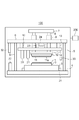
図1は、平坦化装置100の構成を示す概略図である。平坦化装置100は、型11(モールド、テンプレート)を用いて基板1上の組成物を成形する成形装置で具現化され、本実施形態では、基板上の組成物を平坦化する。平坦化装置100は、基板上の組成物と型とを接触させた状態で組成物を硬化させ、硬化した組成物と型を引き離すことで基板上に組成物の大局的又は局所的な平坦面を形成する。
FIG. 1 is a schematic diagram showing the configuration of the
基板は、シリコンウエハが代表的な基材であるが、これに限定されるものではない。基板1は、アルミニウム、チタン−タングステン合金、アルミニウム−ケイ素合金、アルミニウム−銅−ケイ素合金、酸化ケイ素、チッ化ケイ素等の半導体デバイス用基板として知られているものの中からも任意に選択することができる。なお、基板1には、シランカップリング処理、シラザン処理、有機薄膜の成膜、等の表面処理により密着層を形成し、硬化性組成物との密着性を向上させた基板を用いてもよい。なお、基板1は、典型的には、直径300mmの円形であるが、これに限定されるものではない。
The substrate is typically a silicon wafer, but is not limited to this. The
型11としては、光照射工程を考慮して光透過性の材料で構成された型を用いるとよい。型11を構成する材料の材質としては、具体的には、ガラス、石英、PMMA(Polymethyl methacrylate)、ポリカーボネート樹脂等の光透明性樹脂、透明金属蒸着膜、ポリジメチルシロキサン等の柔軟膜、光硬化膜、金属膜等が好ましい。なお、型11は、300mmよりも大きく、500mmよりも小さい直径の円形が好ましいが、これに限られない。また、型11の厚さは、好適には、0.25mm以上2mm未満であるが、これに限られない。
As the
組成物としては、光照射工程を考慮してUV硬化性液体を用いるとよい。典型的にはアクリレートやメタクリレートのようなモノマーを用いてもよい。 As the composition, a UV curable liquid is preferably used in consideration of a light irradiation step. Typically, monomers such as acrylates and methacrylates may be used.
平坦化装置100は、図1に示すように、チャック2、基板ステージ3、ベース定盤4、支柱5、天板6、ガイドバープレート7、ガイドバー8、型駆動部9、支柱10、型チャック12、ヘッド13と、アライメント棚14を有する。また、平坦化装置100は、液滴供給部20、オフアクシスアライメント(OA)スコープ21、基板搬送部22、アライメントスコープ23、光源24、ステージ駆動部31、型搬送部32、洗浄部33と、制御部200を有する。チャック2及び基板ステージ3は、基板1を保持する基板保持部を構成し、型チャック12及びヘッド13は、型11を保持する型保持部を構成する。ここでは、水平面をXY平面とし、鉛直方向をZ軸方向とするようにXYZ座標系が定義されている。
As shown in FIG. 1, the
図1を参照するに、基板1は、搬送ハンドなどを含む基板搬送部22によって、平坦化装置100の外部やウエハが格納された格納箱から搬入され、チャック2に保持される。基板ステージ3は、ベース定盤4に支持され、チャック2に保持された基板1を所定の位置に位置決めするために、X軸方向及びY軸方向に駆動される。ステージ駆動部31は、例えば、リニアモータやエアシリンダなどを含み、基板ステージ3を少なくともX軸方向及びY軸方向に駆動する(移動させる)が、基板ステージ3を2軸以上の方向(例えば、6軸方向)に駆動する機能を有していてもよい。また、ステージ駆動部31は、回転機構を含み、チャック2又は基板ステージ3をZ軸方向に平行な軸周りに回転駆動する(回転させる)。
Referring to FIG. 1, a
型11は、搬送ハンドなどを含む型搬送部32によって、平坦化装置100の外部や型が格納された格納箱から搬入され、型チャック12に保持される。型11は、例えば、円形又は四角形の外形を有し、下面に平面部11aを含む。平面部11aは、基板上の組成物に接触して基板1の表面形状に倣うような剛性を有する。平面部11aは、基板1と同じ大きさ、又は、基板1よりも大きい大きさを有する。型チャック12は、ヘッド13に支持され、型11のZ軸周りの傾きを補正する機能を有する。型チャック12及びヘッド13のそれぞれは、光源24からコリメータレンズを介して照射される光(紫外線)を通過させる開口を含む。また、型チャック12又はヘッド13には、基板上の組成物に対する型11の押し付け力(押印力)を計測するためのロードセルが配置されている。
The
ベース定盤4には、天板6を支持する支柱5が配置されている。ガイドバー8は、天板6を貫通し、一端がガイドバープレート7に固定され、他端がヘッド13に固定される。型駆動部9は、ガイドバー8を介して、ヘッド13をZ軸方向に駆動して、型チャック12に保持された型11を基板上の組成物に接触させたり、基板上の組成物から引き離したりする機構である。また、型駆動部9は、ヘッド13をX軸方向及びY軸方向に駆動する(移動させる)機能、及び、型チャック12又はヘッド13をZ軸方向に平行な軸周りに回転駆動する機能を有する。
On the
アライメント棚14は、支柱10を介して天板6に懸架される。アライメント棚14には、ガイドバー8が貫通している。また、アライメント棚14には、例えば、斜入射像ずれ方式を用いて、チャック2に保持された基板1の高さ(平坦度)を計測するための高さ計測系(不図示)が配置されている。
The
OAスコープ21は、アライメント棚14に支持される。OAスコープ21は、基板1の複数のショット領域に設けられたアライメントマークを検出し、複数のショット領域のそれぞれの位置を決定するグローバルアライメント処理に用いられる。
The
アライメントスコープ23は、基板ステージ3に設けられた基準マークと、型11に設けられたアライメントマークとを観察するための光学系及び撮像系を含む。但し、型11にアライメントマークが設けられていない場合には、アライメントスコープ23がなくてもよい。アライメントスコープ23は、基板ステージ3に設けられた基準マークと、型11に設けられたアライメントマークとの相対的な位置を計測し、その位置ずれを補正するアライメントに用いられる。アライメントスコープ23によって型11と基板ステージ3との位置関係を求め、OAスコープ21によって基板ステージ3と基板1との位置関係を求めることで、型11と基板1との相対的なアライメントを行うことができる。
The
液滴供給部20は、基板1に未硬化(液状)の組成物を吐出する吐出口(ノズル)を含むディスペンサで構成され、基板上に組成物の液滴を滴下して配置(供給)する。液滴供給部20は、例えば、ピエゾジェット方式やマイクロソレノイド方式などを採用し、基板上に微小な容積の液滴状の組成物を供給することができる。また、液滴供給部20における吐出口の数は、限定されるものではなく、1つ(シングルノズル)であってもよいし、100を超えてもよい。即ち、リニアノズルアレイでもよいし、複数のリニアノズルアレイを組み合わせてもよい。
The
洗浄部33は、型11が型チャック12に保持された状態で、型11を洗浄する(クリーニングする)。洗浄部33は、基板上の硬化した組成物から型11を引き離すことによって、型11、特に、平面部11aに付着した組成物を除去する。洗浄部33は、例えば、型11に付着した組成物を拭き取ってもよいし、UV照射、ウェット洗浄、プラズマ洗浄などを用いて型11に付着した組成物を除去してもよい。
The
制御部200は、CPUや他のプロセッサ、FPGAなどの処理部や、メモリなどの記憶部を含み、平坦化装置100の全体を制御する。制御部200は、平坦化装置100の各部を統括的に制御して平坦化処理を行う処理部として機能する。ここで、平坦化処理とは、型11の平面部11aを基板上の組成物に接触させて平面部11aを基板1の表面形状に倣わせることで組成物を平坦化する処理である。なお、平坦化処理は、一般的には、ロット単位で、即ち、同一のロットに含まれる複数の基板のそれぞれに対して行われる。
The
次に、図2(a)乃至図2(c)を参照して、平坦化処理について概要を説明する。本実施形態では、基板全面上の組成物と型を接触させて、組成物を平坦化させる処理について説明するが、基板の一部の領域上の組成物と型を接触させて、組成物を平坦化させてもよい。 Next, an outline of the flattening process will be described with reference to FIGS. In the present embodiment, a process in which the composition and the mold on the entire surface of the substrate are brought into contact with each other and the composition is planarized will be described. It may be flattened.
まず、図2(a)に示すように、下地パターンが形成されている基板1に対して、液滴供給部20から組成物IMの複数の液滴を滴下する。図2(a)は、基板上に組成物IMを供給し、型11を接触させる前の状態を示している。次いで、図2(b)に示すように、基板上の組成物IMと型11の平面部11aとを接触させる。図2(b)は、型11の平面部11aが基板上の組成物IMにすべて接触し、型11の平面部11aが基板1の表面形状に倣った状態を示している。そして、図2(b)に示す状態で、光源24から、型11を介して、基板上の組成物IMに光を照射して組成物IMを硬化させる。次に、図2(c)に示すように、基板上の硬化した組成物IMから型11を引き離す。これにより、基板1の全面で均一な厚みの組成物IMの平坦化層を形成することができる。図2(c)は、基板上に組成物IMの平坦化層が形成された状態を示している。
First, as shown in FIG. 2A, a plurality of droplets of the composition IM are dropped from the
このような平坦化処理を行う際、大面積の型11と基板1全面の組成物とを接触させてから、当該全面において引きはがすことは困難である。接触面積が大きければ大きいほど引きはがすのに要する力(離型力)大きくなる。離型力が大きくなると離型動作自体を正常に行うことができなかったり、基板上の組成物が正常に平坦化されなかったりする。
When performing such a planarization process, it is difficult to bring the large-
このような問題を解決するために、本実施形態では、基板1の外周領域に組成物IMを多数滴下し、組成物IMの分布で基板の内側領域に対して高さの高低差を作り、型と組成物が接触する時に型11又は基板1が反った状態になるようにする。基板1の外周領域において反った状態だと型と組成物の剥離が開始される離型開始点となり、容易に離型しやすくする。一度、型11と基板1の剥離が開始されれば、十分な時間だけ処理すれば離型は完了し、所望の厚さ、平坦さを有する組成物IMが得られる。
In order to solve such a problem, in the present embodiment, a large number of the compositions IM are dropped on the outer peripheral area of the
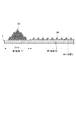
図3に示すように、液滴供給部20は、基板の外形の中心位置Cを含む第1領域1aと、第1領域1aより外側の第2領域1bの上に組成物IMの複数の液滴を配置する。組成物IMを滴下する際に基板1の外周領域に多く滴下するようにする。具体的には、第2領域1b上において組成物の液滴を積み重ねることによって第1領域1aに配置される組成物よりも厚くなるように第2領域1b上に組成物を配置する。図3には、第2領域1b上に組成物を積み重ねた様子(堆積状態)を示す。液滴供給部20は、第2領域1b上で、複数回走査、又は、第2領域1bの上の所定の位置で連続して、組成物IMの液滴を配置することによって第2領域1b上に組成物の液滴を積み重ねる。
As shown in FIG. 3, the
基板1の第1領域1a上に液滴を滴下する場合、第1領域1a部の下地のパターン密度(粗密)と、組成物IMが型によって平坦化されたときの平坦化層の最終的な厚さを計算して、全体の滴下量と滴下位置が求められる。また、本実施形態では、基板1の第2領域1bの基板最外周端から2mm以内、または3mm以内の幅に滴下量を多くして、第1領域1aの滴下量の数倍以上となるように滴下する。
When a droplet is dropped on the
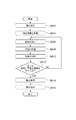
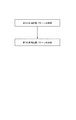
次に、平坦化装置に用いられる、基板上に組成物を滴下するための液滴配置パターンのデータを、作成する方法について、図7を用いて説明する。図7は、液滴配置パターンのデータの作成方法のフローチャートである。液滴配置パターンのデータは、予め外部のコンピュータ(情報処理装置)又は平坦化装置100の制御部(情報処理装置)が作成する。外部のコンピュータが液滴配置パターンのデータを作成した場合は、平坦化装置100の制御部が外部のコンピュータから液滴配置パターンのデータを取得する。情報処理装置は、基板の中心位置を含む第1領域1a上に、液滴供給部20によって組成物を滴下するための第1の液滴配置パターンのデータを作成する。第1の液滴配置パターンは、第1領域1a部の下地のパターンの密度(粗密)やピッチ、幅などと、組成物IMが型によって平坦化されたときの平坦化層の最終的な厚さに基づいて求められる。
Next, a method for creating data of a droplet arrangement pattern for dropping a composition onto a substrate, which is used in a planarization apparatus, will be described with reference to FIG. FIG. 7 is a flowchart of a method for creating data of a droplet arrangement pattern. The data of the droplet arrangement pattern is created in advance by an external computer (information processing device) or a control unit (information processing device) of the
また、液滴供給部20によって第2領域1b上に組成物を滴下するための第2の液滴配置パターンのデータを作成する。第2の液滴配置パターンは、第2領域1b上において組成物の液滴を積み重ねることによって第1領域1aに配置される組成物よりも厚くなるように作成される。具体的には、図3に示すように、第2領域1b上で組成物の液滴を隙間なく配置するような液滴配置パターンを作成する。また、第2領域1b上に組成物の液滴を積み重ねるために複数回走査するときの液滴パターンも作成する。また、第2領域1bの上の所定の位置で連続して組成物IMの液滴を吐出するような、第2の液滴配置パターンを作成してもよい。
Further, data of a second droplet arrangement pattern for dropping the composition onto the second region 1b by the
また、第2の液滴配置パターンは、第1の液滴配置パターンに基づいて作成してもよい。具体的には、第1の液滴配置パターンに基づいて滴下された第1領域1a上の組成物と型を接触させたときの第1領域1a上の組成物の厚さを求める。そして、第2の液滴配置パターンに基づいて滴下された第2領域1b上の組成物と型を接触させたときに第2領域1bにおける組成物の厚さが、求めた第1領域1a上の組成物の厚さよりも厚くなるように第2の液滴配置パターンを作成してもよい。
Further, the second droplet arrangement pattern may be created based on the first droplet arrangement pattern. Specifically, the thickness of the composition on the
次に、平坦化装置100の型や基板の駆動機構を用いて、第1領域1a上の組成物及び第2領域1b上において積み重ねて配置された組成物と型を接触させて、第1領域1a上の組成物を平坦化させてから、第1領域1a及び第2領域1b上の組成物と型を離す。
Next, using the mold of the
図4は、図3の組成物IMを滴下した後に、型11と基板1を全面接触させた状態を表す断面図である。基板1外周の組成物IMの滴下量が多い為、基板1外周において、型11と基板1が平行状態にならず、型11が反っている状態となる。型と基板上の組成物が接触したとき、基板1外周部の組成物IMの厚さは、第1領域1aにおける組成物IMの厚さの数倍以上、例えば1um以上となるようにする。この状態で離型することにより、型11が反っているので、離型開始点が簡単に作られる。更に、基板1外周部に組成物IMが多数滴下されている為、組成物の中に存在する離型材が型11の表面に多く付着する。そのため、第2領域1bにおける組成物と型とを離すときのエネルギーは、第1領域1aの組成物から離型するときや、第2領域1bにも第1領域1aと同じ厚さで組成物を滴下したとき、よりも離型エネルギーが小さくなり、更に離型しやすくなる。
FIG. 4 is a cross-sectional view illustrating a state in which the
図5を参照して、平坦化装置100における平坦化処理について説明する。平坦化処理は、上述したように、制御部200が平坦化装置100の各部を統括的に制御することで行われる。
With reference to FIG. 5, a flattening process in the
S602では、型搬送部32によって、平坦化装置100に型11を搬入し、型11を型チャック12に保持させる。S604では、平坦化処理に関する設定情報を取得する。平坦化処理に関する設定情報は、基板1の第1領域1aに既に形成された下地のパターンの密度(周期や幅など)の情報を含む。また、組成物IMの最終厚さ(硬化時の厚さ)、最外周部(第2領域1b)の最大厚さ、最外周部の組成物が厚くなっている幅、次の平坦化時に最外周部の組成物の最大厚さをどの程度増やすか、などを含みうる。
In S <b> 602, the
S606では、基板搬送部22によって、同一のロットに含まれる複数の基板のうち、処理対象の基板1を平坦化装置100に搬入し、基板1をチャック2に保持させる。S608では、S606で搬入された基板1に対して、図2(a)乃至図2(c)を参照して説明したような平坦化処理を行う。ただし、本実施形態では、第2領域1b上に組成物が積み重ねて配置されているので、型と組成物の接触時は図4に示すように型が外周において上方向に向いた状態となる。つまり、S608では、第1領域1aと第2領域1bの上に組成物の複数の液滴を配置する第1工程と、組成物と型を接触させて組成物を平坦化させてから組成物と型を離す第2工程と、により、型を用いて基板上の組成物を平坦化する。第1工程において、第2領域上において組成物の液滴を積み重ねることによって第1領域に配置される組成物よりも厚くなるように第2領域上に組成物を配置する。第2工程において、第1領域上の組成物及び第2領域上において積み重ねて配置された組成物と型とを接触させて、型を介して硬化光を照射して組成物を硬化させる。そして、第1領域上の組成物を平坦化させてから、第1領域及び第2領域上の組成物と型とを離す。
In step S <b> 606, the
S610では、基板搬送部22によって、平坦化処理が行われた基板1をチャック2から搬出する。S612では、同一のロットに含まれる全ての基板に対して平坦化処理を行ったかどうかを判定する。同一のロットに含まれる全ての基板に対して平坦化処理を行っていない場合には、次の処理対象の基板1をチャック2に配置するために、S606に移行する。一方、同一のロットに含まれる全ての基板に対して平坦化処理を行っている場合には、S614に移行する。
In S610, the
S614では、洗浄部33によって、型チャック12に保持されている型11を洗浄する。即ち、型11の平面部11aに付着した組成物を除去する。S616では、型搬送部32によって、平坦化装置100から、洗浄された型11を搬出する。
In S614, the
更に、本実施形態では離型後に型11と基板1側に以下の特別な処理を行うことができる。基板1側には基板1最外周部に多数の組成物IMを滴下するので、離型後に型11に組成物IMが付着する可能性が高い。したがって、次の基板1の平坦化処理時は、基板1最外周の組成物IMの滴下量を増やして、既に型に付着している付着物が平坦化処理を阻害しないようにする。つまり、前の基板に対して液滴供給部20が吐出して第2領域1bに配置した液滴の数よりも、当該液滴の数多くする。
Further, in the present embodiment, the following special processing can be performed on the
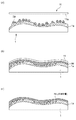
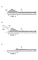
離型後の基板1側には、基板1外周部には数um以上の固化した組成物IMが残っている。図6(a)は離型後の基板1上の組成物IMを示す図である。基板1の第2領域1bの組成物IMは第1領域1a部のIMより厚い形状になる為、基板1の第2領域1bに組成物IMを滴下した時、又は、型と組成物を接触させたときに、基板1の外周端部に組成物IMのはみ出し(染み出し)400が発生している可能性がある。
On the
そこで、本実施形態では、平坦化装置100内、または塗布装置でEBR(Edge Bead Removal)処理を行う。EBRとは、フォトリソグラフィープロセスのレジスト塗布工程で行う周知の工程であり、基板へのレジスト(組成物)の塗布後の基板に対して、基板外周部の薬液(組成物)を除去するために、リンス液を用いて基板外周部のみの組成物を剥離する工程である。図6(b)は、平坦化装置100、または、塗布装置などの外部装置内のEBR処理時の基板1上の組成物を表す図である。リンスノズル500で、リンス液501を用いて、基板1外周部の厚い組成物IMをリンスし、除去する。
Therefore, in the present embodiment, an EBR (Edge Bead Removal) process is performed in the
図6(c)は、EBR後の基板1上の組成物IMである。基板1外周部の厚い組成物IMはほぼ除去された状態である。除去後の組成物の形状は、通常の生産で使用されているフォトリソグラフィーのEBRと同等の形状となる。本実施形態では、基板1外周部にある組成物IMが多数滴下された部分のみを剥離し、基板が次の工程に搬送される。
FIG. 6C shows the composition IM on the
なお、本実施形態では、同一のロットに含まれる全ての基板1に対する平坦化処理が終了し、平坦化装置100から型11を搬出する前に型11を洗浄しているが、これに限定されるものではない。例えば、同一のロットに含まれる全ての基板1に対して平坦化処理が終了していなくても、型11を洗浄するようにしてもよい。また、型11の平面部11aにおける組成物の付着状態を検出する検出部を平坦化装置100が備えている場合には、検出部の検出結果に応じて、型11を洗浄するようにしてもよい。
In the present embodiment, the flattening process is completed on all the
本実施形態では平坦化装置について記載しているが、パターンが形成された型を用いて基板全面を一括してインプリントする一括インプリントにも適用しうる。また、光硬化方式について記載しているが、熱硬化方式にも適用しうる。 In the present embodiment, the flattening apparatus is described. However, the present invention can also be applied to a batch imprint that collectively imprints the entire surface of a substrate using a mold on which a pattern is formed. Further, although the light curing method is described, the invention can also be applied to a heat curing method.
(物品製造方法)
次に、前述の平坦化装置又は平坦化方法を利用した物品(半導体IC素子、液晶表示素子、カラーフィルタ、MEMS等)の製造方法を説明する。当該製造方法は、前述の平坦化装置を使用して、基板(ウェハ、ガラス基板等)に配置された組成物と型を接触させて平坦化させ、組成物を硬化させて組成物と型を離す工程とを含む。そして、平坦化された組成物を有する基板に対して、リソグラフィ装置を用いてパターンを形成するなどの処理を行う工程と、処理された基板を他の周知の加工工程で処理することにより、物品が製造される。他の周知の工程には、エッチング、レジスト剥離、ダイシング、ボンディング、パッケージング等が含まれる。本製造方法によれば、従来よりも高品位の物品を製造することができる。
(Product manufacturing method)
Next, a method for manufacturing an article (semiconductor IC element, liquid crystal display element, color filter, MEMS, etc.) using the above-described flattening apparatus or flattening method will be described. In this manufacturing method, the composition and the mold are brought into contact with the composition disposed on the substrate (wafer, glass substrate, and the like) by using the above-described planarization apparatus, and the composition and the mold are cured. Separating. Then, a step of performing processing such as forming a pattern using a lithography apparatus on the substrate having the planarized composition, and processing the processed substrate in another well-known processing step, Is manufactured. Other well-known steps include etching, resist stripping, dicing, bonding, packaging and the like. According to the present manufacturing method, it is possible to manufacture a higher quality article than before.
以上、本発明の好ましい実施形態について説明したが、本発明はこれらの実施形態に限定されないことはいうまでもなく、その要旨の範囲内で種々の変形及び変更が可能である。 The preferred embodiments of the present invention have been described above. However, it is needless to say that the present invention is not limited to these embodiments, and various modifications and changes can be made within the scope of the gist.
Claims (13)
前記基板の中心位置を含む第1領域と前記第1領域より外側の第2領域の上に組成物の複数の液滴を配置する液滴供給部と、
前記液滴供給部により配置された組成物と型を接触させて組成物を平坦化させてから組成物と型を離す機構と、を有し、
前記液滴供給部は、前記第2領域上において組成物の液滴を積み重ねることによって前記第1領域に配置される組成物よりも厚くなるように前記第2領域上に組成物を配置し、
前記機構は、前記第1領域上の組成物及び前記第2領域上において積み重ねて配置された組成物と型を接触させて、前記第1領域上の組成物を平坦化させてから、前記第1領域及び前記第2領域上の組成物と型を離す、ことを特徴とする平坦化装置。 In a flattening apparatus for flattening the composition on the substrate using a mold,
A droplet supply unit for disposing a plurality of droplets of the composition on a first region including a center position of the substrate and a second region outside the first region;
And a mechanism for separating the composition and the mold after the composition and the mold arranged in contact with the droplet supply unit are brought into contact with each other to flatten the composition.
The droplet supply unit arranges the composition on the second region so as to be thicker than the composition arranged in the first region by stacking the droplets of the composition on the second region,
The mechanism contacts a mold with the composition on the first region and the composition stacked on the second region to planarize the composition on the first region, and then the A flattening apparatus, wherein a mold is separated from a composition on the first region and the second region.
前記機構は、基板全面上の組成物と型を接触させて、前記第1領域の組成物を平坦化させてから、前記基板全面上の組成物と型を離すことを特徴とする請求項1乃至7の何れか1項に記載の平坦化装置。 The droplet supply unit arranges the composition on the entire surface of the substrate,
2. The mechanism according to claim 1, wherein the mold is brought into contact with the composition on the entire surface of the substrate to planarize the composition in the first region, and then the mold is separated from the composition on the entire surface of the substrate. The flattening apparatus according to any one of claims 1 to 7.
前記処理部は、前記基板に形成されたパターンに基づいて前記第1領域及び前記第2領域における前記液滴配置パターンのデータを作成し、
前記液滴供給部は、作成された前記液滴配置パターンのデータに基づいて前記基板上に組成物の液滴を配置することを特徴とする請求項1乃至8の何れか1項に記載の平坦化装置。 A processing unit that creates data of a droplet arrangement pattern for dropping the composition on the substrate,
The processing unit creates data of the droplet arrangement pattern in the first region and the second region based on a pattern formed on the substrate,
9. The liquid droplet supply section according to claim 1, wherein the liquid droplet supply unit arranges the liquid droplets of the composition on the substrate based on data of the created liquid droplet arrangement pattern. 10. Flattening device.
前記基板の中心位置を含む第1領域と前記第1領域より外側の第2領域の上に組成物の複数の液滴を配置する第1工程と、
配置された組成物と型を接触させて組成物を平坦化させてから組成物と型を離す第2工程と、を有し、
前記第1工程において、前記第2領域上において組成物の液滴を積み重ねることによって前記第1領域に配置される組成物よりも厚くなるように前記第2領域上に組成物を配置し、
前記第2工程において、前記第1領域上の組成物及び前記第2領域上において積み重ねて配置された組成物と型とを接触させて、前記第1領域上の組成物を平坦化させてから、前記第1領域及び前記第2領域上の組成物と型とを離す、ことを特徴とする平坦化方法。 In a planarization method for planarizing a composition on a substrate using a mold,
A first step of disposing a plurality of droplets of the composition on a first region including a center position of the substrate and a second region outside the first region;
A second step of releasing the composition and the mold after the composition and the mold are placed in contact with each other to level the composition and
In the first step, disposing the composition on the second region so as to be thicker than the composition disposed on the first region by stacking the droplets of the composition on the second region,
In the second step, the composition on the first region and the composition stacked on the second region are brought into contact with a mold to planarize the composition on the first region, And separating the mold from the composition on the first region and the second region.
平坦化された組成物を有する基板を処理する工程と、
処理された基板から物品を得ることを特徴とする物品の製造方法。 Flattening the composition of the substrate using the flattening method according to claim 11,
Processing a substrate having the planarized composition;
A method for manufacturing an article, comprising obtaining an article from a processed substrate.
前記基板の中心位置を含む第1領域上に組成物を配置するための第1の液滴配置パターンのデータを作成する工程と、
前記第1領域より外側の第2領域上に組成物を配置するための第2の液滴配置パターンのデータを作成する工程と、を有し、
前記第2の液滴配置パターンを、前記第2領域上において組成物の液滴を積み重ねることによって前記第1領域に配置される組成物よりも厚くなるように作成する、ことを特徴とする作成方法。 In a creation method of creating data of a droplet arrangement pattern for dropping a composition on a substrate in a flattening apparatus that flattens a composition on a substrate using a mold,
Creating data of a first droplet arrangement pattern for arranging a composition on a first region including a center position of the substrate;
Generating data of a second droplet arrangement pattern for arranging the composition on the second area outside the first area,
Forming the second droplet arrangement pattern such that the composition droplets are stacked on the second region so as to be thicker than the composition arranged in the first region. Method.
Priority Applications (1)
| Application Number | Priority Date | Filing Date | Title |
|---|---|---|---|
| JP2018123745A JP7071231B2 (en) | 2018-06-28 | 2018-06-28 | Flattening device, flattening method, article manufacturing method, and method for creating droplet placement pattern data |
Applications Claiming Priority (1)
| Application Number | Priority Date | Filing Date | Title |
|---|---|---|---|
| JP2018123745A JP7071231B2 (en) | 2018-06-28 | 2018-06-28 | Flattening device, flattening method, article manufacturing method, and method for creating droplet placement pattern data |
Publications (2)
| Publication Number | Publication Date |
|---|---|
| JP2020004877A true JP2020004877A (en) | 2020-01-09 |
| JP7071231B2 JP7071231B2 (en) | 2022-05-18 |
Family
ID=69100437
Family Applications (1)
| Application Number | Title | Priority Date | Filing Date |
|---|---|---|---|
| JP2018123745A Active JP7071231B2 (en) | 2018-06-28 | 2018-06-28 | Flattening device, flattening method, article manufacturing method, and method for creating droplet placement pattern data |
Country Status (1)
| Country | Link |
|---|---|
| JP (1) | JP7071231B2 (en) |
Cited By (1)
| Publication number | Priority date | Publication date | Assignee | Title |
|---|---|---|---|---|
| JP2022041583A (en) * | 2020-09-01 | 2022-03-11 | キヤノン株式会社 | Planarization device, planarization method, manufacturing method for article, and computer program |
Citations (13)
| Publication number | Priority date | Publication date | Assignee | Title |
|---|---|---|---|---|
| JPS5512750A (en) * | 1978-07-12 | 1980-01-29 | Mitsubishi Electric Corp | Resist application device |
| JPH09293715A (en) * | 1996-04-26 | 1997-11-11 | Sanyo Electric Co Ltd | Method for manufacturing semiconductor device |
| JP2003273092A (en) * | 2002-03-15 | 2003-09-26 | Seiko Epson Corp | Film forming method, film forming apparatus, device manufacturing method, and electronic equipment |
| WO2004070811A1 (en) * | 2003-02-06 | 2004-08-19 | Semiconductor Energy Laboratory Co., Ltd. | Semiconductor producing apparatus |
| JP2005532576A (en) * | 2002-02-27 | 2005-10-27 | ブルーワー サイエンス アイ エヌ シー. | A novel planarization method for multilayer lithography processes |
| JP2006212859A (en) * | 2005-02-02 | 2006-08-17 | Matsushita Electric Ind Co Ltd | Molding method and molding apparatus |
| JP2008529826A (en) * | 2005-01-31 | 2008-08-07 | モレキュラー・インプリンツ・インコーポレーテッド | Chucking system for nano machining |
| US20090166933A1 (en) * | 2007-12-28 | 2009-07-02 | Molecular Imprints, Inc. | Template Pattern Density Doubling |
| JP2011529626A (en) * | 2008-06-09 | 2011-12-08 | ボード・オブ・リージエンツ,ザ・ユニバーシテイ・オブ・テキサス・システム | Adaptive nanotopography sculpting |
| JP2012532448A (en) * | 2009-07-02 | 2012-12-13 | モレキュラー・インプリンツ・インコーポレーテッド | Chucking system with recessed support features |
| JP2013211450A (en) * | 2012-03-30 | 2013-10-10 | Dainippon Printing Co Ltd | Process of manufacturing substrate and process of manufacturing template for nanoimprint lithography |
| JP2016078019A (en) * | 2014-10-10 | 2016-05-16 | 住友重機械工業株式会社 | Film forming device and film forming method |
| JP2016178127A (en) * | 2015-03-18 | 2016-10-06 | キヤノン株式会社 | Imprint system and method for manufacturing article |
-
2018
- 2018-06-28 JP JP2018123745A patent/JP7071231B2/en active Active
Patent Citations (13)
| Publication number | Priority date | Publication date | Assignee | Title |
|---|---|---|---|---|
| JPS5512750A (en) * | 1978-07-12 | 1980-01-29 | Mitsubishi Electric Corp | Resist application device |
| JPH09293715A (en) * | 1996-04-26 | 1997-11-11 | Sanyo Electric Co Ltd | Method for manufacturing semiconductor device |
| JP2005532576A (en) * | 2002-02-27 | 2005-10-27 | ブルーワー サイエンス アイ エヌ シー. | A novel planarization method for multilayer lithography processes |
| JP2003273092A (en) * | 2002-03-15 | 2003-09-26 | Seiko Epson Corp | Film forming method, film forming apparatus, device manufacturing method, and electronic equipment |
| WO2004070811A1 (en) * | 2003-02-06 | 2004-08-19 | Semiconductor Energy Laboratory Co., Ltd. | Semiconductor producing apparatus |
| JP2008529826A (en) * | 2005-01-31 | 2008-08-07 | モレキュラー・インプリンツ・インコーポレーテッド | Chucking system for nano machining |
| JP2006212859A (en) * | 2005-02-02 | 2006-08-17 | Matsushita Electric Ind Co Ltd | Molding method and molding apparatus |
| US20090166933A1 (en) * | 2007-12-28 | 2009-07-02 | Molecular Imprints, Inc. | Template Pattern Density Doubling |
| JP2011529626A (en) * | 2008-06-09 | 2011-12-08 | ボード・オブ・リージエンツ,ザ・ユニバーシテイ・オブ・テキサス・システム | Adaptive nanotopography sculpting |
| JP2012532448A (en) * | 2009-07-02 | 2012-12-13 | モレキュラー・インプリンツ・インコーポレーテッド | Chucking system with recessed support features |
| JP2013211450A (en) * | 2012-03-30 | 2013-10-10 | Dainippon Printing Co Ltd | Process of manufacturing substrate and process of manufacturing template for nanoimprint lithography |
| JP2016078019A (en) * | 2014-10-10 | 2016-05-16 | 住友重機械工業株式会社 | Film forming device and film forming method |
| JP2016178127A (en) * | 2015-03-18 | 2016-10-06 | キヤノン株式会社 | Imprint system and method for manufacturing article |
Cited By (2)
| Publication number | Priority date | Publication date | Assignee | Title |
|---|---|---|---|---|
| JP2022041583A (en) * | 2020-09-01 | 2022-03-11 | キヤノン株式会社 | Planarization device, planarization method, manufacturing method for article, and computer program |
| JP7512132B2 (en) | 2020-09-01 | 2024-07-08 | キヤノン株式会社 | Planarization apparatus, planarization method, article manufacturing method, and computer program |
Also Published As
| Publication number | Publication date |
|---|---|
| JP7071231B2 (en) | 2022-05-18 |
Similar Documents
| Publication | Publication Date | Title |
|---|---|---|
| JP7033994B2 (en) | Molding equipment and manufacturing method of articles | |
| KR102955706B1 (en) | Forming apparatus, forming method, and article manufacturing method | |
| US20260010069A1 (en) | Molding apparatus, molding method, and template | |
| JP2024160394A (en) | Foreign matter removal method, foreign matter removal device, and article manufacturing method | |
| KR102571412B1 (en) | Planarization apparatus, planarization method, and article manufacturing method | |
| JP7218114B2 (en) | Flattening apparatus, flattening method and article manufacturing method | |
| US12214529B2 (en) | Conveyance apparatus, planarization apparatus, and article manufacturing method | |
| JP7071231B2 (en) | Flattening device, flattening method, article manufacturing method, and method for creating droplet placement pattern data | |
| JP7551694B2 (en) | Foreign matter removal method, foreign matter removal device, and article manufacturing method | |
| JP7446934B2 (en) | Mold, flattening device, flattening method, and article manufacturing method | |
| JP7410616B2 (en) | Flattening device, article manufacturing method, flattening method, and imprint device | |
| JP7237519B2 (en) | Molding apparatus for molding composition on substrate using mold, molding method, and article manufacturing method | |
| JP2020047649A (en) | Molding apparatus, molding method, and article manufacturing method, for molding composition on substrate using mold | |
| JP2025038354A (en) | Molding apparatus, molding method, and method for manufacturing an article. | |
| US20250069892A1 (en) | Planarization method and method of manufacturing article | |
| JP7418127B2 (en) | Flattening device, flattening method, and article manufacturing method | |
| US12339584B2 (en) | Substrate conveyance method, substrate conveyance apparatus, molding method, and article manufacturing method | |
| JP7195789B2 (en) | Flattening device and method for manufacturing article | |
| TW202610807A (en) | Film formation method and article manufacturing method | |
| JP7134844B2 (en) | Molding apparatus and article manufacturing method | |
| JP7512132B2 (en) | Planarization apparatus, planarization method, article manufacturing method, and computer program | |
| KR20260066011A (en) | Forming apparatus, forming method, and article manufacturing method | |
| KR20250099658A (en) | Forming apparatus, forming method, and article manufacturing method | |
| JP2026078969A (en) | Lithography system and method for manufacturing articles | |
| JP2025098718A (en) | Molding apparatus, molding method, and article manufacturing method |
Legal Events
| Date | Code | Title | Description |
|---|---|---|---|
| A621 | Written request for application examination |
Free format text: JAPANESE INTERMEDIATE CODE: A621 Effective date: 20210427 |
|
| A977 | Report on retrieval |
Free format text: JAPANESE INTERMEDIATE CODE: A971007 Effective date: 20220215 |
|
| TRDD | Decision of grant or rejection written | ||
| A01 | Written decision to grant a patent or to grant a registration (utility model) |
Free format text: JAPANESE INTERMEDIATE CODE: A01 Effective date: 20220405 |
|
| A61 | First payment of annual fees (during grant procedure) |
Free format text: JAPANESE INTERMEDIATE CODE: A61 Effective date: 20220506 |
|
| R151 | Written notification of patent or utility model registration |
Ref document number: 7071231 Country of ref document: JP Free format text: JAPANESE INTERMEDIATE CODE: R151 |