JP2020005441A - Driving motor and electric vehicle - Google Patents
Driving motor and electric vehicle Download PDFInfo
- Publication number
- JP2020005441A JP2020005441A JP2018124338A JP2018124338A JP2020005441A JP 2020005441 A JP2020005441 A JP 2020005441A JP 2018124338 A JP2018124338 A JP 2018124338A JP 2018124338 A JP2018124338 A JP 2018124338A JP 2020005441 A JP2020005441 A JP 2020005441A
- Authority
- JP
- Japan
- Prior art keywords
- rotor
- driving motor
- stator
- moving body
- inner peripheral
- Prior art date
- Legal status (The legal status is an assumption and is not a legal conclusion. Google has not performed a legal analysis and makes no representation as to the accuracy of the status listed.)
- Pending
Links
Images




Classifications
-
- H—ELECTRICITY
- H02—GENERATION; CONVERSION OR DISTRIBUTION OF ELECTRIC POWER
- H02K—DYNAMO-ELECTRIC MACHINES
- H02K7/00—Arrangements for handling mechanical energy structurally associated with dynamo-electric machines, e.g. structural association with mechanical driving motors or auxiliary dynamo-electric machines
- H02K7/10—Structural association with clutches, brakes, gears, pulleys or mechanical starters
- H02K7/12—Structural association with clutches, brakes, gears, pulleys or mechanical starters with auxiliary limited movement of stators, rotors or core parts, e.g. rotors axially movable for the purpose of clutching or braking
Landscapes
- Engineering & Computer Science (AREA)
- Power Engineering (AREA)
- Permanent Magnet Type Synchronous Machine (AREA)
- Connection Of Motors, Electrical Generators, Mechanical Devices, And The Like (AREA)
Abstract
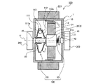
【課題】ロータの回転軸方向におけるロータとステータとの相対的位置を変更でき、製造コストを抑制することができる駆動用電動機、及び該駆動用電動機を備えた電動車両を得る。【解決手段】本発明に係る駆動用電動機は、電動車両の車輪を回転させる駆動力を発生させる駆動用電動機であって、回転軸を中心に回転するロータと、ステータと、前記ロータ及び前記ステータのうちで内周側に配置された方である内周側部品を前記回転軸方向に移動させる移動装置と、を備え、前記移動装置は、少なくとも一部の部材が前記ロータと共に回転し、該回転によって慣性力が作用する慣性力作用部を含み、前記内周側部品は、前記慣性力によって、前記回転軸方向に移動する構成となっている。【選択図】図2A driving motor that can change a relative position between a rotor and a stator in a rotation axis direction of the rotor and can reduce manufacturing cost, and an electric vehicle including the driving motor. A driving motor according to the present invention is a driving motor for generating a driving force for rotating wheels of an electric vehicle, wherein the rotor rotates about a rotating shaft, a stator, the rotor and the stator. A moving device for moving the inner peripheral part, which is the one arranged on the inner peripheral side, in the direction of the rotation axis, wherein the moving device rotates at least a part of the members together with the rotor, An inertial force acting portion on which an inertial force acts by rotation is provided, and the inner peripheral part is configured to move in the rotation axis direction by the inertial force. [Selection] Figure 2
Description
本発明は、電動車両の車輪を回転させる駆動力を発生させる駆動用電動機、及び、該駆動用電動機を備えた電動車両に関する。 The present invention relates to a driving motor for generating a driving force for rotating wheels of an electric vehicle, and an electric vehicle including the driving motor.
近年の車両には、車輪を回転させる駆動源として電動機を備えた電動車両が提案されている。そして、電動車両の車輪を回転させる駆動力を発生させる駆動用電動機では、ロータが高速回転した際に生じる逆起電力を低減するために様々な提案がなされている。例えば、特許文献1に記載の駆動用電動機は、ステータをロータの回転軸方向に移動させることにより、ロータとステータとの相対的位置を変更でき、ロータの磁石とステータのコイルとの対向面積を変更できる構成となっている。このように駆動用電動機を構成することにより、ロータを高速回転させる際にロータの磁石とステータのコイルとの対向面積を小さくすることで、逆起電力を低減することができる。 In recent years, an electric vehicle provided with an electric motor as a driving source for rotating wheels has been proposed. Various proposals have been made for a driving motor for generating a driving force for rotating wheels of an electric vehicle in order to reduce a back electromotive force generated when a rotor rotates at a high speed. For example, in the drive motor described in Patent Document 1, the relative position between the rotor and the stator can be changed by moving the stator in the rotation axis direction of the rotor, and the facing area between the magnet of the rotor and the coil of the stator can be reduced. It has a configuration that can be changed. By configuring the driving motor in this way, the back electromotive force can be reduced by reducing the facing area between the magnet of the rotor and the coil of the stator when rotating the rotor at high speed.
特許文献1に記載の駆動用電動機は、ステータをロータの回転軸方向に移動させるアクチュエータが必要である。アクチュエータとは、油圧又は電動機を用いた駆動装置である。このため、特許文献1に記載の駆動用電動機は、ステータをロータの回転軸方向に移動させる専用のアクチュエータが必要となり、製造コストが上昇してしまうという課題があった。 The driving motor described in Patent Literature 1 requires an actuator that moves the stator in the rotation axis direction of the rotor. An actuator is a drive device using a hydraulic or electric motor. For this reason, the drive motor described in Patent Literature 1 requires a dedicated actuator for moving the stator in the direction of the rotation axis of the rotor, and has a problem that the manufacturing cost is increased.
本発明は、上述の課題を背景としてなされたものであり、ロータの回転軸方向においてロータとステータとの相対的位置を変更でき、製造コストを抑制することができる駆動用電動機、及び該駆動用電動機を備えた電動車両を得ることを目的とする。 The present invention has been made in view of the above problems, and has a drive motor that can change a relative position between a rotor and a stator in a rotation axis direction of the rotor and can suppress a manufacturing cost. An object is to obtain an electric vehicle including an electric motor.
本発明に係る駆動用電動機は、電動車両の車輪を回転させる駆動力を発生させる駆動用電動機であって、回転軸を中心に回転するロータと、ステータと、前記ロータ及び前記ステータのうちで内周側に配置された方である内周側部品を前記回転軸方向に移動させる移動装置と、を備え、前記移動装置は、少なくとも一部の部材が前記ロータと共に回転し、該回転によって慣性力が作用する慣性力作用部を含み、前記内周側部品は、前記慣性力によって、前記回転軸方向に移動する構成となっている。 A driving motor according to the present invention is a driving motor that generates a driving force for rotating wheels of an electric vehicle, and includes a rotor that rotates around a rotation axis, a stator, and an inner rotor among the rotor and the stator. A moving device for moving an inner peripheral component, which is disposed on the circumferential side, in the direction of the rotation axis, wherein the moving device is configured such that at least a part of the member rotates together with the rotor, and an inertial force is generated by the rotation. The inner peripheral part moves in the rotation axis direction by the inertial force.
また、本発明に係る電動車両は、本発明に係る駆動用電動機と、前記駆動用電動機の駆動力によって回転する車輪と、を備えている。 Further, an electric vehicle according to the present invention includes the driving electric motor according to the present invention, and wheels that are rotated by the driving force of the driving electric motor.
本発明に係る駆動用電動機は、ロータの回転によって発生する慣性力を用いて、ロータの回転軸方向においてロータとステータとの相対的位置を変更する。このため、本発明に係る駆動用電動機は、ロータ又はステータをロータの回転軸方向に移動させるための専用のアクチュエータを必要としない。したがって、本発明に係る駆動用電動機は、ロータの回転軸方向においてロータとステータとの相対的位置を変更でき、且つ、製造コストの上昇を抑制することができる。 The drive motor according to the present invention changes the relative position between the rotor and the stator in the rotation axis direction of the rotor by using inertial force generated by rotation of the rotor. Therefore, the drive motor according to the present invention does not require a dedicated actuator for moving the rotor or the stator in the rotation axis direction of the rotor. Therefore, the driving motor according to the present invention can change the relative position between the rotor and the stator in the rotation axis direction of the rotor, and can suppress an increase in manufacturing cost.
以下、図面を適宜参照しながら本発明の実施の形態について説明する。 Hereinafter, embodiments of the present invention will be described with reference to the drawings as appropriate.
なお、以下では、本発明が電動二輪車に採用される場合を説明するが、本発明は、電動二輪車以外の電動車両(例えば、電動三輪車、電動四輪車等)に採用されてもよい。また、電動車両には、電動自転車も含まれる。電動自転車とは、車輪を駆動する駆動モータを備え、ペダルに付与される踏力によっても路上を推進することができる車両のことである。 In the following, a case where the present invention is applied to an electric motorcycle will be described. However, the present invention may be applied to an electric vehicle other than the electric motorcycle (for example, an electric three-wheeled vehicle, an electric four-wheeled vehicle, etc.). In addition, the electric vehicle includes an electric bicycle. An electric bicycle is a vehicle that includes a drive motor that drives wheels and that can be propelled on the road by a pedaling force applied to a pedal.
また、以下で説明する構成及び動作等は本発明の一例であり、本発明は、そのような構成及び動作等である場合に限定されない。 The configuration, operation, and the like described below are examples of the present invention, and the present invention is not limited to such a configuration, operation, and the like.
また、各図において、同一又は相当関係にある部材又は部分には、同一の符号を付すか、又は、符号を付すことを省略している。また、各図において、詳細部分の図示が適宜簡略化または省略されている。 In addition, in each of the drawings, the same or corresponding members or portions are denoted by the same reference numerals, or the reference numerals are omitted. In addition, in each of the drawings, illustration of a detailed portion is appropriately simplified or omitted.
実施の形態1.
<電動二輪車の構成>
本実施の形態1に係る電動二輪車200について説明する。
Embodiment 1 FIG.
<Structure of electric motorcycle>
An
図1は、本発明の実施の形態1に係る電動二輪車の概略構成を示す図である。
電動二輪車200は、車体201と、フロントフォーク202を介して車体201に回転自在に接続された前車輪210と、スイングアーム203を介して車体201に回転自在に接続された後車輪220とを備える。
FIG. 1 is a diagram showing a schematic configuration of an electric motorcycle according to Embodiment 1 of the present invention.
The
また、電動二輪車200は、車体201に取り付けられたアクセルレバー204と、車体201に組み込まれた制御装置230と、車体201に組み込まれた電池240と、後車輪220を回転させる駆動力を発生させる駆動用電動機1とを備える。
Further, the
制御装置230は、例えば、マイコン、マイクロプロセッサユニット等を含んで構成されてもよく、また、ファームウェア等の更新可能なものを含んで構成されてもよく、また、CPU等からの指令によって実行されるプログラムモジュール等を含んで構成されてもよい。制御装置230は、アクセルレバー204を介してドライバから入力されるアクセル開度に応じた電流を電池240から駆動用電動機1に供給することによって、駆動用電動機1の回転数を制御するようになっている。
The
<駆動用電動機の構成>
続いて、本実施の形態1に係る駆動用電動機1の構成について説明する。
<Configuration of drive motor>
Next, the configuration of the driving motor 1 according to the first embodiment will be described.
図2及び図3は、本発明の実施の形態1に係る電動二輪車の後車輪の概略構成を示す断面図である。また、図4は、本発明の実施の形態1に係る駆動用電動機の移動装置の第1部材及び移動体を、図2に示すZ方向から観察した図である。図2及び図3は、ロータ10の回転軸11を通り、該回転軸11と平行な仮想平面で後車輪220を切断した図面となっている。ここで、図3は、図2の状態からステータ20がロータ10の回転軸11方向に移動し、ロータ10の磁石12とステータ20のコイル21との対向面積が図2の状態よりも小さくなっている状態を示している。なお、ロータ10の回転軸11方向とは、回転軸11が延びる方向であり、図2及び図3では紙面左右方向となっている。また、ロータ10の磁石12とステータ20のコイル21との対向面積とは、ロータ10の磁石12とステータ20のコイル21とが対向している範囲の面積である。
2 and 3 are cross-sectional views illustrating a schematic configuration of a rear wheel of the electric motorcycle according to Embodiment 1 of the present invention. FIG. 4 is a view of the first member and the moving body of the moving device for the driving electric motor according to Embodiment 1 of the present invention when viewed from the Z direction shown in FIG. 2 and 3 are drawings in which the
駆動用電動機1は、ステータ20と、回転軸11を中心としてステータ20に対して回転するロータ10とを備えている。また、本実施の形態1では、駆動用電動機1は、回転軸11と同軸状に配置されたシャフト30を備えている。このシャフト30は、スイングアーム203に固定されている。
The drive motor 1 includes a
ロータ10は、例えば両端が塞がった、中空の円筒形状をしている。ロータ10は、後車輪220のリムとしても機能する。このロータ10は、回転軸11を中心として回転自在に、シャフト30に取り付けられている。本実施の形態1では、ロータ10は、シャフト30に設けられたラジアル軸受41及びラジアル軸受42を介して、シャフト30に回転自在に取り付けられている。また、ロータ10の環状の外周面には、タイヤ221が接続されている。換言すると、ロータ10は、タイヤ221と接続されている。したがって、駆動用電動機1を駆動すると、ロータ10と共にタイヤ221も回転する。また、ロータ10は、内周面に、後車輪220の周方向に沿って環状に配置された複数の磁石12を有する。なお、ロータ10は、タイヤ221と直接接続されている必要はなく、タイヤ221と共に回転できれば、他の部品を介してタイヤ221と接続されていてもよい。
The
ステータ20は、シャフト30の周りに設けられ、ロータ10の内部空間に収容されている。ステータ20は、外周面に、後車輪220の周方向に沿って環状に配置された複数のコイル21を有する。これら複数のコイル21は、環状に配置された複数の磁石12の内周側に配置され、これら複数の磁石12と対向している。すなわち、駆動用電動機1は、ロータ10がステータ20の外側に設けられるアウターロータ型の電動機である。
The
また、上述のように、ロータ10は、後車輪220のタイヤ221の内周側に配置されて、タイヤ221と接続されている。そして、ロータ10とタイヤ221とが共に回転する。すなわち、駆動用電動機1は、インホイール電動機となっている。なお、以下では、ロータ10及びステータ20のうちで内周側に配置された方を、内周側部品2と称する場合がある。すなわち、本実施の形態1では、ステータ20が内周側部品2となる。
Further, as described above, the
また、内周側部品2であるステータ20は、シャフト30に対して回転せず、回転軸11方向に移動自在となるように、シャフト30に接続されている。本実施の形態1では、ステータ20は、スプライン軸受43を介して、シャフト30に接続されている。
The
ここで、本実施の形態1に係る駆動用電動機1は、ステータ20を回転軸11方向に移動させる機構として、移動装置100を備えている。この移動装置100は、慣性力作用部110及びバネ101を備えている。
Here, the driving motor 1 according to the first embodiment includes a moving
慣性力作用部110には、少なくとも一部の部材がロータ10と共に回転し、該回転によって慣性力が作用する。詳しくは、慣性力作用部110は、第1部材111、第2部材112及び移動体113を備えている。第1部材111は、略円板形状をしており、中心部にシャフト30が貫通している。また、第1部材111は、ロータ10に直接接続されている。すなわち、第1部材111は、ロータ10と共に回転する。なお、ロータ10と共に回転することができれば、第1部材111は、他の部品を介してロータ10に接続されていてもよい。例えば、第1部材111をラジアル軸受41に取り付け、該ラジアル軸受41を介して、第1部材111とロータ10とを接続してもよい。
At least a part of the inertial
第2部材112は、略円板形状をしており、中心部にシャフト30が貫通している。また、第2部材112は、回転軸11方向に第1部材111と対向して配置されている。本実施の形態1では、第2部材112は、第1部材111を基準として、ステータ20側に配置されている。第2部材112は、ステータ20と共に回転軸11方向に移動するものであり、ステータ20と接続されている。具体的には、第2部材112は、後述するスラスト軸受115を介して、スプライン軸受43に接続されている。すなわち、第2部材112は、スラスト軸受115及びスプライン軸受43を介して、ステータ20と接続されている。なお、スラスト軸受115をステータ20に直接接続し、スラスト軸受115を介して第2部材112とステータ20とを接続してもよい。上述のように、第2部材112は、スラスト軸受115を介して、スプライン軸受43に接続されている。すなわち、第2部材112は、ロータ10及び第1部材111と共に回転自在となるように、スプライン軸受43に接続されている。
The
移動体113は、第1部材111と第2部材112との間に配置されている。移動体113は、円筒状のローラである。図4に示すように、第1部材111には、円筒状のローラである移動体113の中心軸方向の両端部と対向する位置に、側壁111cが設けられている。これにより、第1部材111には、側壁111c間に、該第1部材111の中心部から径方向に延びる溝111bが形成されている。移動体113は、当該溝111bに、回転して前記径方向に移動自在に配置されている。すなわち、側壁111c間に、移動体113の収容空間が形成される。このため、ロータ10と共に第1部材111が回転すると、移動体113は、溝111bを形成する側壁111cに押されて、第1部材111と共に回転することとなる。そして、移動体113は、当該回転時に移動体113に作用する慣性力によって、第1部材111の外周側へ移動することとなる。上述のように、第1部材111の中心部には、回転軸11と同軸状に配置されたシャフト30が貫通している。このため、移動体113は、回転時に移動体113に作用する慣性力によって、回転軸11から離れる方向へ移動することとなる。
The moving
なお、溝111b及び移動体113の数は任意であるが、本実施の形態1では、複数の溝111bが第1部材111に形成され、溝111bのそれぞれに移動体113が配置されている。そして、これらの溝111bは、等角度間隔で配置されている。各移動体113が回転し、各移動体113に慣性力が作用した際、該慣性力は、シャフト30を介して、ラジアル軸受41及びラジアル軸受42で支持される。この際、移動体113が配置された複数の溝111bを等角度間隔で配置することにより、各移動体113が回転した際にシャフト30にかかるラジアル方向の荷重の不均衡を抑制でき、各移動体113が回転した際にラジアル軸受41及びラジアル軸受42にかかる荷重を低減することができる。すなわち、例えば、ラジアル軸受41及びラジアル軸受42の損傷を抑制できるという効果を得ることができる。あるいは、ラジアル軸受41及びラジアル軸受42を小型化及び軽量化でき、駆動用電動機1を小型化及び軽量化できるという効果を得ることができる。
Although the number of the
また、本実施の形態1では第1部材111に移動体113の収容空間である溝111bを形成したが、本実施の形態1のように第2部材112がロータ10と共に回転する構成の場合、第2部材112に移動体113の収容空間を形成してもよい。また、移動体113は、回転時に移動体113に作用する慣性力によって回転軸11から離れる方向へ移動できれば、円筒状のローラ以外であってもよい。例えば、移動体113として、球を用いることもできる。また例えば、第1部材111と第2部材112との間の気密性が保たれていれば、移動体113としてオイルを用いてもよい。
Further, in the first embodiment, the
バネ101は、第1部材111と第2部材112とが近づく方向に、内周側部品2に力を付与するものである。上述のように、本実施の形態1では、ステータ20が内周側部品2となっている。このため、本実施の形態1では、バネ101は、第1部材111と第2部材112とが近づく方向に、ステータ20に力を付与する。詳しくは、本実施の形態1では、バネ101として圧縮バネを用いている。そして、バネ101の一方の端部は、シャフト30に設けられた鍔部31に当接している。また、バネ101の他方の端部は、スプライン軸受43に当接している。これにより、ステータ20及びスプライン軸受43は、第1部材111と第2部材112とが近づく方向に押圧される。なお、バネ101は、圧縮バネに限定されない。例えば皿バネ、引張バネ等、第1部材111と第2部材112とが近づく方向にステータ20に力を付与できれば、バネ101として種々のバネを用いることができる。
The
バネ101によってステータ20が押圧されると、ステータ20及び該ステータ20に接続されている第2部材112は、回転軸11方向に、第1部材111へ近づこうとする。そして、図2に示すように、ロータ10が回転していない状態においては、第1部材111と第2部材112との間に移動体113が挟み込まれた状態になると、ステータ20の回転軸11方向の移動が停止する。なお、図2に示すステータ20の位置は、第1部材111と第2部材112とが最も近づく状態であり、ロータ10の磁石12とステータ20のコイル21との対向面積が最も大きい状態となる。なお、この状態から第1部材111と第2部材112とがさらに近づかないように、図示せぬストッパーを設けてもよい。このようなストッパー設ける場合、図2に示す状態において、第1部材111と第2部材112との間に移動体113が挟み込まれていなくてもよい。
When the
ここで、図2及び図3に示すように、第1部材111は、回転軸11から離れるにしたがって第2部材112に近づく傾斜部111aを備えている。また、第2部材112は、回転軸11から離れるにしたがって第1部材111に近づく傾斜部112aを備えている。このため、図2及び図3からわかるように、第1部材111と第2部材112との間に移動体113が挟み込まれた状態となっている際、移動体113が回転軸11から離れるほど、第1部材111と第2部材112とが離れる。すなわち、移動体113が回転軸11から離れるほど、第2部材112と接続されているステータ20の位置が図2の状態から回転軸11方向にずれ、ロータ10の磁石12とステータ20のコイル21との対向面積が小さくなる。
Here, as shown in FIGS. 2 and 3, the
したがって、ロータ10が回転すると、ロータ10の磁石12とステータ20のコイル21との対向面積は、次のように変化することとなる。詳しくは、ロータ10と共に移動体113が回転すると、移動体113は、慣性力によって、回転軸11から離れる方向へ移動しようとする。すなわち、移動体113は、第1部材111と第2部材112との間を押し広げ、第2部材112及びステータ20を、回転軸11方向であってバネ101を縮める方向へ移動させようとする。この際、移動体113が第2部材112及びステータ20を回転軸11方向(図2及び図3において左側から右側へ向かう方向)へ押す力と、バネ101が第2部材112及びステータ20を回転軸11方向(図2及び図3において右側から左側へ向かう方向)へ押す力とが釣り合った位置で、第2部材112及びステータ20は停止する。
Therefore, when the
すなわち、ロータ10及び移動体113の回転数が高くなるほど、移動体113に作用する慣性力は大きくなる。このため、ロータ10及び移動体113の回転数が高くなるほど、移動体113が第1部材111と第2部材112との間を押し広げようとする力が強くなる。したがって、ロータ10及び移動体113の回転数が高くなるほど、ステータ20は図2の状態からの回転軸11方向のずれ量が大きくなり、ロータ10の磁石12とステータ20のコイル21との対向面積が小さくなる。
That is, as the rotation speed of the
<駆動用電動機の動作>
続いて、本実施の形態1に係る駆動用電動機1の動作について説明する。
ドライバがアクセルレバー204を操作すると、制御装置230は、アクセル開度に応じた電流を電池240から駆動用電動機1に供給する。これにより、駆動用電動機1のロータ10が回転する。
<Operation of drive motor>
Next, the operation of the driving motor 1 according to the first embodiment will be described.
When the driver operates the
ロータ10が回転すると、該ロータ10と共に、第1部材111、第2部材112及び移動体113も回転する。これにより、移動体113に慣性力が作用し、移動体113は、慣性力によって、第1部材111と第2部材112との間を押し広げ、回転軸11から離れる方向へ移動しようとする。そして、移動体113が第2部材112及びステータ20を回転軸11方向(図2及び図3において左側から右側へ向かう方向)へ押す力と、バネ101が第2部材112及びステータ20を回転軸11方向(図2及び図3において右側から左側へ向かう方向)へ押す力とが釣り合った位置で、第2部材112及びステータ20は停止する。この際、ロータ10及び移動体113の回転数が高くなるほど、移動体113に作用する慣性力は大きくなる。このため、ロータ10及び移動体113の回転数が高くなるほど、ステータ20は図2の状態からの回転軸11方向のずれ量が大きくなり、ロータ10の磁石12とステータ20のコイル21との対向面積が小さくなる。
When the
<効果>
本実施の形態1に係る駆動用電動機1は、回転軸11を中心に回転するロータ10と、ステータ20と、内周側部品2であるステータ20を回転軸11方向に移動させる移動装置100と、を備えている。移動装置100は、少なくとも一部の部材がロータ10と共に回転し、該回転によって慣性力が作用する慣性力作用部110を含む。そして、内周側部品2であるステータ20は、慣性力作用部110に作用する慣性力によって、回転軸11方向に移動する。
<Effect>
The driving motor 1 according to the first embodiment includes a
本実施の形態1に係る駆動用電動機1は、ロータ10の回転によって発生する慣性力を用いて、回転軸11方向においてロータ10とステータ20との相対的位置を変更する。このため、本実施の形態1に係る駆動用電動機1は、ロータ10又はステータ20を回転軸11方向に移動させるための専用のアクチュエータを必要としない。したがって、本実施の形態1に係る駆動用電動機1は、回転軸11方向においてロータ10とステータ20との相対的位置を変更でき、且つ、製造コストを抑制することができる。
The driving motor 1 according to the first embodiment changes the relative position between the
また、本実施の形態1に係る駆動用電動機1は、ロータ10又はステータ20を回転軸11方向に移動させるための専用のアクチュエータを必要としないので、駆動用電動機1を小型化できるという効果も得られる。小型化することにより、駆動用電動機1をタイヤ221の内周側に配置することが容易となる。また、小さな車体の電動車両に駆動用電動機1を配置することも容易となる。
In addition, the driving motor 1 according to the first embodiment does not require a dedicated actuator for moving the
<変形例>
図5及び図6は、本発明の実施の形態1に係る電動二輪車の別の一例における後車輪の概略構成を示す断面図である。図5及び図6は、回転軸11を通り、回転軸11と平行な仮想平面で後車輪220を切断した図面となっている。ここで、図6は、図5の状態からステータ20がロータ10の回転軸11方向に移動し、ロータ10の磁石12とステータ20のコイル21との対向面積が図5の状態よりも小さくなっている状態を示している。
<Modification>
5 and 6 are cross-sectional views illustrating a schematic configuration of rear wheels in another example of the electric motorcycle according to Embodiment 1 of the present invention. FIGS. 5 and 6 show the
図5及び図6に示す駆動用電動機1は、移動装置100の慣性力作用部110の移動体113として球を用いている。そして、図5及び図6に示す駆動用電動機1には、スラスト軸受115が設けられていない。すなわち、第2部材112は、ステータ20に対して回転しない構成となっている。
The driving motor 1 shown in FIGS. 5 and 6 uses a sphere as the moving
図2〜図4では、移動体113の一例として円筒状のローラを示した。円筒状のローラは、回転軸11から離れる方向及び回転軸11に近づく方向に、第1部材111及び第2部材112に対して相対的に移動する場合、第1部材111及び第2部材112の表面を転がることができる。一方、円筒状のローラは、回転軸11を中心として回転する方向に、第1部材111及び第2部材112に対して相対的に移動する場合、第1部材111及び第2部材112の表面を摺動することとなる。このため、回転軸11を中心として回転する方向に円筒状のローラが第1部材111及び第2部材112に対して相対的に移動する場合、円筒状のローラと第1部材111及び第2部材112との間の摩擦抵抗が、ロータ10が回転する際の抵抗となる。このため、回転軸11を中心として回転する方向に円筒状のローラが第1部材111及び第2部材112に対して相対的に移動する場合、駆動用電動機1の効率が低下してしまう。
FIGS. 2 to 4 show a cylindrical roller as an example of the moving
したがって、図2〜図4で示した駆動用電動機1では、回転軸11を中心として回転する方向に円筒状のローラが第1部材111及び第2部材112に対して相対的に移動しない構成とし、円筒状のローラと第1部材111及び第2部材112との間の摩擦抵抗を抑制し、駆動用電動機1の効率の低減を抑制していた。詳しくは、第1部材111及び第2部材112がロータ10と共に回転できる構成としていた。また、図4に示すように、溝111bを形成する側壁111cの間隔を、すなわち溝111bの幅を、円筒状のローラの中心軸方向の長さよりもわずかに大きくしていた。すなわち、円筒状のローラは、回転軸11を中心として回転する方向に溝111b内を移動することが抑制されていた。これにより、円筒状のローラは、回転軸11を中心として回転する方向に第1部材111及び第2部材112に対して相対的に移動しない構成となる。
Therefore, the driving motor 1 shown in FIGS. 2 to 4 has a configuration in which the cylindrical roller does not move relative to the
これに対して、球は、回転軸11を中心として回転する方向に、第1部材111及び第2部材112に対して相対的に移動する場合、第1部材111及び第2部材112の表面を転がることができる。このため、回転軸11を中心として回転する方向に球が第1部材111及び第2部材112に対して相対的に移動する場合、球と第1部材111及び第2部材112との間の摩擦抵抗は小さい。このため、回転軸11を中心として回転する方向に球が第1部材111及び第2部材112に対して相対的に移動しても、駆動用電動機1の効率の低下は小さい。したがって、移動体113として球を用いている図5及び図6に示す駆動用電動機1は、スラスト軸受115が設けられていない。図5及び図6で示すように駆動用電動機1を構成することにより、スラスト軸受115を設ける必要がなくなり、駆動用電動機1の製造コストをさらに抑制することができる。
On the other hand, when the sphere moves relative to the
また、移動体113として球を用いる場合、図7に示すように、移動体113の収容空間を形成する側壁111c間の距離も制限されず、回転軸11を中心として回転する方向に球が側壁111c間を移動できるように、側壁111cを設けることもできる。換言すると、図7に示すように、移動体113の収容空間において回転軸11を中心として回転する方向に球が移動できるように、移動体113の収容空間を形成することができる。このため、移動体113として球を用いることにより、駆動用電動機1の設計の自由度が向上する。なお、図7は、本発明の実施の形態1に係る駆動用電動機の別の一例における移動装置の第1部材及び移動体を示す図である。この図7は、移動体113として球を用いた場合の第1部材111の別の一例を示しており、図4と同じ観察方向となっている。また、この図7は、第1部材111及び移動体113である球がロータ10と共に回転し、球が回転軸11から離れる方向へ移動している状態を示している。
When a sphere is used as the moving
本実施の形態1では、回転軸11を通り、回転軸11と平行な仮想平面において、第1部材111の傾斜部111aは、回転軸11から離れるにしたがって直線的に第2部材112に近づく構成となっていた。同様に、回転軸11を通り、回転軸11と平行な仮想平面において、第2部材112の傾斜部112aは、回転軸11から離れるにしたがって直線的に第1部材111に近づく構成となっていた。しかしながら、傾斜部111a及び傾斜部112aの形状は、このような形状に限定されない。
In the first embodiment, a configuration in which the
第1部材111と第2部材112との間に移動体113を挟み込んだ際の、第2部材112の位置に応じて、ステータ20の位置が変化する。すなわち、第1部材111と第2部材112との間に移動体113を挟み込んだ際の、第2部材112の位置に応じて、ロータ10の磁石12とステータ20のコイル21との対向面積が変化する。また、移動体113の回転軸11からの距離は、ロータ10の回転数に応じた距離となる。このため、ロータ10の回転数と、その際に要求されるロータ10の磁石12とステータ20のコイル21との対向面積とに応じて、傾斜部111a及び傾斜部112aの形状を適宜決定すればよい。
The position of the
本実施の形態1では、駆動用電動機1の駆動力により、後車輪220を回転させた。これに限らず、駆動用電動機1の駆動力により、後車輪220以外の車輪を回転させてもよい。換言すると、本実施の形態1に係る駆動用電動機1はインホイール電動機であるため、後車輪220以外の車輪に駆動用電動機1を組み込んでもよい。
In the first embodiment, the
駆動用電動機1が搭載される電動車両は、電動二輪車200に限定されない。電動二輪車200以外の他の電動車両に駆動用電動機1を搭載し、駆動用電動機1の駆動力によって車輪を回転させてもよい。電動二輪車200以外の他の電動車両とは、例えば、電動三輪車、電動四輪車等である。また、電動車両には、電動自転車も含まれる。
The electric vehicle on which the driving motor 1 is mounted is not limited to the
実施の形態2.
インナーロータ型の電動機においても、以下のように、移動装置100を用いて、ロータ10の磁石12とステータ20のコイル21との対向面積を変化させることが可能である。なお、本実施の形態2において記述していない項目については、実施の形態1と同様とする。
Also in the inner rotor type electric motor, the facing area between the
<電動二輪車の構成>
本実施の形態2に係る電動二輪車200について説明する。
<Structure of electric motorcycle>
An
図8は、本発明の実施の形態2に係る電動二輪車の概略構成を示す図である。
本実施の形態2に係る駆動用電動機1は、ステータ20の内周側にロータ10が配置されたインナーロータ型の電動機である。この駆動用電動機1は、後車輪220の外部に配置されている。そして、駆動用電動機1と後車輪220とが、駆動用電動機1の駆動力を後車輪220へ伝達する伝達部品250を介して接続されている。
FIG. 8 is a diagram showing a schematic configuration of an electric motorcycle according to
The drive motor 1 according to the second embodiment is an inner rotor type motor in which the
詳しくは、本実施の形態2に係る駆動用電動機1は、伝達部品250として、チェーン251、ギヤ252及びギヤ253を備えている。ギヤ252は、チェーン251とかみ合うものである。後述のように、本実施の形態2に係る駆動用電動機1においては、シャフト30は、ロータ10と共に回転し、駆動用電動機1の駆動力を出力する出力シャフトとなっている。ギヤ252は、出力シャフトであるシャフト30に固定されている。ギヤ253もまた、ギヤ252と同様に、チェーン251とかみ合うものである。ギヤ253は、後車輪220に固定されている。これにより、駆動用電動機1の駆動力はギヤ252、チェーン251及びギヤ253を介して後車輪220に伝達され、後車輪220が回転することとなる。
More specifically, the drive motor 1 according to the second embodiment includes a
なお、チェーン251、ギヤ252及びギヤ253は、伝達部品250の一例である。駆動用電動機1の駆動力を後車輪220に伝達することができれば、伝達部品250は任意である。例えば、出力シャフトであるシャフト30に固定されたプーリ、後車輪220に固定されたプーリ、及びこれらのプーリに引っ掛かるベルトを、伝達部品250としてもよい。
Note that the
<駆動用電動機の構成>
続いて、本実施の形態2に係る駆動用電動機1の構成について説明する。
<Configuration of drive motor>
Next, the configuration of the driving motor 1 according to the second embodiment will be described.
図9及び図10は、本発明の実施の形態2に係る駆動用電動機の概略構成を示す断面図である。図9及び図10は、ロータ10の回転軸11を通り、該回転軸11と平行な仮想平面で駆動用電動機1を切断した図面となっている。ここで、図10は、図9の状態からロータ10が回転軸11方向に移動し、ロータ10の磁石12とステータ20のコイル21との対向面積が図9の状態よりも小さくなっている状態を示している。
9 and 10 are cross-sectional views illustrating a schematic configuration of a driving motor according to
駆動用電動機1は、ステータ20と、回転軸11を中心としてステータ20に対して回転するロータ10と、移動装置100とを備えている。また、駆動用電動機1は、回転軸11と同軸状に配置されたシャフト30を備えている。また、本実施の形態2に係る駆動用電動機1は、ロータ10、ステータ20及び移動装置100を収容するケース3を備えている。
The driving motor 1 includes a
内周側部品2であるロータ10は、シャフト30に対して回転せず、回転軸11方向に移動自在となるように、シャフト30に接続されている。本実施の形態1では、ロータ10は、スプライン軸受43を介して、シャフト30に接続されている。また、ロータ10は、外周面に、環状に配置された複数の磁石12を有する。また、シャフト30は、ケース3に設けられたラジアル軸受41及びラジアル軸受42により、回転自在に支持されている。すなわち、本実施の形態2では、シャフト30は、ロータ10と共に回転し、駆動用電動機1の駆動力を出力する出力シャフトとなっている。
The
ステータ20は、ロータ10の外周側を囲うように、ケース3の内面に固定されている。ステータ20は、内周面に、環状に配置された複数のコイル21を有する。これら複数のコイル21は、環状に配置された複数の磁石12の外周側に配置され、これら複数の磁石12と対向している。
The
本実施の形態2に係る移動装置100の慣性力作用部110においては、ロータ10と共に回転する第1部材111は、スプライン軸受43に接続されている。換言すると、第1部材111は、スプライン軸受43を介して、ロータ10と接続されている。すなわち、第1部材111は、内周側部品2であるロータ10と共に、回転軸11方向に移動する。なお、第1部材111を直接、ロータ10と接続してもよい。
In the inertial
また、第2部材112は、第1部材111を基準として、ロータ10とは反対側に配置されている。また、第2部材112は、該第2部材112の中心部を貫通するシャフト30に固定されている。
The
<駆動用電動機の動作>
続いて、本実施の形態2に係る駆動用電動機1の動作について説明する。
<Operation of drive motor>
Next, the operation of the driving motor 1 according to the second embodiment will be described.
ロータ10が回転すると、該ロータ10と共に、第1部材111、第2部材112及び移動体113も回転する。これにより、移動体113に慣性力が作用し、移動体113は、慣性力によって、第1部材111と第2部材112との間を押し広げ、回転軸11から離れる方向へ移動しようとする。そして、移動体113が第1部材111及びロータ10を回転軸11方向(図9及び図10において左側から右側へ向かう方向)へ押す力と、バネ101が第1部材111及びロータ10を回転軸11方向(図9及び図10において右側から左側へ向かう方向)へ押す力とが釣り合った位置で、第1部材111及びロータ10は停止する。この際、ロータ10及び移動体113の回転数が高くなるほど、移動体113に作用する慣性力は大きくなるので、ロータ10は図9の状態からの回転軸11方向のずれ量が大きくなり、ロータ10の磁石12とステータ20のコイル21との対向面積が小さくなる。
When the
<効果>
本実施の形態2に係る駆動用電動機1においては、移動装置100は、慣性力作用部110に作用する慣性力によって、内周側部品2であるロータ10を回転軸11方向に移動させる。
<Effect>
In the drive motor 1 according to the second embodiment, the moving
本実施の形態2に係る駆動用電動機1は、実施の形態1で示した駆動用電動機1と同様に、ロータ10の回転によって発生する慣性力を用いて、回転軸11方向においてロータ10とステータ20との相対的位置を変更する。このため、本実施の形態2に係る駆動用電動機1も、実施の形態1で示した駆動用電動機1と同様に、ロータ10又はステータ20を回転軸11方向に移動させるための専用のアクチュエータを必要としない。したがって、本実施の形態2に係る駆動用電動機1も、実施の形態1で示した駆動用電動機1と同様に、回転軸11方向においてロータ10とステータ20との相対的位置を変更でき、且つ、製造コストを抑制することができる。
The driving motor 1 according to the second embodiment uses the inertial force generated by the rotation of the
また、本実施の形態2に係る駆動用電動機1も、実施の形態1で示した駆動用電動機1と同様に、ロータ10又はステータ20を回転軸11方向に移動させるための専用のアクチュエータを必要としないので、駆動用電動機1を小型化できるという効果が得られる。小型化することにより、小さな車体の電動車両に駆動用電動機1を配置することが容易となる。
Further, the driving motor 1 according to the second embodiment also requires a dedicated actuator for moving the
1 駆動用電動機、2 内周側部品、3 ケース、10 ロータ、11 回転軸、12 磁石、20 ステータ、21 コイル、30 シャフト、31 鍔部、41 ラジアル軸受、42 ラジアル軸受、43 スプライン軸受、100 移動装置、101 バネ、110 慣性力作用部、111 第1部材、111a 傾斜部、111b 溝、111c 側壁、112 第2部材、112a 傾斜部、113 移動体、115 スラスト軸受、200 電動二輪車、201 車体、202 フロントフォーク、203 スイングアーム、204 アクセルレバー、210 前車輪、220 後車輪、221 タイヤ、230 制御装置、240 電池、250 伝達部品、251 チェーン、252 ギヤ、253 ギヤ。
DESCRIPTION OF SYMBOLS 1 Driving motor, 2 inner peripheral parts, 3 cases, 10 rotors, 11 rotating shafts, 12 magnets, 20 stators, 21 coils, 30 shafts, 31 flanges, 41 radial bearings, 42 radial bearings, 43 spline bearings, 100 Moving device, 101 spring, 110 inertial force acting portion, 111 first member, 111a inclined portion, 111b groove, 111c side wall, 112 second member, 112a inclined portion, 113 moving body, 115 thrust bearing, 200 electric motorcycle, 201 body , 202 front fork, 203 swing arm, 204 accelerator lever, 210 front wheel, 220 rear wheel, 221 tire, 230 control device, 240 battery, 250 transmission parts, 251 chain, 252 gear, 253 gear.
Claims (9)
回転軸(11)を中心に回転するロータ(10)と、
ステータ(20)と、
前記ロータ(10)及び前記ステータ(20)のうちで内周側に配置された方である内周側部品(2)を前記回転軸(11)方向に移動させる移動装置(100)と、
を備え、
前記移動装置(100)は、少なくとも一部の部材が前記ロータ(10)と共に回転し、該回転によって慣性力が作用する慣性力作用部(110)を含み、
前記内周側部品(2)は、前記慣性力によって、前記回転軸(11)方向に移動する構成である
駆動用電動機(1)。 A driving motor (1) for generating a driving force for rotating wheels (220) of an electric vehicle (200),
A rotor (10) rotating about a rotation axis (11),
A stator (20);
A moving device (100) for moving an inner peripheral part (2), which is an inner peripheral side of the rotor (10) and the stator (20), in the direction of the rotation axis (11);
With
The moving device (100) includes an inertial force acting portion (110) in which at least a part of the member rotates together with the rotor (10), and an inertial force acts by the rotation.
The inner peripheral part (2) is configured to move in the direction of the rotating shaft (11) by the inertial force. A driving motor (1).
前記ロータ(10)と共に回転する第1部材(111)と、
前記回転軸(11)方向に前記第1部材(111)と対向して配置されている第2部材(112)と、
前記第1部材(111)と前記第2部材(112)との間に配置され、前記慣性力によって前記回転軸(11)から離れる方向へ移動する移動体(113)と、
を備え、
前記第1部材(111)及び前記第2部材(112)のうちの一方が前記内周側部品(2)と接続され、
前記ロータ(10)が回転した際、前記移動体(113)が前記回転軸(11)から離れる方向に移動して前記第1部材(111)と前記第2部材(112)との間を押し広げ、前記内周側部品(2)が前記回転軸(11)方向に移動する構成である
請求項1に記載の駆動用電動機(1)。 The inertial force acting section (110) includes:
A first member (111) that rotates with the rotor (10);
A second member (112) disposed opposite to the first member (111) in the direction of the rotation axis (11);
A moving body (113) arranged between the first member (111) and the second member (112), and moving in a direction away from the rotation axis (11) by the inertial force;
With
One of the first member (111) and the second member (112) is connected to the inner peripheral part (2),
When the rotor (10) rotates, the moving body (113) moves in a direction away from the rotation shaft (11) to push between the first member (111) and the second member (112). The drive electric motor (1) according to claim 1, wherein the inner peripheral part (2) is configured to move in the direction of the rotation shaft (11) when expanded.
前記第2部材(112)が前記ステータ(20)と接続されている
請求項2に記載の駆動用電動機(1)。 The inner peripheral part (2) is the stator (20),
The driving motor (1) according to claim 2, wherein the second member (112) is connected to the stator (20).
前記第2部材(112)は、前記ステータ(20)に対して回転しない
請求項3に記載の駆動用電動機(1)。 The moving body (113) is a sphere,
The driving motor (1) according to claim 3, wherein the second member (112) does not rotate with respect to the stator (20).
前記第1部材(111)が前記ロータ(10)と接続されている
請求項2に記載の駆動用電動機(1)。 The inner peripheral part (2) is the rotor (10),
The driving motor (1) according to claim 2, wherein the first member (111) is connected to the rotor (10).
前記駆動用電動機(1)の駆動力によって回転する車輪(220)と、
を備えた電動車両(200)。 A driving motor (1) according to any one of claims 1 to 5,
A wheel (220) rotated by a driving force of the driving motor (1),
An electric vehicle (200) comprising:
前記ロータ(10)は、前記車輪(220)のタイヤ(221)の内周側に配置されて、前記タイヤ(221)と接続され、
前記ロータ(10)と前記タイヤ(221)とが共に回転する構成である
請求項6に記載の電動車両(200)。 The driving motor (1) is the driving motor (1) according to claim 3 or 4,
The rotor (10) is arranged on an inner peripheral side of a tire (221) of the wheel (220) and connected to the tire (221).
The electric vehicle (200) according to claim 6, wherein the rotor (10) and the tire (221) rotate together.
前記駆動用電動機(1)は、前記車輪(220)の外部に配置され、
前記駆動用電動機(1)と前記車輪(220)とが、前記駆動用電動機(1)の駆動力を前記車輪(220)へ伝達する伝達部品(250)を介して接続されている
請求項6に記載の電動車両(200)。 The driving motor (1) is the driving motor (1) according to claim 5,
The driving motor (1) is disposed outside the wheel (220),
The driving motor (1) and the wheels (220) are connected via a transmission component (250) that transmits a driving force of the driving motor (1) to the wheels (220). (200).
請求項6〜請求項8のいずれか一項に記載の電動車両(200)。
The electric vehicle (200) according to any one of claims 6 to 8, wherein the electric vehicle (200) is an electric motorcycle.
Priority Applications (2)
| Application Number | Priority Date | Filing Date | Title |
|---|---|---|---|
| JP2018124338A JP2020005441A (en) | 2018-06-29 | 2018-06-29 | Driving motor and electric vehicle |
| CN201910574556.4A CN110661374A (en) | 2018-06-29 | 2019-06-28 | Electric motors for driving and electric vehicles |
Applications Claiming Priority (1)
| Application Number | Priority Date | Filing Date | Title |
|---|---|---|---|
| JP2018124338A JP2020005441A (en) | 2018-06-29 | 2018-06-29 | Driving motor and electric vehicle |
Publications (1)
| Publication Number | Publication Date |
|---|---|
| JP2020005441A true JP2020005441A (en) | 2020-01-09 |
Family
ID=69028748
Family Applications (1)
| Application Number | Title | Priority Date | Filing Date |
|---|---|---|---|
| JP2018124338A Pending JP2020005441A (en) | 2018-06-29 | 2018-06-29 | Driving motor and electric vehicle |
Country Status (2)
| Country | Link |
|---|---|
| JP (1) | JP2020005441A (en) |
| CN (1) | CN110661374A (en) |
Cited By (1)
| Publication number | Priority date | Publication date | Assignee | Title |
|---|---|---|---|---|
| CN116902126A (en) * | 2023-09-12 | 2023-10-20 | 金华澳特玛科技有限公司 | Double-magnetic power motor and electric bicycle thereof |
Citations (2)
| Publication number | Priority date | Publication date | Assignee | Title |
|---|---|---|---|---|
| CN201821244U (en) * | 2010-03-23 | 2011-05-04 | 杨荷 | A hub-type permanent magnet brushless speed-regulating motor for electric vehicles |
| CN105978272A (en) * | 2016-05-13 | 2016-09-28 | 浙江长兴德纳克斯动力科技有限公司 | Mechanical-type flux-weakening motor |
Family Cites Families (7)
| Publication number | Priority date | Publication date | Assignee | Title |
|---|---|---|---|---|
| JPH07107718A (en) * | 1993-10-01 | 1995-04-21 | Isuzu Ceramics Kenkyusho:Kk | Permanent magnet generator |
| JP4013487B2 (en) * | 2001-02-28 | 2007-11-28 | 株式会社日立製作所 | Rotating electric machine and vehicle equipped with the same |
| JP4679261B2 (en) * | 2005-06-24 | 2011-04-27 | 日本電産サンキョー株式会社 | Magnetic coupling pump device |
| CN101795031B (en) * | 2010-03-23 | 2013-01-09 | 杨荷 | Permanent magnetic brushless speed-changing motor for electric vehicle and method thereof |
| WO2012049758A1 (en) * | 2010-10-14 | 2012-04-19 | 竹内 資勝 | Electric driving and transmitting device for vehicle |
| JP5610226B2 (en) * | 2011-03-22 | 2014-10-22 | アイシン・エィ・ダブリュ株式会社 | Vehicle drive device |
| JP6145391B2 (en) * | 2013-11-14 | 2017-06-14 | 小倉クラッチ株式会社 | Drive device |
-
2018
- 2018-06-29 JP JP2018124338A patent/JP2020005441A/en active Pending
-
2019
- 2019-06-28 CN CN201910574556.4A patent/CN110661374A/en active Pending
Patent Citations (2)
| Publication number | Priority date | Publication date | Assignee | Title |
|---|---|---|---|---|
| CN201821244U (en) * | 2010-03-23 | 2011-05-04 | 杨荷 | A hub-type permanent magnet brushless speed-regulating motor for electric vehicles |
| CN105978272A (en) * | 2016-05-13 | 2016-09-28 | 浙江长兴德纳克斯动力科技有限公司 | Mechanical-type flux-weakening motor |
Cited By (2)
| Publication number | Priority date | Publication date | Assignee | Title |
|---|---|---|---|---|
| CN116902126A (en) * | 2023-09-12 | 2023-10-20 | 金华澳特玛科技有限公司 | Double-magnetic power motor and electric bicycle thereof |
| CN116902126B (en) * | 2023-09-12 | 2023-12-19 | 金华澳特玛科技有限公司 | Double-magnetic power motor and electric bicycle thereof |
Also Published As
| Publication number | Publication date |
|---|---|
| CN110661374A (en) | 2020-01-07 |
Similar Documents
| Publication | Publication Date | Title |
|---|---|---|
| CN100509535C (en) | Straddle-type hybrid vehicle | |
| JP4724075B2 (en) | Wheel rotation device | |
| JP2006258289A (en) | In-wheel motor drive unit | |
| CN110325390A (en) | Electric vehicle drive | |
| WO2013069098A1 (en) | Power transmission device for vehicle | |
| CN111585386A (en) | Brake-equipped motor, drive device, and wheel drive device | |
| CN103548245B (en) | Drives for vehicles with electric motors | |
| JP2014177265A (en) | Drive device | |
| JP2018096386A (en) | Electric parking brake driving device | |
| CN114763192A (en) | Electric auxiliary drive unit and bicycle | |
| JP2020005441A (en) | Driving motor and electric vehicle | |
| JP2008253004A (en) | Vehicle drive device | |
| JP2003028254A (en) | Electric wheel drive | |
| JP7158921B2 (en) | Drive motor and electric vehicle | |
| JP2019183967A (en) | Rotating device of human power driven vehicle | |
| JP3245414U (en) | drive unit | |
| JP2018118546A (en) | vehicle | |
| JP2009159791A (en) | Two-wheeled vehicle and two-wheeled vehicle drive device | |
| JP6956040B2 (en) | Vehicle parking mechanism | |
| JP2010260476A (en) | In-wheel motor drive device and motor drive device for vehicles | |
| JP4369771B2 (en) | Rotating electric machine and electric vehicle | |
| WO2018070372A1 (en) | Continuously variable transmission and bicycle | |
| JP2013200012A (en) | Brake device and power transmission device | |
| JP2012240599A (en) | Drive device of vehicle with motor | |
| JP5039308B2 (en) | Rotating electric machine |
Legal Events
| Date | Code | Title | Description |
|---|---|---|---|
| A621 | Written request for application examination |
Free format text: JAPANESE INTERMEDIATE CODE: A621 Effective date: 20210420 |
|
| A131 | Notification of reasons for refusal |
Free format text: JAPANESE INTERMEDIATE CODE: A131 Effective date: 20220315 |
|
| A977 | Report on retrieval |
Free format text: JAPANESE INTERMEDIATE CODE: A971007 Effective date: 20220316 |
|
| A601 | Written request for extension of time |
Free format text: JAPANESE INTERMEDIATE CODE: A601 Effective date: 20220606 |
|
| A601 | Written request for extension of time |
Free format text: JAPANESE INTERMEDIATE CODE: A601 Effective date: 20220808 |
|
| A02 | Decision of refusal |
Free format text: JAPANESE INTERMEDIATE CODE: A02 Effective date: 20221108 |