JP2020005672A - Ocular fundus imaging apparatus - Google Patents
Ocular fundus imaging apparatus Download PDFInfo
- Publication number
- JP2020005672A JP2020005672A JP2018126408A JP2018126408A JP2020005672A JP 2020005672 A JP2020005672 A JP 2020005672A JP 2018126408 A JP2018126408 A JP 2018126408A JP 2018126408 A JP2018126408 A JP 2018126408A JP 2020005672 A JP2020005672 A JP 2020005672A
- Authority
- JP
- Japan
- Prior art keywords
- fundus
- light
- optical system
- image
- illumination light
- Prior art date
- Legal status (The legal status is an assumption and is not a legal conclusion. Google has not performed a legal analysis and makes no representation as to the accuracy of the status listed.)
- Granted
Links
Images









Landscapes
- Eye Examination Apparatus (AREA)
Abstract
【課題】アーチファクトが抑制された眼底画像を取得する眼底撮影装置を提供する。【解決手段】眼底撮影装置は、対物レンズを介して眼底へ照明光を照射する照射光学系と、対物レンズを照射光学系と共用し、更に、照明光の眼底反射光を受光する受光素子を有する受光光学系と、を含む撮影光学系を有し、受光素子からの信号に基づいて眼底画像を取得する。制御部は、被検眼の屈折度数に関する情報である屈折度数情報を取得し、対物レンズによる照明光の反射に基づくアーチファクトの発生を抑制するためのアーチファクト抑制処理を、屈折度数に応じて実行する。詳細には、眼底画像を撮影する際にアーチファクト抑制処理を実行しない第1モードと、眼底画像を撮影する際にアーチファクト抑制処理を実行する第2モードと、の間で撮影モードが屈折度数に基づいて切換えられる。【選択図】図12PROBLEM TO BE SOLVED: To provide a fundus photography device for acquiring a fundus image in which artifacts are suppressed. SOLUTION: The fundus photographing apparatus includes an irradiation optical system that irradiates the fundus with illumination light via an objective lens, a light receiving element that shares the objective lens with the irradiation optical system, and further receives light reflected from the fundus of the fundus of the illumination light. It has a light receiving optical system and a photographing optical system including the light receiving optical system, and acquires a fundus image based on a signal from the light receiving element. The control unit acquires refractive index information, which is information regarding the refractive index of the eye to be inspected, and executes an artifact suppression process for suppressing the generation of artifacts based on the reflection of the illumination light by the objective lens according to the refractive index. Specifically, the shooting mode is based on the refractive power between the first mode in which the artifact suppression process is not executed when the fundus image is taken and the second mode in which the artifact suppression process is executed when the fundus image is taken. Can be switched. [Selection diagram] FIG. 12
Description
本開示は、眼底の正面画像を得るための眼底撮影装置に関する。 The present disclosure relates to a fundus photographing apparatus for obtaining a front image of the fundus.
被検眼の眼底の正面画像を撮影する眼底撮影装置が、眼科分野において広く利用されている。眼底撮影装置としては、眼底カメラ、走査型レーザー検眼鏡の他、次のような装置が挙げられる。例えば、特許文献1には、眼底上でスリット状の照明光を走査し、照明された眼底領域の像を、走査に従って2次元的な撮像面に逐次投影させることで、眼底の正面画像を得る装置が開示されている。眼底撮影装置の多くにおいては、対物レンズを介して照明光の投受光が行われる。 2. Description of the Related Art A fundus imaging apparatus that captures a front image of the fundus of a subject's eye is widely used in the ophthalmology field. Examples of the fundus photographing apparatus include the following apparatuses in addition to the fundus camera and the scanning laser ophthalmoscope. For example, in Patent Literature 1, a front image of the fundus is obtained by scanning slit-shaped illumination light on the fundus and sequentially projecting the illuminated image of the fundus region on a two-dimensional imaging surface according to the scanning. An apparatus is disclosed. In many fundus imaging apparatuses, illumination light is projected and received through an objective lens.
対物レンズを有する装置では、少なくとも一部の撮影条件の下で、対物レンズの表面または裏面で生じる反射光が眼底画像内にアーチファクトとして映り込んでしまう可能性がある。アーチファクトは、眼底画像の中央付近に輝点像(反射像)として現れる。輝点像は、診断および観察の障害となり得る。 In an apparatus having an objective lens, reflected light generated on the front surface or the back surface of the objective lens may be reflected as an artifact in a fundus image under at least some shooting conditions. The artifact appears as a bright point image (reflection image) near the center of the fundus image. The bright spot image can be an obstacle to diagnosis and observation.
本開示は、従来技術の問題点の少なくとも1つに鑑みてなされたものであり、アーチファクトが抑制された眼底画像を取得できる眼底撮影装置を提供すること、を技術課題とする。 The present disclosure has been made in view of at least one of the problems of the related art, and has an object to provide a fundus imaging apparatus capable of acquiring a fundus image in which artifacts are suppressed.
本開示の第1態様に係る眼底撮影装置は、対物レンズを介して被検眼の眼底へ照明光を照射する照射光学系、および、前記対物レンズを前記照射光学系と共用し、更に、前記照明光の眼底反射光を受光する受光素子を有する受光光学系、を含む撮影光学系を有し、前記受光素子からの信号に基づいて眼底画像を取得する眼底撮影装置であって、被検眼の屈折度数に関する情報である屈折度数情報を取得する屈折度数情報取得手段と、前記対物レンズによる前記照明光の反射に基づくアーチファクトの発生を抑制するためのアーチファクト抑制処理を実行する制御手段と、有し、前記制御手段は、眼底画像を撮影する際にアーチファクト抑制処理を実行しない第1モードと、眼底画像を撮影する際にアーチファクト抑制処理を実行する第2モードと、の間で撮影モードを前記屈折度数に基づいて切換える。 A fundus imaging apparatus according to a first aspect of the present disclosure provides an illumination optical system that irradiates illumination light to the fundus of an eye to be examined via an objective lens, and the objective lens is shared with the illumination optical system. A fundus photographing apparatus that has a photographing optical system that includes a light receiving element that receives fundus reflected light of light, and that acquires a fundus image based on a signal from the light receiving element. A refractive power information acquisition unit that obtains refractive power information that is information on power, and a control unit that executes an artifact suppression process for suppressing the occurrence of an artifact based on the reflection of the illumination light by the objective lens, The control means includes: a first mode in which an artifact suppression process is not performed when capturing a fundus image; and a second mode in which the artifact suppression process is performed when capturing a fundus image. When switches based shooting mode between the refraction power.
本開示によれば、アーチファクトが抑制された眼底画像を取得できる。 According to the present disclosure, it is possible to acquire a fundus image in which artifacts are suppressed.
「概要」
以下、図面を参照しつつ、本開示に係る眼底撮影装置の実施形態を説明する。以下では、第1および第2実施形態のそれぞれにおいて、被検眼または装置内部での反射・散乱によって生じるアーチファクトが抑制される装置を開示する。各実施形態は、他の実施形態の一部または全部を適宜利用できる。
"Overview"
Hereinafter, an embodiment of a fundus imaging apparatus according to the present disclosure will be described with reference to the drawings. In the following, in each of the first and second embodiments, an apparatus is disclosed in which artifacts caused by reflection and scattering inside the eye to be inspected or inside the apparatus are suppressed. Each embodiment can appropriately utilize a part or all of the other embodiments.
<第1実施形態>
まず、第1実施形態について説明する。第1実施形態において、眼底撮影装置(図1参照)は、撮影光学系(例えば、図2参照)、および、制御部(例えば、図3参照)を少なくとも有する。眼科撮影装置は、追加的に、屈折度数情報取得部を有していてもよい。
<First embodiment>
First, a first embodiment will be described. In the first embodiment, the fundus imaging apparatus (see FIG. 1) has at least an imaging optical system (for example, see FIG. 2) and a control unit (for example, see FIG. 3). The ophthalmologic photographing apparatus may additionally have a refractive power information acquisition unit.
<制御部>
制御部は、眼底撮影装置における各部の制御処理と、演算処理とを行う処理装置(プロセッサ)である。例えば、制御部は、CPU(Central Processing Unit)およびメモリ等で実現される。本実施形態において、制御部は画像処理部を兼ねていてもよい。画像処理部は、眼底画像の生成、および、眼底画像に対する各種画像処理のうち少なくとも何れかを実行する。
<Control unit>
The control unit is a processing device (processor) that performs control processing of each unit in the fundus imaging apparatus and arithmetic processing. For example, the control unit is realized by a CPU (Central Processing Unit), a memory, and the like. In the present embodiment, the control unit may also serve as the image processing unit. The image processing unit performs at least one of generation of a fundus image and various types of image processing on the fundus image.
<撮影光学系>
撮影光学系は、対物レンズを介して被検眼の眼底へ照明光を投受光して、眼底画像を撮影するために利用される。第1実施形態において、撮影光学系は、照射光学系、受光光学系、および、視度補正光学系を有する(図2,図4A,図4B参照)。
<Shooting optical system>
The photographing optical system is used for projecting and receiving illumination light to and from the fundus of the subject's eye via an objective lens to photograph a fundus image. In the first embodiment, the photographing optical system has an irradiation optical system, a light receiving optical system, and a diopter correction optical system (see FIGS. 2, 4A, and 4B).
照射光学系は、対物レンズを介して被検眼の眼底へ照明光を照射する。追加的に、照射光学系は、照明光を発する光源(照明光源)を有していてもよい。受光光学系は、照明光の眼底反射光を受光する受光素子を有する。受光素子からの信号は、画像処理部へ入力される。画像処理部では、受光素子からの信号に基づいて被検眼の眼底画像が取得(生成)される。なお、本開示では、眼底の正面画像を「眼底画像」と称する。 The irradiation optical system irradiates illumination light to the fundus of the subject's eye via the objective lens. Additionally, the illumination optical system may include a light source that emits illumination light (illumination light source). The light receiving optical system has a light receiving element that receives the fundus reflected light of the illumination light. The signal from the light receiving element is input to the image processing unit. The image processing unit acquires (generates) a fundus image of the subject's eye based on a signal from the light receiving element. In the present disclosure, a front image of the fundus is referred to as a “fundus image”.
照射光学系と受光光学系とは、少なくとも対物レンズを共用する。その他、照射光学系と受光光学系とは、光路結合部を共用していてもよい。光路結合部は、照明光の投光光路と眼底反射光の受光光路とを、結合および分離する。この場合、光路結合部によって形成される投光光路と受光光路との共通光路上に、対物レンズは配置される。 The irradiation optical system and the light receiving optical system share at least an objective lens. In addition, the irradiation optical system and the light receiving optical system may share an optical path coupling unit. The optical path coupling unit couples and separates a projection optical path of the illumination light and a light reception optical path of the fundus reflection light. In this case, the objective lens is arranged on a common optical path formed by the light path coupling section and the light projecting light path and the light receiving light path.
撮影光学系は、眼底上で照明光をスキャンすることによって撮影を行う、走査型の光学系であってもよい。また、撮影光学系は、非走査型の光学系であってもよい。走査型の光学系の一例として、スポットスキャンタイプの光学系と、ラインスキャンタイプの光学系とが挙げられる。スポットスキャンタイプの光学系では、眼底上でスポット状の照明光が、二次元的にスキャンされる。ラインスキャンタイプの光学系では、ライン状の照明光が一方向にスキャンされる。ライン状の照明光は、例えば、眼底上で直線的にスキャンされてもよいし、眼底上で回転スキャンされてもよい。回転スキャンの場合、回転中心は、撮影光学系の光軸であってもよい。走査型の光学系では、点受光素子、ラインセンサ、二次元受光素子(撮影素子)等の中からいずれかを、受光素子として適宜採用し得る。また、非走査型の光学系の一例としては、一般的な眼底カメラの光学系等が挙げられる。 The imaging optical system may be a scanning optical system that performs imaging by scanning illumination light on the fundus. Further, the imaging optical system may be a non-scanning optical system. Examples of a scanning optical system include a spot scan optical system and a line scan optical system. In a spot scan type optical system, spot-like illumination light is two-dimensionally scanned on the fundus. In a line scan type optical system, linear illumination light is scanned in one direction. For example, the linear illumination light may be linearly scanned on the fundus, or may be rotationally scanned on the fundus. In the case of rotational scanning, the center of rotation may be the optical axis of the imaging optical system. In the scanning optical system, any one of a point light receiving element, a line sensor, a two-dimensional light receiving element (photographing element), and the like can be appropriately adopted as the light receiving element. An example of a non-scanning optical system is an optical system of a general fundus camera.
<視度補正光学系>
視度補正光学系(図2,図4A,図4B参照)は、被検眼の屈折度数に応じて、撮影光学系の視度を補正するために利用される。被検眼の屈折度数は、屈折誤差および視度値とも称する。本実施形態において、視度補正光学系は、照射光学系における視度補正量(以下、「照射側補正量」と称する)と受光光学系における視度補正量(以下、「受光側補正量」と称する)とを、それぞれ独立に調整する。
<Diopter correction optical system>
The diopter correction optical system (see FIGS. 2, 4A, and 4B) is used to correct the diopter of the photographing optical system according to the refractive power of the eye to be inspected. The refractive power of the subject's eye is also referred to as a refractive error and a diopter value. In the present embodiment, the diopter correction optical system includes a diopter correction amount in the irradiation optical system (hereinafter, referred to as “irradiation-side correction amount”) and a diopter correction amount in the light-receiving optical system (hereinafter, “light-receiving-side correction amount”). ) Are adjusted independently.
視度補正光学系は、撮影光学系の2箇所以上に分かれて配置されていてもよい。この場合、視度補正光学系は、第1視度補正光学系と第2視度補正光学系とを有していてもよい。第1視度補正光学系における視度補正量と第2視度補正光学系における視度補正量とは独立に設定される。例えば、第1視度補正光学系は、照射光学系と受光光学系とのうち一方の光路上に配置されてもよく、この場合、第2視度補正光学系は、一方に対する他方の光路上、又は、照射光学系と受光光学系との共通光路上に配置されてもよい。 The diopter correction optical system may be separately arranged at two or more locations of the photographing optical system. In this case, the diopter correction optical system may include a first diopter correction optical system and a second diopter correction optical system. The diopter correction amount in the first diopter correction optical system and the diopter correction amount in the second diopter correction optical system are set independently. For example, the first diopter correction optical system may be disposed on one optical path of the irradiation optical system and the light receiving optical system, and in this case, the second diopter correction optical system may be disposed on the other optical path with respect to one. Alternatively, they may be arranged on a common optical path of the irradiation optical system and the light receiving optical system.
本実施形態では、第1駆動部(第1ドライバ)と、第2駆動部(第2ドライバ)と、を有していてもよい。第1駆動部と第2駆動部とは、各々独立に、制御部によって制御される。第1駆動部は、第1視度補正光学系に含まれる少なくとも1つの光学素子を駆動する。また、第2駆動部は、第2視度補正光学系に含まれる少なくとも1つの光学素子を駆動する。 In the present embodiment, a first driver (first driver) and a second driver (second driver) may be provided. The first drive unit and the second drive unit are independently controlled by the control unit. The first drive unit drives at least one optical element included in the first diopter correction optical system. The second drive unit drives at least one optical element included in the second diopter correction optical system.
なお、共通光路に第2視度補正光学系が配置される場合、上記他方の光学系における視度補正量は、第1視度補正光学系における視度補正量と第2視度補正光学系における視度補正量との合計によって定められる。説明の便宜上、第1視度補正光学系と第2視度補正光学系とのうち、照射光学系の視度に影響する一方または両方を、「照射側視度補正光学系」と称し、受光光学系の視度に影響する一方または両方を、「受光側視度補正光学系」と称する場合がある。 When the second diopter correction optical system is arranged in the common optical path, the diopter correction amount in the other optical system is the diopter correction amount in the first diopter correction optical system and the diopter correction amount in the second diopter correction optical system. And the diopter correction amount at For convenience of explanation, one or both of the first diopter correction optical system and the second diopter correction optical system that affect the diopter of the irradiation optical system are referred to as an “irradiation-side diopter correction optical system” and receive light. One or both that affect the diopter of the optical system may be referred to as a “light-receiving-side diopter correction optical system”.
ところで、対物レンズに関して眼底と共役な位置(つまり、眼底の中間像面の位置)は、被検眼の屈折度数(主には、球面度数)に応じて変位する。なお、図4A,図4Bにおいては、中間像面の位置を符号Jとして示す。本実施形態では、中間像面と、受光光学系の受光面とが共役関係となるように、対物レンズと受光面との間に配置される視度補正光学系が駆動されることによって、眼底の像が受光面において良好に結像される。 By the way, the position conjugate with the fundus of the objective lens (that is, the position of the intermediate image plane of the fundus) is displaced according to the refractive power (mainly, the spherical power) of the eye to be examined. In FIGS. 4A and 4B, the position of the intermediate image plane is indicated by reference numeral J. In the present embodiment, the diopter correction optical system disposed between the objective lens and the light receiving surface is driven such that the intermediate image plane and the light receiving surface of the light receiving optical system have a conjugate relationship, thereby forming a fundus. Is well formed on the light receiving surface.
なお、本開示において「共役」とは、必ずしも完全な共役関係に限定されるものではなく、「略共役」を含むものとする。即ち、各部の技術意義との関係で許容される範囲で、完全な共役位置からズレて配置される場合についても、本開示における「共役」に含まれる。 In the present disclosure, “conjugate” is not necessarily limited to a perfect conjugate relationship, but includes “substantially conjugate”. In other words, a case where the components are displaced from a perfect conjugate position within a range permitted in relation to the technical significance of each unit is also included in the “conjugate” in the present disclosure.
また、照射光学系においても視度補正が行われると、例えば、照明範囲の誤差が抑制されたり、眼底における照明光の光量分布が均一化しやすくなったりすると考えられる。しかしながら、照射側補正量に応じて、照射光学系における集光位置が光軸に沿って変位する。詳細には、照射側補正量がマイナスディオプター側に変移するにつれて、集光位置は対物レンズに近づいていくと考えられる。なお、図4A,図4Bにおいては、集光位置を、符号Kとして示す。集光位置が対物レンズの表面に近づくと、対物レンズによる照明光の反射が、アーチファクトとして眼底画像に映り込みやすくなる場合がある。つまり、仮に、照射側補正量を屈折度数に応じて調整するのであれば、被検眼の屈折度数がよりマイナスディオプター側の値であるほど(例えば、より度数の高い近視眼である場合ほど)、アーチファクトが生じやすくなる。 Also, if diopter correction is performed in the irradiation optical system, it is considered that, for example, errors in the illumination range are suppressed, and the light amount distribution of the illumination light on the fundus becomes easy to be uniform. However, the condensing position in the irradiation optical system is displaced along the optical axis according to the irradiation-side correction amount. Specifically, as the irradiation-side correction amount shifts to the minus diopter side, it is considered that the condensing position approaches the objective lens. In FIGS. 4A and 4B, the light condensing position is indicated by a symbol K. When the focusing position approaches the surface of the objective lens, the reflection of the illumination light by the objective lens may be easily reflected in the fundus image as an artifact. That is, if the irradiation-side correction amount is adjusted in accordance with the refractive power, the more the refractive power of the eye to be examined is a value on the minus diopter side (for example, the more the myopic eye has a higher power), Artifacts are likely to occur.
<照射側補正量と受光側補正量とを不一致とすることによるアーチファクト抑制>
これに対し、制御部は、視度補正光学系を制御することによって、照射側補正量と受光側補正量とを互いに異なる値に調整してもよい(図4B参照)。例えば、制御部は、被検眼の屈折度数に応じて受光側補正量を調整してもよい。より詳細には、受光側補正量を、屈折度数と略同一なディオプターに調整してもよい。
<Artifact suppression by making the irradiation-side correction amount and the light-receiving-side correction amount inconsistent>
On the other hand, the control unit may adjust the irradiation-side correction amount and the light-receiving-side correction amount to different values by controlling the diopter correction optical system (see FIG. 4B). For example, the control unit may adjust the light-receiving-side correction amount according to the refractive power of the eye to be inspected. More specifically, the light-receiving-side correction amount may be adjusted to a diopter substantially equal to the refractive power.
このとき更に、制御部は、対物レンズを介して形成される眼底の中間像を基準として、視度補正光学系を介した照明光の集光位置を調整してもよい(図4B参照)。より詳細には、集光位置が中間像に対して対物レンズからより離れた位置へ配置されるように、照射側補正量が調整されてもよい。これにより、眼底の像が受光光学系の撮像面に対して良好に結像されつつ、対物レンズの反射によるアーチファクトの発生が抑制される。その結果、良好な眼底画像が撮影される。 At this time, the control unit may further adjust the focusing position of the illumination light via the diopter correction optical system with reference to the intermediate image of the fundus oculi formed via the objective lens (see FIG. 4B). More specifically, the irradiation-side correction amount may be adjusted such that the light-converging position is arranged at a position further away from the objective lens with respect to the intermediate image. Thus, the image of the fundus is favorably formed on the imaging surface of the light receiving optical system, and the occurrence of artifacts due to the reflection of the objective lens is suppressed. As a result, a good fundus image is captured.
このとき、照射側補正量は、受光側補正量に対して、絶対値がより小さくなるように調整されてもよい。照射側補正量と受光側補正量との差が大きくなるほど、受光光量の低下等の種々の影響が生じやすくなる。そこで、照射側補正量と受光側補正量との間に大きな差が生じないように、各補正量が制限されることで、アーチファクトの発生を抑制しながら、画質の良好な眼底画像を得ることができる。 At this time, the irradiation-side correction amount may be adjusted so that the absolute value is smaller than the light-receiving-side correction amount. As the difference between the irradiation-side correction amount and the light-receiving-side correction amount increases, various effects such as a decrease in the amount of received light are more likely to occur. Therefore, by limiting each correction amount so that a large difference does not occur between the irradiation-side correction amount and the light-receiving-side correction amount, it is possible to obtain a fundus image with good image quality while suppressing the occurrence of artifacts. Can be.
制御部は、照射側補正量と受光側補正量をと互いに異なる値に調整する場合において、照射側補正量を受光側補正量によらず一定の値に調整してもよい。但し、必ずしもこれに限られるものでは無く、同様の場合において、照射側補正量は、受光側補正量毎に異なる値に調整されてもよい。 When adjusting the irradiation-side correction amount and the light-receiving-side correction amount to values different from each other, the control unit may adjust the irradiation-side correction amount to a constant value regardless of the light-receiving-side correction amount. However, the present invention is not necessarily limited to this, and in the same case, the irradiation-side correction amount may be adjusted to a different value for each light-receiving-side correction amount.
但し、照射側補正量と受光側補正量とが互いに異なる値となるように、各撮影において常に調整される必要は無い。例えば、所定の撮影条件下においては、照射側補正量と受光側補正量とが、互いに一致されてもよい。ここで、アーチファクトが問題とならない撮影条件については、実験および光学シミュレーション等によって予め調べることができる。例えば、照射側補正量と受光側補正量とを一致させた状態でアーチファクトが生じない視度補正量の範囲が、撮影条件として予め定められていてもよい。照射側補正量と受光側補正量とが互いに一致する場合において、照射側補正量と受光側補正量との各々は、屈折度数と略同一なディオプターに調整されてもよい。 However, it is not necessary to always adjust each irradiation so that the irradiation-side correction amount and the light-receiving-side correction amount have different values. For example, under predetermined imaging conditions, the irradiation-side correction amount and the light-receiving-side correction amount may match each other. Here, the imaging conditions under which the artifact does not matter can be checked in advance by experiments, optical simulations, and the like. For example, the range of the diopter correction amount in which the artifact does not occur when the irradiation-side correction amount and the light-receiving-side correction amount are matched may be predetermined as the imaging condition. When the irradiation-side correction amount and the light-receiving-side correction amount match each other, each of the irradiation-side correction amount and the light-receiving-side correction amount may be adjusted to a diopter substantially equal to the refractive power.
<撮影モードを屈折度数に応じて切換える>
本実施形態において制御部は、照射側補正量と受光側補正量とを互いに一致させて撮影を行う第1撮影モード(図4A参照)と、照射側補正量と受光側補正量とを互いに異ならせた状態で撮影を行う第2撮影モード(図4B参照)との間で、装置の撮影モードを、被検眼の屈折度数に応じて切換えてもよい。屈折度数は、第1の範囲と、その第1の範囲に対してマイナスディオプター側の第2の範囲とに大別されてもよい。つまり、第2の範囲は、第1の範囲に対して、対物レンズを介して形成される眼底反射光の中間像面(主には、対物レンズの一番近くに形成される中間像面)が、対物レンズの後面へより近づくような範囲である。なお、図4A,図4Bにおいては、第1の範囲と対応する視度補正量の範囲が符号A1にて図示した範囲であり、第2の範囲と対応する視度補正量の範囲が符号A2にて図示した範囲である。屈折度数が第1の範囲である場合と第2の範囲である場合との間で、撮影モードが切換えられてもよい。制御部は、屈折度数が第1の範囲である場合に、第1撮影モードに切換えてもよい。この場合、制御部は、照射側補正量と受光側補正量とを、照射側補正量と受光側補正量とを互いに一致させた状態で眼底を撮影してもよい。このとき、照射側補正量と受光側補正量との両方が、屈折度数に応じた値へ調整されてもよい。また、制御部は、屈折度数が第2の範囲である場合には、第2撮影モードに切り替えてもよい。この場合、制御部は、受光側補正量を被検眼の屈折度数に応じて調整すると共に、照射側補正量を受光側補正量に対してより絶対値の小さな値に設定してもよい。
<Switching the shooting mode according to the refractive power>
In the present embodiment, the control unit determines whether the irradiation-side correction amount and the light-receiving-side correction amount are different from each other in a first imaging mode (see FIG. 4A) in which imaging is performed with the irradiation-side correction amount and the light-receiving-side correction amount being matched with each other. The imaging mode of the apparatus may be switched in accordance with the refractive power of the eye to be examined, between a second imaging mode (see FIG. 4B) in which imaging is performed in a state where the eye is left. The refractive power may be roughly divided into a first range and a second range on the minus diopter side with respect to the first range. That is, the second range is different from the first range in the intermediate image plane of the fundus reflection light formed via the objective lens (mainly, the intermediate image plane formed closest to the objective lens). Is a range that is closer to the rear surface of the objective lens. 4A and 4B, the range of the diopter correction amount corresponding to the first range is the range illustrated by reference numeral A1, and the range of the diopter correction amount corresponding to the second range is reference numeral A2. Is the range shown in FIG. The shooting mode may be switched between a case where the refractive power is in the first range and a case where the refractive power is in the second range. The control unit may switch to the first photographing mode when the refractive power is within the first range. In this case, the control unit may photograph the fundus in a state where the irradiation-side correction amount and the light-receiving-side correction amount match each other. At this time, both the irradiation-side correction amount and the light-receiving-side correction amount may be adjusted to values according to the refractive power. Further, the control unit may switch to the second shooting mode when the refractive power is in the second range. In this case, the control unit may adjust the light-receiving-side correction amount according to the refractive power of the eye to be inspected, and set the irradiation-side correction amount to a value having a smaller absolute value than the light-receiving-side correction amount.
第1の範囲と第2の範囲との閾値となる屈折度数の値は、例えば、実験および光学シミュレーション等によって予め調べることができる。例えば、照射側補正量と受光側補正量とを一致させつつ視度補正光学系における視度補正量をプラスディオプター側からマイナスディオプター側へ変化させていったときに、対物レンズの反射によるアーチファクトが生じはじめる値を、閾値として定めてもよい。 The value of the refractive power serving as the threshold between the first range and the second range can be checked in advance by, for example, experiments and optical simulations. For example, when changing the diopter correction amount in the diopter correction optical system from the plus diopter side to the minus diopter side while matching the irradiation side correction amount and the light receiving side correction amount, the reflection of the objective lens causes A value at which an artifact starts to occur may be determined as a threshold.
<走査型の撮影光学系>
ところで、走査型の撮影光学系としては、有害光除去部と、走査部と、を有する装置が知られている。走査型の撮影光学系において、照明光学系は、眼底における撮影範囲の一部に、局所的な照明領域を形成する。典型例としては、スリット状またはスポット状に照明領域を形成する装置が知られている。
<Scanning imaging optical system>
Meanwhile, as a scanning type imaging optical system, an apparatus having a harmful light removing unit and a scanning unit is known. In a scanning type imaging optical system, an illumination optical system forms a local illumination area in a part of an imaging range on a fundus. As a typical example, an apparatus that forms an illumination area in a slit shape or a spot shape is known.
有害光除去部は、例えば、対物レンズとの間に視度補正光学系を挟んで、受光光学系の光路上に配置される。この場合、有害光除去部は、被検眼の屈折度数に応じた受光側補正量が設定された状態において、少なくとも対物レンズおよび視度補正光学系に関して眼底と共役な位置に配置されてもよい。 The harmful light removing unit is disposed on the optical path of the light receiving optical system with the diopter correction optical system interposed between the harmful light removing unit and the objective lens, for example. In this case, the harmful light removing unit may be arranged at a position conjugate with the fundus with respect to at least the objective lens and the diopter correction optical system in a state where the correction amount on the light receiving side according to the refractive power of the eye to be inspected is set.
有害光除去部は、撮影範囲の一部である局所的な撮影領域(以下、「有効領域」と称する)からの眼底反射光を受光素子へ受光させる。また、有害光除去部は、有効領域以外からの光を除去するために利用される。有害光除去部は、例えば、絞りであってもよい。スポットスキャン型の装置における典型的な絞りとしては、ピンホールが挙げられ、スリットスキャン型の装置における典型的な絞りとしては、スリットが挙げられる。この場合、眼底における撮影範囲全体のうち絞りの開口と対応する有効領域からの眼底反射光が選択的に受光素子に導かれ、有効な像として取得される。また、特に、スリットスキャン型の装置では、受光素子そのものが有害光除去部として利用される場合がある。この場合、受光素子として、形状自体がスリット状に形成されたラインセンサが用いられてもよいし、2次元的な撮像面上でライン露光が行われる(換言すれば、ローリングシャッター機能を持つ)CMOSが用いられてもよい。この場合、眼底の撮影範囲全体のうち、ライン状の有効な画素と対応する有効領域からの眼底反射光が選択的に受光素子に導かれ、有効な像として取得される。 The harmful light removing unit causes the light receiving element to receive fundus reflected light from a local imaging region (hereinafter, referred to as an “effective region”) that is a part of the imaging range. The harmful light removing unit is used for removing light from areas other than the effective area. The harmful light removing unit may be, for example, an aperture. A typical stop in a spot scan type apparatus is a pinhole, and a typical stop in a slit scan type apparatus is a slit. In this case, the fundus reflection light from the effective area corresponding to the aperture of the stop in the entire photographing range on the fundus is selectively guided to the light receiving element, and is acquired as an effective image. In particular, in a slit scan type device, the light receiving element itself may be used as a harmful light removing unit. In this case, a line sensor whose shape itself is formed in a slit shape may be used as the light receiving element, or line exposure is performed on a two-dimensional imaging surface (in other words, has a rolling shutter function). CMOS may be used. In this case, the fundus reflection light from the effective area corresponding to the line-shaped effective pixel in the entire fundus imaging range is selectively guided to the light receiving element, and is acquired as an effective image.
走査部は、局所的な照明領域と、有効領域(局所的な撮影領域)とを、同期して眼底上で走査させる。走査部は、例えば、照射光学系と受光光学系との間で共用される光スキャナであってもよい。この場合、光スキャナは、照射光学系と受光光学系との共通光路上に配置される。 The scanning unit scans the local illumination region and the effective region (local imaging region) on the fundus in synchronization with each other. The scanning unit may be, for example, an optical scanner shared between the irradiation optical system and the light receiving optical system. In this case, the optical scanner is arranged on a common optical path of the irradiation optical system and the light receiving optical system.
また、走査部は、照射光学系に設けられた第1走査部と、第1走査部をは別体であり、受光光学系に設けられる第2走査部と、を含んでいてもよい。この場合において、スリットスキャン型の装置の一例においては、局所的な照明領域をスリット状に形成するために、第1のスリット状部材が照射光学系の光路上に配置されてもよい。第1走査部は、第1のスリット状部材と、第1スリット状部材を光軸と交差する方向へ動かす駆動部と、を有していてもよい。更に、有害光除去部として第2スリット状部材が用いられる場合、第2走査部は、第2スリット状部材と、第2スリット状部材を光軸と交差する方向へ動かす駆動部と、を有していてもよい。第1走査部の駆動部と第2走査部の駆動部とは、別体のデバイスであってもよいし、共通のデバイスであってもよい。 The scanning unit may include a first scanning unit provided in the irradiation optical system and a second scanning unit provided separately from the first scanning unit and provided in the light receiving optical system. In this case, in an example of the slit scan type device, a first slit-shaped member may be arranged on the optical path of the irradiation optical system in order to form a local illumination region in a slit shape. The first scanning unit may include a first slit-shaped member and a driving unit that moves the first slit-shaped member in a direction intersecting the optical axis. Further, when the second slit-shaped member is used as the harmful light removing unit, the second scanning unit includes a second slit-shaped member and a driving unit that moves the second slit-shaped member in a direction intersecting the optical axis. It may be. The driving unit of the first scanning unit and the driving unit of the second scanning unit may be separate devices or may be a common device.
また、スリットスキャン型の装置において、受光素子としてCMOSが用いられる場合、第2走査部は、CMOSが、第2走査部を兼用することができる。すなわち、上記のローリングシャッター機能によるライン露光が第1走査部と同期して制御されてもよい。この場合、受光素子であるCMOSは、有害光除去部と第2走査部とを、兼用する。これにより、光学系の部品点数が抑制される。 In the case where a CMOS is used as the light receiving element in the slit scan type device, the CMOS may be used as the second scanning unit in the second scanning unit. That is, the line exposure by the rolling shutter function may be controlled in synchronization with the first scanning unit. In this case, the CMOS which is the light receiving element also serves as the harmful light removing unit and the second scanning unit. Thereby, the number of parts of the optical system is suppressed.
<視度補正に伴う像高変化の抑制>
上記のような走査型の撮影光学系においては、仮に、眼底上において照明光が照射される領域の位置と有効領域の位置とがズレてしまうと、受光光量が低下したり、画像が全く得られなくなってしまったりすることが考えられる。
<Suppression of image height change due to diopter correction>
In the scanning type imaging optical system as described above, if the position of the area irradiated with the illumination light on the fundus deviates from the position of the effective area, the amount of received light decreases or an image cannot be obtained at all. It is possible that you may not be able to do it.
これに対し、視度補正光学系は、照射側補正量と受光側補正量とが一致する場合と、互いに異なる場合と、の間で、照射光学系および受光光学系の各々において、視度補正光学系よりも像側の領域における像高を維持するテレセントリック光学系を含んでいてもよい。(但し、ここでは、照射光学系および受光光学系のいずれにおいても、被検眼側を物体側と称し、視度補正光学系を挟んで被検眼と反対側を像側と称している。)照射側補正量と受光側補正量とが不一致な状態であっても、眼底上において照明光が照射される領域の位置と有効領域の位置とのズレが生じ難い。従って、上記のテレセントリック光学系には、走査型の撮影光学系を持つ装置において、アーチファクトの発生を抑制したときに眼底画像を良好に撮影できるという効果がある。但し、テレセントリック光学系は、許容される精度の範囲で、略テレセントリックな光学系であってもよい。 On the other hand, the diopter correction optical system performs diopter correction in each of the irradiation optical system and the light receiving optical system between when the irradiation-side correction amount and the light-receiving-side correction amount match and when they are different from each other. A telecentric optical system that maintains an image height in a region closer to the image than the optical system may be included. (However, in both the irradiation optical system and the light receiving optical system, the eye to be examined is referred to as the object side, and the side opposite to the eye to be examined with the diopter correction optical system therebetween is referred to as the image side.) Even when the side correction amount and the light receiving side correction amount do not match, a difference between the position of the area irradiated with the illumination light on the fundus and the position of the effective area hardly occurs. Therefore, the above-described telecentric optical system has an effect that, in an apparatus having a scanning-type photographing optical system, a fundus image can be photographed favorably when the occurrence of artifacts is suppressed. However, the telecentric optical system may be a substantially telecentric optical system within an allowable accuracy range.
なお、テレセントリック光学系は、より詳細には、第1テレセントリック光学系と、第2テレセントリック光学系と、を有していてもよい。第1テレセントリック光学系は、視度補正光学系よりも像側の領域における像高を受光側補正量の変化に関わらず維持する。第2テレセントリック光学系は、眼底上における照明光の主光線の光線高さを照射側補正量の変化に関わらず維持する。 Note that, more specifically, the telecentric optical system may include a first telecentric optical system and a second telecentric optical system. The first telecentric optical system maintains an image height in a region closer to the image than the diopter correction optical system regardless of a change in the light-receiving-side correction amount. The second telecentric optical system maintains the height of the principal ray of the illumination light on the fundus irrespective of a change in the irradiation-side correction amount.
また、非走査型の撮影光学系においても、上記のテレセントリック光学系は有用である。すなわち、視度補正に伴う眼底像の倍率変化と、照明ムラの変化とが、テレセントリック光学系によって、抑制される。 The above-described telecentric optical system is also useful for a non-scanning optical system. That is, a change in magnification of the fundus image and a change in illumination unevenness due to diopter correction are suppressed by the telecentric optical system.
<視度補正量に応じた撮影条件の調整>
アーチファクトの発生を抑制するために照射側補正量が受光側補正量と異なる値に調整される結果、眼底上で照明光が照射される領域の外縁がぼけてしまったり、照明光が照射される領域の位置が有効領域の位置に対してズレてしまったりする場合が考えられる。これらの場合では、照射側補正量が受光側補正量とが一致している場合と比べて、受光光量が低下しやすくなる。
<Adjustment of shooting conditions according to diopter correction amount>
The irradiation-side correction amount is adjusted to a value different from the light-receiving-side correction amount in order to suppress the occurrence of artifacts. As a result, the outer edge of the area on the fundus where the illumination light is irradiated is blurred or the illumination light is irradiated. There is a case where the position of the area is shifted from the position of the effective area. In these cases, the amount of received light is more likely to be reduced than in the case where the irradiation-side correction amount matches the light-receiving-side correction amount.
これに対し、本実施形態では、照射側補正量と受光側補正量とが互いに一致している場合と、照射側補正量と受光側補正量とが互いに異なる値である場合と、の間で、制御部が、眼底へ照射される照明光の光量、受光素子のゲイン、露光時間、のうち少なくとも何れかを切換える切換制御を実行してもよい。より詳細には、照射側補正量と受光側補正量とが互いに一致している場合に対して、照射側補正量と受光側補正量とが互いに異なる値である場合では、照明光の光量、受光素子のゲイン、露光時間、のうち少なくとも何れかを増大させる。これにより、照射側補正量と受光側補正量とが不一致な状態であっても、ダイナミックレンジの広い眼底画像を得ることができる。この切換制御は、撮影モードの切換えと連動していてもよい。なお、露光時間を増大させるために、制御部は、走査速度を遅くしてもよい。また、連続的に複数枚の眼底画像を撮影し、複数枚の画像を加算することによって1枚の撮影画像を撮影する装置においては、加算に用いる眼底画像の枚数を増加させることで、露光時間を実質的に増大させることができる。 In contrast, in the present embodiment, between the case where the irradiation-side correction amount and the light-receiving side correction amount match each other, and the case where the irradiation-side correction amount and the light-receiving side correction amount are different from each other. The control unit may execute switching control for switching at least one of the amount of illumination light irradiated to the fundus, the gain of the light receiving element, and the exposure time. More specifically, when the irradiation-side correction amount and the light-receiving-side correction amount are different from each other, when the irradiation-side correction amount and the light-receiving-side correction amount are different from each other, the amount of illumination light, At least one of the gain of the light receiving element and the exposure time is increased. Thus, even when the irradiation-side correction amount and the light-receiving-side correction amount do not match, a fundus image with a wide dynamic range can be obtained. This switching control may be linked with the switching of the shooting mode. Note that the control unit may reduce the scanning speed to increase the exposure time. Further, in an apparatus that continuously captures a plurality of fundus images and adds a plurality of images to capture one captured image, increasing the number of fundus images used for addition increases the exposure time. Can be substantially increased.
<屈折度数取得部>
屈折度数情報取得部は、被検眼の屈折度数に関する情報として、屈折度数情報を取得する。例えば、屈折度数情報取得部は、被検眼を測定することによって屈折度数情報を取得する測定部であってもよい。この場合、屈折度数情報取得部である測定部には、撮影光学系の少なくとも一部が利用されてもよい。例えば、屈折度数情報取得部は、受光光学系におけるフォーカス状態を検出し、フォーカス状態の検出結果に基づいて屈折度数情報を取得してもよい。より詳細には、受光光学系における視度補正量である受光側補正量を変化させつつ、フォーカス状態を検出して、最も良好なフォーカス状態となったときの受光側補正量の値が、屈折度数情報として取得されてもよい。但し、受光側補正量に限られるものではなく、受光側補正量(または、照射側補正量)を変化させるために駆動される駆動部における駆動量、駆動部によって変位される光学素子の位置情報、のいずれか等が、屈折度数情報として取得されてもよい。フォーカス状態は、撮影光学系を介して取得される眼底画像に基づいて検出されてもよい。この場合、フォーカス状態は、眼底画像のコントラスト情報として検出されてもよい。また、フォーカス指標の指標像が映り込んだ眼底画像に基づいて、フォーカス状態が検出されてもよい。フォーカス指標の一例として、スプリット指標が知られている(図2参照)。スプリット指標は、プリズムで分離された2つの指標像として眼底へ投影される。2つの指標像の位置関係に基づいてフォーカス状態が検出されてもよい。この場合、屈折度数情報取得部は、フォーカス指標を投影する指標投影部を含む。
<Refractive power acquisition unit>
The refractive power information obtaining unit obtains refractive power information as information on the refractive power of the subject's eye. For example, the refractive power information obtaining unit may be a measuring unit that obtains refractive power information by measuring the eye to be inspected. In this case, at least a part of the imaging optical system may be used for the measurement unit that is the refractive power information acquisition unit. For example, the refractive power information acquisition unit may detect a focus state in the light receiving optical system, and acquire refractive power information based on a detection result of the focus state. More specifically, the focus state is detected while changing the light-receiving-side correction amount, which is the diopter correction amount in the light-receiving optical system, and the value of the light-receiving-side correction amount when the best focus state is obtained is determined by the refraction. It may be acquired as frequency information. However, the correction amount is not limited to the light-receiving-side correction amount. The driving amount in the driving unit driven to change the light-receiving-side correction amount (or the irradiation-side correction amount), and the position information of the optical element displaced by the driving unit , Etc. may be acquired as the refractive power information. The focus state may be detected based on a fundus image acquired via the photographing optical system. In this case, the focus state may be detected as contrast information of the fundus image. Further, the focus state may be detected based on a fundus image in which the index image of the focus index is reflected. As an example of the focus index, a split index is known (see FIG. 2). The split target is projected on the fundus as two target images separated by the prism. The focus state may be detected based on the positional relationship between the two index images. In this case, the refractive power information acquisition unit includes an index projection unit that projects the focus index.
なお、屈折度数情報取得部は、必ずしも測定部に限定されない。例えば、屈折度数情報取得部は、眼底撮影装置とは別体の装置で予め測定された屈折度数情報が入力され、これにより屈折度数情報を取得する構成であってもよい。この場合、屈折度数情報取得部は、制御部と、別体の装置、外付け記憶媒体、ユーザインターフェイス、のいずれか等と眼科測定装置とを接続するためのポートと、を含んでいてもよい。別体の装置としては、例えば、自覚式、又は他覚式の屈折検査装置が挙げられる。外付け記憶媒体には、予め屈折度数情報が記憶されており、制御部は該記憶媒体から屈折度数情報を読み出すことで、該情報を取得してもよい。また、ユーザインターフェイスは屈折度数情報を手動で入力するために利用されてもよい。この場合、屈折度数情報は、検者による入力結果として取得されてもよい。 Note that the refractive power information acquisition unit is not necessarily limited to the measurement unit. For example, the refractive power information acquiring unit may be configured to receive refractive power information measured in advance by a device separate from the fundus photographing device, and to thereby acquire the refractive power information. In this case, the refractive power information acquisition unit may include a control unit and a port for connecting any of a separate device, an external storage medium, a user interface, and the like to the ophthalmologic measurement device. . As a separate device, for example, there is a subjective or objective refraction inspection device. The external storage medium may store refractive power information in advance, and the control unit may read the refractive power information from the storage medium to acquire the information. Also, the user interface may be used to manually enter refractive power information. In this case, the refractive power information may be acquired as an input result by the examiner.
<第2実施形態>
次に、第2実施形態について説明する。
<Second embodiment>
Next, a second embodiment will be described.
第2実施形態に係る眼底撮影装置は、対物レンズの反射によるアーチファクトを抑制するための処理(以下、アーチファクト抑制処理)が実行される。第2実施形態において、アーチファクト抑制処理は、被検眼の屈折度数が予め定められた範囲に含まれる場合には自動的に実行され、範囲外に含まれる場合には実行されない。換言すれば、眼底画像を撮影する際にアーチファクト抑制処理を実行しない第1モードと、眼底画像を撮影する際にアーチファクト抑制処理を実行する第2モードと、の間で撮影モードが、制御部によって、屈折度数に基づいて切換えられる。 In the fundus imaging apparatus according to the second embodiment, processing for suppressing artifacts due to reflection of the objective lens (hereinafter, artifact suppression processing) is executed. In the second embodiment, the artifact suppression processing is automatically executed when the refractive power of the subject's eye falls within a predetermined range, and is not executed when the refractive power is outside the predetermined range. In other words, the control unit sets the shooting mode between the first mode in which the artifact suppression process is not performed when capturing the fundus image and the second mode in which the artifact suppression process is performed when capturing the fundus image. , Based on the refractive power.
第1実施形態において説明したように、照射光学系と受光光学系との両方において屈折度数に応じた視度補正が行われる場合は、屈折度数がマイナスディオプター側であるほどアーチファクトは生じやすくなる。そこで、第2実施形態では、屈折度数が第1の範囲に含まれる場合と、屈折度数が第2の範囲に含まれる場合とのうち、前者の場合に、第1モードに設定され、後者の場合に第2モードに設定されてもよい。その結果として、被検眼の屈折度数に関わらず、アーチファクトの発生が抑制された眼底画像が得られる。また、屈折度数が相対的にプラスディオプター側でありアーチファクトが生じ難い被検眼を撮影する際には、アーチファクト抑制処理に基づく眼底画像への影響、および、撮影に伴う被検者の負担、等の少なくともいずれかが防止される。 As described in the first embodiment, when diopter correction according to the refractive power is performed in both the irradiation optical system and the light receiving optical system, artifacts are more likely to occur as the refractive power is on the minus diopter side. . Therefore, in the second embodiment, the first mode is set in the former case between the case where the refractive power is included in the first range and the case where the refractive power is included in the second range. In this case, the second mode may be set. As a result, a fundus image in which the occurrence of artifacts is suppressed is obtained regardless of the refractive power of the eye to be examined. In addition, when photographing an eye to be inspected in which the refractive power is relatively on the plus diopter side and artifacts are unlikely to occur, the influence on the fundus image based on the artifact suppression processing, and the burden on the examinee due to the imaging, etc. At least one is prevented.
なお、第1実施形態における照射側補正量(照射光学系における視度補正量)と受光側補正量(受光光学系における視度補正量)とを不一致な状態へ設定するための視度補正光学系の駆動が、種々のアーチファクト抑制処理のうち1つに相当する。但し、第2実施形態におけるアーチファクト抑制処理は、必ずしもこれに限られるものではない。例えば、アーチファクト抑制処理において、被検眼の組織に対するアーチファクトの位置が互いに異なる複数枚の眼底画像が撮影され、複数枚の眼底画像が合成されることによって合成画像が生成されてもよい(例えば、以下の第2および第5のアーチファクト抑制処理)。また、以下の説明において例示する種々の動作が採用されてもよい。 In addition, the diopter correction optical system for setting the irradiation-side correction amount (the diopter correction amount in the irradiation optical system) and the light-receiving-side correction amount (the diopter correction amount in the light receiving optical system) in the first embodiment to a mismatch state. Driving the system corresponds to one of various artifact suppression processes. However, the artifact suppression processing in the second embodiment is not necessarily limited to this. For example, in the artifact suppression process, a plurality of fundus images having different positions of the artifact with respect to the tissue of the eye to be examined may be captured, and a plurality of fundus images may be combined to generate a combined image (for example, Second and fifth artifact suppression processes). Further, various operations exemplified in the following description may be adopted.
以下、第1実施形態との相違箇所を中心に、第2実施形態の詳細構成を説明する。第2実施形態に係る眼底撮影装置は、撮影光学系、画像処理部、屈折度数取得部、および、制御部を少なくとも有する。これらの各構成については、第1実施形態についての記載のうち、<制御部>、<画像処理部>、<撮影光学系>、および、<屈折度数取得部>の項目を適宜援用できる。 Hereinafter, the detailed configuration of the second embodiment will be described focusing on the differences from the first embodiment. The fundus imaging apparatus according to the second embodiment has at least an imaging optical system, an image processing unit, a refractive power acquisition unit, and a control unit. For each of these components, the items of <control unit>, <image processing unit>, <photographing optical system>, and <refractive power acquisition unit> in the description of the first embodiment can be used as appropriate.
<第2のアーチファクト抑制処理>
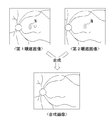
第2のアーチファクト抑制処理では、撮影光学系の光軸と被検眼の視軸との位置関係を切換えて眼底画像が少なくとも2回撮影される。更に、少なくとも2回の撮影によって得られた複数枚の眼底画像が画像処理部によって合成される。その結果として、装置は、アーチファクトが抑制された眼底画像である合成画像を取得する(図5参照)。なお、図5〜図10において、アーチファクトを符号N,又は、符号N1,N2で示す。画像処理部は、複数枚の眼底画像のうち少なくとも1枚(第1眼底画像という)におけるアーチファクトを含む領域を、その領域と眼底組織に対する位置関係が同じ画像領域であって,他の眼底画像の画像領域を用いて補完することで、合成画像を生成する。より詳細には、複数枚の眼底画像のうち少なくとも1枚におけるアーチファクトを含む領域を、他の画像において対応する画像領域で置き換えてもよい。また、複数枚の眼底画像の画像加算によって、アーチファクトを含む領域が補完されてもよい。
<Second artifact suppression processing>
In the second artifact suppression processing, the fundus image is photographed at least twice by switching the positional relationship between the optical axis of the photographing optical system and the visual axis of the subject's eye. Further, a plurality of fundus images obtained by at least two shootings are combined by the image processing unit. As a result, the device acquires a composite image that is a fundus image in which artifacts are suppressed (see FIG. 5). In FIGS. 5 to 10, artifacts are indicated by reference numeral N or reference numerals N1 and N2. The image processing unit is configured to convert an area including an artifact in at least one of the plurality of fundus images (referred to as a first fundus image) into an image area having the same positional relationship with respect to the fundus tissue and the other fundus image. A complementary image is generated by performing complementation using the image area. More specifically, a region including an artifact in at least one of a plurality of fundus images may be replaced with a corresponding image region in another image. Further, an area including an artifact may be complemented by image addition of a plurality of fundus images.
第2のアーチファクト抑制処理を実行するために、眼底撮影装置は、位置調整部を有していてもよい。位置調整部は、撮影光学系の光軸と被検眼の視軸との位置関係を変更することによって、眼底画像における眼底組織に対してアーチファクトの発生位置を調整する。位置調整部は、固視光学系を含んでいてもよい。固視光学系は、被検眼に固視標を呈示する。固視光学系は、撮影光学系の光軸と交差する方向に関し、固視標の呈示位置を複数の位置に切換え可能であってもよい。また、位置調整部は、撮影光学系を被検眼に対して移動させる駆動部を含んでいてもよい。例えば、駆動部は、被検眼の前眼部を中心として撮影光学系を旋回させることによって、撮影光学系の光軸と被検眼の視軸との位置関係を変更してもよい。勿論、位置調整部は、固視光学系と駆動部との両方を含んでもよい。 In order to execute the second artifact suppression processing, the fundus imaging apparatus may include a position adjustment unit. The position adjustment unit adjusts an occurrence position of an artifact with respect to a fundus tissue in a fundus image by changing a positional relationship between an optical axis of an imaging optical system and a visual axis of an eye to be inspected. The position adjustment unit may include a fixation optical system. The fixation optical system presents a fixation target to the eye to be examined. The fixation optical system may be capable of switching the presentation position of the fixation target to a plurality of positions in a direction intersecting the optical axis of the imaging optical system. In addition, the position adjustment unit may include a driving unit that moves the imaging optical system with respect to the eye to be inspected. For example, the driving unit may change the positional relationship between the optical axis of the imaging optical system and the visual axis of the eye by rotating the imaging optical system around the anterior segment of the eye. Of course, the position adjustment unit may include both the fixation optical system and the drive unit.
第2のアーチファクト抑制処理に関するより詳細な内容については、例えば、本出願人による特開特開2017−184787号公報等を参照されたい。 For more detailed contents regarding the second artifact suppression processing, refer to, for example, Japanese Patent Application Laid-Open No. 2017-184787 by the present applicant.
<第3のアーチファクト抑制処理>
第3のアーチファクト抑制処理では、眼底画像と背景画像とに基づく背景差分が、画像処理部によって実行され、その結果として、アーチファクトが抑制された眼底画像が生成される(図6参照)。ここでいう背景画像は、眼底画像に対する背景画像であって、少なくとも対物レンズによるアーチファクトを含んでいる。背景画像は、対物レンズの前面側を、レンズカバーなどで蓋した状態で撮影された画像であってもよい。
<Third artifact suppression processing>
In the third artifact suppression process, a background difference based on the fundus image and the background image is executed by the image processing unit, and as a result, a fundus image in which artifacts are suppressed is generated (see FIG. 6). The background image referred to here is a background image for the fundus image, and includes at least an artifact due to the objective lens. The background image may be an image captured with the front side of the objective lens covered with a lens cover or the like.
第3のアーチファクト抑制処理に関するより詳細な内容については、例えば、本出願人による特開2017−217076号公報等を参照されたい。 For more details regarding the third artifact suppression processing, refer to, for example, Japanese Patent Application Laid-Open No. 2017-217076 by the present applicant.
<第4,第5のアーチファクト抑制処理の前提となる装置構成>
第4,第5のアーチファクト抑制処理は、いずれも撮影光学系が以下のような構成であることを前提とする。即ち、撮影光学系は、スリットスキャン型の光学系である。例えば、図2に示す光学系であってもよい。撮影光学系は、スリット形成部、走査部、および、投受光分離部、を少なくとも有する。追加的に、撮影光学系は、光源、撮像素子、および、光路分岐部等を有していてもよい。
<Apparatus Configuration as Premise of Fourth and Fifth Artifact Suppression Processing>
All of the fourth and fifth artifact suppression processes are based on the premise that the imaging optical system has the following configuration. That is, the photographing optical system is a slit scan type optical system. For example, the optical system shown in FIG. 2 may be used. The imaging optical system has at least a slit forming unit, a scanning unit, and a light emitting / receiving unit. In addition, the imaging optical system may include a light source, an image sensor, an optical path branching unit, and the like.
スリット形成部は、被検眼の眼底上で照明光をスリット状に形成する。スリット形成部は、例えば、スリット状の透光部(例えば、開口)が、眼底と共役な面内に配置されたものであってもよい。 The slit forming unit forms the illumination light in a slit shape on the fundus of the eye to be inspected. The slit forming portion may be, for example, a slit-shaped light transmitting portion (for example, an opening) arranged in a plane conjugate with the fundus.
走査部は、眼底上でスリット状に形成された照明光を、スリットに対して交差する方向へ走査する。図2,図7に示すように、走査部は、スリット状に形成された照明光を、眼底上で、スリットと交差する方向(詳細には、スリットの長手方向と交差する方向)に走査する。走査部は、スリット形成部をスリットと交差する方向に移動させることによって、照明光を走査するものであってもよい。この種の走査部としては、メカニカルシャッター、液晶シャッター、オプティカルチョッパー、および、ドラムリール等が例示される。 The scanning unit scans the illumination light formed in a slit shape on the fundus in a direction intersecting the slit. As shown in FIGS. 2 and 7, the scanning unit scans the illumination light formed in a slit shape on the fundus in a direction intersecting the slit (specifically, a direction intersecting the longitudinal direction of the slit). . The scanning unit may scan the illumination light by moving the slit forming unit in a direction intersecting the slit. Examples of this type of scanning unit include a mechanical shutter, a liquid crystal shutter, an optical chopper, and a drum reel.
スリットの走査方向は、好ましくは、スリットと直交する方向である。但し、スリットの直交方向に対して斜め方向であってもよい。 The scanning direction of the slit is preferably a direction orthogonal to the slit. However, the direction may be oblique to the direction orthogonal to the slit.
また、走査部は、スリット形成部を通過した光の向きを、変化させる部材であってもよい。例えば、ガルバノスキャナ等の各種の光スキャナが、走査部として利用されてもよい。光を旋回させて走査を行うタイプの走査部は、被検眼の瞳と共役な位置に置かれてもよい。 Further, the scanning unit may be a member that changes the direction of light passing through the slit forming unit. For example, various optical scanners such as a galvano scanner may be used as the scanning unit. A scanning unit of a type that scans by rotating light may be placed at a position conjugate with the pupil of the eye to be examined.
撮影光学系は、更に、光路結合部、および、対物レンズを有していてもよい。 The imaging optical system may further include an optical path coupling unit and an objective lens.
光路結合部は、照明光の投光光路と眼底反射光の受光光路とを結合および分離する。光路結合部によって形成される、投光光路と受光光路との共通光路上に、対物レンズは配置される。このとき、撮影光学系の光軸(以下、「撮影光軸」ともいう)と、対物レンズの光軸とが一致していることが望ましい。 The optical path coupling unit couples and separates the projection optical path of the illumination light and the light reception optical path of the fundus reflection light. The objective lens is arranged on a common optical path formed by the optical path coupling section and the light transmitting optical path and the light receiving optical path. At this time, it is desirable that the optical axis of the photographing optical system (hereinafter, also referred to as “photographing optical axis”) coincides with the optical axis of the objective lens.
各種のビームスプリッターを、光路結合部として利用できる。この場合、光路結合部は、穴開きミラーであってもよいし、単なるミラーであってもよいし、ハーフミラーであってもよいし、その他のビームスプリッターであってもよい。 Various beam splitters can be used as the optical path coupling unit. In this case, the optical path coupling unit may be a perforated mirror, a simple mirror, a half mirror, or another beam splitter.
投受光分離部は、被検眼の瞳上において、照明光が投光される区域(投光領域)と、照明光による眼底反射光が取り出される区域(受光領域)と、を分離する。 The light projection / reception separating unit separates, on the pupil of the subject's eye, an area where the illumination light is projected (light projection area) and an area where the fundus reflection light by the illumination light is extracted (light reception area).
詳細には、図2,図8に示すように、投受光分離部によって、投光領域が、照明光の走査方向に関して互いに分離した2つの位置に形成される。2つの投光領域は、撮影光軸を挟むように形成されてもよい。なお、第1実施形態において、投受光分離部は、投光領域を少なくとも2つ形成するものであればよく、3つ以上の投光領域を形成するものであってもよい。各々の投光領域を通過した照明光は、眼底上で、同一のスリット状領域を照射する。そして、走査部の駆動に伴い、スリット状の領域が走査される。 Specifically, as shown in FIGS. 2 and 8, the light projecting / receiving part forms two light projecting regions separated from each other in the scanning direction of the illumination light. The two light projecting regions may be formed so as to sandwich the photographing optical axis. In the first embodiment, the light-projecting / receiving separation unit may be one that forms at least two light-projecting regions, and may be one that forms three or more light-projecting regions. The illumination light that has passed through each light projecting area illuminates the same slit-shaped area on the fundus. Then, as the scanning unit is driven, the slit-shaped area is scanned.
図8に示すように、投受光分離部によって、受光領域が、2つの投光領域に挟まれるように形成される。つまり、一方の投光領域、受光領域、他方の投光領域、の順に、各領域が一列に並んで形成される。また、受光領域は、撮影光軸上に形成されてもよい。投光領域と受光領域とは、互いに重なり合わないように配置されてもよい。その場合、角膜や中間透光体で、照明光の一部が反射および散乱を起こし、眼底画像にフレアーを生じさせることが軽減される。 As shown in FIG. 8, the light receiving / receiving section is formed so as to be sandwiched between the two light emitting areas by the light emitting / receiving section. That is, the regions are formed in a line in the order of one light emitting region, light receiving region, and the other light emitting region. Further, the light receiving region may be formed on the photographing optical axis. The light emitting area and the light receiving area may be arranged so as not to overlap each other. In that case, it is reduced that a part of the illumination light is reflected and scattered in the cornea and the intermediate light transmitting body, and flare is generated in the fundus image.
投受光分離部は、照明光の投光光路、および、受光光路にそれぞれ配置される複数の部材を含んでいてもよい。 The light projection / reception separation unit may include a plurality of members arranged on the light projection light path of the illumination light and the light reception light path, respectively.
投受光分離部は、その一部が、例えば、照明光の投光光路における瞳共役面上において、照明光の走査方向に関して互いに離れた少なくとも2つの位置に照明光の照射位置を設定するものであってもよい。この場合、2つの照射位置に、照明光を発する光源がそれぞれ配置されてもよいし、2つの照射位置に、照明光を通過させる開口がそれぞれ配置されてもよい。 The light-projection / light-receiving separation unit partially sets the irradiation position of the illumination light at at least two positions separated from each other with respect to the scanning direction of the illumination light, for example, on a pupil conjugate plane in the light-projecting optical path of the illumination light. There may be. In this case, a light source that emits illumination light may be disposed at each of the two irradiation positions, and an opening that allows illumination light to pass therethrough may be disposed at each of the two irradiation positions.
換言すれば、投受光分離部は、被検眼の瞳と共役な位置において走査方向に関して互いに異なる位置に配置される、2つの照明光源、または、2つの見かけ上の照明光源を、少なくとも含むものであってもよい。これにより、投光領域は、照明光の走査方向に関して互いに分離した2つの位置に形成される。より好ましくは、2つの照明光源、または、2つの見かけ上の照明光源は、撮影光軸に対して対称に配置されてもよい。これにより、2つの投光領域を、撮影光軸に関して対称に形成できる。2つの光源、または、2つの見かけ上の光源からの投光状態は、後述の制御部によって、光源毎に制御可能であってもよい。投光状態が光源毎に制御される結果として、照明光を通過させるか否かが、各々の投光領域に対して個別に設定される。勿論、投受光分離部は、3つ以上の照明光源、または、3つ以上の見かけ上の照明光源を含むものであってもよい。 In other words, the light projection / reception separation unit includes at least two illumination light sources or two apparent illumination light sources that are arranged at positions different from each other in the scanning direction at a position conjugate with the pupil of the subject's eye. There may be. As a result, the light projection area is formed at two positions separated from each other in the scanning direction of the illumination light. More preferably, the two illumination light sources, or the two apparent illumination light sources, may be arranged symmetrically with respect to the imaging optical axis. Thereby, two light projection areas can be formed symmetrically with respect to the photographing optical axis. The state of light emission from two light sources or two apparent light sources may be controllable for each light source by a control unit described later. As a result of controlling the light projection state for each light source, whether or not to transmit the illumination light is individually set for each light projection area. Of course, the light projecting / receiving separation unit may include three or more illumination light sources, or three or more apparent illumination light sources.
なお、投光状態としては、光源または見かけ上の光源からの照明光が被検眼に到達する状態と、到達しない状態と、の2種類の状態が少なくともあり得る。投光状態の切換は、光源の点灯制御によって実現されてもよい。また、光源、又は、見かけ上の光源から被検眼へ向かう光束を選択的に遮ぎるシャッターを駆動制御することによって、投光状態が切換えられてもよい。 Note that the light projection state may include at least two types of states: a state in which illumination light from a light source or an apparent light source reaches the subject's eye and a state in which illumination light does not reach the eye. The switching of the projection state may be realized by controlling the lighting of the light source. The light projection state may be switched by driving and controlling a light source or a shutter that selectively blocks a light beam from the apparent light source toward the subject's eye.
また、投受光分離部は、その一部が、照明光の受光光路における瞳共役面上において、2つの投光領域に挟まれる領域である受光領域からの眼底反射光を撮像面側へ通過させ、それ以外の光を撮像面側へ通過させなくするものであってもよい。例えば、投受光分離部は、受光領域からの眼底反射光を撮像面側へ通過させ、それ以外の光を遮光する遮光部材を含むものであってもよい。遮光部材は、例えば、受光光路において瞳共役面上に配置されてもよい。例えば、遮光部材として、撮影光軸を中心に開口を有する絞りが設けられた場合、絞りの開口像によって、受光領域が形成される。 In addition, the light-projecting / receiving separation unit partially passes the fundus reflection light from the light-receiving area, which is an area sandwiched between the two light-projecting areas, on the pupil conjugate plane in the light-receiving optical path of the illumination light to the imaging surface side. Alternatively, other light may be prevented from passing through to the imaging surface side. For example, the light projection / reception separation unit may include a light blocking member that allows the fundus reflection light from the light reception area to pass to the imaging surface side and blocks other light. The light blocking member may be arranged on the pupil conjugate plane in the light receiving optical path, for example. For example, when a stop having an opening centered on the photographing optical axis is provided as a light blocking member, a light receiving region is formed by an opening image of the stop.
投受光分離部に遮光部材が含まれる場合、遮光部材は、前述の光路結合部と共用されていてもよいし、別体であってもよい。 When a light-shielding member is included in the light-projecting / receiving separation unit, the light-shielding member may be shared with the above-described optical path coupling unit or may be a separate unit.
<第4のアーチファクト抑制処理>
上記の装置構成において、制御部は、照明光を通過させるか否かを、被検眼の瞳上の2つの投光領域に対して個別に設定してもよい。この場合、制御部は、2つの投光領域の一方(いずれか)から選択的に投光された照明光に基づいて、眼底画像を撮影してもよい。
<Fourth artifact suppression processing>
In the above-described apparatus configuration, the control unit may individually set whether or not to transmit the illumination light for the two light-projection regions on the pupil of the subject's eye. In this case, the control unit may capture a fundus image based on the illumination light selectively projected from one (any one) of the two projection areas.
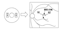
ところで、眼底画像における撮影光軸の近傍位置には、対物レンズのレンズ面の中心部で照明光が反射されることによる、反射像(輝点像、アーチファクトの一種)が生じる場合がある。投光領域は撮影光軸から離れていることから、反射像は、眼底画像における撮影光軸の位置からややズレた位置に出現しやすい。一例として、2つの投光領域の両方から照明光を同時に投光して撮影した眼底画像を、図9Aに示す。図9Aに示すように、2つの投光領域に対応して、眼底画像の画像中心部において、撮影光軸を挟んだ2箇所で、反射像(符号N1,N2で示す)が生じ得る。2つの反射像は、走査方向に並んで(つまり、走査方向に関して異なる位置に)出現する。 By the way, in the vicinity of the photographing optical axis in the fundus image, a reflected image (a kind of bright spot image or a kind of artifact) may be generated due to the reflection of the illumination light at the center of the lens surface of the objective lens. Since the light projection area is far from the photographing optical axis, the reflected image is likely to appear at a position slightly deviated from the position of the photographing optical axis in the fundus image. As an example, FIG. 9A shows a fundus image captured by simultaneously projecting illumination light from both of the two projection areas. As shown in FIG. 9A, corresponding to the two light projecting regions, reflected images (indicated by reference numerals N1 and N2) may be generated at two places across the photographing optical axis in the central portion of the fundus image. The two reflection images appear side by side in the scanning direction (that is, at different positions in the scanning direction).
これに対し、本実施形態では、2つの投光領域のうち一方から選択的に照明光を眼底へ投光して、眼底画像が撮影される。これによって、対物レンズにおいて、反射像を生じさせる箇所が上記の場合に対して半減される。その結果として、図9Bに示すように、眼底画像における反射像を半減できる。このように、被検眼の瞳上における2つの投光領域のうち、一方から選択的に照明光を眼底へ投光して、眼底画像を撮影することは、アーチファクトを軽減するうえで、有利である。 In contrast, in the present embodiment, the illumination light is selectively projected from one of the two projection areas to the fundus, and a fundus image is captured. As a result, the position of the objective lens where a reflected image is generated is reduced by half compared to the above case. As a result, as shown in FIG. 9B, the reflection image in the fundus image can be reduced by half. As described above, selectively projecting the illumination light from one of the two light projecting regions on the pupil of the subject's eye to the fundus and photographing the fundus image is advantageous in reducing artifacts. is there.
<第5のアーチファクト抑制処理>
制御部は、2つの投光領域のうち一方から選択的に照明光を眼底へ投光して1枚目の眼底画像を撮影した後、更に、照明光が投光される投光領域を他方へ切換え、他方から選択的に照明光を投光して2枚目の眼底画像を撮影してもよい。このような2回の撮影によって、対物レンズによる反射像等のアーチファクトの出現位置が、撮影に利用した投光領域に応じて互いに異なる、2枚の眼底画像が得られる。1回目の撮影と2回目の撮影の間で、被検眼と撮影光学系との位置関係を変化させずに撮影が行われてもよい。また、2枚目の眼底画像の撮影は、1枚目の眼底画像の撮影から連続的に、且つ、自動的に実行されることが望ましい。
<Fifth Artifact Suppression Processing>
The control unit selectively emits illumination light to the fundus from one of the two light projection areas to capture the first fundus image, and further sets the light emission area where the illumination light is projected to the other. To the second fundus image by selectively projecting illumination light from the other side. By performing such two shootings, two fundus images are obtained in which the appearance positions of artifacts such as a reflection image by the objective lens are different from each other depending on the projection area used for the shooting. The imaging may be performed between the first imaging and the second imaging without changing the positional relationship between the subject's eye and the imaging optical system. Further, it is desirable that the photographing of the second fundus image be performed continuously and automatically from the photographing of the first fundus image.
本実施形態では、2枚の眼底画像を撮影する際に、被検眼と撮影光学系との位置関係を変化させる必要が無く、しかも、光源の点灯切換、あるいは、シャッターの駆動等により、比較的短時間で、被検眼の瞳上における投光領域を切換えできる。よって、2枚の眼底画像が短時間で撮影可能である。結果、1枚目の眼底画像と2枚目の眼底画像とを連続的に撮影しても、被検者の負担が抑制される。また、照明光が可視光であったとしても、1枚目の撮影後、速やかに2枚目の撮影が行われるので、1枚目の撮影に起因する縮瞳が2枚目の撮影において与える影響を抑制できる。 In the present embodiment, when two fundus images are taken, there is no need to change the positional relationship between the subject's eye and the imaging optical system, and the light source is switched on or off, or the shutter is driven. The light projection area on the pupil of the subject's eye can be switched in a short time. Therefore, two fundus images can be captured in a short time. As a result, even if the first fundus image and the second fundus image are continuously photographed, the burden on the subject is suppressed. Even if the illumination light is visible light, the second image is taken immediately after the first image is taken, so that the miosis caused by the first image is given in the second image. The effect can be suppressed.
ここで、縮瞳の影響としては、照明光および眼底反射光が虹彩でケラレることで、眼底画像が暗くなること等が例示される。画像中心部と画像周辺部との間におけるケラレの影響(明るさの変化)は、必ずしも一様ではない。例えば、画像の周辺部では、撮影画角が大きくなるほどケラレの影響を受けやすくなることがあり得る。 Here, examples of the effect of the miosis include that the illumination light and the fundus reflection light are vignetted by the iris, thereby darkening the fundus image. The effect of vignetting (change in brightness) between the center of the image and the periphery of the image is not always uniform. For example, the periphery of an image may be more susceptible to vignetting as the shooting angle of view increases.
第5のアーチファクト抑制処理では、これらの2枚の眼底画像を合成処理することによって、1枚の眼底画像(以下、「合成画像」と称する)を生成してもよい。合成処理は、画像処理部によって実行される。本実施形態では、アーチファクトの影響が抑制された画像を得るために、合成処理が行われる。合成手法には、以下に例示するように、種々の手法がありうる。 In the fifth artifact suppression process, a single fundus image (hereinafter, referred to as a “combined image”) may be generated by performing a combining process on these two fundus images. The combining process is performed by the image processing unit. In the present embodiment, a combining process is performed to obtain an image in which the influence of the artifact is suppressed. There are various synthesis methods as exemplified below.
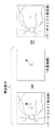
例えば、2枚の眼底画像のうち、一方の眼底画像におけるアーチファクトを含む領域を、その領域と対応する他方の眼底画像の一部と置き換えることで、合成画像が生成されてもよい(図10参照)。このとき、走査線単位で置き換えが行われてもよい。例えば、アーチファクトとして前述の反射像が生じる場合、一方の眼底画像の画像中心部に生じる反射像を、他方の眼底画像において対応する領域と置き換えられることで、合成画像が生成されてもよい。 For example, a composite image may be generated by replacing a region including an artifact in one fundus image of two fundus images with a part of the other fundus image corresponding to the region (see FIG. 10). ). At this time, replacement may be performed in units of scanning lines. For example, when the above-described reflection image occurs as an artifact, a composite image may be generated by replacing a reflection image generated at the image center of one fundus image with a corresponding region in the other fundus image.
また、2枚の眼底画像の加算平均画像として、合成画像を生成してもよい。この場合、反射像と、それ以外の領域との間で、異なる加算比率を与えて加算平均処理が行われてもよい。 Further, a composite image may be generated as an average image of two fundus images. In this case, the averaging process may be performed by giving different addition ratios between the reflection image and the other regions.
なお、反射像が生じる領域は、視度によって多少の変動はあるものの、撮影光軸を基準とする略一定の範囲となる。このため、2枚の眼底画像において、合成処理で他方の画像と合成される領域は、予め定められていてもよい。但し、必ずしもこれに限られるものではなく、眼底画像に対して反射像の検出処理を行い、検出処理の結果に基づいて、合成される領域を個別に設定してもよい。また、視度に応じて合成される領域が設定されてもよい。 The area where the reflection image occurs is a substantially constant range based on the photographing optical axis although there is some variation depending on the diopter. For this reason, in the two fundus images, the region to be combined with the other image in the combining process may be determined in advance. However, the present invention is not limited to this, and the detection processing of the reflection image may be performed on the fundus image, and the regions to be combined may be individually set based on the result of the detection processing. Further, an area to be combined may be set according to the diopter.
なお、制御部は、合成画像と対応する走査範囲の一部のみの走査に基づいて1枚目の眼底画像を撮影し、投光領域を切換えたうえで、残り一部の走査に基づいて2枚目の眼底画像を撮影し、各眼底画像を合成(コラージュ)することで、合成画像を生成してもよい。この場合、走査範囲は、撮影光軸を中心として2分割され、分割された2つの走査範囲において、それぞれ眼底画像を撮影することが好ましい。なお、この場合、合成処理は、必ずしも画像処理に限定されるものでは無い。例えば、照明光が、走査範囲の分割位置に到来したタイミングで、照明光を投光させる投光領域を切換えることで、撮像面上に、合成画像を形成できる。 In addition, the control unit captures the first fundus image based on scanning of only a part of the scanning range corresponding to the composite image, switches the light projection area, and then performs control based on the remaining part of the scanning. A composite image may be generated by taking a second fundus image and combining (collage) the fundus images. In this case, it is preferable that the scanning range is divided into two around the photographing optical axis, and a fundus image is photographed in each of the two divided scanning ranges. Note that, in this case, the synthesis processing is not necessarily limited to image processing. For example, a composite image can be formed on the imaging surface by switching the projection area where the illumination light is projected at the timing when the illumination light arrives at the division position of the scanning range.
この場合において、2枚の眼底画像の間で、眼底上の走査範囲と照明光が投光される投光領域との関係は、2枚の眼底画像の間で交差していることが好ましい。例えば、2つの投光領域が上下方向に並べて配置されると共に、眼底上で照明光が上下方向に走査される場合、上側の投光領域から照明光を通過させるときは、眼底の下半分の走査に基づいて1枚目の眼底画像を撮影し、下側の投光領域から照明光を通過させるときは、眼底の上半分の走査に基づいて2枚目の眼底画像を撮影し、両者から合成画像を生成してもよい。この場合、各々の投光領域との関係で、対物レンズの反射像、および、フレアー等のアーチファクトが含まれ難い部分を撮影した画像同士が合成される。従って、アーチファクトが抑制された合成画像を得ることができる。 In this case, between the two fundus images, it is preferable that the relationship between the scanning range on the fundus and the projection area where the illumination light is projected intersects between the two fundus images. For example, when the two light projecting regions are arranged side by side in the vertical direction, and the illumination light is scanned on the fundus in the vertical direction, when passing the illumination light from the upper light projecting region, the lower half of the fundus is used. When the first fundus image is photographed based on the scanning, and the illumination light is allowed to pass from the lower light projecting area, the second fundus image is photographed based on the scanning of the upper half of the fundus. A composite image may be generated. In this case, in relation to each projection area, the reflected image of the objective lens and the images obtained by photographing the portion where the artifact such as flare is hardly included are combined. Therefore, it is possible to obtain a composite image in which artifacts are suppressed.
この合成処理に代えて、次のような撮影制御が実行されてもよい。即ち、撮影時に眼底上を走査する照明光が、2分割の境界位置に到来したタイミングで、投光領域が制御部によって切換えられてもよい。合成処理を必要とせずに、反射像が抑制された合成画像が生成される。 The following shooting control may be executed instead of the synthesis processing. That is, the projection area may be switched by the control unit at the timing when the illumination light that scans on the fundus at the time of photographing reaches the boundary position of the two divisions. A composite image in which a reflection image is suppressed is generated without requiring a composite process.
「実施例」
次に、図1〜図4,図11,および、図12を参照して、第1実施形態及び第2実施形態に係る眼底撮影装置の実施例を示す。
"Example"
Next, an example of the fundus imaging apparatus according to the first embodiment and the second embodiment will be described with reference to FIGS. 1 to 4, 11, and 12.
眼底撮影装置1(以下、単に、「撮影装置1」と省略する)は、被検眼の眼底上で照明光をスリット状に形成し、眼底上でスリット状に形成された領域を走査し、照明光の眼底反射光を受光することで、眼底の正面画像を撮影する。 The fundus imaging apparatus 1 (hereinafter, simply referred to as “imaging apparatus 1”) forms illumination light in a slit shape on the fundus of the eye to be inspected, scans the slit-shaped area on the fundus, and illuminates. A front image of the fundus is captured by receiving light reflected by the fundus.
<装置の外観>
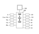
図1を参照して、撮影装置1の外観構成を説明する。撮影装置1は、撮影ユニット3を有する。撮影ユニット3は、図2で示す光学系を主に備える。撮影装置1は、基台7、駆動部8、顔支持ユニット9、および、顔撮影カメラ110を有し、これらを用いて、被検眼Eと撮影ユニット3との位置関係を調整する。
<Appearance>
With reference to FIG. 1, an external configuration of the photographing apparatus 1 will be described. The photographing device 1 has a photographing
駆動部8は、基台7に対して左右方向(X方向)及び前後方向(Z方向であり、換言すれば、作動距離方向)に移動できる。また、駆動部8は、更に、撮影ユニット3を、駆動部8上で被検眼Eに対して3次元方向に移動させる。駆動部8には、予め定められた各可動方向に駆動部8または撮影ユニット3を移動させるためのアクチュエータを有しており、制御部80からの制御信号に基づいて駆動される。顔支持ユニット9は、被検者の顔を支持する。顔支持ユニット9は基台7に固定されている。
The
顔撮影カメラ110は、撮影ユニット3に対する位置関係が一定となるように、筐体6に固定されている。顔撮影カメラ110は、被検者の顔を撮影する。制御部100は、撮影された顔画像から被検眼Eの位置を特定し、駆動部8を駆動制御することで、特定した被検眼Eの位置に対して撮影ユニット3を位置合わせする。
The
また、撮影装置1は、モニタ120を更に有している。モニタ120には、眼底観察像、眼底撮影像、前眼部観察像等が表示される。
Further, the imaging device 1 further includes a
<実施例の光学系>
次に、図2を参照して、撮影装置1の光学系を説明する。撮影装置1は、撮影光学系(眼底撮影光学系)10と、前眼部観察光学系40と、を有している。これらの光学系は、撮影ユニット3に設けられている。
<Optical System of Example>
Next, an optical system of the photographing apparatus 1 will be described with reference to FIG. The imaging device 1 includes an imaging optical system (fundus imaging optical system) 10 and an anterior ocular segment observation
図2において、被検眼の瞳と共役な位置には撮影光軸上に『△』を、眼底共役位置には撮影光軸上に『×』を付して、それぞれ示す。 In FIG. 2, a position conjugate to the pupil of the subject's eye is indicated by “△” on the imaging optical axis, and a fundus conjugate position is indicated by “×” on the imaging optical axis.
撮影光学系10は、照射光学系10aと、受光光学系10bと、を有する。実施例において、照射光学系10aは、光源ユニット11、レンズ13、スリット状部材15a、レンズ17a,17、ミラー18、穴開きミラー20、および、対物レンズ22を有する。受光光学系10bは、対物レンズ22、穴開きミラー20、レンズ25a,25b、スリット状部材15b、および、撮像素子28を有する。なお、穴開きミラー20は、照射光学系10aと受光光学系10bとの光路を結合する光路結合部である。穴開きミラー20は、光源からの照明光を、被検眼E側へ反射し、被検眼Eからの眼底反射光のうち、開口を通過した一部を、撮像素子側へ通過させる。穴開きミラー20以外の種々のビームスプリッターを用いることができる。例えば、穴開きミラー20に代えて、穴開きミラー20と透光部と反射部が逆転したミラーが光路結合部として用いられてもよい。但し、この場合、ミラーの反射側に受光光学系10bの独立光路が置かれ、ミラーの透過側に照射光学系10aの独立光路が置かれる。また、穴開きミラー、および、その代替手段としてのミラーは、それぞれ、ハーフミラーと遮光部との組み合わせに、更に置き換えることができる。
The photographing
本実施例において、光源ユニット11は、波長帯が異なる複数種類の光源を有している。例えば、光源ユニット11は、可視光源11a,11bと、赤外光源11c,11dとを有する。このように、本実施例の光源ユニット11には、波長毎に光源が2つずつ設けられている。同じ波長の2つの光源は、瞳共役面上において、撮影光軸Lから離れて配置される。2つの光源は、図2における走査方向であるX方向に沿って並べられており、撮影光軸Lに関して軸対称に配置される。図2に示すように、2つの光源の外周形状は、走査方向に比べて、走査方向と交差する方向が長い矩形形状であってもよい。
In this embodiment, the
2つの光源からの光は、レンズ13を通過して、スリット状部材15に照射される。本実施例において、スリット状部材15aは、Y方向に沿って細長く形成された透光部(開口)を持つ。これにより、眼底共役面において、照明光がスリット状に形成される(眼底上でスリット状に照明された領域を、符号Bとして図示する)。
Light from the two light sources passes through the
図2において、スリット状部材15aは、透光部が撮影光軸LをX方向に横切るようにして、駆動部15cによって変位される。これにより、本実施例における照明光の走査が実現される。なお、本実施例では、受光系側でも、スリット状部材15bによる走査が行われる。本実施例では、投光側と受光側のスリット状部材は、1つの駆動部(アクチュエータ)によって、連動して駆動される。
In FIG. 2, the slit-shaped
照射光学系10aでは、各光源の像が、レンズ13から対物レンズ22までの光学系によってリレーされて、瞳共役面上で結像される。つまり、瞳共役面上において、走査方向に関して分離した位置に、2つの光源の像が形成される。このようにして、本実施例では、瞳共役面上における2つの投光領域P1,P2は、2つの光源の像として形成される。
In the irradiation
また、スリット状部材15aを通過したスリット状の光は、レンズ17aから対物レンズ22までの光学系によってリレーされて、眼底Er上に結像する。これにより、眼底Er上で照明光がスリット状に形成される。照明光は、眼底Er上で反射され、瞳孔Epから取り出される。
The slit-shaped light passing through the slit-shaped
ここで、穴開きミラー20の開口は、被検眼の瞳と共役なので、眼底画像の撮影に利用される眼底反射光は、被検眼の瞳上において穴開きミラー開口の像(瞳像)を通過する一部に制限される。このように、被検眼の瞳上における開口の像が、本実施例における受光領域Rとなる。受光領域Rは、2つの投光領域P1,P2(2つの光源の像)に挟まれて形成される。また、各像の結像倍率、開口の径、2つの光源の配置間隔が適宜設定された結果として、受光領域Rと、2つの投光領域P1,P2とは、瞳上において互いに重ならないように形成される。これにより、フレアーの発生が良好に軽減される。
Here, since the aperture of the
対物レンズ22および穴開きミラー20の開口を通過した眼底反射光は、レンズ25a,25bを介して、眼底共役位置に、眼底Erのスリット状領域を結像する。このとき、結像の位置にスリット状部材15bの透光部が配置されていることで、有害光が除去される。
The fundus reflection light passing through the
撮像素子28は、眼底共役位置に配置されている。本実施例では、スリット状部材15bと撮像素子28の間にリレー系27が設けられており、これにより、スリット状部材15bと撮像素子28との双方が、眼底共役位置で配置される。その結果、有害光の除去と、結像との両方が、良好に行われる。これに代えて、撮像素子28とスリット状部材15bとの間のリレー系27を省略し、両者を近接配置してもよい。本実施例では、撮像素子28として、2次元的な受光面を持つデバイスが用いられている。例えば、CMOS、二次元CCD等であってもよい。撮像素子28には、スリット状部材15bの透光部で結像した、眼底Erのスリット状領域の像が投影される。撮像素子28は、赤外光および可視光の両方に感度を持つ。
The
本実施例では、スリット状の照明光が眼底Er上で走査されるに従って、撮像素子28の走査線毎に、眼底Er上の走査位置の像(スリット状の像)が順次投影される。このように、撮像素子には、時分割で走査範囲の全体像が投影される。結果として、走査範囲の全体像として、眼底Erの正面画像が撮像される。
In this embodiment, as the slit-shaped illumination light is scanned on the fundus Er, an image (slit-shaped image) of the scanning position on the fundus Er is sequentially projected for each scanning line of the
なお、実施例において受光系における走査部は、メカニカルにスリットを走査するデバイスであったが、必ずしもこれに限定されるものではない。例えば、受光光学系側の走査部は、電子的にスリットを走査するデバイスであってもよい。一例として、撮像素子28がCMOSである場合、CMOSのローリングシャッター機能によって、スリットの走査が実現されてもよい。この場合、撮像面上で露光される領域を、投光系における走査部と同期して変位させることで、有害光を除去しつつ、効率良く撮影できる。また、液晶シャッター等を、電子的にスリットを走査する走査部として用いることもできる。
In the embodiment, the scanning unit in the light receiving system is a device for mechanically scanning the slit, but is not necessarily limited to this. For example, the scanning unit on the light receiving optical system side may be a device that electronically scans the slit. As an example, when the
撮影光学系10は、視度補正部を有している。本実施例では、照射光学系10aの独立光路、受光光学系10bの独立光路、のそれぞれに視度補正部(視度補正光学系17,25)が設けられている。以下では、便宜上、照射側の視度補正光学系を照射側視度補正光学系17と称し、受光側の視度補正光学系を受光側視度補正光学系25と称する。本実施例の照射側視度補正光学系17は、レンズ17a,レンズ17bおよび駆動部17c(図3参照)を含む。また、本実施例の受光側視度補正光学系25は、レンズ25a、レンズ25b、および、駆動部25c(図3参照)を含む。照射側視度補正光学系17においてはレンズ17aとレンズ17bとの間隔が、受光側視度補正光学系25においては、レンズ25aとレンズ25bとの間隔が変更される。これにより照射光学系10aと受光光学系10bとの各々において視度補正が行われる。
The imaging
照射光学系10aの駆動部17cと、受光光学系10bの駆動部25cとは、独立に駆動可能である。その結果、本実施例では、図4Bに示すように、照射光学系10aにおける視度補正量である照射側補正量と、受光光学系10bにおける視度補正量である受光側補正量とを、それぞれ独立に設定できる。
The driving unit 17c of the irradiation
本実施例において、照射側視度補正光学系17と、受光側視度補正光学系25と、の各々は、テレセントリック光学系を含む。各々のテレセントリック光学系は、視度補正量が変化しても像側の領域における像高さを維持する。これにより、眼底上における照射光学系のスリット開口と受光光学系のスリット開口との位置関係を、照射側補正量と受光側補正量とのバランスに関わらず一定に保つことができる。このため、眼底上における照射光学系のスリット開口と受光光学系のスリット開口とを、照射側補正量と受光側補正量とのバランスに関わらず常に一致させることができる。また、視度補正量の変化に応じた画像サイズの変化を抑制できる。
In this embodiment, each of the irradiation-side diopter correction
図2に示すように、更に、撮影光学系10は、フォーカス指標投影光学系の1例として、スプリット指標投影光学系50を有する。スプリット指標投影光学系50は、2つのスプリット指標を眼底に投影する。スプリット指標は、フォーカス状態の検出に利用される。また、本実施例では、フォーカス状態の検出結果から、被検眼Eの屈折度数が取得される。
As shown in FIG. 2, the imaging
スプリット指標投影光学系50は、例えば、光源51(赤外光源)と、指標板52と、偏角プリズム53とを少なくとも有していてもよい。本実施例において、指標板52は、受光光学系50における撮像面と対応する位置へ配置されている。同様に、各々のスリット状部材15a,15bとも対応する位置へ配置される。詳細には、照射側および受光側の視度補正量が0Dである場合に、正視眼(0D眼)の眼底と略共役な位置に、視標板52は配置される。偏角プリズム53は、指標板52よりも被検眼側において、指標板52に近接して配置される。
The split index projection
指標板52は、例えば、スリット光を指標として形成する。偏角プリズム53は、視標板52を介した指標光束を分離し、スプリット指標を形成する。分離されたスプリット指標は、照射側視度補正光学系17から対物レンズ22までを介して、被検眼の眼底へ投影される。このため、スプリット指標は、眼底画像(例えば、眼底観察画像)に映り込む。
The
指標板52が眼底共役位置からズレている場合は、眼底上で2つのスプリット指標は分離しており、指標板52が眼底共役位置に配置される場合は、2つのスプリット指標は一致される。共役関係は、偏角プリズム53と被検眼Erとの間に配置される照射側視度補正光学系17によって調整される。そこで、本実施例では、照射側視度補正量と受光側視度補正量とを一致させつつデフォーカスが行われる。このとき、スプリット指標の分離状態が、フォーカス状態を示す。2つのスプリット指標が合致されるように、照射側および受光側の視度補正量が各々が調整されることによって、撮像面とスリット状部材15a,15bとの各々が、眼底と共役な位置関係となる。
When the
撮像面とスリット状部材15a,15bとの各々が眼底と共役な位置関係であるときの視度補正量から、被検眼Eの屈折度数を導くことができる。そこで、本実施例において、更に、レンズ17aとレンズ17bとの間隔、または、レンズ25aとレンズ25bとの間隔のうちいずれかを読み出すエンコーダ(図示を省略する)を有していてもよく、エンコーダからの信号に基づいて、被検眼Eの屈折度数が取得されてもよい。
The refractive power of the eye E can be derived from the diopter correction amount when each of the imaging surface and the
なお、走査部は、例えば、図11に示すようなオプティカルチョッパーであってもよい。オプティカルチョッパーは、外周に複数のスリットが形成されたホイール持ち、ホイールを回転させることで、高速にスリットをスキャンできる。 The scanning unit may be, for example, an optical chopper as shown in FIG. The optical chopper has a wheel having a plurality of slits formed on the outer periphery, and can rotate the wheel to scan the slits at high speed.
ここで、図2では、照射光学系10aの光源ユニット11からミラー18までと、受光光学系10bの穴開きミラー20から撮像素子28までとが、X方向に並列されているが、例えば、穴開きミラー20とミラー18との向きを、図示した状態から90°回転させ、両者をY方向に並列させることによって、オプティカルチョッパーを走査部として適用可能になる。この場合、ホイールの上端と下端との2箇所で、照射光学系10aの光軸と受光光学系10bの光軸とをそれぞれ横切らせることで、1体のオプティカルチョッパーで、投光系および受光系の走査を、容易に同期させることができる。
Here, in FIG. 2, the components from the
<前眼部観察光学系>
次いで、前眼部観察光学系40を説明する。前眼部観察光学系40は、対物レンズ22とダイクロイックミラー43と、を撮影光学系10と共用する。前眼部観察光学系40は、更に、光源41、ハーフミラー45、撮像素子47等を含む。撮像素子47は、二次元撮像素子であり、例えば瞳孔Epと光学的に共役な位置に配置される。前眼部観察光学系40は、赤外光で前眼部を照明し、前眼部の正面画像を撮影する。
<Anterior eye observation optical system>
Next, the anterior ocular segment observation
なお、図2に示した前眼部観察光学系40は一例に過ぎず、他の光学系とは独立した光路で前眼部を撮像してもよい。
Note that the anterior ocular segment observation
<実施例の制御系>
次に、図3を参照して、撮影装置1の制御系を説明する。本実施例では、制御部100によって、撮影装置1の各部の制御が行われる。また、便宜上、撮影装置1で得られた各種画像の画像処理についても、制御部100によって行われるものとする。換言すれば、本実施例では、制御部100が、画像処理部を兼用している。
<Control system of embodiment>
Next, a control system of the photographing apparatus 1 will be described with reference to FIG. In this embodiment, the
制御部100は、各部の制御処理と、演算処理とを行う電子回路を有する処理装置(プロセッサ)である。制御部100は、CPU(Central Processing Unit)およびメモリ等で実現される。制御部100は、記憶部101と、バス等を介して電気的に接続されている。
The
記憶部101には、各種の制御プログラムおよび固定データ等が格納される。また、記憶部101には、一時データ等が記憶されてもよい。
The
撮影装置1による撮影画像は、記憶部101に記憶されていてもよい。但し、必ずしもこれに限られるものではなく、外部の記憶装置(例えば、LANおよびWANで制御部100に接続される記憶装置)へ撮影画像が記憶されてもよい。
The image captured by the image capturing apparatus 1 may be stored in the
また、制御部100は、駆動部8、光源11a〜11d、駆動部15c、駆動部17c、駆動部25c、撮像素子28、光源41、撮像素子47、光源51、入力インターフェイス110、およびモニタ120等の各部とも電気的に接続されている。
The
また、制御部100は、入力インターフェイス110(操作入力部)から出力される操作信号に基づいて、上記の各部材を制御する。入力インターフェイス110は、検者の操作を受け付ける操作入力部である。例えば、マウスおよびキーボード等であってもよい。
Further, the
<実施例の動作説明>
次に、図12のフローチャートに基づいて、撮影動作を説明する。
<Description of operation of the embodiment>
Next, the photographing operation will be described based on the flowchart of FIG.
撮影装置1は、被検者の顔が顔支持部9に対して配置され、顔検出カメラ110の撮影範囲に含まれることによって、自動的に撮影動作がスタートしてもよい。
The image capturing apparatus 1 may automatically start an image capturing operation when the face of the subject is placed on the
まず、顔検出カメラ110と前眼部観察光学系40とによる撮影が並行して行われるようになり(S1)、両者の撮影結果を用いたアライメント調整が実行される(S2)。
First, photographing by the
詳細には、制御部100は、顔画像に含まれる左右眼の一方の位置を検出し、その位置情報に基づいて駆動部8を駆動させる。これにより、前眼部観察が可能な位置まで、撮影ユニット4の位置を調整する。
Specifically, the
次に、前眼部正面画像に基づいて、アライメント基準位置が設定され、設定されたアライメント基準位置へとアライメントが誘導される。本実施例では、前眼部正面画像に基づいて被検眼Eと撮影ユニット3との位置関係が、制御部100によって調整される。本実施例において、制御部100は撮像素子47からの信号に基づいて、前眼部観察像における瞳孔中心と、画像中心(本実施例では、撮影光軸Lの位置)とが略一致する位置関係を目標とする第1基準位置が、設定される。そして、第1基準位置からのアライメントずれを検出し、アライメントずれが解消される方向へと撮影ユニット4を上下左右方向へ移動させる。このとき、例えば、前眼部観察画像上における瞳孔中心と撮影光軸とのズレ量に基づいて第1基準位置とのアライメントずれが検出されてもよい。また、眼底撮影装置1が、例えば、角膜頂点にアライメント指標を投影するアライメント投影光学系を有している場合、アライメント指標と撮影光軸とのズレ量に基づいてアライメントずれが検出されてもよい。
Next, an alignment reference position is set based on the anterior ocular segment front image, and alignment is guided to the set alignment reference position. In the present embodiment, the positional relationship between the subject's eye E and the
また、制御部100は、瞳孔Epに前眼部観察画像のピントが合うように撮影ユニット4を前後方向へ移動させる。これにより、装置から被検眼までの距離が、所定の作動距離に調整される。
The
このように、本実施例では、S2のアライメント調整の結果として、被検眼と撮影ユニット4との位置関係が、被検眼の瞳上における受光領域Rの中心(つまり、撮影光軸)が瞳孔中心と一致するような位置(本実施例における第1基準位置)へと調整される。 As described above, in the present embodiment, as a result of the alignment adjustment in S2, the positional relationship between the subject's eye and the photographing unit 4 is such that the center of the light receiving region R on the pupil of the subject's eye (that is, the photographing optical axis) is the pupil center. (The first reference position in the present embodiment).
第1撮影モードが設定された後、制御部100は、眼底観察画像の撮影および表示を開始する(S3)。詳細には、制御部100は、光源11c,11dを同時に点灯させると共に、駆動部15cの駆動を開始させ、眼底Er上の所定の範囲で、スリット状の照明光が、繰り返し走査される。所定回数(少なくとも1回)の走査毎に、撮像素子28から出力される信号に基づいて、略リアルタイムに撮影された眼底画像が、眼底観察画像として、随時生成される。制御部100は、眼底観察画像を、略リアルタイムな動画像として、モニタ120へ表示させてもよい。
After the first shooting mode is set, the
次に、眼底観察画像に基づいて、照射光学系および受光光学系におけるフォーカス状態が調整される(S4)。本実施例では、アライメント完了後、視度補正光学系を駆動してフォーカス調整が行われる。このとき、本実施例では、照射側視度補正光学系17と、受光側視度補正光学系25との、両方が駆動される。
Next, the focus state in the irradiation optical system and the light receiving optical system is adjusted based on the fundus observation image (S4). In this embodiment, after the alignment is completed, the diopter correction optical system is driven to perform focus adjustment. At this time, in this embodiment, both the irradiation-side diopter correction
フォーカス調整処理において、制御部100は、まず、光源51を点灯することにより、眼底に対してスプリット指標の投影を開始する。制御部100は、照射側視度補正量と受光側視度補正量とを一致させつつ補正量を変化させてデフォーカスを行う。また、制御部100は、補正量が変化する毎に、スプリット指標の分離状態を眼底観察画像から検出し、スプリット指標が合致するまで、照射側視度補正量と受光側視度補正量とを調整する。このような調整の結果として、撮像面とスリット状部材15a,15bとの各々が、眼底と共役な位置関係となる。
In the focus adjustment processing, first, the
また、本実施例では、スプリット指標が合致したときの視度補正量が、屈折度数情報として、制御部100によって取得される(S5)。
Further, in the present embodiment, the diopter correction amount when the split index matches is acquired by the
次に、制御部100は、撮影モードを、屈折度数情報に基づいて設定する。まず、屈折度数情報である視度補正量を、予め定められた閾値と比較する(S6)。本実施例では、照射側補正量と受光側補正量とのそれぞれが−12Dに対してマイナスディオプター側である場合にアーチファクトが生じるものと仮定して、屈折度数の閾値として「−12D」が採用されている。つまり、図4Bにおいて符号A1で示す第1の範囲は、本実施例において「−12D」よりもプラスディオプター側の範囲である。また、符号A2で示す第2の範囲は、本実施例におい「−12D」、および、それよりもマイナスディオプター側の範囲である。但し、対物レンズ22の反射によるアーチファクトが生じる視度の範囲は、装置の光学設計に応じて異なるので、装置の光学設計に応じた値を閾値として採用してもよい。
Next, the
本実施例では、被検眼の屈折度数が「−12D」よりもプラスディオプター側の値である場合は、第1撮影モードに設定さる(S6:No)。一方、被検眼の屈折度数が「−12D」またはそれよりもマイナスディオプター側の値である場合は、第2撮影モードに設定される(S6:Yes)。 In the present embodiment, if the refractive power of the subject's eye is a value on the plus diopter side from "-12D", the first photographing mode is set (S6: No). On the other hand, if the refractive power of the subject's eye is “−12D” or a value on the negative diopter side, the second imaging mode is set (S6: Yes).
第1撮影モードでは、S8の処理に進み、視度補正量以外の撮影条件が、撮影モードに応じて調整される(S8)。調整後、眼底画像が撮影される(S9)。このとき、観察用の光源11c,11dからの発光を停止し、その後、撮影用の光源11a,11bを点灯させてもよい。この場合、光源11a,11bから照射される可視光に基づいて眼底の撮影画像が、撮影の結果として取得される。
In the first shooting mode, the process proceeds to S8, where shooting conditions other than the diopter correction amount are adjusted according to the shooting mode (S8). After the adjustment, a fundus image is captured (S9). At this time, the light emission from the observation
本実施例において、第1撮影モードでは、照射側補正量と受光側補正量との各々が一致された状態で、眼底画像が撮影される(図4A参照)。撮影の際、照射側補正量と受光側補正量とは、フォーカス調整処理(S5)での調整直後の値となっている。従って、視度補正量はアーチファクトが問題とならない範囲であるうえ、撮像面とスリット状部材15a,15bとの各々が眼底と共役な位置関係となっている状態で眼底が撮影される。従って、良好な眼底画像が撮影される。
In the present embodiment, in the first imaging mode, a fundus image is imaged in a state where the irradiation-side correction amount and the light-receiving-side correction amount match each other (see FIG. 4A). At the time of photographing, the irradiation-side correction amount and the light-receiving-side correction amount are values immediately after adjustment in the focus adjustment processing (S5). Therefore, the diopter correction amount is in a range where the artifact is not a problem, and the fundus is photographed in a state where each of the imaging surface and each of the slit-shaped
一方、第2撮影モードでは、照射側補正量が、スプリット指標が合致したときの値に対して、プラスディオプター側に変移される(図4B参照)。これにより、照明光の集光位置が対物レンズから遠ざかるので、対物レンズ22の反射によるアーチファクトが生じ難くなる。本実施例において、変移後の照射側補正量の値は、固定値であってもよいし、受光側補正量と一致しない範囲で受光側補正量に応じて変動してもよい。本実施例において、照射側補正量は、閾値よりもプラスディオプター側の値である「−10D」に変移される。但し、必ずしもこれに限られるものでは無く、閾値へ変移されてもよい。
On the other hand, in the second imaging mode, the irradiation-side correction amount is shifted to the plus diopter side with respect to the value when the split index matches (see FIG. 4B). As a result, the focus position of the illumination light moves away from the objective lens, so that artifacts due to the reflection of the
次に、視度補正量以外の撮影条件が、第2撮影モードに応じて調整される。このとき、照射光学系における視度補正量がベストフォーカスからずれているので、照明光として照射されるスリット光は、眼底上でぼけてしまう。これにより、受光光学系におけるスリット15bの開口を通過する眼底反射光が減少することで、受光光量の低下を招く。
Next, shooting conditions other than the diopter correction amount are adjusted according to the second shooting mode. At this time, since the diopter correction amount in the irradiation optical system is deviated from the best focus, the slit light irradiated as the illumination light is blurred on the fundus. As a result, the fundus reflection light passing through the opening of the
そこで、制御部100は、光源11a,11bまたは光源11c,11dから出力される照明光の光量、撮像素子28のゲイン、露光時間のうち、いずれかを、第1撮影モードに比べて、第2撮影モードでは増大させる。これにより、照明光として照射されるスリット光がS7の処理の結果として眼底上でボケてしまうことによる、画質の低下が抑制される。
Therefore, the
そして、制御部100は、撮影条件の調整後、眼底画像を撮影する(S9)。第2撮影モードでは、照射側補正量と受光側補正量との各々が不一致の状態で、眼底画像が撮影される。これにより、本実施例では、近視眼を撮影する場合であっても、アーチファクトの発生が抑制される。撮影の際、受光光学系10bにおける視度補正量は、フォーカス調整処理(S5)での調整直後の値となっている。従って、眼底と撮像面とは共役となっているので、眼底画像においてピンボケが抑制される。また、第2撮影モードでは、スリット15aが眼底Erと非共役な位置関係に配置されるので、照明光として照射されるスリット光が眼底上でボケてしまう。しかしながら、照明光の光量、撮像素子28のゲイン、露光時間のうち、いずれかの撮影条件が第1撮影モードに比べて増大されているので、適正なダイナミックレンジを持つ眼底画像が得られやすい。
Then, the
画像処理によって眼底画像上のアーチファクトを抑制する方式では、画像処理の痕跡が画像中に残ってしまう場合が考えられる。これに対し、本実施例では、アーチファクトを抑制するための画像処理は必ずしも必要としないので、眼底画像においては、眼底の組織がより自然に描写される。 In the method of suppressing an artifact on a fundus image by image processing, a trace of the image processing may be left in the image. On the other hand, in the present embodiment, image processing for suppressing artifacts is not necessarily required, and thus in the fundus image, the tissue of the fundus is more naturally depicted.
また、第2モードでは、照明光量または露光時間が増大されることで、被検者への負担が第1モードに比べて増大するものと考えられる。しかし、撮影開始(撮影用の照明光の照射開始)から完了までの時間は、比較的短いことから、負担の増加幅は、比較的少ないものと考えられる。従って、近視の度数が高い被検眼を撮影する場合であっても、被検者に大きな負担を与えることなく、アーチファクトの抑制された眼底画像を撮影できる。 In addition, in the second mode, it is considered that the burden on the subject is increased as compared with the first mode by increasing the illumination light amount or the exposure time. However, since the time from the start of shooting (start of irradiation of illumination light for shooting) to completion is relatively short, the increase in the burden is considered to be relatively small. Therefore, even when imaging the eye to be examined having a high degree of myopia, a fundus image in which artifacts are suppressed can be imaged without imposing a large burden on the subject.
以上、実施形態に基づいて説明を行ったが、本開示を実施するうえで、実施形態の内容を適宜変更することができる。 As described above, the description has been given based on the embodiment. However, in implementing the present disclosure, the content of the embodiment can be appropriately changed.
<視度補正光学系の変容例>
例えば、上記実施例では、視度補正光学系17,25として、レンズ間隔に応じた視度補正量が設定される光学系を、一例として示した。但し、視度補正光学系は、必ずしもこれに限定されるものでは無く、種々の光学系を採用することができる。例えば、図2に示した光学系の場合、レンズ17aの代わりに、スリット状部材15aが光軸方向に変位することによって照射光学系10aにおける視度補正が可能となる。スリット状部材15aが光軸方向に変位することによって、集光点Kの位置が、光軸方向に変位される。また、同様に、レンズ25bの代わりに、スリット状部材15bが光軸方向に変位することによって、受光光学系10bにおける視度補正が可能となる。この場合、レンズ27および撮像素子28についれも、スリット状部材25bと連動して、移動されてもよい。また、更に、この場合は、を1つの駆動部がスリット状部材15aによる走査と、スリット状部材15bによる走査と、を行うことは難しくなるので、スリット状部材15aと、スリット状部材15bとは、それぞれ駆動部を有していてもよい。
<Transformation example of diopter correction optical system>
For example, in the above-described embodiment, as the diopter correction
<蛍光撮影時の撮影制御>
また、例えば、上記各実施形態において、眼底撮影装置は、眼底反射光に基づく眼底画像を撮影するだけでなく、更に、眼底から発せられる蛍光に基づく眼底画像である蛍光眼底画像を撮影してもよい。
<Shooting control during fluorescent shooting>
Further, for example, in each of the above embodiments, the fundus imaging apparatus not only captures a fundus image based on the fundus reflected light, but also captures a fluorescent fundus image that is a fundus image based on fluorescence emitted from the fundus. Good.
この場合、照射光学系からは照明光が励起光として照射される。照明光の波長域は、所期する蛍光物質に応じて適宜設定され得る。蛍光物質は、造影剤(例えば、インドシアニングリーン、および、フルオレセイン等)でもよいし、眼底に蓄積した自発蛍光物質(例えば、リポフスチン)であってもよい。 In this case, illumination light is emitted from the irradiation optical system as excitation light. The wavelength range of the illumination light can be appropriately set according to the intended fluorescent substance. The fluorescent substance may be a contrast agent (for example, indocyanine green and fluorescein) or a spontaneous fluorescent substance (for example, lipofuscin) accumulated in the fundus.
受光光学系では、励起光に基づく眼底からの蛍光が、受光素子へ導かれる。蛍光撮影が行われる場合において、受光光学系の独立光路上には、バリアフィルタが配置される。バリアフィルタは、励起光と同じ波長域の光を遮光し蛍光を通過させるような分光特性を持つ。これにより、励起光の眼底反射光と眼底からの蛍光とのうち、蛍光が選択的に受光素子へ受光される。その結果、眼底蛍光画像が良好に得られる。バリアフィルタを挿脱する駆動部を、眼底撮影装置は有していてもよい。また、バリアフィルタの挿脱は、制御部によって制御されてもよい。 In the light receiving optical system, fluorescence from the fundus based on the excitation light is guided to the light receiving element. When fluorescence imaging is performed, a barrier filter is arranged on an independent optical path of the light receiving optical system. The barrier filter has spectral characteristics such that light in the same wavelength range as the excitation light is blocked and fluorescence is transmitted. As a result, of the fundus reflection light of the excitation light and the fluorescence from the fundus, the fluorescence is selectively received by the light receiving element. As a result, a fundus fluorescent image can be favorably obtained. The fundus imaging apparatus may include a driving unit for inserting and removing the barrier filter. The insertion and removal of the barrier filter may be controlled by the control unit.
制御部は、通常撮影モードと、蛍光撮影モードと、の間で撮影モードを切換えてもよい。通常撮影モードは、眼底反射光に基づく眼底画像を撮影するために設定される。蛍光撮影モードは、蛍光眼底画像を撮影するために設定される。制御部は、撮影モードに応じて、バリアフィルタの挿脱を制御してもよい。この場合、制御部は、通常撮影モードではバリアフィルタを退避させる。また、制御部は、蛍光撮影モードではバリアフィルタを挿入させる。ここで、蛍光撮影モードでは、バリアフィルタによって、励起光の眼底反射光だけでなく、対物レンズによる反射光も遮られる。故に、上記実施形態で示した、各種のアーチファクト抑制処理を、蛍光撮影モードにおいては実行する必要は無い。そこで、蛍光撮影モードにおいて、被検眼の屈折誤差に関わらずアーチファクト抑制処理が、制御部によって実行されなくてもよい。例えば、照射光学系における視度補正量(照射側補正量)と、受光光学系における視度補正量(受光側補正量)と、を不一致とすることで、アーチファクトの発生を抑制する装置においては、蛍光撮影モードでは、照射側補正量と受光側補正量とが一致するように、各々の値が屈折誤差に応じて調整される。 The control unit may switch the shooting mode between the normal shooting mode and the fluorescence shooting mode. The normal photographing mode is set to photograph a fundus image based on the fundus reflection light. The fluorescent imaging mode is set to capture a fluorescent fundus image. The control unit may control insertion / removal of the barrier filter according to the shooting mode. In this case, the control unit retracts the barrier filter in the normal shooting mode. Further, the control unit causes the barrier filter to be inserted in the fluorescence imaging mode. Here, in the fluorescent imaging mode, not only the fundus reflection light of the excitation light but also the reflection light by the objective lens is blocked by the barrier filter. Therefore, it is not necessary to execute the various artifact suppression processes described in the above embodiment in the fluorescence imaging mode. Therefore, in the fluorescence imaging mode, the artifact suppression processing need not be performed by the control unit regardless of the refraction error of the eye to be inspected. For example, in a device that suppresses the occurrence of artifacts by making the diopter correction amount (irradiation-side correction amount) in the irradiation optical system and the diopter correction amount (light-receiving-side correction amount) in the light receiving optical system inconsistent. In the fluorescence imaging mode, each value is adjusted according to the refraction error so that the irradiation-side correction amount and the light-receiving-side correction amount match.
1 眼底撮影装置
10 撮影光学系
10a 照射光学系
10b 受光光学系
22 対物レンズ
100 制御部
E 被検眼
Er 眼底
Reference Signs List 1
Claims (8)
前記受光素子からの信号に基づいて眼底画像を取得する眼底撮影装置であって、
被検眼の屈折度数に関する情報である屈折度数情報を取得する屈折度数情報取得手段と、
前記対物レンズによる前記照明光の反射に基づくアーチファクトの発生を抑制するためのアーチファクト抑制処理を実行する制御手段と、有し、
前記制御手段は、眼底画像を撮影する際にアーチファクト抑制処理を実行しない第1モードと、眼底画像を撮影する際にアーチファクト抑制処理を実行する第2モードと、の間で撮影モードを前記屈折度数に基づいて切換える、眼底撮影装置。 An irradiation optical system that irradiates the fundus of the subject's eye with illumination light via an objective lens, and a light receiving element that shares the objective lens with the irradiation optical system and further includes a light receiving element that receives fundus reflection light of the illumination light An imaging system including an optical system,
A fundus imaging apparatus that acquires a fundus image based on a signal from the light receiving element,
Refractive power information obtaining means for obtaining refractive power information that is information on the refractive power of the eye to be examined,
Control means for performing an artifact suppression process for suppressing the occurrence of artifacts based on the reflection of the illumination light by the objective lens,
The control means sets the refraction power between a first mode in which an artifact suppression process is not performed when capturing a fundus image and a second mode in which the artifact suppression process is performed when capturing a fundus image. Fundus imaging device that switches based on
前記制御手段は、被検眼の屈折度数が前記第1の範囲である場合に、第1撮影モードに切換え、被検眼の屈折度数が前記第2の範囲である場合に第2撮影モードに切換える請求項1記載の眼底撮影装置。 The refractive power of the eye to be examined is roughly divided into a first range and a second range on the minus diopter side with respect to the first range,
The control means switches to a first photographing mode when the refractive power of the subject's eye is in the first range, and switches to a second photographing mode when the refractive power of the subject's eye is in the second range. Item 7. A fundus photographing apparatus according to item 1.
前記受光光学系には、前記照明光を遮光し前記蛍光を通過させるバリアフィルタが受光光学系の独立光路上において挿入脱自在に配置されており、
前記制御部は、前記バリアフィルタの挿脱を制御すると共に、前記バリアフィルタが前記独立光路上に挿入される場合には、前記屈折度数に関わらず撮影モードを前記第1撮影モードに設定する、請求項1又は2記載の眼底撮影装置。 The irradiation optical system emits illumination light to the fundus as excitation light, thereby generating fluorescence from a fluorescent substance present in the fundus,
In the light receiving optical system, a barrier filter that shields the illumination light and allows the fluorescence to pass is disposed so as to be freely inserted and removed on an independent optical path of the light receiving optical system,
The control unit controls the insertion and removal of the barrier filter, and when the barrier filter is inserted on the independent optical path, sets the imaging mode to the first imaging mode regardless of the refractive power. The fundus photographing apparatus according to claim 1.
前記第2撮影モードでは、
前記アーチファクト抑制処理として、
前記被検眼の組織に対する前記アーチファクトの位置が互いに異なる複数枚の眼底画像を撮影し、前記複数枚の眼底画像を合成することによって合成画像を生成する、請求項1から3のいずれかに記載の眼底撮影装置。 The control means,
In the second shooting mode,
As the artifact suppression processing,
4. The composite image according to claim 1, wherein a plurality of fundus images having different positions of the artifact with respect to the tissue of the subject eye are captured, and a composite image is generated by combining the plurality of fundus images. 5. Fundus imaging device.
被検眼の眼底上で照明光をスリット状に形成するスリット形成部と、
眼底上でスリット状に形成された照明光を、スリットに対して交差する方向へ走査する走査部と、
被検眼の瞳上において前記照明光が通過する投光領域を、前記照明光の走査方向に関して互いに分離した2つの位置に形成すると共に、被検眼の瞳上において前記照明光の眼底反射光が取り出される受光領域を、2つの前記投光領域に挟まれるように形成する、投受光分離手段と、を有し、
前記受光領域から取り出された前記眼底反射光に基づいて眼底画像を撮影する請求項1から4のいずれかに記載の眼底撮影装置。 The imaging optical system includes:
A slit forming unit that forms illumination light in a slit shape on the fundus of the eye to be examined,
A scanning unit that scans illumination light formed in a slit shape on the fundus in a direction crossing the slit,
A projection area through which the illumination light passes on the pupil of the eye to be examined is formed at two positions separated from each other in the scanning direction of the illumination light, and the fundus reflection light of the illumination light is extracted on the pupil of the eye to be examined. Light-receiving area to be formed so as to be sandwiched between the two light-emitting areas,
The fundus imaging apparatus according to any one of claims 1 to 4, wherein a fundus image is captured based on the fundus reflection light extracted from the light receiving region.
前記第2撮影モードでは、
前記アーチファクト抑制処理として、更に、
前記制御手段は、2つの前記投光領域の一方から投光された前記照明光に基づく眼底画像である第1眼底画像と、2つの前記投光領域のうち他方から投光された前記照明光に基づく眼底画像である第2眼底画像と、を撮影し、前記第1眼底画像と前記第2眼底画像との少なくとも2枚を用いて合成画像を生成する請求項5記載の眼底撮影装置。 The control means,
In the second shooting mode,
As the artifact suppression processing,
The control means includes: a first fundus image that is a fundus image based on the illumination light projected from one of the two light projection areas; and the illumination light projected from the other of the two light projection areas. The fundus imaging apparatus according to claim 5, wherein a second fundus image, which is a fundus image based on the image, is captured, and a composite image is generated using at least two of the first fundus image and the second fundus image.
前記第1撮影モードでは、2つの前記投光領域の両方から同時に投光された前記照明光に基づいて眼底画像を撮影し、
前記第2撮影モードでは、前記アーチファクト抑制処理として、前記照明光を通過させるか否かを2つの前記投光領域に対して個別に設定し、2つの前記投光領域のいずれかから選択的に投光された前記照明光に基づいて前記眼底画像を撮影する、請求項5記載の眼底撮影装置。 The control means,
In the first shooting mode, a fundus image is shot based on the illumination light projected simultaneously from both of the two projection areas,
In the second photographing mode, as the artifact suppression processing, whether or not to pass the illumination light is individually set for the two light projecting regions, and selectively from any of the two light projecting regions. The fundus photographing apparatus according to claim 5, wherein the fundus image is photographed based on the projected illumination light.
前記制御手段は、前記第2撮影モードにおいて、撮影毎に前記位置関係を異ならせることによって、前記複数の眼底画像を撮影する、請求項4記載の眼底撮影装置。 Position adjusting means for changing the positional relationship between the optical axis of the imaging optical system and the visual axis of the eye to be inspected to adjust the position of the artifact with respect to the tissue of the eye to be inspected in the fundus image; ,
The fundus photographing apparatus according to claim 4, wherein the control unit photographs the plurality of fundus images by changing the positional relationship for each photographing in the second photographing mode.
Priority Applications (3)
| Application Number | Priority Date | Filing Date | Title |
|---|---|---|---|
| JP2018126408A JP7200516B2 (en) | 2018-07-02 | 2018-07-02 | Fundus camera |
| US16/457,038 US11219362B2 (en) | 2018-07-02 | 2019-06-28 | Fundus imaging apparatus |
| EP19183761.6A EP3590417B1 (en) | 2018-07-02 | 2019-07-02 | Fundus imaging apparatus |
Applications Claiming Priority (1)
| Application Number | Priority Date | Filing Date | Title |
|---|---|---|---|
| JP2018126408A JP7200516B2 (en) | 2018-07-02 | 2018-07-02 | Fundus camera |
Publications (2)
| Publication Number | Publication Date |
|---|---|
| JP2020005672A true JP2020005672A (en) | 2020-01-16 |
| JP7200516B2 JP7200516B2 (en) | 2023-01-10 |
Family
ID=69149327
Family Applications (1)
| Application Number | Title | Priority Date | Filing Date |
|---|---|---|---|
| JP2018126408A Active JP7200516B2 (en) | 2018-07-02 | 2018-07-02 | Fundus camera |
Country Status (1)
| Country | Link |
|---|---|
| JP (1) | JP7200516B2 (en) |
Cited By (3)
| Publication number | Priority date | Publication date | Assignee | Title |
|---|---|---|---|---|
| JP2021185930A (en) * | 2020-05-25 | 2021-12-13 | 株式会社ニデック | Fundus photography device |
| JP2023165819A (en) * | 2020-01-23 | 2023-11-17 | 株式会社トプコン | Ophthalmological device and its control method |
| JP2024061891A (en) * | 2020-08-27 | 2024-05-08 | 株式会社トプコン | Ophthalmologic apparatus, control method thereof, and program |
Citations (10)
| Publication number | Priority date | Publication date | Assignee | Title |
|---|---|---|---|---|
| JPS5529316A (en) * | 1978-08-18 | 1980-03-01 | Canon Kk | Eyeground camera |
| JPH0739521A (en) * | 1993-07-29 | 1995-02-10 | Canon Inc | Optometry device |
| JP2008055010A (en) * | 2006-09-01 | 2008-03-13 | Kowa Co | Ophthalmic imaging equipment |
| JP2009136360A (en) * | 2007-12-04 | 2009-06-25 | Topcon Corp | Fundus camera |
| JP2014233325A (en) * | 2013-05-31 | 2014-12-15 | 株式会社ニデック | Fundus camera and image processing program |
| JP2015510822A (en) * | 2012-03-21 | 2015-04-13 | オプトビュー,インコーポレーテッド | Fundus camera |
| US20170049323A1 (en) * | 2013-03-15 | 2017-02-23 | Carl Zeiss Meditec Ag | Systems and methods for broad line fundus imaging |
| JP2017184787A (en) * | 2016-03-31 | 2017-10-12 | 株式会社ニデック | Ophthalmic photographing apparatus and image processing program |
| JP2017217076A (en) * | 2016-06-03 | 2017-12-14 | 株式会社ニデック | Ophthalmic photographing apparatus and image processing program |
| JP2018015394A (en) * | 2016-07-29 | 2018-02-01 | 株式会社トプコン | Ophthalmologic apparatus |
-
2018
- 2018-07-02 JP JP2018126408A patent/JP7200516B2/en active Active
Patent Citations (10)
| Publication number | Priority date | Publication date | Assignee | Title |
|---|---|---|---|---|
| JPS5529316A (en) * | 1978-08-18 | 1980-03-01 | Canon Kk | Eyeground camera |
| JPH0739521A (en) * | 1993-07-29 | 1995-02-10 | Canon Inc | Optometry device |
| JP2008055010A (en) * | 2006-09-01 | 2008-03-13 | Kowa Co | Ophthalmic imaging equipment |
| JP2009136360A (en) * | 2007-12-04 | 2009-06-25 | Topcon Corp | Fundus camera |
| JP2015510822A (en) * | 2012-03-21 | 2015-04-13 | オプトビュー,インコーポレーテッド | Fundus camera |
| US20170049323A1 (en) * | 2013-03-15 | 2017-02-23 | Carl Zeiss Meditec Ag | Systems and methods for broad line fundus imaging |
| JP2014233325A (en) * | 2013-05-31 | 2014-12-15 | 株式会社ニデック | Fundus camera and image processing program |
| JP2017184787A (en) * | 2016-03-31 | 2017-10-12 | 株式会社ニデック | Ophthalmic photographing apparatus and image processing program |
| JP2017217076A (en) * | 2016-06-03 | 2017-12-14 | 株式会社ニデック | Ophthalmic photographing apparatus and image processing program |
| JP2018015394A (en) * | 2016-07-29 | 2018-02-01 | 株式会社トプコン | Ophthalmologic apparatus |
Cited By (4)
| Publication number | Priority date | Publication date | Assignee | Title |
|---|---|---|---|---|
| JP2023165819A (en) * | 2020-01-23 | 2023-11-17 | 株式会社トプコン | Ophthalmological device and its control method |
| JP2021185930A (en) * | 2020-05-25 | 2021-12-13 | 株式会社ニデック | Fundus photography device |
| JP7574547B2 (en) | 2020-05-25 | 2024-10-29 | 株式会社ニデック | Fundus photography device |
| JP2024061891A (en) * | 2020-08-27 | 2024-05-08 | 株式会社トプコン | Ophthalmologic apparatus, control method thereof, and program |
Also Published As
| Publication number | Publication date |
|---|---|
| JP7200516B2 (en) | 2023-01-10 |
Similar Documents
| Publication | Publication Date | Title |
|---|---|---|
| JP7302342B2 (en) | Fundus camera | |
| JP5545630B2 (en) | Ophthalmic imaging equipment | |
| JP5545629B2 (en) | Ophthalmic imaging equipment | |
| JP5850349B2 (en) | Ophthalmic imaging equipment | |
| US11219362B2 (en) | Fundus imaging apparatus | |
| JP7027698B2 (en) | Ophthalmologic photography equipment | |
| EP3738501B1 (en) | Fundus imaging device | |
| JP2022075772A (en) | Ophthalmologic apparatus | |
| JP2015066242A (en) | Ophthalmology imaging apparatus | |
| JP2019118720A (en) | Ophthalmography device | |
| JP7200516B2 (en) | Fundus camera | |
| JP6531369B2 (en) | Fundus imaging device | |
| JP7181135B2 (en) | ophthalmic equipment | |
| JP6319616B2 (en) | Scanning laser ophthalmoscope | |
| JP2013244363A (en) | Fundus photographing apparatus | |
| JP6958367B2 (en) | Fundus photography device | |
| JP7355194B2 (en) | fundus imaging device | |
| JP6713297B2 (en) | Ophthalmic equipment | |
| JP7574547B2 (en) | Fundus photography device | |
| JP2019150425A (en) | Eyeground imaging apparatus | |
| JP7375323B2 (en) | fundus imaging device | |
| JP2021094456A (en) | Ophthalmologic apparatus | |
| JP2020044452A (en) | Ophthalmic apparatus | |
| JP6959158B2 (en) | Ophthalmic equipment | |
| JP2024146323A (en) | Fundus photography device and fundus photography control program |
Legal Events
| Date | Code | Title | Description |
|---|---|---|---|
| A621 | Written request for application examination |
Free format text: JAPANESE INTERMEDIATE CODE: A621 Effective date: 20210601 |
|
| A977 | Report on retrieval |
Free format text: JAPANESE INTERMEDIATE CODE: A971007 Effective date: 20220509 |
|
| A131 | Notification of reasons for refusal |
Free format text: JAPANESE INTERMEDIATE CODE: A131 Effective date: 20220531 |
|
| A601 | Written request for extension of time |
Free format text: JAPANESE INTERMEDIATE CODE: A601 Effective date: 20220729 |
|
| A521 | Request for written amendment filed |
Free format text: JAPANESE INTERMEDIATE CODE: A523 Effective date: 20220930 |
|
| TRDD | Decision of grant or rejection written | ||
| A01 | Written decision to grant a patent or to grant a registration (utility model) |
Free format text: JAPANESE INTERMEDIATE CODE: A01 Effective date: 20221122 |
|
| A61 | First payment of annual fees (during grant procedure) |
Free format text: JAPANESE INTERMEDIATE CODE: A61 Effective date: 20221205 |
|
| R150 | Certificate of patent or registration of utility model |
Ref document number: 7200516 Country of ref document: JP Free format text: JAPANESE INTERMEDIATE CODE: R150 |
|
| R250 | Receipt of annual fees |
Free format text: JAPANESE INTERMEDIATE CODE: R250 |