JP2020006183A - Chair - Google Patents
Chair Download PDFInfo
- Publication number
- JP2020006183A JP2020006183A JP2019145576A JP2019145576A JP2020006183A JP 2020006183 A JP2020006183 A JP 2020006183A JP 2019145576 A JP2019145576 A JP 2019145576A JP 2019145576 A JP2019145576 A JP 2019145576A JP 2020006183 A JP2020006183 A JP 2020006183A
- Authority
- JP
- Japan
- Prior art keywords
- chair
- battery
- ecu
- holding
- pan
- Prior art date
- Legal status (The legal status is an assumption and is not a legal conclusion. Google has not performed a legal analysis and makes no representation as to the accuracy of the status listed.)
- Pending
Links
- 239000002184 metal Substances 0.000 claims abstract description 19
- 230000004936 stimulating effect Effects 0.000 claims description 5
- 210000002414 leg Anatomy 0.000 description 22
- 239000011347 resin Substances 0.000 description 16
- 229920005989 resin Polymers 0.000 description 16
- 238000010079 rubber tapping Methods 0.000 description 12
- 230000029058 respiratory gaseous exchange Effects 0.000 description 10
- 239000000463 material Substances 0.000 description 5
- 238000000034 method Methods 0.000 description 5
- 206010041349 Somnolence Diseases 0.000 description 2
- 230000004308 accommodation Effects 0.000 description 2
- 230000037007 arousal Effects 0.000 description 2
- 230000017525 heat dissipation Effects 0.000 description 2
- 238000003466 welding Methods 0.000 description 2
- JOYRKODLDBILNP-UHFFFAOYSA-N Ethyl urethane Chemical compound CCOC(N)=O JOYRKODLDBILNP-UHFFFAOYSA-N 0.000 description 1
- 238000005452 bending Methods 0.000 description 1
- 210000001217 buttock Anatomy 0.000 description 1
- 238000001514 detection method Methods 0.000 description 1
- 230000000694 effects Effects 0.000 description 1
- 230000005611 electricity Effects 0.000 description 1
- 238000012423 maintenance Methods 0.000 description 1
- 230000002265 prevention Effects 0.000 description 1
- 230000005855 radiation Effects 0.000 description 1
- 230000000638 stimulation Effects 0.000 description 1
Images



Landscapes
- Measurement Of The Respiration, Hearing Ability, Form, And Blood Characteristics Of Living Organisms (AREA)
- Chair Legs, Seat Parts, And Backrests (AREA)
- Seats For Vehicles (AREA)
Abstract
Description
本発明は、椅子に係り、特に、着座者に刺激を付与する覚醒機器を装備した椅子に関するものである。 The present invention relates to a chair, and more particularly, to a chair equipped with a wake-up device for applying a stimulus to a seated person.
車両運転時の事故の発生を未然に防ぐことを目的として、車両の運転者の覚醒度低下を防止する技術が知られている。
例えば、特許文献1には、心拍センサ又は呼吸センサ及びモータ等の電気機器を備える車両用シート用いて、振動刺激を着座者に付与する技術が開示されている。
一方、覚醒度の低下を防止、換言すると居眠りを防止する技術は、車両用シートの他、勉強や仕事を効率的に行うことを目的に、事務用の脚付き椅子等に用いられ得る。
2. Description of the Related Art For the purpose of preventing occurrence of an accident during driving of a vehicle, there is known a technique of preventing a driver of a vehicle from lowering the arousal level.
For example, Patent Literature 1 discloses a technique for applying a vibration stimulus to a occupant using a vehicle seat including a heart rate sensor or a respiration sensor and an electric device such as a motor.
On the other hand, a technique for preventing a decrease in arousal level, in other words, preventing drowsiness, can be used for not only vehicle seats but also office chairs for the purpose of efficiently studying and working.
しかし、脚付き椅子に電気機器を取り付ける場合には、車両内部に電気機器を配設可能な車両用シートと異なり、バッテリ、ECU(Electrical Control Unit)等の取付スペース及び取付強度を確保することが困難であった。
ここで、脚付き椅子に電気機器を用いる技術として、特許文献2には、着座する者の姿勢を正しくするために、脚付き椅子にセンサを着座面に配し、バッテリ及び制御装置を含むコントロールユニット(バッテリ及び制御装置を保持する部材を保持部材という。)をクッションパンの下面に取付け、センサの検知信号の有無によって着座者の姿勢を検出する技術が開示されている。
However, when electric equipment is mounted on a chair with legs, unlike a vehicle seat in which electric equipment can be arranged inside a vehicle, it is necessary to secure a mounting space and mounting strength for a battery, an electronic control unit (ECU), and the like. It was difficult.
Here, as a technique using an electric device for a chair with a leg, Patent Document 2 discloses a control including a battery and a control device in which a sensor is arranged on a chair with a leg in order to correct the posture of a seated person. A technique is disclosed in which a unit (a member that holds a battery and a control device is referred to as a holding member) is attached to the lower surface of a cushion pan, and the posture of a seated person is detected based on the presence or absence of a detection signal from a sensor.
上記特許文献2に記載の脚付き椅子においては、着座者の脚等がコントロールユニットにぶつかってコントロールユニットに衝撃が加わることで、コントロールユニットがクッションパンから外れてしまうことがあった。
このため、コントロールユニットの脚付き椅子への取付強度の確保することが必要であった。
In the chair with legs described in Patent Literature 2, the leg or the like of a seated person may hit the control unit and impact the control unit, so that the control unit may come off the cushion pan.
For this reason, it was necessary to secure the mounting strength of the control unit to the chair with legs.
また、コントロールユニット内にバッテリ及び制御装置から生じる熱が籠もることで、制御装置の動作速度が低下することがあった。
さらに、コントロールユニットに取り付けられるハーネスの取り回しのスペースを確保することが困難であった。特にキャスター付きの脚付き椅子においては、ハーネスが椅子に絡みつきやすく、ハーネスの取付けが問題となっていた。
In addition, the operation speed of the control device may decrease due to the heat generated from the battery and the control device in the control unit.
Further, it has been difficult to secure a space for managing the harness attached to the control unit. Particularly in a chair with legs on casters, the harness is easily entangled with the chair, and there has been a problem in attaching the harness.
また、座部の下方にコントロールユニットが設けられているため、着座者は、着座した状態で、コントロールユニットを構成するバッテリの交換又はバッテリへの充電の作業を行いづらかった。 In addition, since the control unit is provided below the seat, it is difficult for the occupant to replace the battery constituting the control unit or charge the battery while sitting.
本発明は、かかる問題点に鑑みてなされたものであり、本発明の目的は、保持部材と椅子との取付強度を高め、取付状態を安定して維持可能な椅子を提供することにある。
他の目的は、制御装置への熱影響を抑制して、動作速度の低下を防止することにある。
さらに他の目的は、椅子において、ハーネスを取り回す空間を設けることにある。
さらに他の目的は、椅子に設けられたバッテリの交換作業又は充電作業を容易にすることにある。
The present invention has been made in view of such a problem, and an object of the present invention is to provide a chair capable of increasing the mounting strength between a holding member and a chair and stably maintaining the mounted state.
Another object is to suppress the influence of heat on the control device and prevent a decrease in operation speed.
Still another object is to provide a space around a harness in a chair.
Still another object is to facilitate replacement or charging of a battery provided in a chair.
前記課題は、本発明に係る椅子によれば、脚部材と、該脚部材に接続された支柱と、該支柱と一体化されており、座部を構成する金属フレームと、着座者に刺激を加える刺激装置と該刺激装置を制御する制御装置とを有して前記着座者を覚醒させる覚醒機器と、該覚醒機器に電力を供給するバッテリと、前記バッテリ及び前記制御装置を保持する保持部材と、を備え、該保持部材は、前記金属フレームに取り付けられていることにより解決される。 According to the chair according to the present invention, the object is to provide a leg member, a column connected to the leg member, a metal frame that is integrated with the column, and forms a seat, and stimulates a seated person. A wake-up device that includes a stimulating device to be added and a control device that controls the stimulating device to wake up the occupant, a battery that supplies power to the wake-up device, a holding member that holds the battery and the control device, And the holding member is attached to the metal frame.
このように本発明によれば、バッテリ及び制御装置を保持する保持部材が、椅子に設けられた支柱と一体化された金属フレームに取り付けられていることにより、保持部材の椅子への取付状態を安定して維持できる。 As described above, according to the present invention, since the holding member holding the battery and the control device is attached to the metal frame integrated with the support provided on the chair, the attachment state of the holding member to the chair can be reduced. Can be maintained stably.
また、前記金属フレームは湾曲して形成されていると好ましい。
上記構成によれば、金属フレームが湾曲して形成されていることで剛性が高められた金属フレームを、保持部材の取付対象とすることで、保持部材の支持状態を安定して維持できる。
Preferably, the metal frame is formed to be curved.
According to the above configuration, by supporting the holding member with the metal frame whose rigidity has been increased by the curved shape of the metal frame, the supporting state of the holding member can be stably maintained.
さらに、前記保持部材は、保持している前記バッテリ又は前記制御装置よりも上方に突出して前記金属フレームに取り付けられる突出部を有し、前記保持部材が前記金属フレームに取り付けられた状態において、前記バッテリ又は前記制御装置と前記金属フレームとの間に空間が形成されていると好ましい。
上記構成によれば、バッテリ又は制御装置と金属フレームとの間に空間が形成されていることで、放熱性が良好となるとともに、空間にハーネスを取り回すことが可能となる。
Further, the holding member has a protruding portion that is mounted above the metal frame by protruding above the battery or the control device that is being held, and in a state where the holding member is mounted on the metal frame, It is preferable that a space is formed between the battery or the control device and the metal frame.
According to the above configuration, since the space is formed between the battery or the control device and the metal frame, the heat dissipation is improved, and the harness can be routed in the space.
特に、前記保持部材は、前記制御装置よりも下方で前記バッテリを保持していると好ましい。
上記構成によれば、保持部材が、座部から離れた位置である下方においてバッテリを保持していることにより、椅子の使用者が、座部に座った状態のままで、バッテリを着脱することが容易となり、あるいは、充電式のバッテリに繋がるプラグに給電コードを着脱することが容易となることで、作業性が良好となる。
さらに、制御装置がバッテリよりも上方で保持部材に保持されることになるので、バッテリ上方のデッドスペースを有効に利用することができる。
In particular, it is preferable that the holding member holds the battery below the control device.
According to the above configuration, since the holding member holds the battery at a position below the seat, the user of the chair can attach and detach the battery while sitting on the seat. Or the workability is improved because the power supply cord is easily attached to and detached from the plug connected to the rechargeable battery.
Furthermore, since the control device is held by the holding member above the battery, the dead space above the battery can be effectively used.
前記保持部材は、少なくとも一部に樹脂部を有し、前記金属フレームに前記樹脂部を締結する締結部材を備えると好ましい。
上記構成によれば、締結部材が、金属フレームと保持部材における剛性の低い樹脂部とを挟んで締結することにより、締結部材の締め込み長さを長くすることができ、取付強度を高くすることができる。
It is preferable that the holding member has a resin part at least in part and includes a fastening member for fastening the resin part to the metal frame.
According to the above configuration, the fastening member is fastened by sandwiching the metal frame and the low rigidity resin portion of the holding member, so that the fastening length of the fastening member can be increased, and the mounting strength can be increased. Can be.
本発明によれば、保持部材の椅子への取付強度を高めることができ、取付状態を安定して維持できる。
また、本発明によれば、放熱性が良好となるとともに、空間にハーネスを取り回すことが可能となる。
椅子の使用者が、座部に座った状態のままでバッテリを着脱、あるいは充電することが容易となり、作業性が良好となる。
さらに、バッテリ上方のデッドスペースを有効に利用することができる。
According to the present invention, the mounting strength of the holding member to the chair can be increased, and the mounting state can be stably maintained.
Further, according to the present invention, the heat dissipation is improved, and the harness can be routed in the space.
The user of the chair can easily attach / detach or charge the battery while sitting on the seat, thereby improving workability.
Further, the dead space above the battery can be effectively used.
本発明は、椅子に関するものであり、特に、覚醒(居眠り防止)機器を備える椅子に関するものである。
なお、以下に説明する実施形態は、本発明の理解を容易にするための一例に過ぎず、本発明を限定するものではない。すなわち、以下に説明する部材の形状、寸法、配置等については、本発明の趣旨を逸脱することなく、変更、改良され得るとともに、本発明にはその等価物が含まれることは勿論である。
以下、本発明の一実施形態に係る脚付き椅子S、並びに脚付き椅子Sに設けられたECU7、バッテリ8及びこれらを保持する保持カバー71について、図面を参照しながら説明する。
なお、以下において、前後方向は、椅子の前後方向を示すものとし、左右方向は椅子の左右方向を示すものとし椅子の幅方向ともいう。
The present invention relates to a chair, and more particularly to a chair provided with an awakening (drowsiness prevention) device.
The embodiments described below are merely examples for facilitating understanding of the present invention, and do not limit the present invention. That is, the shapes, dimensions, arrangements, and the like of the members described below can be changed and improved without departing from the gist of the present invention, and the present invention naturally includes equivalents thereof.
Hereinafter, a legged chair S according to an embodiment of the present invention, an ECU 7, a
In the following, the front-rear direction indicates the front-rear direction of the chair, and the left-right direction indicates the left-right direction of the chair, which is also referred to as the width direction of the chair.
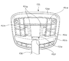
まず、図1及び図2を主に参照して、脚付き椅子Sの主な構成について説明する。ここで、図1は、本発明の実施形態に係る脚付き椅子Sの外観図、図2は、保持カバー71が取り付けられるクッションパンF21の下面を示す下側斜視図である。
脚付き椅子Sは、主に、脚部材F3と、脚部材F3に取り付けられて着座者の臀部を支持するクッションパンF21と、クッションパンF21に連結された背もたれ部であるバックパンF22と、覚醒機器Uとから構成されている。
First, the main configuration of the chair S with legs will be described mainly with reference to FIGS. 1 and 2. Here, FIG. 1 is an external view of a chair S with legs according to an embodiment of the present invention, and FIG. 2 is a lower perspective view showing a lower surface of a cushion pan F21 to which a
The chair S with legs mainly includes a leg member F3, a cushion pan F21 attached to the leg member F3 to support the buttocks of the occupant, a back pan F22 which is a backrest connected to the cushion pan F21, and awakening. And a device U.
脚部材F3は、4本に分岐する足部F31と、足部F31に連続的に形成された支柱筒F30とから構成されて、主に樹脂材料から形成されている。
足部F31における4本に分岐したそれぞれの先端には、キャスター31aが取り付けられている。
また、足部F31は、本実施形態においては4本に分岐する構成となっているが、3本以上に分岐する構成であってもよく、さらに、キャスター31aを備えなくてもよい。
The leg member F3 includes a foot portion F31 that branches into four, and a column tube F30 that is formed continuously with the foot portion F31, and is mainly formed of a resin material.
A caster 31a is attached to each of the four branched ends of the foot F31.
Further, in the present embodiment, the foot portion F31 has a configuration of branching into four, but may have a configuration of branching into three or more, and may not include the casters 31a.
支柱筒F30は、足部F31の中央に固定されて上方に延在している。支柱筒F30の中に、後述する支柱F21aが通されて固定される。 The support tube F30 is fixed to the center of the foot portion F31 and extends upward. A support column F21a, which will be described later, is passed through and fixed to the support cylinder F30.
クッションパンF21は、本発明に係る座部に相当するものであり、図2に示すように、椅子の幅方向に延在する下フレーム部F21bと、これに十字に成して交差して延在する上フレーム部F21cと、これらの上部に取り付けられた樹脂プレートF21dと、樹脂プレートF21dの上部に取り付けられた表皮付きパッド部F21eと、から構成されている。 The cushion pan F21 corresponds to a seat portion according to the present invention, and as shown in FIG. 2, a lower frame portion F21b extending in the width direction of the chair, and a lower frame portion F21b extending in a cross shape with the lower frame portion F21b. An upper frame portion F21c, a resin plate F21d attached to the upper portion thereof, and a pad portion F21e with a skin attached to the upper portion of the resin plate F21d.
下フレーム部F21bは、クッションパンF21の後ろ側において椅子の幅方向に延在しており、支柱F21aが通る下フレーム部F21bの中央には、貫通孔F21fが形成されている。 The lower frame portion F21b extends in the width direction of the chair behind the cushion pan F21, and a through hole F21f is formed in the center of the lower frame portion F21b through which the support post F21a passes.
上フレーム部F21cは、本発明に係る金属フレームに相当するものであり、椅子の幅方向中央において椅子の前後方向延在して、下フレーム部F21bと溶接によって接合されている。上フレーム部F21cの中央には、周囲に対して垂直に延在するパイプ状の支柱F21aが溶接等によって接合されている。
また、上フレーム部F21cにおける下フレーム部F21bよりも椅子の前後方向前側には、前後に延在する2個の凹部F21gが形成されており、椅子の幅方向に波打つように湾曲して形成されて剛性が高められている。
上フレーム部F21cにおける凹部F21gよりも椅子の幅方向の両外側には、本発明に係る締結部材に相当するタッピングネジN1(図3参照)を通す通し孔F21hが、前後に2つずつ形成されている。
具体的には、この通し孔F21hは、上フレーム部F21c及び一体的に接合された下フレーム部F21b、及び後述する保持カバー71を樹脂プレートF21dへ取り付けるタッピングネジN1を通すためのものである。
The upper frame portion F21c corresponds to the metal frame according to the present invention, extends in the front-rear direction of the chair at the center in the width direction of the chair, and is joined to the lower frame portion F21b by welding. At the center of the upper frame portion F21c, a pipe-like column F21a extending perpendicular to the periphery is joined by welding or the like.
Further, two recesses F21g extending in the front-rear direction are formed in the upper frame portion F21c on the front side in the front-rear direction of the chair relative to the lower frame portion F21b, and are formed so as to be wavy in the width direction of the chair. And rigidity is increased.
Two through holes F21h for passing a tapping screw N1 (see FIG. 3) corresponding to a fastening member according to the present invention are formed on both outer sides of the chair in the width direction of the chair than the concave portion F21g in the upper frame portion F21c. ing.
Specifically, the through-hole F21h is for passing a tapping screw N1 for attaching an upper frame portion F21c, a lower frame portion F21b integrally joined thereto, and a holding
表皮付きパッド部F21eは、ウレタン等のクッション材から成るパッドと、パッドを覆う表皮とから構成されており、表皮とパッドの間に後述する呼吸センサ9が配設されている。
The pad portion with skin F21e is composed of a pad made of a cushion material such as urethane and a skin covering the pad, and a
バックパンF22は、クッションパンF21の後部と連結されており、クッションパンF21から鉛直上方に延在して形成されている。
バックパンF22の内部の中央には、図1に示すように振動装置35が取り付けられている。この振動装置35は、詳細については後述するが、覚醒機器Uを構成部品であり、ECU7の制御信号に応じて着座者に振動刺激を付加するものである。
The back pan F22 is connected to the rear part of the cushion pan F21, and extends vertically upward from the cushion pan F21.
At the center inside the back pan F22, a
<覚醒機器について>
次いで、覚醒機器Uについて説明する。
本実施形態に係る覚醒機器Uは、ECU7、バッテリ8、呼吸センサ9及び振動装置35から主に構成されている。
<About Awakening Equipment>
Next, the awakening device U will be described.
The awakening device U according to the present embodiment mainly includes an ECU 7, a
振動装置35は、本発明に係る刺激装置に相当し、公知のアンバランスマスモータから成る所謂「振動モータ」を備える装置である。
The
ECU7は、本発明に係る制御装置に相当するものであり、電気制御を総合的に実行する中枢機能であり、本例においては、呼吸の間隔を示すデジタル信号に変換された電位差信号を基に、振動装置35を駆動制御する機能を有する。
本実施形態に係るECU7は、演算制御用のCPU、ROM、RAM等を備えて構成された、ハード的には汎用のECUである。
The ECU 7 is equivalent to a control device according to the present invention, and is a central function that comprehensively executes electric control. In this example, the ECU 7 is based on a potential difference signal converted into a digital signal indicating a breathing interval. And a function of driving and controlling the
The ECU 7 according to the present embodiment is a general-purpose ECU in terms of hardware, including a CPU, a ROM, a RAM, and the like for arithmetic control.
なお、ECU7に入力される信号は、信号処理回路によってデジタル信号に変換された電位差信号であり、出力されるものは、振動装置35を駆動するための電力である。
RAMは、演算制御中の信号及び入出力される信号を含むパラメータを一時記憶するもので、デジタル信号に変換された電位差信号その他の信号を格納する格納部として機能する。
The signal input to the ECU 7 is a potential difference signal converted into a digital signal by a signal processing circuit, and the output is power for driving the
The RAM temporarily stores parameters including signals under arithmetic control and input / output signals, and functions as a storage unit that stores a potential difference signal converted into a digital signal and other signals.
ROMは、CPUが実行するプログラム及び所定値のパラメータを記憶するものであり、例えば、所定の基準値を設定する基準値設定部や、基準値に基づき覚醒状態を判定する判定部、振動装置35を駆動する駆動部等がプログラムとして記録されている。
この駆動部は、CPUの指示に応じて電力を供給することにより振動装置35を駆動する機能を有する。
このCPUの指示信号は、呼吸センサ9からの信号を演算することにより形成される。
つまり、呼吸センサ9から送信される信号により、着座者の覚醒状態を判断し、覚醒状態ではないと判断した場合に、振動装置35を駆動するための信号がCPUから発信されるよう構成されている。なお、当該構成は公知の構成が使用されていればよく、呼吸センサ9の代わりに心拍センサを用いるようにしてもよい。
The ROM stores a program executed by the CPU and a parameter of a predetermined value. For example, the ROM stores a reference value setting unit that sets a predetermined reference value, a determination unit that determines an awake state based on the reference value, and a
The driving unit has a function of driving the
The instruction signal of the CPU is formed by calculating a signal from the
In other words, it is configured that the awake state of the seated person is determined by the signal transmitted from the
覚醒機器Uを構成するECU7は、保持カバー71によってクッションパンF21の下面側に取り付けられており(図5参照)、振動装置35は、図1に示すように、バックパンF22の着座者側を向く面の中央部付近に取り付けられている。
The ECU 7 constituting the awakening device U is attached to the lower surface side of the cushion pan F21 by the holding cover 71 (see FIG. 5), and the
バッテリ8は、ECU7及び振動装置35に電力を供給する機能を有し、本実施形態においては板状に形成されており、前面に給電端子が形成されている。バッテリ8は、給電端子から図示せぬ充電コードの接続することによって家庭用電源から充電されるものである。そして、バッテリ8は、スマートフォン等の充電用に使用されるバッテリを転用することが可能である。
なお、バッテリ8は、充電式のものに限定されず、使い切りタイプの着脱式のものであってもよい。
The
In addition, the
次いで、図3〜図5を参照して、ECU7及びバッテリ8の取付けについて説明する。
ここで、図3は、脚付き椅子Sに取り付けられるECU7、バッテリ8及び保持カバー71等の分解斜視図、図4は、脚付き椅子Sに取り付けられるECU7、バッテリ8及び保持カバー71の組付状態を示す斜視図、図5は、ECU7及びバッテリ8を保持する保持カバー71がクッションパンF21の下面に取り付けられた状態を示す模式的な正面図である。
Next, attachment of the ECU 7 and the
Here, FIG. 3 is an exploded perspective view of the ECU 7, the
本実施形態においては、ECU7は、ベース部材72及びカバー部材73によって覆われて支持され、さらにバッテリ8とともに、保持カバー71によって保持されて上フレーム部F21cに取り付けられる。
In the present embodiment, the ECU 7 is covered and supported by the
図3に示すように、保持カバー71は、本発明に係る保持部材及び樹脂部に相当するものであり、上方が開放されており鉛直断面が略コ字形状である収容凹溝71aと、その上部の両端から外側上方へとフランジ状に延出するパン取付部71bとを備え、樹脂材料で形成されている。パン取付部71bは、本発明に係る突出部に相当するものであり、パン取付部71bには、タッピングネジN1が通されるパン取付孔71cが形成されている。
As shown in FIG. 3, the holding
また、保持カバー71の椅子の幅方向両側の内壁には、下部が椅子の幅方向に長く形成されたL字状のリブ71dが椅子の前後方向に複数並んで形成されている。このリブ71d上に、後述するベース部材72が載置される。椅子の幅方向の一対のリブ71dの下部は、椅子の幅方向において、バッテリ8が間に収まるようにバッテリ8の長さよりも長い間隔で形成されており、バッテリ8の上下方向の厚さよりも高い高さで形成されている。
さらに、保持カバー71の椅子の前後方向における最前にあるリブ71eは、他のリブ71dよりも上部が椅子の幅方向に張り出して形成されている。より具体的には、椅子の幅方向両側にある一対のリブ71e間の長さは、後述するカバー部材73の椅子の幅方向の長さよりも短く設定されている。
このため、ECU7を覆って保持カバー71に保持されたカバー部材73は、リブ71eによって前方への移動を制限されることとなる。
A plurality of L-shaped
Further, the
For this reason, the
保持カバー71の底壁の前側には、椅子の幅方向両側を前端から後方に切り欠かれて形成された片持ち切片71fが形成されている。
片持ち切片71fの前端には、上方に突出して椅子の幅方向に連続する山状の係止突起71gが形成されている。
この片持ち切片71fは、後述するバッテリ8を保持カバー71から着脱可能に支持するためのものである。
詳細には、片持ち切片71fは、外力の加わらない通常状態においては、係止突起71gがバッテリ8に係止することによって保持する。
一方で、保持カバー71内に取り付けられたバッテリ8を前方に引っ張ると、係止突起71gに当接して撓むことでバッテリ8を取り外すことができる。
On the front side of the bottom wall of the holding
At the front end of the
The
Specifically, the
On the other hand, when the
ベース部材72及びカバー部材73は、鉛直断面が略コ字形状の枠体である。
詳細には、ベース部材72は、略コ字形状の断面を有して、幅方向長さよりも長く前後方向に延在している。
一方、カバー部材73は、略コ字形状の断面を有して、前後方向長さよりも長く幅方向に延在している。
特に、カバー部材73の前面には、ECU7の図示せぬカプラを露出させて、カプラによってECU7と呼吸センサ9又は振動装置35とを接続するため、方形状の切り欠きが形成されている。
これらは、上下に重ね合わせられることで、内部にECU7の格納空間を形成する。
そして、ベース部材72とカバー部材73とは、ECU7を格納した状態で固定ネジN2によって締結され、バッテリ8の上に積層されて、収容凹溝71a内に保持される。
The
Specifically, the
On the other hand, the
Particularly, a rectangular notch is formed on the front surface of the
These are superimposed on each other to form a storage space for the ECU 7 therein.
Then, the
なお、ベース部材72が前後に間隔を空けて配置されたリブ71d上に載置されることで、ECU7から生じる熱を帯びた空気は、ベース部材72の開放部を介してリブ71dの間を通ることとなる。このため、ECU7の放熱性を良好にすることができる。
さらに、リブ71dの下部がバッテリ8の上下方向の厚さよりも高い高さで形成されていることで、リブ71d上に配置される保持カバー71とバッテリ8とを離間させることができる。
このように、保持カバー71とバッテリ8とが離間して配置されることで、両者の間の熱が直接的に伝わることを防止し、両者相互の温度上昇を抑制することができる。
Since the
Furthermore, since the lower part of the
As described above, by disposing the holding
バッテリ8は、ECU7よりもクッションパンF21から離れた下方に設けられている。このようにバッテリ8が配置されていることで、着座者は、クッションパンF21に座った状態のままでバッテリ8まで手を伸ばすことが容易となる。つまり、着座者は、クッションパンF21に座った状態のままでバッテリ8を着脱、あるいは充電することが容易となり、作業性が良好となる。
そして、バッテリ8の上方に、メンテナンス以外では頻繁に触れることのないECU7を配置することで、脚付き椅子Sのデッドスペースを有効に利用することができる。
The
The dead space of the chair S with legs can be effectively used by arranging the ECU 7 above the
このように、ベース部材72とカバー部材73との複合体は、格納空間にECU7が格納された状態で、バッテリ8とともに保持カバー71の溝内部に格納され、この状態で、パン取付部71b(本例では2個存在する)に形成されたパン取付孔71c(本例では4個存在する)からタッピングネジN1により、クッションパンF21に留め付けられる。
詳細には、タッピングネジN1は、パン取付孔71c、及び上フレーム部F21cの通し孔F21hを通って、樹脂プレートF21dにタッピング留めされる。
つまり、保持カバー71は、凹部F21gを有して支柱F21aと一体に形成されていることで剛性の高い上フレーム部F21cに当接した状態でタッピングネジN1によって固定されることとなるため、取付強度を高くすることができる。
As described above, the complex of the
More specifically, the tapping screw N1 passes through the
That is, since the holding
さらに、タッピングネジN1は、樹脂製のパン取付部71bにネジ頭の下面が当接した状態でタッピング留めされる。このため、タッピングネジN1による締結強度は金属面に当接する場合よりも高まることとなる。
そして、パン取付部71bの厚み分、保持カバー71を取り付けずに直接上フレーム部F21cを樹脂プレートF21dに取り付ける場合よりも、ネジ頭の下面に作用する反力が高まることで、タッピングネジN1の緩みを生じづらくすることが可能となる。
なお、カバー部材73は、樹脂材料から形成されると好ましいが、上記効果を得ることのみに着目すれば、タッピングネジN1によって締結される部分のみが樹脂材料で形成されていてもよい。
Further, the tapping screw N1 is tapped and fixed in a state where the lower surface of the screw head is in contact with the resin
Then, the reaction force acting on the lower surface of the screw head is increased by the thickness of the
The
図5に示すように、保持カバー71が上フレーム部F21cに取り付けられた状態においては、上フレーム部F21cに当接するパン取付部71bがカバー部材73よりも上方に突出しているために、カバー部材73と上フレーム部F21cとの間に空間SPが形成される。
このように、形成された空間SPによって、ECU7及びバッテリ8からの発熱を放熱することができる。
さらに、空間SPの一部を利用して、呼吸センサ9、振動装置35、ECU7及びバッテリ8の少なくともいずれかに繋がる図示せぬハーネスを配設することも可能である。
As shown in FIG. 5, in a state where the holding
Thus, the heat generated from the ECU 7 and the
Furthermore, a harness (not shown) connected to at least one of the
なお、保持カバー71に保持されたバッテリ8の充電端子に、例えばオス−メス端子を備える図示せぬ延長ケーブルを接続して、キャスターF31aの上方にある足部F31の先端に充電口を配設するようにしてもよい。
このようにすれば、着座者は、クッションパンF21の下面近傍よりも足部F31の先端の方が容易に目視できるため、バッテリ8の充電コードの接続をより容易に行なうことができる。
この場合には、特に、支柱筒F30及び足部F31の内部に、不図示の延長ケーブルを配設するようにすると好ましい。
なお、図示は省略するが、通電表示用のLED等が搭載されていてもよい。
An extension cable (not shown) having, for example, a male-female terminal is connected to the charging terminal of the
By doing so, the seated person can more easily see the tip of the foot portion F31 than near the lower surface of the cushion pan F21, so that the charging cord of the
In this case, it is particularly preferable to arrange an extension cable (not shown) inside the support cylinder F30 and the foot F31.
Although illustration is omitted, an LED or the like for displaying electricity may be mounted.
F21 クッションパン(座部)
F21a 支柱
F21b 下フレーム部
F21c 上フレーム部(金属フレーム)
F21d 樹脂プレート
F21e 表皮付きパッド部
F21f 貫通孔
F21g 凹部
F21h 通し孔
F22 バックパン
F3 脚部材
F30 支柱筒
F31 足部
F31a キャスター
N1 タッピングネジ(締結部材)
N2 固定ネジ
S 脚付き椅子
SP 空間
U 覚醒機器
31a キャスター
35 振動装置(刺激装置)
7 ECU(制御装置)
71 保持カバー(保持部材、樹脂部)
71a 収容凹溝
71b パン取付部(突出部)
71c パン取付孔
71d,71e リブ
71f 片持ち切片
71g 係止突起
72 ベース部材
73 カバー部材
8 バッテリ
9 呼吸センサ
F21 Cushion pan (seat)
F21a Support F21b Lower frame F21c Upper frame (metal frame)
F21d Resin plate F21e Pad portion with skin F21f Through hole F21g Depression F21h Through hole F22 Back pan F3 Leg member F30 Support tube F31 Foot F31a Caster N1 Tapping screw (fastening member)
N2 Fixing screw S Chair with legs SP Space U Awakening
7 ECU (control device)
71 Holding cover (holding member, resin part)
71c
Claims (1)
該脚部材に接続された支柱と、
該支柱と一体化されており、座部を構成する金属フレームと、
着座者に刺激を加える刺激装置と該刺激装置を制御する制御装置とを有して前記着座者を覚醒させる覚醒機器と、
該覚醒機器に電力を供給するバッテリと、
前記バッテリ及び前記制御装置を保持する保持部材と、を備え、
該保持部材は、前記金属フレームに取り付けられていることを特徴とする椅子。 Leg members,
A column connected to the leg member;
A metal frame that is integrated with the column and constitutes a seat;
A wake-up device that wakes up the occupant having a stimulating device that applies a stimulus to the occupant and a control device that controls the stimulating device;
A battery for supplying power to the awakening device;
A holding member that holds the battery and the control device,
The chair, wherein the holding member is attached to the metal frame.
Priority Applications (1)
| Application Number | Priority Date | Filing Date | Title |
|---|---|---|---|
| JP2019145576A JP2020006183A (en) | 2019-08-07 | 2019-08-07 | Chair |
Applications Claiming Priority (1)
| Application Number | Priority Date | Filing Date | Title |
|---|---|---|---|
| JP2019145576A JP2020006183A (en) | 2019-08-07 | 2019-08-07 | Chair |
Related Parent Applications (1)
| Application Number | Title | Priority Date | Filing Date |
|---|---|---|---|
| JP2015067212A Division JP6569265B2 (en) | 2015-03-27 | 2015-03-27 | Chair |
Publications (1)
| Publication Number | Publication Date |
|---|---|
| JP2020006183A true JP2020006183A (en) | 2020-01-16 |
Family
ID=69149998
Family Applications (1)
| Application Number | Title | Priority Date | Filing Date |
|---|---|---|---|
| JP2019145576A Pending JP2020006183A (en) | 2019-08-07 | 2019-08-07 | Chair |
Country Status (1)
| Country | Link |
|---|---|
| JP (1) | JP2020006183A (en) |
Citations (6)
| Publication number | Priority date | Publication date | Assignee | Title |
|---|---|---|---|---|
| JPS6342259U (en) * | 1986-09-09 | 1988-03-19 | ||
| JPH03127373U (en) * | 1990-04-03 | 1991-12-20 | ||
| JPH06253953A (en) * | 1993-03-05 | 1994-09-13 | Fukuoka Kagaku Kk | Vibration chair to prevent sleep |
| JPH09164863A (en) * | 1996-10-21 | 1997-06-24 | Fukuoka Kagaku Kk | Seat vibration device for prevention of sleepless driving |
| JP2003038283A (en) * | 2001-08-01 | 2003-02-12 | Kokuyo Co Ltd | Tilt chair, tilt unit, and method of manufacturing tilt chair |
| JP2006503599A (en) * | 2002-02-27 | 2006-02-02 | ホ チョ,ミョン | Posture sensing tool |
-
2019
- 2019-08-07 JP JP2019145576A patent/JP2020006183A/en active Pending
Patent Citations (6)
| Publication number | Priority date | Publication date | Assignee | Title |
|---|---|---|---|---|
| JPS6342259U (en) * | 1986-09-09 | 1988-03-19 | ||
| JPH03127373U (en) * | 1990-04-03 | 1991-12-20 | ||
| JPH06253953A (en) * | 1993-03-05 | 1994-09-13 | Fukuoka Kagaku Kk | Vibration chair to prevent sleep |
| JPH09164863A (en) * | 1996-10-21 | 1997-06-24 | Fukuoka Kagaku Kk | Seat vibration device for prevention of sleepless driving |
| JP2003038283A (en) * | 2001-08-01 | 2003-02-12 | Kokuyo Co Ltd | Tilt chair, tilt unit, and method of manufacturing tilt chair |
| JP2006503599A (en) * | 2002-02-27 | 2006-02-02 | ホ チョ,ミョン | Posture sensing tool |
Similar Documents
| Publication | Publication Date | Title |
|---|---|---|
| JP6963191B2 (en) | Chair | |
| JP6565281B2 (en) | Chair | |
| US12240366B2 (en) | Chair | |
| JP7518434B2 (en) | Sheet | |
| JP2022125257A (en) | Chair | |
| JP2021035600A (en) | Chair | |
| JP6569265B2 (en) | Chair | |
| JP7401782B2 (en) | seat with sensor | |
| JP6600965B2 (en) | Chair | |
| JP6795772B2 (en) | Chair | |
| WO2018092430A1 (en) | Seat device | |
| JP6565282B2 (en) | Chair | |
| JP6257073B2 (en) | Chair | |
| JP6212067B2 (en) | Chair | |
| JP6620414B2 (en) | Chair | |
| JP7089206B2 (en) | Chair | |
| JP6600966B2 (en) | Chair | |
| JP2026078466A (en) | chair | |
| WO2017183419A1 (en) | Chair |
Legal Events
| Date | Code | Title | Description |
|---|---|---|---|
| A621 | Written request for application examination |
Free format text: JAPANESE INTERMEDIATE CODE: A621 Effective date: 20190905 |
|
| A131 | Notification of reasons for refusal |
Free format text: JAPANESE INTERMEDIATE CODE: A131 Effective date: 20200519 |
|
| A601 | Written request for extension of time |
Free format text: JAPANESE INTERMEDIATE CODE: A601 Effective date: 20200717 |
|
| A02 | Decision of refusal |
Free format text: JAPANESE INTERMEDIATE CODE: A02 Effective date: 20201208 |