JP2020006440A - Gate for tablet discharge part of tablet press and actuation method for gate - Google Patents
Gate for tablet discharge part of tablet press and actuation method for gate Download PDFInfo
- Publication number
- JP2020006440A JP2020006440A JP2019116856A JP2019116856A JP2020006440A JP 2020006440 A JP2020006440 A JP 2020006440A JP 2019116856 A JP2019116856 A JP 2019116856A JP 2019116856 A JP2019116856 A JP 2019116856A JP 2020006440 A JP2020006440 A JP 2020006440A
- Authority
- JP
- Japan
- Prior art keywords
- gate
- tablet
- switching position
- discharge
- press
- Prior art date
- Legal status (The legal status is an assumption and is not a legal conclusion. Google has not performed a legal analysis and makes no representation as to the accuracy of the status listed.)
- Granted
Links
Images



Classifications
-
- B—PERFORMING OPERATIONS; TRANSPORTING
- B65—CONVEYING; PACKING; STORING; HANDLING THIN OR FILAMENTARY MATERIAL
- B65G—TRANSPORT OR STORAGE DEVICES, e.g. CONVEYORS FOR LOADING OR TIPPING, SHOP CONVEYOR SYSTEMS OR PNEUMATIC TUBE CONVEYORS
- B65G47/00—Article or material-handling devices associated with conveyors; Methods employing such devices
- B65G47/74—Feeding, transfer, or discharging devices of particular kinds or types
- B65G47/76—Fixed or adjustable ploughs or transverse scrapers
- B65G47/766—Adjustable ploughs or transverse scrapers
-
- A—HUMAN NECESSITIES
- A61—MEDICAL OR VETERINARY SCIENCE; HYGIENE
- A61K—PREPARATIONS FOR MEDICAL, DENTAL OR TOILETRY PURPOSES
- A61K9/00—Medicinal preparations characterised by special physical form
- A61K9/20—Pills, tablets, discs, rods
-
- B—PERFORMING OPERATIONS; TRANSPORTING
- B30—PRESSES
- B30B—PRESSES IN GENERAL
- B30B11/00—Presses specially adapted for forming shaped articles from material in particulate or plastic state, e.g. briquetting presses, tabletting presses
- B30B11/02—Presses specially adapted for forming shaped articles from material in particulate or plastic state, e.g. briquetting presses, tabletting presses using a ram exerting pressure on the material in a moulding space
- B30B11/14—Presses specially adapted for forming shaped articles from material in particulate or plastic state, e.g. briquetting presses, tabletting presses using a ram exerting pressure on the material in a moulding space co-operating with moulds on a movable carrier other than a turntable or a rotating drum
-
- B—PERFORMING OPERATIONS; TRANSPORTING
- B07—SEPARATING SOLIDS FROM SOLIDS; SORTING
- B07C—POSTAL SORTING; SORTING INDIVIDUAL ARTICLES, OR BULK MATERIAL FIT TO BE SORTED PIECE-MEAL, e.g. BY PICKING
- B07C5/00—Sorting according to a characteristic or feature of the articles or material being sorted, e.g. by control effected by devices which detect or measure such characteristic or feature; Sorting by manually actuated devices, e.g. switches
- B07C5/36—Sorting apparatus characterised by the means used for distribution
- B07C5/361—Processing or control devices therefor, e.g. escort memory
- B07C5/362—Separating or distributor mechanisms
-
- B—PERFORMING OPERATIONS; TRANSPORTING
- B30—PRESSES
- B30B—PRESSES IN GENERAL
- B30B11/00—Presses specially adapted for forming shaped articles from material in particulate or plastic state, e.g. briquetting presses, tabletting presses
- B30B11/005—Control arrangements
-
- B—PERFORMING OPERATIONS; TRANSPORTING
- B30—PRESSES
- B30B—PRESSES IN GENERAL
- B30B11/00—Presses specially adapted for forming shaped articles from material in particulate or plastic state, e.g. briquetting presses, tabletting presses
- B30B11/02—Presses specially adapted for forming shaped articles from material in particulate or plastic state, e.g. briquetting presses, tabletting presses using a ram exerting pressure on the material in a moulding space
-
- B—PERFORMING OPERATIONS; TRANSPORTING
- B30—PRESSES
- B30B—PRESSES IN GENERAL
- B30B11/00—Presses specially adapted for forming shaped articles from material in particulate or plastic state, e.g. briquetting presses, tabletting presses
- B30B11/02—Presses specially adapted for forming shaped articles from material in particulate or plastic state, e.g. briquetting presses, tabletting presses using a ram exerting pressure on the material in a moulding space
- B30B11/08—Presses specially adapted for forming shaped articles from material in particulate or plastic state, e.g. briquetting presses, tabletting presses using a ram exerting pressure on the material in a moulding space co-operating with moulds carried by a turntable
-
- B—PERFORMING OPERATIONS; TRANSPORTING
- B30—PRESSES
- B30B—PRESSES IN GENERAL
- B30B15/00—Details of, or accessories for, presses; Auxiliary measures in connection with pressing
- B30B15/26—Program-control arrangements
-
- B—PERFORMING OPERATIONS; TRANSPORTING
- B30—PRESSES
- B30B—PRESSES IN GENERAL
- B30B15/00—Details of, or accessories for, presses; Auxiliary measures in connection with pressing
- B30B15/30—Feeding material to presses
-
- B—PERFORMING OPERATIONS; TRANSPORTING
- B30—PRESSES
- B30B—PRESSES IN GENERAL
- B30B15/00—Details of, or accessories for, presses; Auxiliary measures in connection with pressing
- B30B15/30—Feeding material to presses
- B30B15/302—Feeding material in particulate or plastic state to moulding presses
- B30B15/304—Feeding material in particulate or plastic state to moulding presses by using feed frames or shoes with relative movement with regard to the mould or moulds
-
- B—PERFORMING OPERATIONS; TRANSPORTING
- B30—PRESSES
- B30B—PRESSES IN GENERAL
- B30B15/00—Details of, or accessories for, presses; Auxiliary measures in connection with pressing
- B30B15/32—Discharging presses
-
- B—PERFORMING OPERATIONS; TRANSPORTING
- B65—CONVEYING; PACKING; STORING; HANDLING THIN OR FILAMENTARY MATERIAL
- B65G—TRANSPORT OR STORAGE DEVICES, e.g. CONVEYORS FOR LOADING OR TIPPING, SHOP CONVEYOR SYSTEMS OR PNEUMATIC TUBE CONVEYORS
- B65G43/00—Control devices, e.g. for safety, warning or fault-correcting
- B65G43/08—Control devices operated by article or material being fed, conveyed or discharged
Landscapes
- Mechanical Engineering (AREA)
- Engineering & Computer Science (AREA)
- Health & Medical Sciences (AREA)
- Animal Behavior & Ethology (AREA)
- Epidemiology (AREA)
- Life Sciences & Earth Sciences (AREA)
- Pharmacology & Pharmacy (AREA)
- General Health & Medical Sciences (AREA)
- Public Health (AREA)
- Veterinary Medicine (AREA)
- Medicinal Chemistry (AREA)
- Chemical & Material Sciences (AREA)
- Medical Preparation Storing Or Oral Administration Devices (AREA)
Abstract
【課題】手間および危険性が最小化される回転式タブレットプレス排出部のゲートおよび作動方法を提供する。【解決手段】回転式タブレットプレスの排出のゲート50であって、制御装置からの切替信号によってタブレットが第1のタブレット排出口に供給される第1の切換位置と、タブレットが第2のタブレット排出口に供給される第2の切換位置との間でゲート50を移動させる駆動装置が設けられ、ゲート50が第1の切換位置および(または)第2の切換位置へ到達したことを検出するセンサが設けられているゲート50において、センサからの検出信号が制御装置に印加されて、ゲート50をホーム切換位置から目標切換位置に移動させる信号がある場合、および目標切換位置に到達した信号がない場合、ゲートをホーム切換位置に戻す信号を出力し、その後ゲート50を再び目標切換位置に向かって移動させる切替信号を出力するゲート50とその作動方法。【選択図】図2Kind Code: A1 A rotary tablet press discharge gate and method of operation with minimal effort and risk. Kind Code: A1 A discharge gate of a rotary tablet press, comprising: a first switching position at which a tablet is supplied to a first tablet discharge port by a switching signal from a control device; A drive is provided for moving the gate 50 between a second switching position supplied to the outlet and a sensor for detecting that the gate 50 has reached the first switching position and / or the second switching position. A detection signal from the sensor is applied to the control device to provide a signal for moving the gate 50 from the home switching position to the target switching position, and there is no signal that has reached the target switching position. In this case, a gate that outputs a signal for returning the gate to the home switching position, and then outputs a switching signal that moves the gate 50 toward the target switching position again 0 and its method of operation. [Selection diagram] FIG.
Description
本発明は、タブレットプレス(特に、回転式タブレットプレス)のタブレット排出部のためのゲートであって、制御装置が設けられており、制御装置からの切替信号によってタブレットが第1のタブレット排出口に供給される第1の切換位置と、タブレットが少なくとも1つの第2のタブレット排出口に供給される少なくとも1つの第2の切換位置との間でゲートを移動させる駆動装置が設けられており、ゲートが第1の切換位置および少なくとも1つの第2の切換位置へ到達したことを検出するために少なくとも1つのセンサが設けられているゲートに関する。 The present invention relates to a gate for a tablet discharge unit of a tablet press (particularly, a rotary tablet press), wherein a control device is provided, and a tablet is connected to a first tablet discharge port by a switching signal from the control device. A drive is provided for moving the gate between a first switching position to be supplied and at least a second switching position at which the tablet is supplied to at least one second tablet outlet; Is associated with a gate provided with at least one sensor for detecting that it has reached a first switching position and at least one second switching position.
本発明はさらに、タブレットプレス(特に、回転式タブレットプレス)のタブレット排出部のためのゲートを作動させるための方法であって、ゲートが、タブレットが第1のタブレット排出口に供給される第1の切換位置と、タブレットが少なくとも1つの第2のタブレット排出口に供給される少なくとも1つの第2の切換位置との間で移動され、少なくとも1つのセンサによって、ゲートが第1の切換位置および少なくとも1つの第2の切換位置に到達したことを検出する方法に関する。 The present invention is further directed to a method for operating a gate for a tablet discharge of a tablet press (particularly a rotary tablet press), wherein the gate comprises a first tablet discharge port where the tablet is supplied to a first tablet discharge port. And the tablet is moved between at least one second switching position where the tablet is supplied to at least one second tablet outlet, and the gate is moved by the at least one sensor to the first switching position and at least one. It relates to a method for detecting that one second switching position has been reached.
回転式タブレットプレスは、回転式タブレットプレスのロータのダイプレートのキャビティに常に対で割り当てられている複数の上部パンチおよび下部パンチを有する。ロータが回転している間、キャビティはプレスされるべき充填材料で充填される。少なくとも1つのプレス装置では、上部パンチおよび下部パンチがキャビティ内で互いに押し付けられて充填材料をタブレットにプレスする。プレス後、タブレットは一般的に下部パンチによってキャビティから排出され、例えばスクレーパによってタブレット排出部に供給される。取り出されたタブレットは、例えば、回転式タブレットプレスのセンサからの測定値を用いて、異なるタブレット排出口(例えば、良好なタブレット用のタブレット排出口、不良のタブレット用のタブレット排出口、またはサンプリング用のタブレット用のタブレット排出口)に供給される。タブレットを異なるタブレット排出口に誘導するために、回転式タブレットプレスのタブレット排出口にはゲートが通常見られる。そのようなゲートは、例えば、切換位置に応じてタブレットを第1のタブレット排出口または第2のタブレット排出口に向ける2つの切換位置の間で枢動自在に動くことができるゲートフラップを有することができる。 The rotary tablet press has a plurality of upper and lower punches that are always assigned in pairs to the cavities of the die plate of the rotor of the rotary tablet press. While the rotor is rotating, the cavity is filled with the filling material to be pressed. In at least one pressing device, an upper punch and a lower punch are pressed together in a cavity to press the filling material into tablets. After pressing, the tablet is generally ejected from the cavity by a lower punch and is supplied to the tablet ejector by, for example, a scraper. The dispensed tablet can be used, for example, using a reading from a rotary tablet press sensor to provide a different tablet outlet (eg, a tablet outlet for a good tablet, a tablet outlet for a bad tablet, or a sampling outlet). Tablet outlet for tablets). Gates are usually found at the tablet outlet of the rotary tablet press to guide the tablet to different tablet outlets. Such a gate has, for example, a gate flap which can be pivotally moved between two switching positions for directing the tablet to a first tablet outlet or a second tablet outlet depending on the switching position. Can be.
ゲートのそれぞれの端部位置がセンサによっていつ到達したかを検出することが知られている。一般的に、2つの切換位置を有するゲートのそれぞれの端部位置を検出するために2つのセンサが設けられている。センサが端部位置に到達していないことを認識すると、対応するエラーメッセージが出力される。 It is known to detect when each end position of the gate has reached by a sensor. In general, two sensors are provided for detecting the respective end positions of a gate having two switching positions. When the sensor recognizes that the end position has not been reached, a corresponding error message is output.
現代の回転式タブレットプレスの高い生産能力に対応して、タブレットのかなりの流れがタブレット排出部を通って流れる。そうすることで、タブレットは互いにわずかな距離だけを有して流れる。ゲートを切り換えるとき、これは、ゲート(例えば、ゲートフラップの自由端)とタブレット排出部の反対側の壁との間でタブレットをクランプすることにつながる可能性がある。それに対応して、ゲートはその目標切換位置に到達することができない。これは、タブレット排出部におけるタブレットの詰まり、そしてゲートの誤動作による回転式タブレットプレスの遮断につながり得る。これは回転式タブレットプレスの利用可能性を著しく制限し、そして誤動作を排除するためのオペレータにとっての手動の手間が多い。したがって、タブレットの詰まりを解消するためには、回転式タブレットプレスのハウジングを開くことが必要であり、これは、特にプレス材料が有毒である場合には、健康上の危険性を高める。さらに、タブレット詰まりの領域にアクセス可能にするために、ゲート駆動装置、空気コラム、カバーなどのコンポーネントを取り除くことが通常必要である。詰まったタブレットならびにいかなる破片も取り除かなければならず、タブレット排出部はきれいにされなければならない。さらに、不良のタブレットまたは破片が意図せずに良好な製品に入っているかどうかをチェックしなければならない。その後、取り外したコンポーネントを再度取り付け、回転式タブレットプレスを再起動する必要がある。 Corresponding to the high production capacity of modern rotary tablet presses, a considerable flow of tablets flows through the tablet discharge. In doing so, the tablets flow with only a small distance from each other. When switching gates, this can lead to clamping the tablet between the gate (eg, the free end of the gate flap) and the opposite wall of the tablet discharge. Correspondingly, the gate cannot reach its target switching position. This can lead to tablet jams in the tablet discharge and shut off of the rotary tablet press due to malfunction of the gate. This severely limits the availability of rotary tablet presses and there is a lot of manual effort for the operator to eliminate malfunctions. It is therefore necessary to open the housing of the rotary tablet press in order to clear the tablet from jamming, which increases the health risks, especially if the press material is toxic. In addition, it is usually necessary to remove components such as gate drives, air columns, covers, etc. to make the area of tablet jam accessible. The clogged tablet as well as any debris must be removed and the tablet discharge must be cleaned. In addition, it must be checked whether a bad tablet or debris is unintentionally in a good product. After that, it is necessary to reinstall the removed components and restart the rotary tablet press.
説明された技術水準から出発して、本発明の目的は、高い生産能力でも回転式タブレットプレスの利用可能性が最大化され、オペレータにとっての手間および健康上の危険性が最小化される上述のタイプのゲートおよび方法を提供することである。 Starting from the state of the art described, the object of the present invention is to maximize the availability of rotary tablet presses even at high production capacities and to minimize the hassle and health risks for operators. It is to provide a type of gate and method.
本発明は、独立請求項1および9を介して目的を達成する。有利な実施形態は、従属請求項、明細書、および図面に開示されている。 The invention achieves the object through independent claims 1 and 9. Advantageous embodiments are disclosed in the dependent claims, the description and the drawings.
上述のタイプのゲートに対して、本発明は、少なくとも1つのセンサからの検出信号が制御装置に印加されており、制御装置は、ゲートをホーム切換位置から目標切換位置に向かって移動させるための切替信号がある場合、および目標切換位置に到達したという検出信号がない場合、部分的にまたは完全にゲートをホーム切換位置に戻すための切替信号を出力し、その後ゲートを再び目標切換位置に向かって移動させるための切替信号を出力するように設計されているという点で目的を達成する。 For a gate of the type described above, the present invention provides a control device wherein a detection signal from at least one sensor is applied to a control device, the control device comprising: a control device for moving the gate from a home switching position to a target switching position; If there is a switching signal, and if there is no detection signal indicating that the target switching position has been reached, a switching signal for partially or completely returning the gate to the home switching position is output, and then the gate is again moved to the target switching position. The object is achieved in that it is designed to output a switching signal for moving the camera.
上述のタイプの方法に対して、本発明は、ゲートをホーム切換位置から目標切換位置に向かって移動させる間に目標切換位置へ到達したことが検出されないとき、ゲートを部分的にまたは完全にホーム切換位置に戻し、その後目標切換位置に向かって再び移動させるという点で目的を達成する。 For a method of the type described above, the present invention provides a method for partially or completely moving a gate home when it is not detected that the target switching position has been reached while moving the gate from the home switching position to the target switching position. The object is achieved in that it is returned to the switching position and then moved again towards the target switching position.
ゲートは、例えばホーム切換位置を形成することができる第1の切換位置と、例えば目標切換位置を形成することができる少なくとも1つの第2の切換位置との間で移動することができる。第1の切換位置および少なくとも1つの第2の切換位置、またはそれぞれホーム切換位置および目標切換位置は、ゲートの各端部位置、またはそれぞれゲートのゲートフラップである。これらの端部位置では、ゲートの排出チャネル間の分離、したがって所望のタブレット排出口へのタブレットの流れの誘導が保証される。少なくとも1つの端部位置において、ゲート、またはそれぞれゲートフラップは、例えばタブレット排出部の排出チャネルの内壁に当接することができる。しかしながら、少なくとも1つの端部位置では、それはタブレット排出部の異なる排出チャネル間の隔壁の一部を形成することもできる。 The gate can be moved between a first switching position, which can form a home switching position, for example, and at least one second switching position, which can form a target switching position, for example. The first switching position and the at least one second switching position, or respectively the home switching position and the target switching position, are the respective end positions of the gate or the gate flaps of the gate respectively. In these end positions, the separation between the discharge channels of the gate and thus the directing of the tablet flow to the desired tablet outlet is ensured. In at least one end position, the gate, or respectively the gate flap, can abut, for example, the inner wall of the discharge channel of the tablet discharge. However, in at least one end position, it can also form part of a partition between different discharge channels of the tablet discharge.
ゲートを第1の切換位置と少なくとも1つの第2の切換位置との間で移動させるための切換信号を発信する、本発明に係るゲート用の制御装置が提供される。制御装置は、例えばタブレットプレスのセンサからの測定値に起因して、またはサンプリングを行うための入力に起因して、切換信号を発信することができる。例えば、回転式タブレットプレスのセンサは、製造されたタブレットによるパラメータの許容できない偏差を認識することができる。これらの測定値は制御装置に印加することができ、これにしたがって制御装置は、対応するタブレットが不良タブレット用のタブレット排出口に供給される切換位置にゲートを移動させるための切換信号を出力することができる。サンプリングを行うための信号がある場合、制御装置はまた、サンプリング(すなわち、スポットチェック)のためのタブレット排出口に所与のタブレット量が供給される切換位置にゲートを移動させるための切換信号を出力することができる。制御装置は、同時に回転式タブレットプレスの動作を制御する(機械制御の)ための制御装置とすることができる。しかしながら、それはそのような機械制御とは別の制御装置でもあり得る。 A control device for a gate according to the invention is provided, which emits a switching signal for moving a gate between a first switching position and at least one second switching position. The control device can emit a switching signal, for example, due to a measurement from a sensor of the tablet press or due to an input for performing sampling. For example, the sensors of a rotary tablet press can recognize unacceptable deviations of the parameters due to the manufactured tablet. These measurements can be applied to the control device, which outputs a switching signal for moving the gate to the switching position where the corresponding tablet is supplied to the tablet outlet for the defective tablet. be able to. If there is a signal to perform the sampling, the controller also outputs a switching signal to move the gate to a switching position where a given tablet volume is supplied to the tablet outlet for sampling (ie, spot check). Can be output. The control device can be a control device for simultaneously controlling (mechanical control) the operation of the rotary tablet press. However, it can also be a separate control from such a machine control.
さらに、制御装置から受信した切換信号に応じてゲートを所望の切換位置に移動させる駆動装置が提供される。駆動装置は、例えば、ゲートを第1の切換位置と少なくとも1つの第2の切換位置との間で移動させる、例えばゲートフラップを枢動させる電気モータを含むことができる。しかしながら、例えば電磁駆動装置も考えられる。それ自体既知の方法で、(特に、ゲートの全ての端部位置)、すなわち、第1の切替位置および(または)少なくとも1つの第2の切替位置、あるいはそれぞれホーム切換位置および目標切換位置を1つまたは複数検出する少なくとも1つのセンサを設けている。いくつかのセンサはこのために設けられることができる。そうすることで、端部位置を直接または間接的に検出することができる。例えば、1つのセンサまたは複数のセンサは、それぞれの端部位置に到達したときまたは到達しなかったときに、他の測定値から推測することができる。例えば、誘導性センサまたはマイクロスイッチは、所与の各端部位置にいつ到達したか、または到達しなかったかを認識するセンサとして可能である。もちろん、それらは異なるセンサにすることもできる。角度センサは、ゲートフラップなどのゲートの角度位置を検出する例としても挙げられ、したがってゲートのすべての端部位置、および好ましくは任意のゲートの中間位置も検出することができる。 Further, there is provided a driving device for moving a gate to a desired switching position in response to a switching signal received from a control device. The drive can include, for example, an electric motor that moves the gate between a first switching position and at least one second switching position, for example, pivots a gate flap. However, for example, electromagnetic drives are also conceivable. In a manner known per se (particularly at all end positions of the gate), ie the first switching position and / or at least one second switching position, or the home switching position and the target switching position, respectively, by one At least one sensor that detects one or more is provided. Several sensors can be provided for this. By doing so, the end position can be detected directly or indirectly. For example, one or more sensors can be inferred from other measurements when they reach or do not reach their respective end positions. For example, an inductive sensor or microswitch is possible as a sensor that recognizes when or has not reached each given end position. Of course, they can be different sensors. An angle sensor is also mentioned as an example of detecting the angular position of a gate, such as a gate flap, so that it can also detect all end positions of the gate, and preferably any intermediate position of any gate.
ゲートが第1の切換位置などのホーム切換位置から少なくとも1つの第2の切換位置などの目標切換位置に移動する間、少なくとも1つのセンサは、目標切換位置に到達したかどうかを検出することができる。少なくとも1つのセンサからの測定信号を制御装置に印加することができる。ゲートをホーム切換位置から目標切換位置へ移動させるための切替信号が制御装置からあるのにもかかわらず、もし少なくとも1つのセンサから目標切換位置に到達したことが検出されない場合、制御装置は、部分的にまたは完全にゲートをホーム切替位置に戻すように駆動装置に切替信号を発信する。それに対応して、ゲートの移動方向を転換させるのと同時に、駆動装置は部分的にまたは完全にゲートをホーム切替位置に戻す。その後、制御装置は、再度移動方向を転換させるのと同時に、駆動装置に(再度)ゲートを目標切替位置に戻すための切替信号を発信する。駆動装置は、それに対応してゲートを目標切替位置に戻す。例えば、切替信号が出力された後、クリティカルタイム期間を指定することができ、それは目標切替位置に到達するために存在すべき少なくとも1つのセンサからの検出信号内に指定することができる。もし目標切替位置に到達するために存在する検出信号がなく、このクリティカルタイム期間を超えてしまった場合、ゲートは、部分的に戻される。このクリティカルタイム期間は例えば、ゲートをホーム切替位置から目標切替位置へ切替させるのに必要な期間よりわずかに大きいように選ばれている。 While the gate moves from a home switching position, such as a first switching position, to a target switching position, such as at least one second switching position, at least one sensor may detect whether the target switching position has been reached. it can. A measurement signal from at least one sensor can be applied to the controller. If at least one sensor does not detect that the target switching position has been reached, even though there is a switching signal from the control device for moving the gate from the home switching position to the target switching position, the control device performs A switching signal is sent to the drive to return the gate to the home switching position, either completely or completely. Correspondingly, at the same time as changing the direction of movement of the gate, the drive partially or completely returns the gate to the home switching position. Thereafter, the control device transmits a switching signal for returning the gate to the target switching position (again) to the driving device at the same time as changing the moving direction again. The drive correspondingly returns the gate to the target switching position. For example, after the switching signal is output, a critical time period can be specified, which can be specified in a detection signal from at least one sensor that must be present to reach the target switching position. If no detection signal is present to reach the target switching position and this critical time period has been exceeded, the gate is partially returned. The critical time period is selected, for example, to be slightly longer than a period required for switching the gate from the home switching position to the target switching position.
本発明は、目標切替位置に到達するための検出信号がないときに、ゲートとタブレット排出部の壁との間でタブレットがクランプされるという考えに基づく。排出のためこのクランプされたタブレットを開放するために、ゲートはそのホーム切替位置に戻される。したがって、ゲート、例えばゲートフラップとタブレット排出部の反対側の壁との間でクランプされたタブレットは、開放され、流れ出る。次いで、ゲートは、安全に目標切替位置を推定することができる。 The invention is based on the idea that the tablet is clamped between the gate and the wall of the tablet discharge when there is no detection signal to reach the target switching position. The gate is returned to its home switching position to release the clamped tablet for ejection. Thus, the gate, for example a tablet clamped between the gate flap and the wall opposite the tablet discharge, is released and flows out. The gate can then safely estimate the target switching position.
したがって、本発明は、タブレットのクランピングが依然として起こる可能性があることを推定している。しかしながら、直ちにおよび自動的に制御装置にそのようなクランピングの存在を解消させるように測定値を追跡する。特に、ゲートの指定された端部位置に到達しないとき、この情報によってゲートの移動方向が転換される。移動方向を転換することによって、クランプされたタブレットは開放され、ゲート領域を残すことができる。その後、確実に端部位置へ近づくことができる。 Therefore, the present invention presumes that tablet clamping may still occur. However, the measurements are tracked immediately and automatically to allow the controller to eliminate the presence of such clamping. In particular, when the designated end position of the gate is not reached, this information changes the direction of movement of the gate. By reversing the direction of movement, the clamped tablet is released, leaving the gate area. Thereafter, it is possible to reliably approach the end position.
本発明によると、タブレットのいかなるクランピングも直接的および自動的に排除されるので、説明した悪影響を伴うタブレット排出部内のタブレットの詰まりを確実に防止することができる。実際には、回転式タブレットプレスの停止の最も頻度の高い理由の1つであるゲートの誤作動は、タブレット詰まりのようなその後の問題および関連する結果が生じないように防止される。 According to the invention, any clamping of the tablet is directly and automatically eliminated, so that a tablet jam in the tablet discharge with the above-mentioned adverse effects can be reliably prevented. In practice, one of the most frequent reasons for stopping the rotary tablet press, the malfunction of the gate, is prevented so that subsequent problems such as tablet jams and associated consequences do not occur.
タブレット詰まりが防止されるので、回転式タブレットプレスの信頼性および利用可能性が向上する。オペレータは、ゲートの誤動作を自動的に防止することで、有毒な製品や関連する健康上のリスクから保護される。ゲートの誤動作を排除するための手動の手間は避けられる。さらに、回転式タブレットプレスの停止およびその後の始動プロセスを回避することができるので、生じる無駄は従来技術と比較して著しく減少する。さらに、タブレットへの機械的ストレスを軽減することでタブレットの品質を向上させることができる。 Because tablet jamming is prevented, the reliability and availability of the rotary tablet press is improved. Operators are protected from toxic products and associated health risks by automatically preventing gate malfunctions. Manual effort to eliminate gate malfunctions is avoided. In addition, since the stoppage of the rotary tablet press and the subsequent start-up process can be avoided, the resulting waste is significantly reduced compared to the prior art. Further, the quality of the tablet can be improved by reducing the mechanical stress on the tablet.
説明したタブレットのクランピングを解消するための方法は、ゲートが目標切替位置へ到達したことが検出されるまで繰り返されることができる。本発明によると、制御装置は、それに対応してこれを行うように設計されている。 The described method for de-clamping the tablet can be repeated until it is detected that the gate has reached the target switching position. According to the invention, the control device is designed to do this correspondingly.
タブレット排出部は、それ自体知られているように少なくとも1つの排出チャネルを有することができる。特に、タブレット排出部は、いくつかの排出チャネルを有することができ、その間でゲートはタブレットの流れを偏向させることができる。各排出チャネルは、タブレット排出口のうちの1つに通じ得る。すでに説明したように、タブレット排出口は、例えば、不良タブレット用、良好なタブレット用、またはサンプリング用の測定装置用の排出口に通じ得る。 The tablet discharge can have at least one discharge channel as is known per se. In particular, the tablet discharge can have several discharge channels, between which the gate can deflect the flow of the tablet. Each discharge channel may lead to one of the tablet outlets. As already explained, the tablet outlet may for example lead to an outlet for a bad tablet, for a good tablet or for a measuring device for sampling.
ゲートは、第1の切替位置と少なくとも1つの第2の切替位置との間でタブレット排出部の少なくとも1つの排出チャネルに駆動自在に取り付けられた少なくとも1つのゲートフラップを含むことができる。そのようなゲートフラップは細長い本体であり、それは排出チャネル上のその一端の領域に枢動自在に取り付けられているのが好ましい。そして、ゲートフラップの反対側の自由端は、最大の枢動運動を実行する。ゲートフラップの自由端は、タブレットの排出方向で見てピボット軸受から上流に配置することができる。ゲートフラップは、例えば、金属材料からなることができる。これは、それ自体知られている。もちろん、ゲートはまた、例えば3つの排出チャネル間で切り替えることができるように、タブレットの流れの方向に連続して配置された、いくつかのそのようなゲートフラップを含むことができる。 The gate may include at least one gate flap drivably mounted in at least one discharge channel of the tablet discharge between a first switching position and at least one second switching position. Such a gate flap is an elongate body, which is preferably pivotally mounted in the area of its one end on the discharge channel. The opposite free end of the gate flap then performs maximum pivotal movement. The free end of the gate flap can be located upstream from the pivot bearing as viewed in the discharge direction of the tablet. The gate flap can be made of, for example, a metal material. This is known per se. Of course, the gate can also include a number of such gate flaps arranged sequentially in the direction of tablet flow, for example to be able to switch between the three discharge channels.
別の一実施形態によれば、少なくとも1つの排出チャネルは、タブレットの排出方向に拡張する、好ましくは段階的に拡張する少なくとも1つのセクションを有することができる。別の一実施形態によれば、少なくとも1つの拡張セクションは、その枢動運動中に、ゲートフラップ、例えばその自由端が通過する領域からタブレットの排出方向の上流、好ましくはすぐ上流に配置することができる。排出チャネルの反対側の壁で拡張する、好ましくは段階的に拡張する少なくとも1つの拡張セクションが提供されるとさらに有利である。別の一実施形態によれば、少なくとも1つの拡張セクションの拡張は、少なくとも10mm、好ましくは少なくとも19mm、より好ましくは少なくとも25mmの幅を有することができる。幅は、タブレットの流動方向に対して垂直な方向、または排出チャネルの長手軸それぞれに対して垂直な方向に測定される。この場合、幅は、排出チャネルを通って運搬される最大のタブレットと少なくとも同じ幅であることが好ましい。 According to another embodiment, the at least one ejection channel can have at least one section that extends in the ejection direction of the tablet, preferably in a stepwise manner. According to another embodiment, the at least one expansion section is arranged, preferably just upstream, in the discharge direction of the tablet from the area through which the gate flap, for example its free end, passes during its pivoting movement. Can be. It is furthermore advantageous to provide at least one expansion section which expands on the opposite wall of the discharge channel, preferably in a stepwise manner. According to another embodiment, the expansion of the at least one expansion section can have a width of at least 10 mm, preferably at least 19 mm, more preferably at least 25 mm. The width is measured in a direction perpendicular to the flow direction of the tablet or in a direction perpendicular to each of the longitudinal axes of the discharge channel. In this case, the width is preferably at least as wide as the largest tablet conveyed through the discharge channel.
前述の好ましくは段階的な拡張は、切換ベイを形成する。特に、排出チャネルの幅はここでは増加する。拡張部は、ゲートの1つまたはすべての目標切換位置の領域に配置することができる。拡張部は、ゲートと排出チャネルの反対側の壁との間でタブレットのクランピングが残りのタブレットの流れを妨げないように設計されている。もしゲートによってタブレットがクランピングされるために、ゲートがその目標切替位置に到達しないとき、クランピングされたタブレットは、すでに排出チャネルの拡張セクション内に配置されている。これにより、クランプされたタブレットが残りのタブレットの流れへの妨害を形成しないために、目標切替位置に到達しなかったことが保証される。タブレット詰まりは、非常に確実に防止される。拡張セクションは、特にゲートによってタブレットがクランプされ、ゲートが目標切替位置に到達しないとき、ゲートは、タブレットの排出方向において拡張セクションのすぐ上流側に位置する排出チャネルのガイドセクションを越えて(内側に)実質的に突出しないように設計されている。このガイドセクションはまた、排出チャネルの壁によって、またはいくつかの連続的に配置されたゲートまたはそれぞれゲートフラップがあるときには排出方向の上流に位置するゲートまたはそれぞれゲートフラップによっても形成することができる。 The aforementioned preferably stepwise expansion forms a switching bay. In particular, the width of the discharge channel increases here. The extension can be arranged in the area of one or all target switching positions of the gate. The extension is designed so that clamping of the tablet between the gate and the wall opposite the discharge channel does not impede the flow of the remaining tablet. If the gate does not reach its target switching position because the tablet is clamped by the gate, the clamped tablet is already located in the expanded section of the discharge channel. This ensures that the target switching position has not been reached because the clamped tablet does not create an obstruction to the flow of the remaining tablet. Tablet clogging is very reliably prevented. The expansion section is moved past the guide section of the discharge channel located just upstream of the expansion section in the discharge direction of the tablet (inwardly), especially when the tablet is clamped by the gate and the gate does not reach the target switching position. ) Designed to not substantially protrude. This guide section can also be formed by the walls of the discharge channel, or by several successively arranged gates or respectively gate flaps when there are gates or gates respectively located upstream in the discharge direction.
本発明はまた、回転駆動装置によって回転させることができるロータであって、ロータは、回転式タブレットプレスの上部パンチ用の上部パンチガイドと、回転式タブレットプレスの下部パンチ用の下部パンチガイドと、パンチガイド間に配置されるダイプレートとを有し、パンチは、ダイプレート内のキャビティと相互作用する、ロータを含み、プレスされる充填材料をダイプレート内のキャビティに加える充填装置をさらに含み、ダイプレート内のキャビティ内で充填材料をタブレットに押し込むように、動作中に上部パンチおよび下部パンチと相互作用する少なくとも1つの上部プレス装置および少なくとも1つの下部プレス装置をさらに含み、キャビティ内で生成されたタブレットを排出する排出装置をさらに含み、排出されたタブレットが供給されるタブレット排出部をさらに含み、本発明に係る少なくとも1つのゲートがタブレット排出部内に配置されている、回転式タブレットプレスに関する。 The invention is also a rotor that can be rotated by a rotary drive, the rotor comprising an upper punch guide for an upper punch of a rotary tablet press, a lower punch guide for a lower punch of a rotary tablet press, A die plate disposed between the punch guides, wherein the punch includes a rotor, interacting with a cavity in the die plate, further comprising a filling device for adding a filling material to be pressed to the cavity in the die plate; The apparatus further includes at least one upper press device and at least one lower press device that interact with the upper and lower punches during operation to force the filler material into the tablet within the cavity in the die plate, wherein the upper press and the lower press are formed in the cavity. Further comprising an ejection device for ejecting the dropped tablet, the ejected tab Tsu DOO further comprises a tablet discharge portion supplied, at least one gate according to the present invention is arranged in the tablet discharge portion relates to a rotary tablet press.
本発明に係る方法は、本発明に係るゲートまたは本発明に係る回転式タブレットプレスを用いて実施することができる。したがって、本発明に係るゲートまたは本発明に係る回転式タブレットプレスは、本発明に係る方法を実行するように設計することができる。 The method according to the invention can be carried out using the gate according to the invention or the rotary tablet press according to the invention. Thus, the gate according to the invention or the rotary tablet press according to the invention can be designed to carry out the method according to the invention.
本発明の例示的な一実施形態は、図面を参照して以下により詳細に説明される。 One exemplary embodiment of the present invention is described in more detail below with reference to the drawings.
別段の指示がない限り、図面中の同じ符号は同じ対象を指す。 Unless otherwise indicated, the same reference numerals in the drawings refer to the same objects.
図1に示す回転式タブレットプレスは、複数のキャビティ12を有するダイプレート10を有する回転駆動装置(図示せず)によって回転駆動されるロータを含む。キャビティ12は、例えば、ダイプレート10の穴によって形成することができる。さらに、ロータは、ダイプレート10と同期して回転する複数の上部パンチ14および下部パンチ16を含む。いずれの場合も、上部パンチ14と下部パンチ16とからなる対が、こうしてキャビティ12に割り当てられる。ロータの回転中の上部パンチ14および下部パンチ16の軸方向の動きは、上部制御カム要素18および下部制御カム要素20によって制御される。回転式タブレットプレスはさらに、充填室24を有する充填装置22を含む。充填装置22はさらに、供給セクション28によって充填室24に接続された漏斗形の充填材料貯蔵器26を含む。このようにして、本実施例における粉末状充填材料は、重力の下で充填材料貯蔵器26から供給セクション28を介して充填室24内へと通過し、そこからやはり重力の下で充填室24の底側に設けられた充填開口部を介してダイプレート10のキャビティ12内に通過する。
The rotary tablet press shown in FIG. 1 includes a rotor driven by a rotary drive (not shown) having a
さらに、回転式タブレットプレスはプレス装置30を含む。プレス装置30は、上部プレプレスローラ32と下部プレプレスローラ34とを有するプレプレス装置と、上部メインプレスローラ36と下部メインプレスローラ38とを有するメインプレス装置とを有する。さらに、回転式タブレットプレスは、この場合には回転式タブレットプレスで製造されたタブレット74をタブレット排出部46に供給するスクレーパ42を有する排出装置40を含む。
Further, the rotary tablet press includes a
回転式プレスを操作するための制御装置は、符号48で示されている。制御装置48は、とりわけロータの回転駆動部にライン(図示せず)によって接続されている。
The control for operating the rotary press is designated by the
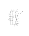
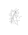
図2〜図5に示すゲート50は、タブレット排出部46に配置されている。ゲート50は、第1の排出チャネル52と第2の排出チャネル54とを有する。第1の排出チャネル52と第2の排出チャネル54は、隔壁56によって互いに隔てられている。隔壁56内に配置された第1のゲートフラップ58は、図2に示す第1の切換位置と、ゲートフラップ58の自由端62が第2の排出チャネル54の反対側の壁64に対して当接する第2の切換位置(図示せず)との間で第1の枢動軸60を中心に枢動自在に取り付けられている。図2〜図5では、タブレットはゲート50を通って上から下へ流れる。第1のゲートフラップ58の下流では、第2のゲートフラップ66が、図2に示す第1の切換位置と図4に示す第2の切換位置との間の第2の排出チャネル54内で第2の枢動軸68を中心に枢動自在に取り付けられる。第2のゲートフラップ66の下流には、第3の排出チャネル72を画定する隔壁70が見られる。第1のゲートフラップ58および第2のゲートフラップ66をそれらのそれぞれの第1および第2の切換位置の間で枢動させるために、電気モータまたは電磁駆動装置などの駆動装置の駆動部が設けられている。さらに、ゲートフラップ58、66のそれぞれの端部位置、すなわちそれぞれの第1の切換位置およびそれぞれの第2の切換位置の到達を検出する、それ自体既知のセンサ(図示せず)を設けることができる。図示の例では、センサの検出信号も制御装置48に印加することができる。
The
ゲート50の異なる動作状態に対してゲート50を介して排出されるタブレット74を図3〜図5に示す。図3に見られるように、タブレット74は、第1のゲートフラップ58および第2のゲートフラップ66が第1の切換位置にあるときに第2の排出チャネル54を横切る。対照的に、図4に示すように第1のゲートフラップ58がその第2の切換位置に向かって移動すると、タブレット74の流れは、第2の排出チャネル54から第1の排出チャネル52内に偏向される。第1のゲートフラップ58がその第1の切換位置にあるときだけ、タブレット74の流れは第2のゲートフラップ66に到達する。その切換位置に応じて、これはタブレット74の流れを第3の排出チャネル72(図5参照)へと偏向させるか、またはタブレット74の流れが第2の排出チャネル54を通って流れ続けることができるように第3の排出チャネル72へのアクセスを閉じる。
The
第2の排出チャネル54は、例えば、良好なタブレット用のタブレット排出口に通じ得る。第3の排出チャネル72は、例えばサンプリング用のタブレット排出口に通じ得る。第1の排出チャネル52は、例えば、不良タブレット用のタブレット排出口に通じ得る。
The
図4では、第1のゲートフラップ58と反対側の壁64との間でクランプされたタブレット76を見ることができる。それ故に、第1のゲートフラップ58は、その第2の切替位置に到達することができない。第2の切換位置に到達しなかったことは、それぞれのセンサによって検出され、そのため制御装置は、切替信号を第1のゲートフラップ58の装置に発信する。それにより、制御装置は、第1の切替位置に向かって、すなわち、図4において反時計回りに引き返すように第1のゲートフラップ58を部分的に駆動させる。クランプされたタブレット76は、それによって開放され、流れ続けることができる。これを達成するために、ゲートフラップ58のわずかな戻り移動が、タブレット76が開放されるためには十分である。次いで、制御装置は、第1のゲートフラップ58が今やタブレット76が開放されたために容易に達することができる第2の切替位置に戻るように、再度これに対応する切替信号を出力して装置を制御する。
In FIG. 4, a
図5では、第2のゲートフラップ66が、その第1の切替位置からその第2の切替位置に移動するとき、それ自体と反対側の隔壁56との間でタブレット78をクランプさせる実例を示している。やはりこの場合も、第2のゲートフラップ66は、その第2の切替位置に到達することができない。関連するセンサの関連する検出信号、またはそれぞれその不在に起因して、制御装置48は、切替信号を第2のゲートフラップ66の装置に出力する。それにより、制御装置48は、第2のゲートフラップ66を部分的にその第1の切替信号に向かって、すなわち、図5において時計回りに戻す。クランプされたタブレット78は、そのために開放され、流れることができる。やはりこの場合も、ゲートフラップ66のわずかな戻り移動が、タブレット78が開放されるには十分である。次いで、第2のゲートフラップ66は、制御装置48からのそれに対応する切替信号によりその第2の切替位置に戻り、今やそれに完全に到達することができる。
FIG. 5 shows an example in which the
第2の排出チャネル54は、その枢動運動中に第1のゲートフラップ58が通過する領域、特にその自由端62が通過する領域のすぐ上流の両側で幅が拡張することが、図2〜図5からも分かる。拡張セクションは、符号80および82で示されている。これに関連して、壁突出部84からの上流側狭窄部が仕切るので、拡張セクション82が形成されていることが認識できる。図示された例において段階的に拡張するセクション80、82はそれぞれ、図示された例においてゲート50によってそらされるタブレット74、76の幅に実質的に対応する。例えば、図4において拡張セクション80が示されているように、これらの拡張セクション80、82は、クランプされたタブレット76およびそれ故に、それぞれのゲートフラップによって到達されなかったそれぞれの端部位置により、タブレット74の流れが損なわれないようする。そのために、クランプされたタブレット76は、すでに拡張セクション80内に位置している。第1のゲートフラップ58の自由端62は、基本的に拡張セクション80のすぐ上流側に位置する壁セクション86を越えて内側に突き出ていない。これに関して、反対側に設けられた拡張セクション82は、同じ機能を提供する。
The
枢動運動中に第2のゲートフラップ66の自由端88が通過する領域からすぐ上流の反対側に、第2の排出チャネル54内の拡張された幅を有するセクション90、92もある。これに関連して、拡張セクション92は、第2の排出チャネル54の狭窄部の第1のゲートフラップ58の端部(図2の下端部)によって形成されている。第1のゲートフラップ58を参照して上述したのと同じ方法で、拡張セクション90、92はまた、タブレット74の流れが損なわれることにより、第2のゲートフラップ66によってタブレット78をクランプさせ、そのために第2のゲートフラップ66をそれぞれの端部位置に到達させることができなくなる。拡張セクション92に関しては、図5に図示されている。拡張セクション90、92はまた、その幅において、ゲート50によってそらされるタブレット74、76の直径に実質的に対応する。
Also on the opposite side, just upstream from the area through which the
10 ダイプレート
12 キャビティ
14 上部パンチ
16 下部パンチ
18 上部制御カム要素
20 下部制御カム要素
22 充填装置
24 充填室
26 充填材料貯蔵器
28 供給セクション
30 プレス装置
32 上部プレプレスローラ
34 下部プレプレスローラ
36 上部メインプレスローラ
38 下部メインプレスローラ
40 排出装置
42 スクレーパ
46 タブレット排出部
48 制御装置
50 ゲート
52 第1の排出チャネル
54 第2の排出チャネル
56 隔壁
58 第1のゲートフラップ
60 第1の駆動軸
62 自由端
64 壁
66 第2のゲートフラップ
68 第2の駆動軸
70 隔壁
72 第3の排出チャネル
74 タブレット
76 タブレット
78 タブレット
80 拡張セクション
82 拡張セクション
84 壁突出部
86 壁セクション
88 自由端
90 拡張セクション
92 拡張セクション
Claims (11)
9. The method according to claim 9, wherein the method is carried out using a gate according to claim 1 or using a rotary tablet press according to claim 8. The method described in.
Applications Claiming Priority (2)
| Application Number | Priority Date | Filing Date | Title |
|---|---|---|---|
| DE102018116202.2 | 2018-07-04 | ||
| DE102018116202.2A DE102018116202B4 (en) | 2018-07-04 | 2018-07-04 | Switch of a tablet outlet of a tablet press and method for operating a switch |
Publications (2)
| Publication Number | Publication Date |
|---|---|
| JP2020006440A true JP2020006440A (en) | 2020-01-16 |
| JP6884817B2 JP6884817B2 (en) | 2021-06-09 |
Family
ID=67003268
Family Applications (1)
| Application Number | Title | Priority Date | Filing Date |
|---|---|---|---|
| JP2019116856A Active JP6884817B2 (en) | 2018-07-04 | 2019-06-25 | Gate for tablet discharge part of tablet press and how to operate the gate |
Country Status (6)
| Country | Link |
|---|---|
| US (1) | US11707435B2 (en) |
| EP (1) | EP3597571B1 (en) |
| JP (1) | JP6884817B2 (en) |
| CN (1) | CN110682583B (en) |
| DE (1) | DE102018116202B4 (en) |
| PL (1) | PL3597571T3 (en) |
Families Citing this family (2)
| Publication number | Priority date | Publication date | Assignee | Title |
|---|---|---|---|---|
| DE102020114369B3 (en) * | 2020-05-28 | 2021-04-29 | Fette Compacting Gmbh | Discharge device for discharging pellets from a rotary press |
| DE102022129223A1 (en) * | 2022-11-04 | 2024-05-08 | Syntegon Technology Gmbh | Discharge chute for a tablet press, a discharge system for a tablet press and a tablet press comprising a corresponding discharge chute or a corresponding discharge system |
Citations (6)
| Publication number | Priority date | Publication date | Assignee | Title |
|---|---|---|---|---|
| JPS6271107U (en) * | 1985-10-22 | 1987-05-07 | ||
| JP2001511708A (en) * | 1997-02-12 | 2001-08-14 | グラクソ、グループ、リミテッド | An improved discharge chute for a tablet tablet press |
| WO2008038070A1 (en) * | 2006-09-29 | 2008-04-03 | Courtoy Nv | A system for rejection of tablets produced in a rotary tablet press and a method of rejection of tablets |
| US20080237097A1 (en) * | 2007-03-31 | 2008-10-02 | Fette Gmbh | Apparatus for the outflow of pressed items from a rotary press |
| JP2011235332A (en) * | 2010-05-12 | 2011-11-24 | Hata Tekkosho:Kk | Device for taking out powder compression molding, and rotary type powder compression molding device equipped therewith |
| KR20140002859A (en) * | 2012-06-28 | 2014-01-09 | 에치엘팜텍 주식회사 | Tablet molding apparatus |
Family Cites Families (10)
| Publication number | Priority date | Publication date | Assignee | Title |
|---|---|---|---|---|
| US3997063A (en) * | 1974-03-21 | 1976-12-14 | Hoffmann-La Roche Inc. | Apparatus for high-speed accurate counting and handling of discrete objects such as tablets |
| JPH10155877A (en) * | 1996-11-26 | 1998-06-16 | Nippon Alum Co Ltd | Tablet transferring device |
| EP1423260B1 (en) * | 2001-09-05 | 2007-01-24 | Courtoy N.V. | A rotary tablet press and a method of cleaning such a press |
| DE102010012327B4 (en) | 2010-03-23 | 2012-02-09 | Fette Compacting Gmbh | tablet outlet |
| KR200473252Y1 (en) | 2012-11-06 | 2014-06-19 | 대성전기공업 주식회사 | Insert molding producing apparatus |
| CN104443593A (en) * | 2014-10-30 | 2015-03-25 | 黑龙江中科诺晟自动化设备开发有限公司 | Implementation method for pressing medicine box of medicine loading mechanism in automated medicine management device |
| CN204278584U (en) * | 2014-11-29 | 2015-04-22 | 山东希尔康泰药业有限公司 | Highspeedrotarytabletpress |
| CN205112500U (en) | 2015-10-30 | 2016-03-30 | 北京新龙立科技有限公司 | Split type fin -outlet mechanism |
| CN206597145U (en) | 2016-08-19 | 2017-10-31 | 深圳市前海康启源科技有限公司 | The healthy helmet with head massage function |
| CN110799327A (en) | 2017-05-03 | 2020-02-14 | 罗马科基利安有限公司 | Rotary tablet press and tablet outlet thereof |
-
2018
- 2018-07-04 DE DE102018116202.2A patent/DE102018116202B4/en active Active
-
2019
- 2019-06-24 PL PL19181953.1T patent/PL3597571T3/en unknown
- 2019-06-24 EP EP19181953.1A patent/EP3597571B1/en active Active
- 2019-06-25 JP JP2019116856A patent/JP6884817B2/en active Active
- 2019-07-01 US US16/458,686 patent/US11707435B2/en active Active
- 2019-07-03 CN CN201910591771.5A patent/CN110682583B/en active Active
Patent Citations (6)
| Publication number | Priority date | Publication date | Assignee | Title |
|---|---|---|---|---|
| JPS6271107U (en) * | 1985-10-22 | 1987-05-07 | ||
| JP2001511708A (en) * | 1997-02-12 | 2001-08-14 | グラクソ、グループ、リミテッド | An improved discharge chute for a tablet tablet press |
| WO2008038070A1 (en) * | 2006-09-29 | 2008-04-03 | Courtoy Nv | A system for rejection of tablets produced in a rotary tablet press and a method of rejection of tablets |
| US20080237097A1 (en) * | 2007-03-31 | 2008-10-02 | Fette Gmbh | Apparatus for the outflow of pressed items from a rotary press |
| JP2011235332A (en) * | 2010-05-12 | 2011-11-24 | Hata Tekkosho:Kk | Device for taking out powder compression molding, and rotary type powder compression molding device equipped therewith |
| KR20140002859A (en) * | 2012-06-28 | 2014-01-09 | 에치엘팜텍 주식회사 | Tablet molding apparatus |
Also Published As
| Publication number | Publication date |
|---|---|
| DE102018116202A1 (en) | 2020-01-09 |
| JP6884817B2 (en) | 2021-06-09 |
| EP3597571B1 (en) | 2022-08-17 |
| CN110682583B (en) | 2021-09-24 |
| US20200009058A1 (en) | 2020-01-09 |
| DE102018116202B4 (en) | 2020-07-23 |
| EP3597571A1 (en) | 2020-01-22 |
| PL3597571T3 (en) | 2023-01-16 |
| US11707435B2 (en) | 2023-07-25 |
| CN110682583A (en) | 2020-01-14 |
Similar Documents
| Publication | Publication Date | Title |
|---|---|---|
| US10322556B2 (en) | Rotary tablet press with tablet outlet, tablet outlet for said rotary tablet press and method for producing tablets on a tablet press | |
| JP2020006439A (en) | Gate for tablet discharge section of tablet press and method of operating gate | |
| JP2020006440A (en) | Gate for tablet discharge part of tablet press and actuation method for gate | |
| US8078329B2 (en) | System for rejection of tablets produced in a rotary tablet press and a method of rejection of tablets | |
| JP2020011298A (en) | Gate of tablet discharge part of tablet press | |
| EP1676779A1 (en) | A device for feeding ordered groups of cigarettes | |
| US20210154959A1 (en) | Rotary tablet press and tablet outlet therefor | |
| KR102152593B1 (en) | Apparatus and method for determining the closing force during capsule closure | |
| CN113733648B (en) | Discharge device for discharging pressed products from a rotary press | |
| JP2010046040A (en) | Cooked rice-molding device and cooked rice-molding method | |
| CN112236292B (en) | Discharge chute for a tablet press and method for sorting tablets after their production in a tablet press | |
| KR20160131285A (en) | Sealing material supply apparatus for duplex type glass | |
| CN111248833B (en) | Prompting method, washing electric appliance and storage medium | |
| US11136203B2 (en) | Material diverter and separator | |
| CN100521903C (en) | Workpiece Conveyor | |
| KR0150695B1 (en) | Package Pusher of Semiconductor Manufacturing Equipment | |
| JP2002144011A (en) | Device for carrying out product in die casting machine | |
| HK1093478B (en) | Apparatus for detecting dropping tablets in automatic medicine packaging machine |
Legal Events
| Date | Code | Title | Description |
|---|---|---|---|
| A621 | Written request for application examination |
Free format text: JAPANESE INTERMEDIATE CODE: A621 Effective date: 20191126 |
|
| A131 | Notification of reasons for refusal |
Free format text: JAPANESE INTERMEDIATE CODE: A131 Effective date: 20200924 |
|
| A601 | Written request for extension of time |
Free format text: JAPANESE INTERMEDIATE CODE: A601 Effective date: 20201223 |
|
| A521 | Request for written amendment filed |
Free format text: JAPANESE INTERMEDIATE CODE: A523 Effective date: 20210121 |
|
| TRDD | Decision of grant or rejection written | ||
| A01 | Written decision to grant a patent or to grant a registration (utility model) |
Free format text: JAPANESE INTERMEDIATE CODE: A01 Effective date: 20210420 |
|
| A61 | First payment of annual fees (during grant procedure) |
Free format text: JAPANESE INTERMEDIATE CODE: A61 Effective date: 20210512 |
|
| R150 | Certificate of patent or registration of utility model |
Ref document number: 6884817 Country of ref document: JP Free format text: JAPANESE INTERMEDIATE CODE: R150 |
|
| R250 | Receipt of annual fees |
Free format text: JAPANESE INTERMEDIATE CODE: R250 |
|
| R250 | Receipt of annual fees |
Free format text: JAPANESE INTERMEDIATE CODE: R250 |
|
| R250 | Receipt of annual fees |
Free format text: JAPANESE INTERMEDIATE CODE: R250 |