JP2020006470A - socket - Google Patents
socket Download PDFInfo
- Publication number
- JP2020006470A JP2020006470A JP2018129092A JP2018129092A JP2020006470A JP 2020006470 A JP2020006470 A JP 2020006470A JP 2018129092 A JP2018129092 A JP 2018129092A JP 2018129092 A JP2018129092 A JP 2018129092A JP 2020006470 A JP2020006470 A JP 2020006470A
- Authority
- JP
- Japan
- Prior art keywords
- socket
- view
- hole
- recess
- apex
- Prior art date
- Legal status (The legal status is an assumption and is not a legal conclusion. Google has not performed a legal analysis and makes no representation as to the accuracy of the status listed.)
- Granted
Links
Images


Classifications
-
- B—PERFORMING OPERATIONS; TRANSPORTING
- B25—HAND TOOLS; PORTABLE POWER-DRIVEN TOOLS; MANIPULATORS
- B25B—TOOLS OR BENCH DEVICES NOT OTHERWISE PROVIDED FOR, FOR FASTENING, CONNECTING, DISENGAGING OR HOLDING
- B25B23/00—Details of, or accessories for, spanners, wrenches, screwdrivers
Landscapes
- Engineering & Computer Science (AREA)
- Mechanical Engineering (AREA)
- Connection Of Batteries Or Terminals (AREA)
- Clamps And Clips (AREA)
- Superconductors And Manufacturing Methods Therefor (AREA)
Abstract
【課題】本発明は、締付時にソケット孔の凹み、特に凹みの頂角の応力割れが生じ難いソケットを提供する。
【解決手段】本発明に係るソケット10は、動力工具の出力軸に装着して使用され、締結部材を締緩するソケットであって、基端に前記出力軸が嵌まる差込角32の形成された取付筒部30、先端側に前記締結部材が嵌まるソケット孔21の形成されたソケット筒部22を具え、前記ソケット孔は、前記ソケット筒部の先端から後退した位置に形成され、外周に向けて膨らんだ複数の凹み22を有しており、前記ソケット筒部の先端には、前記ソケット孔の前記凹みに外接する内径を有する環状の段部28が形成されている。
【選択図】図1An object of the present invention is to provide a socket which is unlikely to cause a stress crack at a recess of a socket hole, in particular, an apex angle of the recess during tightening.
A socket (10) according to the present invention is used by being attached to an output shaft of a power tool, and is a socket for tightening and loosening a fastening member. And a socket tube portion 22 having a socket hole 21 formed at a tip end thereof, into which the fastening member is fitted. The socket has a plurality of recesses 22, and an annular step 28 having an inner diameter circumscribing the recess of the socket hole is formed at the tip of the socket tubular portion.
[Selection diagram] Fig. 1
Description
本発明は、動力工具に装着され、ボルト、ナットなどの締結部材を締緩するソケットに関するものであり、より具体的には、ソケット孔の応力割れを低減できるソケットに関するものである。 The present invention relates to a socket which is mounted on a power tool and tightens and loosens fastening members such as bolts and nuts, and more particularly to a socket which can reduce stress cracking in a socket hole.
ボルトやナットなどの締結部材を締緩する動力工具では、締結部材に合わせたソケットを動力工具の出力軸に装着し、締結部材の締結を行なっている。 In a power tool for fastening a fastening member such as a bolt or a nut, a socket corresponding to the fastening member is mounted on an output shaft of the power tool to fasten the fastening member.
ソケットは、締結部材が嵌まる六角形などの外周に向けて凹みが形成されたソケット孔が形成されている。ソケット孔は、ソケットの端面から面取りなしで形成したり、特許文献1に示すように締結部材を挿入し易くするためにソケットの端面からソケット孔に向けてテーパー形状の面取りを施して形成される。 The socket is formed with a socket hole in which a recess is formed toward the outer periphery of a hexagon or the like into which the fastening member fits. The socket hole is formed without chamfering from the end face of the socket, or is formed by chamfering a tapered shape from the end face of the socket toward the socket hole in order to facilitate insertion of the fastening member as disclosed in Patent Document 1. .
動力工具の高出力や短時間締付のための高速化が進められており、また、締結部材には、より高い締付トルクが求められている。このような状況下において、締付けの際にソケットに割れやヒビが生じることがある。 Higher output and higher speed for short-time tightening of power tools are being promoted, and a higher tightening torque is required for a fastening member. Under such circumstances, the socket may be cracked or cracked during tightening.
割れやヒビの生じたソケットを観察したところ、ソケット孔の外周に膨らんだ凹み、特に凹みに形成された頂角を起点にして割れなどが生じていることがわかった。そして、その原因は、締付時に頂角に応力が集中することによるものであり、凹みの外側、すなわち、ソケットの端面が頂角の外側にあるため、割れやヒビが生じ易いことを解明した。 Observation of the socket with cracks and cracks revealed that a bulge was formed on the outer periphery of the socket hole, and that cracks and the like were generated starting from the apex angle formed in the dent. The cause is that stress concentrates on the apex angle at the time of tightening, and it has been clarified that cracks and cracks are easily generated because the outside of the dent, that is, the end face of the socket is outside the apex angle. .
本発明の目的は、締付時にソケット孔の凹み、特に凹みの頂角の応力割れが生じ難いソケットを提供することである。 SUMMARY OF THE INVENTION An object of the present invention is to provide a socket in which a dent of a socket hole, particularly a stress crack at an apex angle of the dent, does not easily occur during tightening.
上記課題を解決するために、本発明に係るソケットは、
動力工具の出力軸に装着して使用され、締結部材を締緩するソケットであって、
基端に前記出力軸が嵌まる差込角の形成された取付筒部、先端側に前記締結部材が嵌まるソケット孔の形成されたソケット筒部を具え、
前記ソケット孔は、前記ソケット筒部の先端から後退した位置に形成され、外周に向けて膨らんだ複数の凹みを有しており、
前記ソケット筒部の先端には、前記ソケット孔の前記凹みに外接する内径を有する環状の段部が形成されている。
In order to solve the above problems, a socket according to the present invention is:
A socket which is used by being attached to an output shaft of a power tool and tightens and loosens a fastening member,
At the base end, a mounting cylinder portion having an insertion angle at which the output shaft is fitted, a socket cylinder portion having a socket hole at the tip end at which the fastening member is fitted,
The socket hole is formed at a position retracted from the tip of the socket tubular portion, and has a plurality of recesses bulging toward the outer periphery,
An annular step having an inner diameter circumscribing the recess of the socket hole is formed at a tip of the socket tube.
前記凹みは頂角を有し、前記頂角に前記段部が外接していることが望ましい。 It is preferable that the recess has an apex angle, and the step portion circumscribes the apex angle.
前記凹みは、2の頂角を有し、前記頂角と前記各頂角間に存する内周面に前記段部が外接している構成とすることができる。 The recess may have two apex angles, and the step may be circumscribed on an inner peripheral surface between the apex angles and the apex angles.
本発明の動力工具は、上記ソケットを出力軸に装着して構成することができる。 The power tool of the present invention can be configured by mounting the socket on an output shaft.
本発明に係るソケットによれば、ソケット孔は、凹みは環状の段部に外接、すなわち、環状の段部が凹みに内接した構成である。凹み及び凹みの頂角は先行技術の如く端面に設けられたものではなく、段部に連続しているから、応力が集中しても凹みや凹みの頂角を起点とする割れやヒビなどの応力割れを生じ難くすることができる。 According to the socket according to the present invention, the socket hole has a configuration in which the recess circumscribes the annular step, that is, the annular step is inscribed in the recess. The dent and the apex angle of the dent are not provided on the end face as in the prior art, and are continuous with the stepped portion. Therefore, even when stress is concentrated, cracks and cracks starting from the dent or the apex angle of the dent are obtained. Stress cracking can be suppressed.
以下、本発明の一実施形態に係るソケット10について、図面を参照しながら説明を行なう。なお、図は本発明に係るソケット筒部20の構成以外の部分、具体的には取付筒部30を適宜点線で示している。
Hereinafter, a
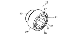
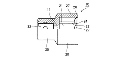
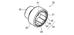
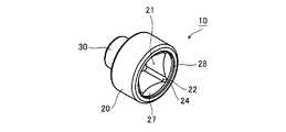
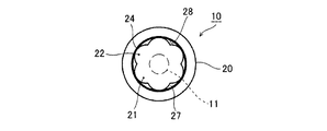
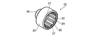
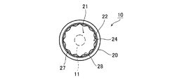
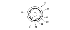
図1は、本発明の第1実施形態に係るソケット10の斜視図、図2は先端側から見た正面図、図3は側面図、図4は一部を断面した側面図、図5は基端側から見た底面図である。また、図6は、図1の丸囲み部Aを拡大した斜視図である。図に示すように、ソケット10は、先端側にボルトやナットなどの締結部材が挿入されるソケット孔21が形成されたソケット筒部20と、基端側に締付機などの動力工具の出力軸が差し込まれる矩形の差込角32が形成された取付筒部30が形成されている。ソケット孔21と差込角32との間は断面略矩形の貫通孔11によって連通している。
FIG. 1 is a perspective view of a
ソケット筒部20に形成されるソケット孔21は、図1、図2、図4及び図6に示すように、締結部材を挿入可能な凹みであって、ソケット筒部20よりも僅かに後退した位置に形成される。図示のソケット孔21は、所謂ダブル六角の一山飛ばし構造であり、外周に向けて膨らんだ断面略台形形状の凹み22が6つ形成されている。凹み22,22間に形成される端面27は、後述する段部28から内向きに突出している。この端面27は、ソケット10の軸心に直交する形状や、図4に示すようにテーパー形状とすることができる。
As shown in FIGS. 1, 2, 4, and 6, the
各凹み22は、角部となる頂角24,24と、頂角24,24間に形成された円弧状の内周面26を有する。頂角24,24と内周面26は、ソケット孔21と同心円に形成されている。
Each of the
そして、本発明のソケット10は、図に示すように、ソケット筒部20の先端に、ソケット孔21よりも先端側に環状の段部28を形成している。段部28は、ソケット筒部20の先端の内周側を拡径した形状であり、頂角24,24と内周面26が外接している。すなわち、図4及び図6に示されるように、段部28は、同心円上に配置された頂角24,24と内周面26の直径と同じ直径であり、頂角24,24及び内周面26と段差なく連続している。
In the
段部28の深さ(ソケット孔21からソケット筒部20の先端までの長さ)は、1mm〜5mmが好適であり、2mm〜3mmが望ましい。
The depth of the step portion 28 (the length from the
然して、本発明のソケット10は、動力工具(図示せず)のドライブ軸を差込角32に挿入し、図6に示すように、締結部材40を挿入した状態で、締付作業を行なう。このとき、締結部材40に加わるトルクに比例した応力Fがソケット10に作用する。そして、その応力Fはソケット孔21の内壁を構成する凹み22のうち、特に頂角24に集中的に作用する。
However, the
本発明のソケット10は、ソケット孔21の凹み22のうち、特に応力割れの起点となりやすい頂角24,24が段部28に外接している。そして、頂角24に応力Fが作用しても、頂角24が段部28と段差なく連続しているから割れやヒビを生じ難くすることができる。
In the
すなわち、段部28に頂角24及び内周面25が外接した構成であるから、頂角24は端面に位置せず、先行技術のような端面がない構成であるから、頂角24が割れやヒビの起点となり難く、割れやヒビの発生を抑えることができる。
That is, since the
図7乃至図32は、本発明のソケット10のソケット孔21の形状を変えた実施形態である。何れもソケット孔21に頂角24が形成されており、当該頂角24がソケット筒部20の先端に段部28に外接している。なお、第1実施形態と同じ符号は、同じ部材又は同等の部材を意味し、適宜説明を省略している。
7 to 32 show an embodiment in which the shape of the
図7乃至図9は、第2実施形態であり、略六角星形の孔形状(所謂E型ヘックスローブ:トルクス(登録商標))のソケット孔21のソケット10である。ソケット孔21の凹み22は円弧状であり、頂角24が段部28に外接している。側面図及び底面図は、第1実施形態の図3及び図5と同じである。
FIGS. 7 to 9 show a second embodiment, in which the
図19乃至図12は、第3実施形態であり、略六角星形の孔(所謂トルクスプラス(登録商標))であって、凹み22の頂角24,24間に円弧状の内周面26が形成されている。頂角24,24及び内周面26が段部28に外接している。側面図及び底面図は、第1実施形態の図3及び図5と同じである。
FIGS. 19 to 12 show a third embodiment, which is a substantially hexagonal star-shaped hole (so-called Torx Plus (registered trademark)), and has an arc-shaped inner
図13乃至図17は、第4実施形態であり、六角形状のソケット孔21を有する。そして、6つの頂角24が段部28に外接している。
13 to 17 show a fourth embodiment, which has a
図18乃至図20は、第5実施形態であり、四角形状のソケット孔21を有し、各頂角24が段部28に外接している。側面図及び底面図は、第4実施形態の図15及び図17と同じである。
FIGS. 18 to 20 show a fifth embodiment, in which a
図21乃至図23は、第6実施形態であり、円弧状の凹み22が螺旋状に形成されたツイストタイプである。各凹み22の円弧状の頂点が頂角24となり、段部28に外接している。側面図及び底面図は、第4実施形態の図15及び図17と同じである。
FIGS. 21 to 23 show a sixth embodiment, which is a twist type in which an arc-shaped
図24乃至図26は、第7実施形態であり、12個の凹み22が形成された12角形状のソケット孔21を有している。各凹み22の頂点が頂角24となり、段部28に外接している。側面図及び底面図は、第4実施形態の図15及び図17と同じである。
FIGS. 24 to 26 show the seventh embodiment, which has a
図27乃至図29は、第8実施形態であり、8つの凹み22が形成された8角形状(所謂ダブル4角)のソケット孔21を有するソケット10である。各凹み22は、2つの頂角24,24を有し、頂角24,24間に円弧状の内周面26を有している。頂角24,24と内周面26は段部28に外接している。側面図及び底面図は、第4実施形態の図15及び図17と同じである。
FIGS. 27 to 29 show an eighth embodiment, which is a
図30乃至図32は、第9実施形態であり、十文字形状の凹み22(所謂フォームタイ(登録商標))が形成されたソケット孔21を有する。各凹み22は、2つの頂角24,24と頂角24,24間に円弧状の内周面26を有している。そして、頂角24,24と内周面26は段部28に外接している。側面図及び底面図は、第4実施形態の図15及び図17と同じである。
30 to 32 show a ninth embodiment, which has a
何れの実施形態も、頂角24、頂角24と内周面26が段部28に外接しており、段差なく繋がっているから、第1実施形態と同様、締付時の応力が作用しても、頂角24に割れやヒビを生じ難くすることができる。
In any of the embodiments, the
そして、上記実施形態のソケット10を装着した動力工具は、締結部材を締め付ける際に、割れやヒビの発生を抑えることができるから、長期に亘って安定した性能を発揮することができる。
The power tool equipped with the
上記説明は、本発明を説明するためのものであって、特許請求の範囲に記載の発明を限定し、或いは範囲を限縮するように解すべきではない。また、本発明の各部構成は、上記実施例に限らず、特許請求の範囲に記載の技術的範囲内で種々の変形が可能であることは勿論である。 The above description is for the purpose of illustrating the present invention, and should not be construed as limiting the invention described in the claims or limiting the scope thereof. In addition, the configuration of each part of the present invention is not limited to the above-described embodiment, and it is needless to say that various modifications can be made within the technical scope described in the claims.
たとえば、ソケット孔21の形状は、一例であり、他の形状とすることができることは勿論である。また、ソケット孔21の内径、差込角32の形状に応じて、ソケット筒部20の直径、取付筒部30の直径は適宜変更できることも理解されるべきである。
For example, the shape of the
10 ソケット
20 ソケット筒部
21 ソケット孔
22 凹み
24 頂角
26 内周面
28 段部
DESCRIPTION OF
Claims (4)
基端に前記出力軸が嵌まる差込角の形成された取付筒部、先端側に前記締結部材が嵌まるソケット孔の形成されたソケット筒部を具え、
前記ソケット孔は、前記ソケット筒部の先端から後退した位置に形成され、外周に向けて膨らんだ複数の凹みを有しており、
前記ソケット筒部の先端には、前記ソケット孔の前記凹みに外接する内径を有する環状の段部が形成されている、
ことを特徴とするソケット。 A socket which is used by being attached to an output shaft of a power tool and tightens and loosens a fastening member,
At the base end, a mounting cylinder portion having an insertion angle at which the output shaft is fitted, a socket cylinder portion having a socket hole at the tip end at which the fastening member is fitted,
The socket hole is formed at a position retracted from the tip of the socket tubular portion, and has a plurality of recesses bulging toward the outer periphery,
An annular step having an inner diameter circumscribing the recess of the socket hole is formed at a tip of the socket tube portion,
A socket characterized by the above.
請求項1に記載のソケット。 The depression has an apex angle, and the step portion circumscribes the apex angle;
The socket according to claim 1.
請求項2に記載のソケット。 The recess has an apex angle of 2, and the step portion circumscribes an inner peripheral surface existing between the apex angle and each of the apex angles,
The socket according to claim 2.
Priority Applications (3)
| Application Number | Priority Date | Filing Date | Title |
|---|---|---|---|
| JP2018129092A JP7201983B2 (en) | 2018-07-06 | 2018-07-06 | socket |
| TW108123775A TWI811393B (en) | 2018-07-06 | 2019-07-05 | sleeve |
| CN201910608886.0A CN110682245B (en) | 2018-07-06 | 2019-07-05 | Socket joint |
Applications Claiming Priority (1)
| Application Number | Priority Date | Filing Date | Title |
|---|---|---|---|
| JP2018129092A JP7201983B2 (en) | 2018-07-06 | 2018-07-06 | socket |
Publications (3)
| Publication Number | Publication Date |
|---|---|
| JP2020006470A true JP2020006470A (en) | 2020-01-16 |
| JP2020006470A5 JP2020006470A5 (en) | 2021-05-06 |
| JP7201983B2 JP7201983B2 (en) | 2023-01-11 |
Family
ID=69108184
Family Applications (1)
| Application Number | Title | Priority Date | Filing Date |
|---|---|---|---|
| JP2018129092A Active JP7201983B2 (en) | 2018-07-06 | 2018-07-06 | socket |
Country Status (3)
| Country | Link |
|---|---|
| JP (1) | JP7201983B2 (en) |
| CN (1) | CN110682245B (en) |
| TW (1) | TWI811393B (en) |
Cited By (2)
| Publication number | Priority date | Publication date | Assignee | Title |
|---|---|---|---|---|
| TWI792652B (en) * | 2020-12-17 | 2023-02-11 | 日商京都機械工具股份有限公司 | locking tool |
| JP7649197B2 (en) | 2021-05-28 | 2025-03-19 | 日東精工株式会社 | Box bit and automatic fastening machine equipped with the same |
Families Citing this family (2)
| Publication number | Priority date | Publication date | Assignee | Title |
|---|---|---|---|---|
| TWI802299B (en) * | 2022-02-25 | 2023-05-11 | 吳東霖 | Two-way ratchet wrench structure with pawl |
| TWI906094B (en) * | 2024-02-06 | 2025-11-21 | 優鋼機械股份有限公司 | Socket structure |
Citations (8)
| Publication number | Priority date | Publication date | Assignee | Title |
|---|---|---|---|---|
| JPS5343600U (en) * | 1976-09-18 | 1978-04-14 | ||
| JPS5694277U (en) * | 1979-12-17 | 1981-07-27 | ||
| JPS5836074U (en) * | 1981-09-03 | 1983-03-09 | リズム自動車部品製造株式会社 | Work tools |
| JPH0239874U (en) * | 1988-09-07 | 1990-03-16 | ||
| JPH0650759U (en) * | 1992-01-11 | 1994-07-12 | 株式会社山崎歯車製作所 | Wrench socket |
| JPH079356A (en) * | 1993-06-30 | 1995-01-13 | Yutani:Kk | Nut runner |
| US20070084314A1 (en) * | 2005-10-18 | 2007-04-19 | Brian Harker | Socket wrench apparatus |
| JP2016147334A (en) * | 2015-02-10 | 2016-08-18 | トヨタ自動車株式会社 | Bolt tightening device and socket |
Family Cites Families (20)
| Publication number | Priority date | Publication date | Assignee | Title |
|---|---|---|---|---|
| CS157380B1 (en) * | 1972-08-07 | 1974-09-16 | ||
| US4882957A (en) * | 1988-12-16 | 1989-11-28 | Wright Tool Company | Socket wrench opening |
| JP2564473B2 (en) * | 1994-11-11 | 1996-12-18 | 東日本旅客鉄道株式会社 | Double nut socket |
| TW339006U (en) * | 1996-04-16 | 1998-08-21 | zhi-qing Xie | Improved structure of inner hexagonal and duodegonal sleeves addition (1) |
| TW468538U (en) * | 2001-05-29 | 2001-12-11 | Stanley Chiro Int Ltd | Improved socket |
| US6736580B2 (en) * | 2002-01-16 | 2004-05-18 | Hi-Shear Corporation | Lobed drive for hi-lite fastener |
| US7311022B2 (en) * | 2004-08-16 | 2007-12-25 | Snap-On Incorporated | Retention socket |
| US7228764B1 (en) * | 2005-12-31 | 2007-06-12 | Proprietary Technologies, Inc. | Maximum engagement wrench |
| TWM306917U (en) * | 2006-08-04 | 2007-03-01 | Jia-Hua Chen | Improved bush structure |
| TWM323375U (en) * | 2007-07-04 | 2007-12-11 | Leader Union Entpr Co Ltd | Reversible and steady force-application anti-skid socket |
| TWM340147U (en) * | 2008-01-10 | 2008-09-11 | jin-shun Zheng | Improved sleeve structure |
| TWM365236U (en) * | 2009-03-19 | 2009-09-21 | shi-yi Huang | Structural improvement of sleeve for damaged nut |
| TWM371060U (en) * | 2009-05-26 | 2009-12-21 | jin-shun Zheng | Detent structure for socket |
| TWM386962U (en) * | 2010-03-10 | 2010-08-21 | Plus Craft Ind Co Ltd | Socket tool |
| TW201317086A (en) * | 2011-10-26 | 2013-05-01 | Perry James Richardson | Dual hex pattern wrench |
| TWM444246U (en) * | 2012-08-31 | 2013-01-01 | Asti Entpr Co Ltd | Transmissive sleeve structure |
| DE102013015506A1 (en) * | 2013-09-19 | 2015-03-19 | Wera-Werk Hermann Werner Gmbh & Co. Kg | socket |
| US20160318160A1 (en) * | 2015-04-28 | 2016-11-03 | Charlie R. Hon | Double shulder female socket and method for optimizing a torque transmitting relation between a socket wrench and a double shouldered nut |
| TWM530213U (en) * | 2016-06-20 | 2016-10-11 | Chia-Szu Lin | Socket capable of being stably taken and held |
| TWM558688U (en) * | 2017-12-14 | 2018-04-21 | Zhang Man Ji | Socket structure |
-
2018
- 2018-07-06 JP JP2018129092A patent/JP7201983B2/en active Active
-
2019
- 2019-07-05 TW TW108123775A patent/TWI811393B/en active
- 2019-07-05 CN CN201910608886.0A patent/CN110682245B/en active Active
Patent Citations (8)
| Publication number | Priority date | Publication date | Assignee | Title |
|---|---|---|---|---|
| JPS5343600U (en) * | 1976-09-18 | 1978-04-14 | ||
| JPS5694277U (en) * | 1979-12-17 | 1981-07-27 | ||
| JPS5836074U (en) * | 1981-09-03 | 1983-03-09 | リズム自動車部品製造株式会社 | Work tools |
| JPH0239874U (en) * | 1988-09-07 | 1990-03-16 | ||
| JPH0650759U (en) * | 1992-01-11 | 1994-07-12 | 株式会社山崎歯車製作所 | Wrench socket |
| JPH079356A (en) * | 1993-06-30 | 1995-01-13 | Yutani:Kk | Nut runner |
| US20070084314A1 (en) * | 2005-10-18 | 2007-04-19 | Brian Harker | Socket wrench apparatus |
| JP2016147334A (en) * | 2015-02-10 | 2016-08-18 | トヨタ自動車株式会社 | Bolt tightening device and socket |
Cited By (2)
| Publication number | Priority date | Publication date | Assignee | Title |
|---|---|---|---|---|
| TWI792652B (en) * | 2020-12-17 | 2023-02-11 | 日商京都機械工具股份有限公司 | locking tool |
| JP7649197B2 (en) | 2021-05-28 | 2025-03-19 | 日東精工株式会社 | Box bit and automatic fastening machine equipped with the same |
Also Published As
| Publication number | Publication date |
|---|---|
| JP7201983B2 (en) | 2023-01-11 |
| TWI811393B (en) | 2023-08-11 |
| CN110682245B (en) | 2023-03-03 |
| CN110682245A (en) | 2020-01-14 |
| TW202012113A (en) | 2020-04-01 |
Similar Documents
| Publication | Publication Date | Title |
|---|---|---|
| JP2020006470A (en) | socket | |
| TWI696521B (en) | Socket drive improvement | |
| TWI773735B (en) | Multi-directional driver bit | |
| US6609867B2 (en) | Anti-loosening nut assembly | |
| US12162120B2 (en) | Socket drive improvement | |
| JP2013185704A (en) | Lock nut | |
| TWI714439B (en) | Driving head structure of socket wrench | |
| JP6118852B2 (en) | screw | |
| CA1257487A (en) | Box end wrench | |
| TW202042978A (en) | Multi-grip socket bit | |
| JP2009008128A (en) | bolt | |
| CN201763747U (en) | screw | |
| KR20080090594A (en) | Small screw | |
| JP6263691B1 (en) | Locking nut | |
| JP2002364619A (en) | Screw parts and screw part fastening tools | |
| JP3149822U (en) | Fastening bracket | |
| JP2014176946A (en) | Tool socket | |
| CN215548243U (en) | Sleeve structure of nut wrench | |
| JPS5934735Y2 (en) | Structure of bolts and nuts | |
| CN218408114U (en) | Cone ball twisting-off type anti-dismounting nut | |
| JPH0953620A (en) | Tapping screw | |
| JP2021183865A (en) | Lock nut | |
| CN116241541A (en) | Stealthy fastener that comprises angle groove type nut and bolt | |
| JPH08323638A (en) | Crank cap driver for bicycle | |
| JP2002061621A (en) | Log fastening bolt for log house |
Legal Events
| Date | Code | Title | Description |
|---|---|---|---|
| A521 | Request for written amendment filed |
Free format text: JAPANESE INTERMEDIATE CODE: A523 Effective date: 20210317 |
|
| A621 | Written request for application examination |
Free format text: JAPANESE INTERMEDIATE CODE: A621 Effective date: 20210317 |
|
| A977 | Report on retrieval |
Free format text: JAPANESE INTERMEDIATE CODE: A971007 Effective date: 20211027 |
|
| A131 | Notification of reasons for refusal |
Free format text: JAPANESE INTERMEDIATE CODE: A131 Effective date: 20211102 |
|
| A521 | Request for written amendment filed |
Free format text: JAPANESE INTERMEDIATE CODE: A523 Effective date: 20220104 |
|
| A131 | Notification of reasons for refusal |
Free format text: JAPANESE INTERMEDIATE CODE: A131 Effective date: 20220531 |
|
| A521 | Request for written amendment filed |
Free format text: JAPANESE INTERMEDIATE CODE: A523 Effective date: 20220728 |
|
| TRDD | Decision of grant or rejection written | ||
| A01 | Written decision to grant a patent or to grant a registration (utility model) |
Free format text: JAPANESE INTERMEDIATE CODE: A01 Effective date: 20221213 |
|
| A61 | First payment of annual fees (during grant procedure) |
Free format text: JAPANESE INTERMEDIATE CODE: A61 Effective date: 20221216 |
|
| R150 | Certificate of patent or registration of utility model |
Ref document number: 7201983 Country of ref document: JP Free format text: JAPANESE INTERMEDIATE CODE: R150 |
|
| R250 | Receipt of annual fees |
Free format text: JAPANESE INTERMEDIATE CODE: R250 |