JP2020006842A - Pneumatic tire - Google Patents
Pneumatic tire Download PDFInfo
- Publication number
- JP2020006842A JP2020006842A JP2018130351A JP2018130351A JP2020006842A JP 2020006842 A JP2020006842 A JP 2020006842A JP 2018130351 A JP2018130351 A JP 2018130351A JP 2018130351 A JP2018130351 A JP 2018130351A JP 2020006842 A JP2020006842 A JP 2020006842A
- Authority
- JP
- Japan
- Prior art keywords
- tire
- pneumatic tire
- filler
- bead
- height
- Prior art date
- Legal status (The legal status is an assumption and is not a legal conclusion. Google has not performed a legal analysis and makes no representation as to the accuracy of the status listed.)
- Granted
Links
Images


Landscapes
- Tires In General (AREA)
Abstract
【課題】耐摩耗性と操縦安定性を改善し、荒れた路面を走行する際に車両に伝わる振動の減衰性を高めることを可能にした空気入りタイヤを提供する。【解決手段】ビードフィラー6のタイヤ径方向の高さDfがタイヤ断面高さSHに対して0.18≦Df/SH≦0.50の関係を満足し、ビードフィラーのゴム組成物のJIS−A硬度HSfが80≦HSf<100の範囲にあり、230kPaの空気圧を充填し、規格にて定められた最大負荷能力の40%,75%,100%に対応する荷重W40,W75,W100(kN)を負荷した条件にて測定されるコーナリングパワーCP40,CP75,CP100(kN/°)、偏平比R、外径をD(mm)、断面幅の呼びA(mm)について、0.05≦(R×D/2A)2×[(CP100−CP75)/(W100−W75)]/[(CP75−CP40)/(W75−W40)]≦0.50の関係を満足する空気入りタイヤ。【選択図】図1A pneumatic tire is provided which has improved wear resistance and steering stability, and which can enhance damping of vibrations transmitted to a vehicle when traveling on a rough road surface. The height Df of the bead filler 6 in the tire radial direction satisfies the relationship of 0.18≦Df/SH≦0.50 with respect to the tire cross-section height SH, and the rubber composition of the bead filler is JIS- Loads W40, W75, W100 (kN ), cornering power CP40, CP75, CP100 (kN/°), aspect ratio R, outer diameter D (mm), nominal cross-sectional width A (mm), 0.05 ≤ ( RxD/2A)2x[(CP100-CP75)/(W100-W75)]/[(CP75-CP40)/(W75-W40)]≤0.50. [Selection drawing] Fig. 1
Description
本発明は、ビード部にビードコアとビードフィラーを備えた空気入りタイヤに関し、更に詳しくは、耐摩耗性を改善すると共に、操縦安定性のリニアリティを改善し、更には、荒れた路面を走行する際に車両に伝わる振動の減衰性を高めることを可能にした空気入りタイヤに関する。 The present invention relates to a pneumatic tire provided with a bead core and a bead filler in a bead portion, and more specifically, to improve abrasion resistance, improve linearity of steering stability, and further, when traveling on a rough road surface. The present invention relates to a pneumatic tire capable of increasing the damping of vibration transmitted to a vehicle.
空気入りタイヤは、一般に、一対のビード部間に装架されたカーカス層と、トレッド部におけるカーカス層のタイヤ径方向外側に配置された複数層のベルト層と、ビード部の各々に配置されたビードコアと、該ビードコアのタイヤ径方向外側に配置されたビードフィラーとを備えている。 A pneumatic tire is generally disposed on each of a carcass layer mounted between a pair of bead portions, a plurality of belt layers disposed radially outside the carcass layer in the tread portion, and a bead portion. The vehicle includes a bead core and a bead filler disposed outside the bead core in the tire radial direction.
このような空気入りタイヤにおいて、耐摩耗性を改善するために、ベルト層を含むベルト部の剛性を高くする手法が提案されている。しかしながら、このような手法を採用した場合、高荷重域でのコーナリングパワーが増大し、操縦安定性のリニアリティが悪化するという問題がある。つまり、ハンドル操舵の初期に比べて中盤から後半にかけてコーナリングパワーが増大して車両の動きが過敏になるような走行状態は、操縦安定性のリニアリティ(線形感)が良好ではない。そのため、操縦安定性のリニアリティが良好になるようなチューニングが求められている(例えば、特許文献1参照)。 In such a pneumatic tire, a technique for increasing the rigidity of a belt portion including a belt layer has been proposed to improve wear resistance. However, when such a method is adopted, there is a problem that the cornering power in a high load range increases, and the linearity of steering stability deteriorates. In other words, in a running state in which the cornering power increases from the middle to the second half of the steering compared to the initial stage of steering and the movement of the vehicle becomes excessive, the linearity of steering stability is not good. Therefore, tuning is required to improve the linearity of the steering stability (for example, see Patent Document 1).
これに対して、低荷重域のコーナリングパワーを高めることで操縦安定性を改善することが提案されている(例えば、特許文献2,3参照)。しかしながら、低荷重域のコーナリングパワーを高めるだけでは、操縦安定性のリニアリティの改善要求に対して十分に応えることができないのが現状である。
On the other hand, it has been proposed to improve the steering stability by increasing the cornering power in a low load range (for example, see
本発明の目的は、耐摩耗性を改善すると共に、操縦安定性のリニアリティを改善し、更には、荒れた路面を走行する際に車両に伝わる振動の減衰性を高めることを可能にした空気入りタイヤを提供することにある。 An object of the present invention is to improve the abrasion resistance, improve the linearity of steering stability, and further increase the damping of vibration transmitted to a vehicle when traveling on a rough road surface. To provide tires.
上記目的を達成するための本発明の空気入りタイヤは、タイヤ周方向に延在して環状をなすトレッド部と、該トレッド部の両側に配置された一対のサイドウォール部と、これらサイドウォール部のタイヤ径方向内側に配置された一対のビード部と、前記一対のビード部間に装架されたカーカス層と、前記トレッド部におけるカーカス層のタイヤ径方向外側に配置された複数層のベルト層と、前記ビード部の各々に配置されたビードコアと、該ビードコアのタイヤ径方向外側に配置されたビードフィラーとを備えた空気入りタイヤにおいて、
前記ビードフィラーのタイヤ径方向の高さDfが前記空気入りタイヤの断面高さSHに対して0.18≦Df/SH≦0.50の関係を満足し、前記ビードフィラーを構成するゴム組成物のJIS−A硬度HSfが80≦HSf<100の範囲にあり、
規格にて定められた最大負荷能力の40%,75%,100%に対応する荷重をそれぞれW40,W75,W100(kN)とし、前記空気入りタイヤに230kPaの空気圧を充填し、前記荷重W40,W75,W100を負荷した条件にて測定されるコーナリングパワーをそれぞれCP40,CP75,CP100(kN/°)とし、前記空気入りタイヤの偏平比をRとし、その外径をD(mm)とし、その断面幅の呼びをA(mm)としたとき、前記荷重W40,W75,W100及び前記コーナリングパワーCP40,CP75,CP100が0.05≦(R×D/2A)2×[(CP100−CP75)/(W100−W75)]/[(CP75−CP40)/(W75−W40)]≦0.50の関係を満足することを特徴とするものである。
In order to achieve the above object, a pneumatic tire of the present invention includes a ring-shaped tread portion extending in the tire circumferential direction, a pair of sidewall portions disposed on both sides of the tread portion, and these sidewall portions. A pair of bead portions disposed inside the tire radial direction, a carcass layer mounted between the pair of bead portions, and a plurality of belt layers disposed outside the carcass layer in the tread portion in the tire radial direction. And a bead core disposed in each of the bead portions, and a pneumatic tire including a bead filler disposed radially outward of the bead core,
A rubber composition constituting the bead filler, wherein a height Df of the bead filler in the tire radial direction satisfies a relationship of 0.18 ≦ Df / SH ≦ 0.50 with respect to a cross-sectional height SH of the pneumatic tire. JIS-A hardness HSf is in the range of 80 ≦ HSf <100,
Loads corresponding to 40%, 75%, and 100% of the maximum load capacity defined by the standard are W40, W75, and W100 (kN), respectively. The pneumatic tire is filled with an air pressure of 230 kPa, and The cornering power measured under the condition of loading W75 and W100 is CP40, CP75 and CP100 (kN / °), the flatness ratio of the pneumatic tire is R, and the outer diameter is D (mm). When the nominal of the sectional width is A (mm), the load W40, W75, W100 and the cornering power CP40, CP75, CP100 are 0.05 ≦ (R × D / 2A) 2 × [(CP100−CP75) / (W100-W75)] / [(CP75-CP40) / (W75-W40)] ≦ 0.50. It is.
本発明では、ビードフィラーのタイヤ径方向の高さDfを空気入りタイヤの断面高さSHに対して0.18≦Df/SH≦0.50の関係とし、ビードフィラーを構成するゴム組成物のJIS−A硬度HSfを80≦HSf<100の範囲にすることにより、サイドウォール部の剛性を高めて旋回時のトレッド部の滑りを抑制し、耐摩耗性を改善することができる。そして、サイドウォール部の剛性に基づいて耐摩耗性を改善するので、ベルト層を含むベルト部の剛性を高める場合とは異なって、高荷重域でのコーナリングパワーの過度の増大を抑制することができる。更に、荷重W40,W75,W100及びコーナリングパワーCP40,CP75,CP100が0.05≦(R×D/2A)2×[(CP100−CP75)/(W100−W75)]/[(CP75−CP40)/(W75−W40)]≦0.50の関係を満足することにより、高荷重域のコーナリングパワーの過度の増大を抑制することができる。これにより、荷重の増大に伴って適度なコーナリングパワーが発揮されるので、操縦安定性のリニアリティを改善することができる。特に、タイヤサイズによりコーナリングパワーの出易さが異なるため、上記関係式は(R×D/2A)2の値により補正されている。つまり、偏平比が低く、断面幅の呼びに対する外径の比が小さいタイヤほど高荷重側のコーナリングパワーの寄与を低下させるのである。また、上述のようにサイドウォール部の剛性を高めた場合、荒れた路面を走行する際に車両に伝わる振動の減衰性を高めることができ、所謂乗心地のブルブル感を良化することができる。 In the present invention, the height Df in the tire radial direction of the bead filler is set to a relationship of 0.18 ≦ Df / SH ≦ 0.50 with respect to the cross-sectional height SH of the pneumatic tire, and the rubber composition constituting the bead filler is used. By setting the JIS-A hardness HSf in the range of 80 ≦ HSf <100, the rigidity of the sidewall portion is increased, the slip of the tread portion during turning is suppressed, and the wear resistance can be improved. And, since the wear resistance is improved based on the rigidity of the sidewall portion, unlike the case of increasing the rigidity of the belt portion including the belt layer, it is possible to suppress an excessive increase in the cornering power in a high load region. it can. Further, when the loads W40, W75, W100 and the cornering powers CP40, CP75, CP100 are 0.05 ≦ (R × D / 2A) 2 × [(CP100-CP75) / (W100-W75)] / [(CP75-CP40) /(W75-W40)]≦0.50, it is possible to suppress an excessive increase in cornering power in a high load range. As a result, an appropriate cornering power is exhibited as the load increases, so that the linearity of the steering stability can be improved. Particularly, since the easiness of the cornering power varies depending on the tire size, the above relational expression is corrected by the value of (R × D / 2A) 2 . In other words, a tire having a lower aspect ratio and a smaller ratio of the outer diameter to the nominal sectional width reduces the contribution of the cornering power on the high load side. Further, when the rigidity of the sidewall portion is increased as described above, it is possible to increase the damping of vibration transmitted to the vehicle when traveling on a rough road surface, and to improve the so-called riding comfort. .
本発明において、ベルト層のタイヤ周方向に対するコード角度θが18°≦θ≦34°の範囲にあることが好ましい。ベルト層のコード角度θを小さくするとベルト層の剛性が大きくなる傾向があるが、ベルト層の剛性が過度に大きくならない範囲において、サイドウォール部の剛性を増加させることで、操縦安定性のリニアリティを効果的に改善することができる。なお、ベルト層の剛性が低過ぎると、ドレッド部とサイドウォール部との剛性バランスが崩れ易くなる。 In the present invention, the cord angle θ of the belt layer with respect to the tire circumferential direction is preferably in the range of 18 ° ≦ θ ≦ 34 °. When the cord angle θ of the belt layer is reduced, the rigidity of the belt layer tends to increase.However, as long as the rigidity of the belt layer does not become excessively large, the rigidity of the sidewall portion is increased to improve the linearity of the steering stability. It can be improved effectively. If the rigidity of the belt layer is too low, the rigidity balance between the dread portion and the sidewall portion tends to be lost.
ビードフィラーを構成するゴム組成物の20℃における貯蔵弾性率E′は70MPa≦E′≦130MPaの範囲にあることが好ましい。ビードフィラーを構成するゴム組成物の貯蔵弾性率E′を上記範囲に設定することにより、振動減衰性を高めることができる。 The storage elastic modulus E ′ at 20 ° C. of the rubber composition constituting the bead filler is preferably in the range of 70 MPa ≦ E ′ ≦ 130 MPa. By setting the storage elastic modulus E 'of the rubber composition constituting the bead filler within the above range, the vibration damping property can be enhanced.
ビードフィラーの高さDfの中間位置におけるビードフィラーのタイヤ幅方向の厚さWhとビードフィラーの高さDfの中間位置におけるサイドウォール部のタイヤ幅方向の総厚さWtは0.35≦Wh/Wt≦0.80の関係を満足することが好ましい。剛性が高いビードフィラーがサイドウォール部に占める割合を高くすることにより、サイドウォール部の剛性を効果的に増大させることができ、その結果、耐摩耗性や振動減衰性を改善することができる。 The thickness Wh of the bead filler in the width direction of the tire at an intermediate position of the height Df of the bead filler and the total thickness Wt of the sidewall portion in the width direction of the tire at an intermediate position of the height Df of the bead filler are 0.35 ≦ Wh / It is preferable to satisfy the relationship of Wt ≦ 0.80. By increasing the ratio of the bead filler having high rigidity to the side wall portion, the rigidity of the side wall portion can be effectively increased, and as a result, abrasion resistance and vibration damping property can be improved.
カーカス層の巻き上げ高さDpはDf<Dp<SHかつ5mm≦Dp−Dfの関係を満足することが好ましい。カーカス層の巻き上げ高さDpをビードフィラーの高さDfよりも大きくすることにより、サイドウォール部の剛性を効果的に増大させることができ、その結果、耐摩耗性や振動減衰性を改善することができる。また、Dp−Dfの値を十分に確保することで、応力集中を回避してタイヤ故障を抑制することができる。 The winding height Dp of the carcass layer preferably satisfies the relationship of Df <Dp <SH and 5 mm ≦ Dp−Df. By making the winding height Dp of the carcass layer larger than the height Df of the bead filler, the rigidity of the sidewall portion can be effectively increased, and as a result, wear resistance and vibration damping properties are improved. Can be. In addition, by ensuring a sufficient value of Dp-Df, it is possible to avoid stress concentration and suppress tire failure.
ビードフィラーのタイヤ径方向外側には第2フィラーが設けられており、該第2フィラーを構成するゴム組成物のJIS−A硬度HS2が70≦HS2<90かつHS2≦HSfの関係を満足することが好ましい。第2フィラーを追加することにより、サイドウォール部の剛性を効果的に増大させることができ、その結果、耐摩耗性や振動減衰性を改善することができる。第2フィラーのゴム組成物のJIS−A硬度HS2をビードフィラーのゴム組成物のJIS−A硬度HSfよりも小さくすることで、サイドウォール部の剛性を効果的に増大させる一方で、高荷重域のコーナリングパワーの過度の増大を抑制することができる。 A second filler is provided on the outer side of the bead filler in the tire radial direction, and the rubber composition constituting the second filler has a JIS-A hardness HS2 satisfying a relationship of 70 ≦ HS2 <90 and HS2 ≦ HSf. Is preferred. By adding the second filler, the rigidity of the sidewall portion can be effectively increased, and as a result, the wear resistance and the vibration damping property can be improved. By making the JIS-A hardness HS2 of the rubber composition of the second filler smaller than the JIS-A hardness HSf of the rubber composition of the bead filler, the rigidity of the sidewall portion is effectively increased, while the high load range is maintained. Excessive increase in cornering power can be suppressed.
第2フィラーの下端のタイヤ径方向の高さD2L及び第2フィラーの上端のタイヤ径方向の高さD2UはD2L<Df<D2U<0.80×SHかつ0.1×Df≦Df−D2L≦0.5×Dfの関係を満足することが好ましい。第2フィラーをビードフィラーに対してタイヤ径方向に重複させることにより、サイドウォール部の剛性を効果的に増大させることができ、その結果、耐摩耗性や振動減衰性を改善することができる。また、Df−D2Lの値を十分に確保することで、応力集中を回避してタイヤ故障を抑制することができる。更に、第2フィラーの上端のタイヤ径方向の高さD2Uを空気入りタイヤの断面高さSHに対して十分に小さくすることにより、コーナリングパワーのバランスを最適化することができる。 The height D2L of the lower end of the second filler in the tire radial direction and the height D2U of the upper end of the second filler in the tire radial direction are D2L <Df <D2U <0.80 × SH and 0.1 × Df ≦ Df−D2L ≦ It is preferable to satisfy the relationship of 0.5 × Df. By overlapping the second filler with the bead filler in the tire radial direction, the rigidity of the sidewall portion can be effectively increased, and as a result, the wear resistance and the vibration damping property can be improved. Also, by ensuring a sufficient value of Df-D2L, stress concentration can be avoided and tire failure can be suppressed. Further, by making the height D2U of the upper end of the second filler in the tire radial direction sufficiently smaller than the cross-sectional height SH of the pneumatic tire, the cornering power balance can be optimized.
サイドウォール部においてカーカス層の外側に配置されるサイドゴム層を構成するゴム組成物のJIS−A硬度HSsは55≦HSs<80≦HSfの関係を満足することが好ましい。サイドゴム層を構成するゴム組成物のJIS−A硬度HSsを比較的高くすることにより、サイドウォール部の剛性を効果的に増大させることができ、その結果、耐摩耗性や振動減衰性を改善することができる。また、サイドゴム層のゴム組成物のJIS−A硬度HSsをビードフィラーのゴム組成物のJIS−A硬度Hsfよりも低くすることで、高荷重域のコーナリングパワーの過度の増大を抑制することができる。 The JIS-A hardness HSs of the rubber composition constituting the side rubber layer disposed outside the carcass layer in the side wall portion preferably satisfies the relationship of 55 ≦ HSs <80 ≦ HSf. By making the JIS-A hardness HSs of the rubber composition constituting the side rubber layer relatively high, the rigidity of the sidewall portion can be effectively increased, and as a result, wear resistance and vibration damping properties are improved. be able to. Also, by making the JIS-A hardness HSs of the rubber composition of the side rubber layer lower than the JIS-A hardness Hsf of the rubber composition of the bead filler, it is possible to suppress an excessive increase in cornering power in a high load region. .
本発明において、空気入りタイヤに230kPaの空気圧を充填し、規格にて定められた最大負荷能力のそれぞれ40%,75%,100%の荷重を負荷した条件にて接地した際のタイヤ周方向の最大接地長をそれぞれLA1,LB1,LC1とし、タイヤ幅方向の最大接地幅をそれぞれWA1,WB1,WC1とし、タイヤ中心位置からタイヤ幅方向外側に向かって最大接地幅WA1,WB1,WC1の40%の位置におけるタイヤ周方向の外部接地長をそれぞれLA2,LB2,LC2としたとき、最大接地長LA1,LB1,LC1及び前記外部接地長LA2,LB2,LC2が1.02≦(LB2/LB1)/(LA2/LA1)≦1.25、1.00≦(LC2/LC1)/(LB2/LB1)≦1.20、0.75≦LB2/LB1≦1.00の関係を満足することが好ましい。このように接地形状の荷重依存性をコントロールすることにより、操縦安定性のリニアリティを更に改善することができる。 In the present invention, the pneumatic tire is filled with an air pressure of 230 kPa, and the tire circumferential direction when the tire is grounded under the conditions of 40%, 75%, and 100% of the maximum load capacity specified by the standard, respectively. The maximum contact lengths are LA1, LB1, and LC1, respectively, and the maximum contact widths in the tire width direction are WA1, WB1, and WC1, respectively, and 40% of the maximum contact widths WA1, WB1, and WC1 from the tire center position outward in the tire width direction. Assuming that the outer contact lengths in the tire circumferential direction at the position of are respectively LA2, LB2 and LC2, the maximum contact lengths LA1, LB1 and LC1 and the external contact lengths LA2, LB2 and LC2 are 1.02 ≦ (LB2 / LB1) / (LA2 / LA1) ≦ 1.25, 1.00 ≦ (LC2 / LC1) / (LB2 / LB1) ≦ 1.20, 0.75 ≦ LB2 / L Preferably satisfies the relationship of 1 ≦ 1.00. By controlling the load dependency of the ground contact shape in this way, the linearity of steering stability can be further improved.
本発明の空気入りタイヤは偏平比0.65以下の乗用車用タイヤであることが好ましい。本発明によれば、操縦安定性のリニアリティや乗心地が厳しく要求される乗用車用タイヤにおいて、耐摩耗性と操縦安定性とを両立し、更には乗心地(振動減衰性)を改善することが可能になる。 The pneumatic tire of the present invention is preferably a passenger car tire having an aspect ratio of 0.65 or less. ADVANTAGE OF THE INVENTION According to this invention, in the tire for passenger cars where the linearity of driving stability and riding comfort are strictly required, it is possible to achieve both abrasion resistance and driving stability, and to further improve riding comfort (vibration damping). Will be possible.
本発明において、貯蔵弾性率E′は、JIS−K6394に準拠して、粘弾性スペクトロメーターを用い、周波数20Hz、初期歪み2mm、動歪み±2%、温度20℃の条件にて測定されるものである。JIS−A硬度は、JIS K−6253に準拠して、Aタイプのデュロメータを用いて温度20℃の条件にて測定されるデュロメータ硬さである。 In the present invention, the storage elastic modulus E ′ is measured using a viscoelastic spectrometer according to JIS-K6394 under the conditions of a frequency of 20 Hz, an initial strain of 2 mm, a dynamic strain of ± 2%, and a temperature of 20 ° C. It is. JIS-A hardness is a durometer hardness measured at a temperature of 20 ° C. using an A-type durometer in accordance with JIS K-6253.
本発明において、コーナリングパワーは、タイヤを正規リムにリム組みして所定の空気圧を充填した状態で所定の荷重を負荷した条件にて、キャンバー角度を0°とし、速度を10km/hとし、スリップ角度を変化させながらコーナリングフォースを測定し、スリップ角度が0°〜1°となる範囲におけるコーナリングフォースに基づいて算出される。トレッド部の接地形状は、タイヤを正規リムにリム組みして所定の空気圧を充填した状態で平面上に垂直に置いて所定の荷重を負荷した条件にて測定される。空気入りタイヤの外径及び断面高さは、タイヤを正規リムにリム組みして所定の空気圧を充填した状態でタイヤ中心位置において測定される。「正規リム」とは、タイヤが基づいている規格を含む規格体系において、当該規格がタイヤ毎に定めるリムであり、例えば、JATMAであれば標準リム、TRAであれば“Design Rim”、或いはETRTOであれば“Measuring Rim”とする。空気圧は230kPaとする。また、所定の荷重は、タイヤが基づいている規格を含む規格体系において、各規格がタイヤ毎に定めている最大負荷能力の40%,75%又は100%の荷重とする。 In the present invention, the cornering power is set to a camber angle of 0 °, a speed of 10 km / h, a slip speed of 10 km / h under a condition that a predetermined load is applied in a state where the tire is assembled on a regular rim and a predetermined air pressure is filled. The cornering force is measured while changing the angle, and is calculated based on the cornering force in a range where the slip angle is 0 ° to 1 °. The ground contact shape of the tread portion is measured under the condition that the tire is rim-assembled on a regular rim, and the tire is placed vertically on a plane with a predetermined air pressure charged and a predetermined load is applied. The outer diameter and the cross-sectional height of the pneumatic tire are measured at the center of the tire in a state where the tire is assembled on a regular rim and filled with a predetermined air pressure. The “regular rim” is a rim defined for each tire in a standard system including the standard on which the tire is based. For example, a standard rim for JATMA, a “Design Rim” for TRA, or an ETRTO In this case, “Measuring Rim” is set. The air pressure is 230 kPa. Further, the predetermined load is a load of 40%, 75% or 100% of the maximum load capacity specified for each tire in the standard system including the standard on which the tire is based.
以下、本発明の構成について添付の図面を参照しながら詳細に説明する。図1〜図2は本発明の実施形態からなる空気入りタイヤを示すものである。図1〜図2において、CLはタイヤ中心位置であり、Tcはタイヤ周方向であり、Twはタイヤ幅方向である。 Hereinafter, the configuration of the present invention will be described in detail with reference to the accompanying drawings. 1 and 2 show a pneumatic tire according to an embodiment of the present invention. 1 and 2, CL is the tire center position, Tc is the tire circumferential direction, and Tw is the tire width direction.
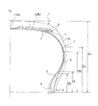
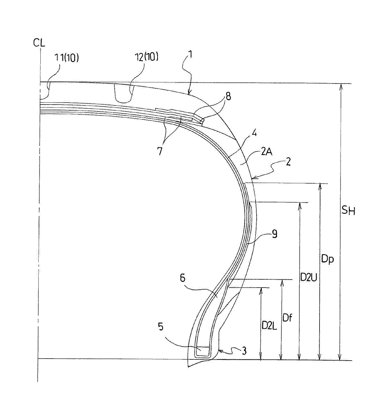
図1に示すように、本実施形態の空気入りタイヤは、タイヤ周方向に延在して環状をなすトレッド部1と、該トレッド部1の両側に配置された一対のサイドウォール部2,2と、これらサイドウォール部2のタイヤ径方向内側に配置された一対のビード部3,3とを備えている。図1はタイヤ中心位置CLからタイヤ幅方向の一方側を描写しているが、他方側もそれに対応する構造を有している。
As shown in FIG. 1, the pneumatic tire according to the present embodiment includes a
一対のビード部3,3間にはカーカス層4が装架されている。このカーカス層4は、タイヤ径方向に延びる複数本のカーカスコードを含み、各ビード部3に配置されたビードコア5の廻りにタイヤ内側から外側へ折り返されている。ビードコア5の外周上には断面三角形状のゴム組成物からなるビードフィラー6が配置されている。
A
一方、トレッド部1におけるカーカス層4の外周側には複数層のベルト層7が埋設されている。これらベルト層7はタイヤ周方向に対して傾斜する複数本のベルトコードを含み、かつ層間でベルトコードが互いに交差するように配置されている。ベルト層7を構成するベルトコードとしては、スチールコードが好ましく使用される。ベルト層7の外周側には、タイヤ周方向に配向する複数本のバンドコードを含む少なくとも1層のベルト補強層8が配置されている。ベルト補強層8は少なくとも1本のバンドコードを引き揃えてゴム被覆してなるストリップ材をタイヤ周方向に連続的に巻回したジョイントレス構造とすることが望ましい。ベルト補強層8を構成するバンドコードとしては、ナイロンやアラミド等の有機繊維コードが好ましく使用される。
On the other hand, a plurality of
図2に示すように、トレッド部1には、タイヤ周方向に延びる複数本の主溝10が形成されている。主溝10は、少なくとも1本のセンター主溝11と、該センター主溝11の外側に位置する一対のショルダー主溝12,12を含んでいる。これら主溝10によりトレッド部1には複数の陸部20が区画されている。陸部20は、一対のショルダー主溝12,12の相互間に位置するセンター陸部21と、各ショルダー主溝12の外側に位置するショルダー陸部22とを含んでいる。各センター陸部21には、一端がショルダー主溝12に開口し、他端がセンター陸部21内で終端する複数本の閉止溝13が形成されている。また、各ショルダー陸部22には、タイヤ幅方向に延在してショルダー主溝12に対して非連通となる複数本のラグ溝14と、タイヤ幅方向に延在してショルダー主溝12に対して連通する複数本のサイプ15とがタイヤ周方向に沿って交互に形成されている。
As shown in FIG. 2, a plurality of
上記空気入りタイヤにおいて、ビードフィラー6のタイヤ径方向の高さDfが空気入りタイヤの断面高さSHに対して0.18≦Df/SH≦0.50の関係を満足している。ビードフィラー6のタイヤ径方向の高さDfはビードヒール位置(リム径の基準位置)からビードフィラー6のタイヤ径方向外側の頂点までの高さである。また、ビードフィラー6を構成するゴム組成物のJIS−A硬度HSfは80≦HSf<100の範囲に設定されている。
In the pneumatic tire, the height Df of the
上記空気入りタイヤにおいて、規格にて定められた最大負荷能力の40%,75%,100%に対応する荷重をそれぞれW40,W75,W100(kN)とし、空気入りタイヤに230kPaの空気圧を充填し、荷重W40,W75,W100を負荷した条件にて測定されるコーナリングパワーをそれぞれCP40,CP75,CP100(kN/°)とし、空気入りタイヤの偏平比をRとし、その外径をD(mm)とし、その断面幅の呼びをA(mm)とする。 In the above pneumatic tire, loads corresponding to 40%, 75%, and 100% of the maximum load capacity defined by the standard are W40, W75, and W100 (kN), respectively, and the pneumatic tire is filled with an air pressure of 230 kPa. , The cornering power measured under the condition that the loads W40, W75, and W100 are applied are respectively CP40, CP75, and CP100 (kN / °), the flatness ratio of the pneumatic tire is R, and the outer diameter is D (mm). And the nominal of the cross-sectional width is A (mm).
ここで、荷重W40,W75,W100及びコーナリングパワーCP40,CP75,CP100は、0.05≦(R×D/2A)2×[(CP100−CP75)/(W100−W75)]/[(CP75−CP40)/(W75−W40)]≦0.50の関係を満足する。 Here, the loads W40, W75, W100 and the cornering powers CP40, CP75, CP100 are 0.05 ≦ (R × D / 2A) 2 × [(CP100−CP75) / (W100−W75)] / [(CP75− CP40) / (W75-W40)] ≦ 0.50.
上述した空気入りタイヤでは、図1に示すように、ビードフィラー6のタイヤ径方向の高さDfを空気入りタイヤの断面高さSHに対して0.18≦Df/SH≦0.50の関係とし、ビードフィラー6を構成するゴム組成物のJIS−A硬度HSfを80≦HSf<100の範囲にすることにより、サイドウォール部2の剛性を高めて旋回時のトレッド部1の滑りを抑制し、耐摩耗性を改善することができる。そして、サイドウォール部2の剛性に基づいて耐摩耗性を改善するので、ベルト層7を含むベルト部の剛性を高める場合とは異なって、高荷重域でのコーナリングパワーの過度の増大を抑制することができる。これにより、操縦安定性のリニアリティを改善することができる。また、サイドウォール部2の剛性を高めることにより、荒れた路面を走行する際に車両に伝わる振動の減衰性を高めることができる。
In the pneumatic tire described above, as shown in FIG. 1, the relation Df of the
ここで、Df/SHの値が0.18より小さいとサイドウォール部2の剛性が不足するため耐摩耗性や振動減衰性の改善効果が不十分になり、逆に0.50よりも大きいと操縦安定性のリニアリティが悪化する。特に、0.22≦Df/SH≦0.40の関係を満足することが望ましい。また、ビードフィラー6を構成するゴム組成物のJIS−A硬度HSfが80未満であるとサイドウォール部2の剛性が不足するため耐摩耗性や振動減衰性の改善効果が不十分になる。特に、JIS−A硬度HSfは86≦HSf<100の範囲にあることが望ましい。なお、ビードフィラー6は一般的にカーボンブラックで補強されたゴム組成物で構成されるが、ナイロンやポリエチレンテレフタレート等の短繊維やセルロースナノファイバーで補強されたゴム組成物で構成されていても良い。
Here, if the value of Df / SH is smaller than 0.18, the rigidity of the
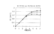
図3はコーナリングパワー(CP)と荷重との関係を示すグラフである。図3において、タイヤCは基準構造を有する空気入りタイヤであり、タイヤAはベルト層7を含むベルト部の剛性を高くした空気入りタイヤであり、タイヤBはベルト部の剛性を高める替わりにサイドウォール部2の剛性を高くした空気入りタイヤである。タイヤA,Cの対比から明らかなように、ベルト部の剛性を高くすると高荷重域でのコーナリングパワーが増大する。これに対して、サイドウォール部2の剛性を高くした場合(タイヤB)、高荷重域でのコーナリングパワーの過度な増大が抑制される。
FIG. 3 is a graph showing the relationship between the cornering power (CP) and the load. In FIG. 3, a tire C is a pneumatic tire having a reference structure, a tire A is a pneumatic tire having a higher rigidity of a belt portion including a
また、上述した空気入りタイヤでは、荷重W40,W75,W100及びコーナリングパワーCP40,CP75,CP100が0.05≦(R×D/2A)2×[(CP100−CP75)/(W100−W75)]/[(CP75−CP40)/(W75−W40)]≦0.50の関係を満足することにより、高荷重域のコーナリングパワーの過度の増大を抑制することができる。これにより、荷重の増大に伴って適度なコーナリングパワーが発揮されるので、操縦安定性のリニアリティを改善することができる。特に、上記関係式は(R×D/2A)2の値により補正されているので、偏平比が低く、断面幅の呼びに対する外径の比が小さいタイヤほど高荷重側のコーナリングパワーの寄与を低下させる。そのため、タイヤサイズに応じて適度なコーナリングパワーを発揮することができる。 In the pneumatic tire described above, the loads W40, W75, W100 and the cornering powers CP40, CP75, CP100 are 0.05 ≦ (R × D / 2A) 2 × [(CP100−CP75) / (W100−W75)]. By satisfying the relationship of /[(CP75-CP40)/(W75-W40)]≦0.50, it is possible to suppress an excessive increase in cornering power in a high load range. As a result, an appropriate cornering power is exhibited as the load increases, so that the linearity of the steering stability can be improved. In particular, since the above relational expression is corrected by the value of (R × D / 2A) 2 , the tire having a lower aspect ratio and a smaller ratio of the outer diameter to the nominal sectional width contributes to the contribution of the cornering power on the higher load side. Lower. Therefore, an appropriate cornering power can be exhibited according to the tire size.
ここで、(R×D/2A)2×[(CP100−CP75)/(W100−W75)]/[(CP75−CP40)/(W75−W40)]が0.05よりも小さいと低荷重域でのコーナリングパワーが過剰となり、逆に0.50よりも大きいと高荷重域でのコーナリングパワーが過剰となり、いずれの場合も、操縦安定性のリニアリティが損なわれることになる。特に、0.10≦(R×D/2A)2×[(CP100−CP75)/(W100−W75)]/[(CP75−CP40)/(W75−W40)]≦0.40の関係を満足することが望ましい。 Here, when (R × D / 2A) 2 × [(CP100-CP75) / (W100-W75)] / [(CP75-CP40) / (W75-W40)] is smaller than 0.05, the low load range is obtained. If the cornering power is too large, on the other hand, if it is larger than 0.50, the cornering power in the high load range becomes excessive, and in any case, the linearity of the steering stability is impaired. In particular, the relationship 0.10 ≦ (R × D / 2A) 2 × [(CP100-CP75) / (W100-W75)] / [(CP75-CP40) / (W75-W40)] ≦ 0.40 is satisfied. It is desirable to do.
図4は図1の空気入りタイヤを構成するベルト層を示すものである。上記空気入りタイヤにおいて、ベルト層7のタイヤ周方向に対するコード角度θは18°≦θ≦34°の範囲に設定されていると良い。ベルト層7のコード角度θはタイヤ中心位置CLにおけるベルトコードのタイヤ周方向に対する傾斜角度である。ベルト層7のコード角度θを小さくするとベルト層7の剛性が大きくなる傾向があるが、ベルト層7の剛性が過度に大きくならない範囲において、サイドウォール部2の剛性を増加させることで、操縦安定性のリニアリティを効果的に改善することができる。
FIG. 4 shows a belt layer constituting the pneumatic tire of FIG. In the pneumatic tire, the cord angle θ of the
ここで、ベルト層7のタイヤ周方向に対するコード角度θが18°よりも小さいベルト層7の剛性が大き過ぎるため操縦安定性のリニアリティが悪化する要因となり、逆に34°よりも大きいとベルト層7の剛性が低過ぎるためドレッド部1とサイドウォール部2との剛性バランスが悪化する。コード角度θにはタイヤサイズにより好適な範囲がある。偏平比Rが0.65超である場合、18°≦θ≦30°が好ましく、特に21°≦θ≦29°が好ましい。偏平比Rが0.65以下である場合、21°≦θ≦34°が好ましく、特に22°≦θ≦32°が好ましい。
Here, when the cord angle θ of the
上記空気入りタイヤにおいて、ビードフィラー6を構成するゴム組成物の20℃における貯蔵弾性率E′は70MPa≦E′≦130MPaの範囲にあると良い。ビードフィラー6を構成するゴム組成物の貯蔵弾性率E′を上記範囲に設定することにより、振動減衰性を高めることができる。この貯蔵弾性率E′が70MPaよりも小さいと振動減衰性を高める効果が低下し、逆に130MPaよりも大きいと操縦安定性のリニアリティの改善効果が低下する。特に、貯蔵弾性率E′は77MPa≦E′≦120MPaの範囲にあることが望ましい。
In the pneumatic tire, the storage modulus E ′ at 20 ° C. of the rubber composition constituting the
上記空気入りタイヤにおいて、図1に示すように、ビードフィラー6の高さDfの中間位置(Df/2)におけるビードフィラー6のタイヤ幅方向の厚さWhとビードフィラーの高さDfの中間位置におけるサイドウォール部2のタイヤ幅方向の総厚さWtは0.35≦Wh/Wt≦0.80の関係を満足すると良い。剛性が高いビードフィラー6がサイドウォール部2に占める割合を高くすることにより、サイドウォール部2の剛性を効果的に増大させることができ、その結果、耐摩耗性や振動減衰性を改善することができる。ここで、Wh/Wtの値が0.35よりも小さいとサイドウォール部2の剛性が不十分になり、逆に0.80よりも大きいとサイドウォール部2の剛性が過度に高くなるため操縦安定性のリニアリティが悪化する。
In the pneumatic tire, as shown in FIG. 1, the thickness Wh of the
上記空気入りタイヤにおいて、図1に示すように、カーカス層4の巻き上げ高さDpはDf<Dp<SHかつ5mm≦Dp−Dfの関係を満足すると良い。カーカス層4の巻き上げ高さDpをビードフィラー6の高さDfよりも大きくすることにより、サイドウォール部2の剛性を効果的に増大させることができ、その結果、耐摩耗性や振動減衰性を改善することができる。また、Dp−Dfの値を十分に確保することで、応力集中を回避してタイヤ故障を抑制することができる。ここで、Dp−Dfの値が5mmよりも小さいとビードフィラー6の頂点とカーカス層4の巻き上げ端とが近接するため応力集中に起因するタイヤ故障を生じ易くなる。
In the pneumatic tire, as shown in FIG. 1, it is preferable that the winding height Dp of the
図5は本発明の他の実施形態からなる空気入りタイヤを示すものである。図5において、図1と同一物には同一符号を付してその部分の詳細な説明は省略する。図5に示すように、ビードフィラー6のタイヤ径方向外側の位置には第2フィラー9が配設されている。第2フィラー9はシート状をなし、カーカス層4のタイヤ幅方向外側で該カーカス層4に沿って配置されている。第2フィラー9を構成するゴム組成物のJIS−A硬度HS2は70≦HS2<90かつHS2≦HSfの関係を満足すると良い。このような第2フィラー9を追加することにより、サイドウォール部2の剛性を効果的に増大させることができ、その結果、耐摩耗性や振動減衰性を改善することができる。また、第2フィラー9のゴム組成物のJIS−A硬度HS2をビードフィラー6のゴム組成物のJIS−A硬度HSfよりも小さくすることで、サイドウォール部2の剛性を効果的に増大させる一方で、高荷重域のコーナリングパワーの過度の増大を抑制することができる。
FIG. 5 shows a pneumatic tire according to another embodiment of the present invention. 5, the same components as those in FIG. 1 are denoted by the same reference numerals, and the detailed description of those portions will be omitted. As shown in FIG. 5, a
ここで、第2フィラー9を構成するゴム組成物のJIS−A硬度HS2が70よりも小さいとサイドウォール部2の剛性を高くする効果が低下し、逆に90以上であったりビードフィラー6のJIS−A硬度HSfよりも高かったりすると高荷重域のコーナリングパワーが過度に増大する。
Here, if the JIS-A hardness HS2 of the rubber composition constituting the
上記空気入りタイヤにおいて、図5に示すように、第2フィラー9の下端のタイヤ径方向の高さD2L及び第2フィラー9の上端のタイヤ径方向の高さD2UはD2L<Df<D2U<0.80×SHかつ0.1×Df≦Df−D2L≦0.5×Dfの関係を満足すると良い。第2フィラー9をビードフィラー6に対してタイヤ径方向に重複させることにより、サイドウォール部2の剛性を効果的に増大させることができ、その結果、耐摩耗性や振動減衰性を改善することができる。また、Df−D2Lの値を十分に確保することで、応力集中を回避してタイヤ故障を抑制することができる。更に、第2フィラー9の上端のタイヤ径方向の高さD2Uを空気入りタイヤの断面高さSHに対して十分に小さくすることにより、コーナリングパワーのバランスを最適化することができる。
In the pneumatic tire, as shown in FIG. 5, the height D2L of the lower end of the
ここで、第2フィラー9の下端のタイヤ径方向の高さD2Lがビードフィラー6の高さDfよりも大きいとビードフィラー6と第2フィラー9とが連続的に配置されないためサイドウォール部2の剛性を効果的に増大させることができなくなる。また、Df−D2Lの値が0.1×Dfよりも小さいとビードフィラー6の頂点と第2フィラー9の下端とが近接するため応力集中に起因するタイヤ故障を生じ易くなり、逆に0.5×Dfよりも大きいとサイドウォール部2の剛性が過度に高くなる。更に、第2フィラー9の上端のタイヤ径方向の高さD2Uが0.80×SH以上に大きいと操縦安定性のリニアリティが悪化する。
Here, if the height D2L of the lower end of the
上述した空気入りタイヤにおいて、サイドウォール部2におけるカーカス層4の外側に配置されるサイドゴム層2Aを構成するゴム組成物のJIS−A硬度HSsは55≦HSs<80≦HSfの関係を満足すると良い。サイドゴム層2Aを構成するゴム組成物のJIS−A硬度HSsを比較的高くすることにより、サイドウォール部2の剛性を効果的に増大させることができ、その結果、耐摩耗性や振動減衰性を改善することができる。また、サイドゴム層2Aのゴム組成物のJIS−A硬度HSsをビードフィラー6のゴム組成物のJIS−A硬度HSfよりも低くすることで、高荷重域のコーナリングパワーの過度の増大を抑制することができる。
In the pneumatic tire described above, the JIS-A hardness HSs of the rubber composition constituting the
ここで、サイドゴム層2Aを構成するゴム組成物のJIS−A硬度HSsが55よりも小さいとサイドウォール部2の剛性を効果的に増大させることができなくなり、逆に80以上であったりビードフィラー6のJIS−A硬度HSfよりも高かったりすると高荷重域のコーナリングパワーが過度に増大する。
Here, if the JIS-A hardness HSs of the rubber composition constituting the
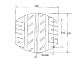
図6〜図8はそれぞれ図1又は図2の空気入りタイヤの接地形状(40%荷重、75%荷重、100%荷重)を示すものである。上記空気入りタイヤにおいて、該空気入りタイヤに230kPaの空気圧を充填し、規格にて定められた最大負荷能力のそれぞれ40%,75%,100%の荷重を負荷した条件にて接地した際のタイヤ周方向の最大接地長をそれぞれLA1,LB1,LC1(mm)とし、タイヤ幅方向の最大接地幅をそれぞれWA1,WB1,WC1(mm)とし、タイヤ中心位置からタイヤ幅方向外側に向かって最大接地幅WA1,WB1,WC1の40%の位置におけるタイヤ周方向の外部接地長をそれぞれLA2,LB2,LC2(mm)とする。 6 to 8 show the ground contact shapes (40% load, 75% load, 100% load) of the pneumatic tire of FIG. 1 or FIG. 2, respectively. In the above pneumatic tire, the tire when the pneumatic tire is filled with an air pressure of 230 kPa and grounded under the conditions of applying a load of 40%, 75%, and 100% of the maximum load capacity specified by the standard, respectively. The maximum ground contact lengths in the circumferential direction are LA1, LB1, and LC1 (mm), and the maximum ground contact widths in the tire width direction are WA1, WB1, and WC1 (mm), respectively. External ground contact lengths in the tire circumferential direction at positions of 40% of the widths WA1, WB1, and WC1 are LA2, LB2, and LC2 (mm), respectively.
つまり、図6に示すように、上記空気入りタイヤに230kPaの空気圧を充填し、規格にて定められた最大負荷能力の40%の荷重を負荷した条件にて接地した際のタイヤ周方向の最大接地長をLA1とし、タイヤ幅方向の最大接地幅をWA1とし、タイヤ中心位置CLからタイヤ幅方向外側に向かって最大接地幅WA1の40%の位置におけるタイヤ周方向の外部接地長をLA2とする。外部接地長LA2はタイヤ中心位置CLの両側における測定値の平均値である。 That is, as shown in FIG. 6, when the pneumatic tire is filled with pneumatic pressure of 230 kPa and is grounded under the condition that a load of 40% of the maximum load capacity specified in the standard is applied, the maximum in the tire circumferential direction is obtained. The contact length is LA1, the maximum contact width in the tire width direction is WA1, and the external contact length in the tire circumferential direction at a position 40% of the maximum contact width WA1 from the tire center position CL to the outside in the tire width direction is LA2. . The external contact length LA2 is an average value of measured values on both sides of the tire center position CL.
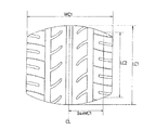
また、図7に示すように、上記空気入りタイヤに230kPaの空気圧を充填し、規格にて定められた最大負荷能力の75%の荷重を負荷した条件にて接地した際のタイヤ周方向の最大接地長をLB1とし、タイヤ幅方向の最大接地幅をWB1とし、タイヤ中心位置CLからタイヤ幅方向外側に向かって最大接地幅WB1の40%の位置におけるタイヤ周方向の外部接地長をLB2とする。外部接地長LB2はタイヤ中心位置CLの両側における測定値の平均値である。 As shown in FIG. 7, when the pneumatic tire is filled with an air pressure of 230 kPa and is grounded under the condition that a load of 75% of the maximum load capacity specified in the standard is applied, the maximum in the tire circumferential direction is obtained. The contact length is LB1, the maximum contact width in the tire width direction is WB1, and the external contact length in the tire circumferential direction at a position 40% of the maximum contact width WB1 from the tire center position CL to the outside in the tire width direction is LB2. . The external contact length LB2 is an average value of the measured values on both sides of the tire center position CL.
更に、図8に示すように、上記空気入りタイヤに230kPaの空気圧を充填し、規格にて定められた最大負荷能力の100%の荷重を負荷した条件にて接地した際のタイヤ周方向の最大接地長をLC1とし、タイヤ幅方向の最大接地幅をWC1とし、タイヤ中心位置CLからタイヤ幅方向外側に向かって最大接地幅WC1の40%の位置におけるタイヤ周方向の外部接地長をLC2とする。外部接地長LC2はタイヤ中心位置CLの両側における測定値の平均値である。 Further, as shown in FIG. 8, when the pneumatic tire is filled with an air pressure of 230 kPa and the tire is grounded under the condition that a load of 100% of the maximum load capacity specified in the standard is applied, the maximum in the tire circumferential direction is obtained. The contact length is LC1, the maximum contact width in the tire width direction is WC1, and the external contact length in the tire circumferential direction at a position 40% of the maximum contact width WC1 from the tire center position CL to the outside in the tire width direction is LC2. . The external contact length LC2 is an average value of measured values on both sides of the tire center position CL.
ここで、最大接地長LA1,LB1,LC1及び外部接地長LA2,LB2,LC2は以下の関係を満足すると良い。
1.02≦(LB2/LB1)/(LA2/LA1)≦1.25
1.00≦(LC2/LC1)/(LB2/LB1)≦1.20
0.75≦LB2/LB1≦1.00
Here, it is preferable that the maximum ground lengths LA1, LB1, and LC1 and the external ground lengths LA2, LB2, and LC2 satisfy the following relationship.
1.02 ≦ (LB2 / LB1) / (LA2 / LA1) ≦ 1.25
1.00 ≦ (LC2 / LC1) / (LB2 / LB1) ≦ 1.20
0.75 ≦ LB2 / LB1 ≦ 1.00
このように接地形状の荷重依存性をコントロールすることにより、操縦安定性のリニアリティを更に改善することができる。つまり、LA2/LA1は40%荷重時の矩形率を意味し、LB2/LB1は75%荷重時の矩形率を意味し、LC2/LC1は100%荷重時の矩形率を意味するものであるが、低荷重域の接地形状をコントロールするための指標として(LB2/LB1)/(LA2/LA1)の値を規定し、高荷重域の接地形状をコントロールするための指標として(LC2/LC1)/(LB2/LB1)の値を規定することにより、操縦安定性のリニアリティを更に改善することができる。 By controlling the load dependency of the ground contact shape in this way, the linearity of steering stability can be further improved. That is, LA2 / LA1 means the rectangular ratio under a 40% load, LB2 / LB1 means the rectangular ratio under a 75% load, and LC2 / LC1 means the rectangular ratio under a 100% load. The value of (LB2 / LB1) / (LA2 / LA1) is defined as an index for controlling the contact shape in the low load region, and (LC2 / LC1) / is used as an index for controlling the contact shape in the high load region. By defining the value of (LB2 / LB1), the linearity of the steering stability can be further improved.
ここで、(LB2/LB1)/(LA2/LA1)又は(LC2/LC1)/(LB2/LB1)が上記範囲から外れると操縦安定性のリニアリティの改善効果が低下する。特に、1.03≦(LB2/LB1)/(LA2/LA1)≦1.15、1.02≦(LC2/LC1)/(LB2/LB1)≦1.10の関係を満足することが望ましい。 Here, if (LB2 / LB1) / (LA2 / LA1) or (LC2 / LC1) / (LB2 / LB1) is out of the above range, the effect of improving the linearity of the steering stability decreases. In particular, it is desirable to satisfy the following relations: 1.03 ≦ (LB2 / LB1) / (LA2 / LA1) ≦ 1.15, 1.02 ≦ (LC2 / LC1) / (LB2 / LB1) ≦ 1.10.
また、摩耗寿命を向上するために、一般常用荷重とみなされる75%の荷重条件において、LB2/LB1を上記範囲に設定することが望ましい。LB2/LB1が0.75よりも小さいと摩耗寿命が短くなり、逆に1.00よりも大きいと操縦安定性のリニアリティのチューニングが難しくなる。特に、0.80≦LB2/LB1≦0.95の関係を満足することが望ましい。 In order to improve the wear life, it is desirable to set LB2 / LB1 in the above range under a load condition of 75% which is regarded as a general normal load. If LB2 / LB1 is smaller than 0.75, the wear life is shortened, and if it is larger than 1.00, tuning of steering stability linearity becomes difficult. In particular, it is desirable to satisfy the relationship of 0.80 ≦ LB2 / LB1 ≦ 0.95.
上述した空気入りタイヤは偏平比0.65以下の乗用車用タイヤとして好適である。操縦安定性のリニアリティや乗心地が厳しく要求される乗用車用タイヤにおいて、耐偏摩耗性と操縦安定性とを両立し、更には乗心地(振動減衰性)を改善することが可能になる。 The pneumatic tire described above is suitable as a tire for passenger cars having an aspect ratio of 0.65 or less. In a passenger car tire that requires strict linearity and riding comfort of steering stability, it is possible to achieve both uneven wear resistance and steering stability, and further improve riding comfort (vibration damping property).
タイヤサイズ205/55R16 91Vで、一対のビード部間に装架されたカーカス層と、トレッド部におけるカーカス層のタイヤ径方向外側に配置された2層のベルト層と、ビード部の各々に配置されたビードコアと、該ビードコアのタイヤ径方向外側に配置されたビードフィラーとを備えた空気入りタイヤにおいて、ベルト層のタイヤ周方向に対するコード角度θ、空気入りタイヤの断面高さSH、ビードフィラーのタイヤ径方向の高さDf、Df/SH、ビードフィラーを構成するゴム組成物のJIS−A硬度HSf、ビードフィラーを構成するゴム組成物の20℃における貯蔵弾性率E′、ビードフィラーの高さDfの中間位置におけるビードフィラーのタイヤ幅方向の厚さWh、ビードフィラーの高さDfの中間位置におけるサイドウォール部のタイヤ幅方向の総厚さWt、Wh/Wt、カーカス層の巻き上げ高さDp、Dp−Df、第2フィラーを構成するゴム組成物のJIS−A硬度HS2、第2フィラーの下端のタイヤ径方向の高さD2L、第2フィラーの上端のタイヤ径方向の高さD2U、Df−D2L、サイドゴム層を構成するゴム組成物のJIS−A硬度HSs、低荷重域CP変動係数X=[(CP75−CP40)/(W75−W40)]、高荷重域CP変動係数Y=[(CP100−CP75)/(W100−W75)]、(R×D/2A)2×(Y/X)、(LB2/LB1)/(LA2/LA1)、(LC2/LC1)/(LB2/LB1)、LB2/LB1(矩形率)を表1及び表2のように設定した従来例、比較例1〜2及び実施例1〜8のタイヤを製作した。 A tire having a tire size of 205 / 55R16 91V, a carcass layer mounted between a pair of bead portions, two belt layers disposed radially outside the carcass layer in the tread portion, and a bead portion. Tire having a bead core and a bead filler disposed radially outward of the bead core, the cord angle θ of the belt layer with respect to the tire circumferential direction, the cross-section height SH of the pneumatic tire, the tire of the bead filler Radial height Df, Df / SH, JIS-A hardness HSf of the rubber composition constituting the bead filler, storage elastic modulus E 'at 20 ° C. of the rubber composition constituting the bead filler, height Df of the bead filler At the intermediate position between the thickness Wh of the bead filler in the tire width direction at the intermediate position of the tire and the height Df of the bead filler. The total thickness Wt, Wh / Wt of the wall portion in the tire width direction, the winding height Dp, Dp-Df of the carcass layer, the JIS-A hardness HS2 of the rubber composition constituting the second filler, and the lower end of the second filler. The height D2L in the tire radial direction, the height D2U in the tire radial direction at the upper end of the second filler, Df-D2L, the JIS-A hardness HSs of the rubber composition constituting the side rubber layer, and the low load range CP variation coefficient X = [ (CP75-CP40) / (W75-W40)], high load range CP variation coefficient Y = [(CP100-CP75) / (W100-W75)], (R × D / 2A) 2 × (Y / X), Conventional examples in which (LB2 / LB1) / (LA2 / LA1), (LC2 / LC1) / (LB2 / LB1), and LB2 / LB1 (rectangular ratio) are set as shown in Tables 1 and 2, and Comparative Examples 1 and 2. And ties of Examples 1 to 8 It was manufactured.
これら試験タイヤについて、下記試験方法により、耐摩耗性(ショルダー領域、センター領域)、操縦安定性のリニアリティ、乗心地[振動減衰性]を評価し、その結果を表1及び表2に併せて示した。 These test tires were evaluated for wear resistance (shoulder area, center area), steering stability linearity, and riding comfort [vibration damping property] by the following test methods, and the results are shown in Tables 1 and 2. Was.
耐摩耗性(ショルダー領域、センター領域):
各試験タイヤをリムサイズ16×6.5Jのホイールに組み付けて摩擦エネルギー測定試験機に装着し、空気圧230kPa、負荷荷重4.5kNの条件下にて、トレッド部のショルダー領域及びセンター領域での平均摩擦エネルギーを測定した。測定値は、各領域で10mm間隔となるタイヤ幅方向2箇所×タイヤ周方向2箇所の計4点における摩擦エネルギーを測定し、これらを平均したものである。評価結果は、測定値の逆数を用い、従来例を100とする指数にて示した。指数値が大きいほど耐摩耗性が優れていることを意味する。
Abrasion resistance (shoulder area, center area):
Each test tire was mounted on a wheel having a rim size of 16 × 6.5 J and mounted on a friction energy measurement tester. The average friction in the shoulder region and the center region of the tread portion under the conditions of an air pressure of 230 kPa and a load of 4.5 kN. Energy was measured. The measured values are obtained by measuring the friction energies at a total of four points at two locations in the tire width direction × two locations in the tire circumferential direction at intervals of 10 mm in each region, and averaging these. The evaluation results were represented by an index using the reciprocal of the measured value and the conventional example as 100. The larger the index value, the better the wear resistance.
操縦安定性のリニアリティ:
各試験タイヤをリムサイズ16×6.5Jのホイールに組み付けて排気量2リットルの前輪駆動車に装着し、当該車両の指定空気圧を充填し、舗装路からなるテストコースにてパネラーによる走行試験を実施し、操縦安定性のリニアリティについて官能評価を行った。評価結果は、比較例2を100とする指数にて示した。指数値が大きいほど操縦安定性のリニアリティが良好であることを意味する。
Linearity of handling stability:
Each test tire is mounted on a rim size 16 x 6.5 J wheel, mounted on a front-wheel drive vehicle with a displacement of 2 liters, filled with the specified air pressure of the vehicle, and run by a panelist on a test course consisting of paved roads Then, the sensory evaluation was performed on the linearity of the steering stability. The evaluation results were indicated by an index with Comparative Example 2 being 100. The larger the index value, the better the linearity of the steering stability.
乗心地[振動減衰性]:
各試験タイヤをリムサイズ16×6.5Jのホイールに組み付けて排気量2リットルの前輪駆動車に装着し、当該車両の指定空気圧を充填し、舗装路からなるテストコースにてパネラーによる走行試験を実施し、乗心地[振動減衰性]について官能評価を行った。評価結果は、従来を100とする指数にて示した。指数値が大きいほど乗心地[振動減衰性]が良好であることを意味する。
Ride comfort [vibration damping]:
Each test tire is mounted on a rim size 16 x 6.5 J wheel, mounted on a front-wheel drive vehicle with a displacement of 2 liters, filled with the specified air pressure of the vehicle, and run by a panelist on a test course consisting of paved roads Then, the sensory evaluation was performed on the riding comfort [vibration damping property]. The evaluation results are shown by an index with the conventional value being 100. The larger the index value, the better the ride comfort [vibration damping property].
この表1及び表2から判るように、実施例1〜8のタイヤは、従来例との対比において、耐摩耗性が優れていると共に、操縦安定性のリニアリティが良好であり、しかも、走行時の振動減衰性が良好であって乗心地が優れていた。これに対して、比較例1のタイヤは、ビードフィラーが小さいため耐摩耗性や乗心地[振動減衰性]の改善効果が得られなかった。また、比較例2のタイヤは、従来例と同様に軟らかいビードフィラーを備える一方で、ベルト層のコード角度θを小さくしてベルト部の剛性を高めているため、操縦安定性のリニアリティが必ずしも良好ではなく、また、乗心地[振動減衰性]の改善効果が得られなかった。 As can be seen from Tables 1 and 2, the tires of Examples 1 to 8 have excellent abrasion resistance, good linearity of steering stability, and good running performance in comparison with the conventional example. Had good vibration damping properties and excellent ride comfort. On the other hand, in the tire of Comparative Example 1, the effect of improving wear resistance and ride comfort [vibration damping property] was not obtained because the bead filler was small. In addition, the tire of Comparative Example 2 has a soft bead filler as in the conventional example, but has a small cord angle θ of the belt layer to increase the rigidity of the belt portion. However, the improvement effect of the riding comfort [vibration damping property] was not obtained.
1 トレッド部
2 サイドウォール部
3 ビード部
4 カーカス層
5 ビードコア
6 ビードフィラー
7 ベルト層
8 ベルト補強層
9 第2フィラー
10 主溝
11 センター主溝
12 ショルダー主溝
DESCRIPTION OF
Claims (10)
前記ビードフィラーのタイヤ径方向の高さDfが前記空気入りタイヤの断面高さSHに対して0.18≦Df/SH≦0.50の関係を満足し、前記ビードフィラーを構成するゴム組成物のJIS−A硬度HSfが80≦HSf<100の範囲にあり、
規格にて定められた最大負荷能力の40%,75%,100%に対応する荷重をそれぞれW40,W75,W100(kN)とし、前記空気入りタイヤに230kPaの空気圧を充填し、前記荷重W40,W75,W100を負荷した条件にて測定されるコーナリングパワーをそれぞれCP40,CP75,CP100(kN/°)とし、前記空気入りタイヤの偏平比をRとし、その外径をD(mm)とし、その断面幅の呼びをA(mm)としたとき、前記荷重W40,W75,W100及び前記コーナリングパワーCP40,CP75,CP100が0.05≦(R×D/2A)2×[(CP100−CP75)/(W100−W75)]/[(CP75−CP40)/(W75−W40)]≦0.50の関係を満足することを特徴とする空気入りタイヤ。 A ring-shaped tread portion extending in the tire circumferential direction, a pair of sidewall portions disposed on both sides of the tread portion, and a pair of bead portions disposed inside the tire radial direction of these sidewall portions, A carcass layer mounted between the pair of bead portions, a plurality of belt layers disposed radially outward of the carcass layer in the tread portion, and a bead core disposed on each of the bead portions; In a pneumatic tire having a bead filler disposed radially outward of the bead core,
A rubber composition constituting the bead filler, wherein a height Df of the bead filler in the tire radial direction satisfies a relationship of 0.18 ≦ Df / SH ≦ 0.50 with respect to a cross-sectional height SH of the pneumatic tire. JIS-A hardness HSf is in the range of 80 ≦ HSf <100,
Loads corresponding to 40%, 75%, and 100% of the maximum load capacity defined by the standard are W40, W75, and W100 (kN), respectively. The pneumatic tire is filled with an air pressure of 230 kPa, and The cornering power measured under the condition of loading W75 and W100 is CP40, CP75 and CP100 (kN / °), the flatness ratio of the pneumatic tire is R, and the outer diameter is D (mm). When the nominal of the sectional width is A (mm), the load W40, W75, W100 and the cornering power CP40, CP75, CP100 are 0.05 ≦ (R × D / 2A) 2 × [(CP100−CP75) / (W100-W75)] / [(CP75-CP40) / (W75-W40)] ≦ 0.50 Tire enters.
Priority Applications (1)
| Application Number | Priority Date | Filing Date | Title |
|---|---|---|---|
| JP2018130351A JP7187852B2 (en) | 2018-07-10 | 2018-07-10 | pneumatic tire |
Applications Claiming Priority (1)
| Application Number | Priority Date | Filing Date | Title |
|---|---|---|---|
| JP2018130351A JP7187852B2 (en) | 2018-07-10 | 2018-07-10 | pneumatic tire |
Publications (2)
| Publication Number | Publication Date |
|---|---|
| JP2020006842A true JP2020006842A (en) | 2020-01-16 |
| JP7187852B2 JP7187852B2 (en) | 2022-12-13 |
Family
ID=69150301
Family Applications (1)
| Application Number | Title | Priority Date | Filing Date |
|---|---|---|---|
| JP2018130351A Active JP7187852B2 (en) | 2018-07-10 | 2018-07-10 | pneumatic tire |
Country Status (1)
| Country | Link |
|---|---|
| JP (1) | JP7187852B2 (en) |
Cited By (2)
| Publication number | Priority date | Publication date | Assignee | Title |
|---|---|---|---|---|
| CN111993846A (en) * | 2020-08-24 | 2020-11-27 | 安徽佳通乘用子午线轮胎有限公司 | Small-size all-steel tire with high bearing performance |
| JP2023014839A (en) * | 2021-07-19 | 2023-01-31 | 住友ゴム工業株式会社 | tire |
Citations (1)
| Publication number | Priority date | Publication date | Assignee | Title |
|---|---|---|---|---|
| JPS6092103A (en) * | 1983-10-25 | 1985-05-23 | Yokohama Rubber Co Ltd:The | Radial tire for passenger car |
-
2018
- 2018-07-10 JP JP2018130351A patent/JP7187852B2/en active Active
Patent Citations (1)
| Publication number | Priority date | Publication date | Assignee | Title |
|---|---|---|---|---|
| JPS6092103A (en) * | 1983-10-25 | 1985-05-23 | Yokohama Rubber Co Ltd:The | Radial tire for passenger car |
Cited By (4)
| Publication number | Priority date | Publication date | Assignee | Title |
|---|---|---|---|---|
| CN111993846A (en) * | 2020-08-24 | 2020-11-27 | 安徽佳通乘用子午线轮胎有限公司 | Small-size all-steel tire with high bearing performance |
| CN111993846B (en) * | 2020-08-24 | 2022-05-31 | 安徽佳通乘用子午线轮胎有限公司 | Small-size all-steel tire with high bearing performance |
| JP2023014839A (en) * | 2021-07-19 | 2023-01-31 | 住友ゴム工業株式会社 | tire |
| JP7707710B2 (en) | 2021-07-19 | 2025-07-15 | 住友ゴム工業株式会社 | tire |
Also Published As
| Publication number | Publication date |
|---|---|
| JP7187852B2 (en) | 2022-12-13 |
Similar Documents
| Publication | Publication Date | Title |
|---|---|---|
| JP6537496B2 (en) | Pneumatic tire | |
| JP6729809B2 (en) | Pneumatic tire | |
| JP6729808B2 (en) | Pneumatic tire | |
| WO2013065318A1 (en) | Pneumatic radial tire for passenger car | |
| WO2015063977A1 (en) | Tire | |
| US11590802B2 (en) | Pneumatic tire | |
| JP2020108989A (en) | Pneumatic tire | |
| US20160243897A1 (en) | Pneumatic tire | |
| JP5251178B2 (en) | Pneumatic tire | |
| JP7187852B2 (en) | pneumatic tire | |
| JP2006273240A (en) | Pneumatic tire for motorcycle | |
| JP2021091365A (en) | Pneumatic tire | |
| JP6828442B2 (en) | Pneumatic tires | |
| JP2010221820A (en) | Pneumatic tire | |
| JP5298797B2 (en) | Pneumatic tire | |
| JP7255327B2 (en) | pneumatic tire | |
| JP6294792B2 (en) | Pneumatic tire | |
| JP5251179B2 (en) | Pneumatic tire | |
| JP4915069B2 (en) | Pneumatic tire | |
| JP7287178B2 (en) | pneumatic tire | |
| JP7234756B2 (en) | pneumatic tire | |
| JP7360020B2 (en) | pneumatic tires | |
| JP7031402B2 (en) | Pneumatic tires | |
| JP6294791B2 (en) | Pneumatic tire | |
| JP2017121848A (en) | Pneumatic tire |
Legal Events
| Date | Code | Title | Description |
|---|---|---|---|
| A621 | Written request for application examination |
Free format text: JAPANESE INTERMEDIATE CODE: A621 Effective date: 20210705 |
|
| A977 | Report on retrieval |
Free format text: JAPANESE INTERMEDIATE CODE: A971007 Effective date: 20220704 |
|
| A131 | Notification of reasons for refusal |
Free format text: JAPANESE INTERMEDIATE CODE: A131 Effective date: 20220712 |
|
| A521 | Request for written amendment filed |
Free format text: JAPANESE INTERMEDIATE CODE: A523 Effective date: 20220829 |
|
| TRDD | Decision of grant or rejection written | ||
| A01 | Written decision to grant a patent or to grant a registration (utility model) |
Free format text: JAPANESE INTERMEDIATE CODE: A01 Effective date: 20221101 |
|
| A61 | First payment of annual fees (during grant procedure) |
Free format text: JAPANESE INTERMEDIATE CODE: A61 Effective date: 20221114 |
|
| R150 | Certificate of patent or registration of utility model |
Ref document number: 7187852 Country of ref document: JP Free format text: JAPANESE INTERMEDIATE CODE: R150 |
|
| S531 | Written request for registration of change of domicile |
Free format text: JAPANESE INTERMEDIATE CODE: R313531 |
|
| R350 | Written notification of registration of transfer |
Free format text: JAPANESE INTERMEDIATE CODE: R350 |
|
| R250 | Receipt of annual fees |
Free format text: JAPANESE INTERMEDIATE CODE: R250 |