JP2020006865A - Humidifying air supply device - Google Patents

Humidifying air supply device Download PDF

Info

Publication number
JP2020006865A
JP2020006865A JP2018131021A JP2018131021A JP2020006865A JP 2020006865 A JP2020006865 A JP 2020006865A JP 2018131021 A JP2018131021 A JP 2018131021A JP 2018131021 A JP2018131021 A JP 2018131021A JP 2020006865 A JP2020006865 A JP 2020006865A
Authority
JP
Japan
Prior art keywords
air
humidification
heating device
adsorbent
heat
Prior art date
Legal status (The legal status is an assumption and is not a legal conclusion. Google has not performed a legal analysis and makes no representation as to the accuracy of the status listed.)
Pending
Application number
JP2018131021A
Other languages
Japanese (ja)
Inventor
好児 藤井
Kouji Fujii
好児 藤井
Current Assignee (The listed assignees may be inaccurate. Google has not performed a legal analysis and makes no representation or warranty as to the accuracy of the list.)
Denso Corp
Original Assignee
Denso Corp
Priority date (The priority date is an assumption and is not a legal conclusion. Google has not performed a legal analysis and makes no representation as to the accuracy of the date listed.)
Filing date
Publication date
Application filed by Denso Corp filed Critical Denso Corp
Priority to JP2018131021A priority Critical patent/JP2020006865A/en
Publication of JP2020006865A publication Critical patent/JP2020006865A/en
Pending legal-status Critical Current

Links

Images

Landscapes

  • Air-Conditioning For Vehicles (AREA)

Abstract

【課題】車両において温風を供給できる熱量を得にくい状態であっても加湿空気を供給可能な加湿空気供給装置を提供する。【解決手段】加湿空気供給装置は、車室内に送風する空気を加熱する加熱装置を有する空調装置と、加熱装置によって加熱された空気を加熱可能な補助加熱装置と、加湿ユニットと、補助加熱装置の運転と加湿ユニットの運転とを制御する制御装置とを備える。制御装置は、ステップS100で加熱装置を通過後の空気温度について加湿可能温度条件が成立するか否かを判定する。加湿可能温度条件が成立する場合にはステップS120で補助加熱装置を制御して加熱装置を通過後の空気を加熱し、ステップS130で加湿ユニットを制御して補助加熱装置によって加熱された空気を吸着材に供給する。【選択図】図7PROBLEM TO BE SOLVED: To provide a humidified air supply device capable of supplying humidified air even in a state where it is difficult to obtain a heat quantity capable of supplying warm air in a vehicle. A humidified air supply device includes an air conditioner having a heating device that heats air blown into a passenger compartment, an auxiliary heating device that can heat air heated by the heating device, a humidifying unit, and an auxiliary heating device. And a controller for controlling the operation of the humidifying unit. In step S100, the control device determines whether or not the humidifying possible temperature condition is satisfied for the air temperature after passing through the heating device. If the humidifying temperature condition is satisfied, the auxiliary heating device is controlled in step S120 to heat the air after passing through the heating device, and the humidifying unit is controlled in step S130 to adsorb the air heated by the auxiliary heating device. Supply to wood. [Selection diagram] Fig. 7

Description

この明細書における開示は、室内に対して加湿空気を提供する加湿空気供給装置に関する。   The disclosure in this specification relates to a humidified air supply device that provides humidified air to a room.

特許文献1は、無給水で加湿した空気を車室内に供給する車両用の加湿装置を開示している。この加湿装置は、第1ダクトと第2ダクトを介して室内空調ユニットに接続されている。車両用空調装置が作動している状態で加湿装置を運転すると、加湿装置用送風機の運転を開始し加湿装置のドアを所定の位置に移動させて、吸着モードと加湿モードが1分おきに交互に行われる。   Patent Literature 1 discloses a humidifying device for a vehicle that supplies humidified air without water supply to a vehicle interior. This humidifier is connected to an indoor air conditioning unit via a first duct and a second duct. When the humidifier is operated while the vehicle air conditioner is operating, the operation of the humidifier blower starts, the door of the humidifier is moved to a predetermined position, and the adsorption mode and the humidification mode alternate every one minute. Done in

吸着モード時には、室内空調ユニット内のエバポレータによって冷却された空気は、第1ダクト内を通じて空調ケース内から加湿装置ケース内に引き込まれ、空気中の水分は吸着器に吸着される。吸着器を通過した空気は、第2ダクト内を通じて室内空調ユニット内におけるヒータコアよりも下流側部位に戻される。加湿モード時には、室内空調ユニット内のヒータコアによって加熱された空気は、第1ダクト内を通じて空調ケース内から加湿装置ケース内に引き込まれ、吸着器に吸着されている水分が加熱された空気に移動する。吸着器から移動した水分を含んだ空気は、第3ダクト内を通じて乗員の顔部に向けて吹き出される。   In the adsorption mode, the air cooled by the evaporator in the indoor air conditioning unit is drawn into the humidifier case from the air conditioning case through the first duct, and the moisture in the air is adsorbed by the adsorber. The air that has passed through the adsorber is returned to a portion downstream of the heater core in the indoor air conditioning unit through the second duct. In the humidification mode, the air heated by the heater core in the indoor air conditioning unit is drawn into the humidifier case from the air conditioning case through the first duct, and the moisture adsorbed by the adsorber moves to the heated air. . The air containing moisture moved from the adsorber is blown toward the occupant's face through the third duct.

特開2015−217917号公報JP 2015-217917 A

特許文献1の装置によれば、例えばエンジン始動直後など、エンジン冷却水の温度が低い状態ではヒータコアの放熱量が小さいため、吸着器に温風を供給できないという問題があった。したがって、加湿装置は、エンジン冷却水の温度が上昇するまで加湿空気を車室内に供給することができない。   According to the device of Patent Literature 1, for example, immediately after the start of the engine, when the temperature of the engine cooling water is low, the amount of heat released from the heater core is small, so that there is a problem that hot air cannot be supplied to the adsorber. Therefore, the humidifying device cannot supply the humidified air into the vehicle compartment until the temperature of the engine cooling water rises.

この明細書における開示の目的は、車両において温風を供給できる熱量を得にくい状態であっても加湿空気を供給可能な加湿空気供給装置を提供することである。   An object of the disclosure in this specification is to provide a humidified air supply device capable of supplying humidified air even in a vehicle in a state where it is difficult to obtain a sufficient amount of heat to supply hot air.

この明細書に開示された複数の態様は、それぞれの目的を達成するために、互いに異なる技術的手段を採用する。また、特許請求の範囲およびこの項に記載した括弧内の符号は、一つの態様として後述する実施形態に記載の具体的手段との対応関係を示す一例であって、技術的範囲を限定するものではない。   The embodiments disclosed in this specification employ different technical means from each other in order to achieve the respective objects. Further, the reference numerals in the parentheses described in the claims and this section are examples showing the correspondence with specific means described in the embodiment described below as one aspect, and limit the technical scope. is not.

開示された加湿空気供給装置の一つは、車室内に送風する空気を加熱する加熱装置(32,51)を有する空調装置(1)と、加熱装置によって加熱された空気を加熱可能な補助加熱装置(38)と、空気に含まれる水分を吸着材に吸湿することおよび吸着材に吸湿された水分を車室内に提供する空気に対して放出することを実施可能な加湿ユニット(4)と、補助加熱装置の運転と加湿ユニットの運転とを制御する制御装置(10,11)と、を備え、
制御装置は、加熱装置を通過後の空気の温度について、吸着材から水分を脱離できる加湿可能温度条件が成立していない場合に、加熱装置を通過後の空気を加熱するように補助加熱装置を制御し、補助加熱装置によって加熱された空気を吸着材に供給するように加湿ユニットを制御する。
One of the disclosed humidified air supply devices includes an air conditioner (1) having a heating device (32, 51) for heating air blown into a vehicle cabin, and an auxiliary heating device capable of heating the air heated by the heating device. A device (38) and a humidifying unit (4) capable of absorbing moisture contained in the air by the adsorbent and releasing the moisture absorbed by the adsorbent to air provided in the vehicle cabin; A control device (10, 11) for controlling the operation of the auxiliary heating device and the operation of the humidification unit,
The control device is configured to heat the air after passing through the heating device when the temperature of the air after passing through the heating device does not satisfy the humidifying temperature condition that can remove moisture from the adsorbent. And controls the humidification unit to supply the air heated by the auxiliary heating device to the adsorbent.

この加湿空気供給装置によれば、空調装置が備える加熱装置を通過後の空気温度について加湿可能温度条件が成立していない場合に、補助加熱装置によって補充的に加熱した空気を吸着材に供給できる。これにより、空調装置における空気加熱能力が不足している状況において加湿空気を供給する加湿モードを実施できる。したがって、車両において温風を供給できる熱量を得にくい状態であっても加湿空気を供給可能な加湿空気供給装置を提供できる。   According to this humidified air supply device, when the humidification temperature condition is not satisfied for the air temperature after passing through the heating device provided in the air conditioner, air supplementarily heated by the auxiliary heating device can be supplied to the adsorbent. . Thereby, the humidification mode in which the humidified air is supplied can be performed when the air heating capacity of the air conditioner is insufficient. Therefore, it is possible to provide a humidified air supply device capable of supplying humidified air even in a state where it is difficult to obtain a heat quantity capable of supplying warm air in the vehicle.

第1実施形態の加湿空気供給装置に関わる制御構成を示す図である。It is a figure showing the control composition concerning the humidification air supply device of a 1st embodiment. 第1実施形態の加湿ユニットと空調装置の構成を示す概要図である。It is an outline figure showing composition of a humidification unit and an air conditioner of a 1st embodiment. 第1実施形態の加湿空気供給装置における制御を示すフローチャートである。It is a flowchart which shows control in the humidification air supply apparatus of 1st Embodiment. 第2実施形態の加湿空気供給装置に関わる制御構成を示す図である。It is a figure showing the control composition concerning the humidification air supply device of a 2nd embodiment. 第2実施形態の加湿ユニットと空調装置の構成を示す概要図である。It is an outline figure showing composition of a humidification unit and an air conditioner of a 2nd embodiment. 第2実施形態の冷凍サイクルの構成を示す概要図である。It is an outline figure showing the composition of the refrigeration cycle of a 2nd embodiment. 第2実施形態の加湿空気供給装置における制御を示すフローチャートである。It is a flow chart which shows control in a humidification air supply device of a 2nd embodiment.

以下に、図面を参照しながら本開示を実施するための複数の形態を説明する。各形態において先行する形態で説明した事項に対応する部分には同一の参照符号を付して重複する説明を省略する場合がある。各形態において構成の一部のみを説明している場合は、構成の他の部分については先行して説明した他の形態を適用することができる。各形態で具体的に組み合わせが可能であることを明示している部分同士の組み合わせばかりではなく、特に組み合わせに支障が生じなければ、明示していなくても形態同士を部分的に組み合せることも可能である。   Hereinafter, a plurality of embodiments for carrying out the present disclosure will be described with reference to the drawings. In each embodiment, portions corresponding to the items described in the preceding embodiment are denoted by the same reference numerals, and redundant description may be omitted. When only a part of the configuration is described in each embodiment, the other embodiments described above can be applied to other parts of the configuration. Not only the combination of parts that clearly indicate that a combination is possible in each form, but also the forms can be partially combined without being specified, unless there is a particular problem with the combination. It is possible.

(第1実施形態)
開示する加湿空気供給装置は、車両に搭載されて車室内に対して加湿空気を提供する装置である。加湿空気供給装置は、液体燃料を爆発燃焼させて動力を発生させる走行用内燃機関の駆動力により走行する車両、電気自動車、ハイブリッド自動車に適用可能である。加湿空気供給装置は、車両に搭載されて車室内に対して加湿空気を提供する装置である。車両が走行用の動力を充電するための二次電池を備える場合、車両は、電気スタンドや商業用電源に接続されるコンセントを備えており、このコンセントに電源供給源を接続することにより充電を行うこともできる。
(1st Embodiment)
The disclosed humidified air supply device is a device that is mounted on a vehicle and supplies humidified air to a vehicle interior. The humidified air supply device is applicable to a vehicle, an electric vehicle, and a hybrid vehicle that travel by the driving force of a traveling internal combustion engine that generates power by explosively burning liquid fuel. The humidified air supply device is a device that is mounted on a vehicle and provides humidified air to a vehicle interior. When the vehicle is provided with a secondary battery for charging motive power for driving, the vehicle is provided with a desk lamp and an outlet connected to a commercial power supply, and charging is performed by connecting a power supply source to this outlet. You can do it too.

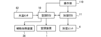
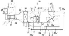
加湿空気供給装置は、車室内を空調する車両用の空調装置と、空調装置による冷却空気、加熱空気を使用して車室内に加湿空気を提供する加湿ユニットとを備えている。図1には、車両に搭載する場合の加湿空気供給装置100に関する制御構成の一例を示している。図2には、加湿ユニット4と空調装置1を備えた加湿空気供給装置100を示している。   The humidified air supply device includes an air conditioner for a vehicle that air-conditions a vehicle interior, and a humidification unit that provides humidified air to the vehicle interior using cooling air and heated air from the air conditioner. FIG. 1 shows an example of a control configuration relating to the humidified air supply device 100 when mounted on a vehicle. FIG. 2 shows a humidified air supply device 100 including the humidification unit 4 and the air conditioner 1.

加湿空気供給装置100は、車室内空調運転と、車室内空調運転と連動する加湿運転とを実施できる装置である。加湿空気供給装置100は、車室内を加湿対象空間とし、加湿ユニット4が空調装置1に連結されて設置された構成を有している。まず、空調装置1について説明する。   The humidification air supply device 100 is a device capable of performing a vehicle interior air-conditioning operation and a humidification operation interlocked with the vehicle interior air-conditioning operation. The humidification air supply device 100 has a configuration in which the interior of the vehicle is a humidification target space, and the humidification unit 4 is connected to the air conditioner 1 and installed. First, the air conditioner 1 will be described.

空調装置1は車室内の前方に設けられている。空調装置1は、送風ユニット2、空調ユニット3および冷凍サイクル5、空調ECU10を備えている。送風ユニット2は、空調ユニット3の空調ケース30内を流れる空気流を発生させる送風手段としての室内用ブロワ20を備えている。   The air conditioner 1 is provided in the front of the vehicle interior. The air conditioner 1 includes a blowing unit 2, an air conditioning unit 3, a refrigeration cycle 5, and an air conditioning ECU 10. The blower unit 2 includes an indoor blower 20 as a blower that generates an airflow flowing in the air conditioning case 30 of the air conditioning unit 3.

送風ユニット2の上流側には、内外気切替ケース設けられている。内外気切換ケースには、車室内の空気を取り入れる内気吸込口24と車室外の空気を取り入れる外気吸込口25とが形成されている。内気吸込口24および外気吸込口25の内側には、内外気切替ドア26が回動自在に設けられている。内外気切替ドア26は、サーボモータ等のアクチュエータにより駆動されて、吸込口モードを、車室内空気を循環する内気循環モード、車外空気を取り入れる外気導入モード等に切り替えることが可能である。   An inside / outside air switching case is provided upstream of the blower unit 2. The inside / outside air switching case is formed with an inside air suction port 24 for taking in air inside the vehicle compartment and an outside air suction port 25 for taking in air outside the vehicle compartment. Inside / outside air switching doors 26 are rotatably provided inside the inside air inlet 24 and the outside air inlet 25. The inside / outside air switching door 26 is driven by an actuator such as a servomotor, and can switch the suction port mode to an inside air circulation mode for circulating vehicle interior air, an outside air introduction mode for taking in outside air, and the like.

室内用ブロワ20は、ブロワケース、ファン、モータ21を有している。モータ21の回転速度はモータ21への印加電圧に応じて決定される。モータ21への印加電圧が空調ECU10からの制御信号に基づいて制御されることにより、室内用ブロワ20の送風量は制御される。   The indoor blower 20 has a blower case, a fan, and a motor 21. The rotation speed of the motor 21 is determined according to the voltage applied to the motor 21. By controlling the voltage applied to the motor 21 based on a control signal from the air conditioning ECU 10, the amount of air blown from the indoor blower 20 is controlled.

空調ケース30の内部には、車室内に空調空気を導く空気通路23が設けられている。空気通路23には、室内用ブロワ20よりも送風空気の下流側において、下流側に進むにしたがい順に、蒸発器55、エアミックスドア31、ヒータコア32が設置されている。ヒータコア32は、エンジンのウォータジャケットで暖められた冷却水が電動のウォータポンプによって循環する冷却水回路に設けられている。ヒータコア32は、内部を流れる冷却水を暖房用熱源として空調ケース30内を流れる空気を加熱する加熱装置である。   An air passage 23 that guides conditioned air into the vehicle interior is provided inside the air conditioning case 30. The evaporator 55, the air mix door 31, and the heater core 32 are installed in the air passage 23 in the order downstream of the blower air from the indoor blower 20 in the order of progressing toward the downstream side. The heater core 32 is provided in a cooling water circuit in which cooling water warmed by a water jacket of the engine is circulated by an electric water pump. The heater core 32 is a heating device that heats air flowing in the air-conditioning case 30 using cooling water flowing inside as a heating heat source.

空気通路23においてヒータコア32よりも空気流れの下流には、補助加熱装置38が設置されている。補助加熱装置38は、例えば、ニクロム線ヒータ、PTC(Positive Temperature Coefficient)ヒータを有する装置などの通電によって発熱する電気式ヒータである。補助加熱装置38は、ヒータコア32よりも下流において放熱によって空調ケース30内を流れる空気を加熱する。補助加熱装置38は、車載電池からの直流電源の供給を受ける。補助加熱装置38の運転は、空調ECU10による通電、非通電によって制御される。   An auxiliary heating device 38 is provided downstream of the heater core 32 in the air passage 23 in the air flow. The auxiliary heating device 38 is, for example, an electric heater that generates heat when energized, such as a device having a nichrome wire heater or a PTC (Positive Temperature Coefficient) heater. The auxiliary heating device 38 heats the air flowing in the air conditioning case 30 by heat radiation downstream of the heater core 32. The auxiliary heating device 38 receives supply of DC power from a vehicle-mounted battery. The operation of the auxiliary heating device 38 is controlled by energization and non-energization by the air conditioning ECU 10.

補助加熱装置38の一例であるPTCヒータは、通電発熱素子部を備え、通電発熱素子部に通電されることによって発熱し、周囲の空気を暖めることができる。この通電発熱素子部は、耐熱性を有する樹脂材料である、例えば、66ナイロンやポリブタジエンテレフタレートなどで成形された樹脂枠の中に複数個のPTC素子を嵌め込むことにより構成したものである。また、PTCヒータは、さらに通電発熱素子部からの発熱を伝達する熱交換フィン部を有してもよい。この熱交換フィン部は、アルミニウムの薄板を波形状に成形したコルゲートフィンと、このコルゲートフィンを一定の形状に保つとともにPTC素子や電極板との接触面積を確保するアルミニウムプレートと、をろう付け接合することにより構成したものである。   The PTC heater, which is an example of the auxiliary heating device 38, includes an energized heating element, generates heat when energized to the energized heating element, and heats the surrounding air. The energization heating element section is configured by fitting a plurality of PTC elements into a resin frame formed of a heat-resistant resin material, for example, 66 nylon, polybutadiene terephthalate, or the like. Further, the PTC heater may further include a heat exchange fin portion for transmitting heat generated from the energized heating element. The heat exchange fins are formed by brazing a corrugated fin made of a thin aluminum plate into a corrugated shape and an aluminum plate that maintains the corrugated fin in a constant shape and ensures a contact area with the PTC element and the electrode plate. It is constituted by doing.

空調ケース30の最も下流側には、デフロスタ開口部、フェイス開口部およびフット開口部が形成されている。デフロスタ開口部には、デフロスタダクト34が接続されており、デフロスタダクト34内には、車両のフロント窓ガラスの内面に向かって主に温風を吹き出すデフロスタ通路34aが設けられている。フェイス開口部には、フェイスダクト35が接続されており、フェイスダクト35内には、乗員の頭胸部に向かって主に冷風を吹き出すフェイス通路35aが設けられている。フット開口部には、フットダクト37が接続されており、フットダクト37内には、乗員の足元部に向かって主に温風を吹き出すフット通路37aが設けられている。   At the most downstream side of the air conditioning case 30, a defroster opening, a face opening, and a foot opening are formed. A defroster duct 34 is connected to the defroster opening, and a defroster passage 34a that mainly blows warm air toward the inner surface of the windshield of the vehicle is provided in the defroster duct 34. A face duct 35 is connected to the face opening, and in the face duct 35, a face passage 35a that mainly blows cold air toward the occupant's head and chest is provided. A foot duct 37 is connected to the foot opening, and in the foot duct 37, a foot passage 37a that mainly blows out warm air toward the feet of the occupant is provided.

空調ユニット3は、デフロスタ通路34aとフェイス通路35aとを開閉する第1吹出切替ドア33と、フット通路37aを開閉する第2吹出切替ドア36とを備えている。第1吹出切替ドア33、第2吹出切替ドア36は、サーボモータ等のアクチュエータによってそれぞれ駆動される。第1吹出切替ドア33、第2吹出切替ドア36は、車室内への吹出口モードをフェイスモード、バイレベルモード、フットモード、フットデフロスタモード、デフロスタモード等に切り替えることが可能である。   The air conditioning unit 3 includes a first blowout switching door 33 that opens and closes the defroster passage 34a and the face passage 35a, and a second blowout switching door 36 that opens and closes the foot passage 37a. The first outlet switching door 33 and the second outlet switching door 36 are each driven by an actuator such as a servomotor. The first air outlet switching door 33 and the second air outlet switching door 36 can switch the air outlet mode into the vehicle compartment to a face mode, a bi-level mode, a foot mode, a foot defroster mode, a defroster mode, or the like.

冷凍サイクル5は、圧縮機50、圧縮された冷媒を凝縮液化させる凝縮器51、気液分離器53、液冷媒を減圧膨張させる膨張弁54、減圧膨張された冷媒を蒸発気化させる蒸発器55、およびこれらを環状に接続する冷媒配管等を備えている。気液分離器53は、凝縮器51において凝縮液化された冷媒を気液分離し、液冷媒は下流に流下する。   The refrigeration cycle 5 includes a compressor 50, a condenser 51 for condensing and liquefying the compressed refrigerant, a gas-liquid separator 53, an expansion valve 54 for decompressing and expanding the liquid refrigerant, an evaporator 55 for evaporating the depressurized and expanded refrigerant, And a refrigerant pipe and the like for connecting these in a ring shape. The gas-liquid separator 53 separates the refrigerant condensed and liquefied in the condenser 51 into gas and liquid, and the liquid refrigerant flows downstream.

圧縮機50は、インバータにより回転数制御されて冷媒を圧縮する電動圧縮機である。圧縮機50は、内蔵された電動モータにより駆動され、回転数制御が可能であり、回転数に応じて冷媒吐出流量が可変である。圧縮機50はインバータにより周波数が調整された交流電圧が印加されてその電動モータの回転速度が制御される。インバータは車載電池から直流電源の供給を受け、空調ECU10により制御される。   The compressor 50 is an electric compressor whose rotational speed is controlled by an inverter to compress the refrigerant. The compressor 50 is driven by a built-in electric motor, is capable of controlling the number of revolutions, and has a variable refrigerant discharge flow rate according to the number of revolutions. An AC voltage whose frequency is adjusted by an inverter is applied to the compressor 50, and the rotation speed of the electric motor is controlled. The inverter is supplied with DC power from a vehicle-mounted battery, and is controlled by the air conditioning ECU 10.

凝縮器51は、エンジンコンパートメント等の車両が走行する際に生じる走行風を受け易い場所に設けられている。凝縮器51は、内部を流れる冷媒と室外ファン52により送風される外気および走行風とを熱交換する室外熱交換器である。蒸発器55は、室内用ブロワ20直後の通路全体を横断するように設置されており、室内用ブロワ20から吹き出された空気全部が通過するようになっている。蒸発器55は、内部を流れる冷媒と空気通路23を流れる空気との間で熱交換が行われて当該空気を冷却する空気冷却作用および自身を通過する空気を除湿する空気除湿作用を行う冷却装置である。   The condenser 51 is provided in a place, such as an engine compartment, where the vehicle is likely to receive a traveling wind generated when the vehicle travels. The condenser 51 is an outdoor heat exchanger that exchanges heat between the refrigerant flowing therein and the outside air and traveling wind blown by the outdoor fan 52. The evaporator 55 is installed so as to traverse the entire passage immediately after the indoor blower 20 so that all the air blown out from the indoor blower 20 passes. The evaporator 55 is a cooling device that exchanges heat between the refrigerant flowing therein and the air flowing through the air passage 23 to perform an air cooling function of cooling the air and an air dehumidifying function of dehumidifying the air passing therethrough. It is.

蒸発器55よりも下流側であってヒータコア32よりも上流側の通風路には、蒸発器55を通過した空気を、ヒータコア32を通る空気とヒータコア32を迂回する空気の風量比率を調整できるエアミックスドア31が設けられている。エアミックスドア31は、アクチュエータ等によりそのドア本体の位置を変化させて、空調ケース30内の蒸発器55よりも下流の通路の一部を塞ぐことで、車室内へ吹き出す空気の吹出温度を調整する温度調整手段である。   In the ventilation passage downstream of the evaporator 55 and upstream of the heater core 32, air that has passed through the evaporator 55 can be used to adjust the air volume ratio between the air passing through the heater core 32 and the air bypassing the heater core 32. A mix door 31 is provided. The air mixing door 31 changes the position of the door body by an actuator or the like and closes a part of a passage downstream of the evaporator 55 in the air-conditioning case 30 to adjust the temperature of the air blown into the vehicle compartment. Temperature adjusting means.

操作部110は、加湿空気供給装置100の運転中に表示状態になる動作表示部としての表示画面部と各種スイッチとを有している。表示画面部は、空調ECU10や加湿ECU11からの命令信号によって表示状態または非表示状態に制御される。   The operation unit 110 has a display screen unit as an operation display unit that becomes a display state during operation of the humidified air supply device 100, and various switches. The display screen is controlled to a display state or a non-display state by a command signal from the air conditioning ECU 10 or the humidification ECU 11.

空調ECU10は、操作部110の操作によって設定された、マニュアル運転による指令や自動運転の設定温度に応じて、室内用ブロワ20による送風量と空調空気の温度とを制御する。空調装置1の運転、停止および設定温度などの操作信号、各種センサの検出信号が入力されると、空調ECU10は車両ECU、加湿ECU11等と通信する。空調ECU10は、演算結果に基づいて、圧縮機50、室内用ブロワ20、室外ファン52、エアミックスドア31、補助加熱装置38、内外気切替ドア26、吹出口切替等といった各機器の運転を制御する。空調ECU10は、マイクロコンピュータと、車室内前方に設けられた操作部110における各種スイッチからの信号や、各種センサからのセンサ信号が入力される入力回路と、各種アクチュエータに出力信号を送る出力回路と、を備えている。空調ECU10は、水温センサ62によって検出されたエンジン冷却水の温度である冷却水温度に関わる温度情報を取得する。水温センサ62は温度に応じて抵抗値が変化するサーミスタである。   The air-conditioning ECU 10 controls the amount of air blown by the indoor blower 20 and the temperature of the conditioned air according to a manual operation command or an automatic operation set temperature set by the operation of the operation unit 110. The air conditioning ECU 10 communicates with the vehicle ECU, the humidification ECU 11 and the like when operation signals such as operation, stop, and set temperature of the air conditioner 1 and detection signals of various sensors are input. The air-conditioning ECU 10 controls the operation of each device such as the compressor 50, the indoor blower 20, the outdoor fan 52, the air mix door 31, the auxiliary heating device 38, the inside / outside air switching door 26, and the outlet switching based on the calculation result. I do. The air-conditioning ECU 10 includes a microcomputer, an input circuit for inputting signals from various switches and sensor signals from various sensors in an operation unit 110 provided in the front of the vehicle cabin, and an output circuit for sending output signals to various actuators. , Is provided. The air-conditioning ECU 10 acquires temperature information related to the cooling water temperature, which is the temperature of the engine cooling water detected by the water temperature sensor 62. The water temperature sensor 62 is a thermistor whose resistance changes according to the temperature.

空調ECU10は、その出力側に接続された各種空調用機器を制御する制御手段が一体に構成された制御装置である。各空調用機器の作動を制御するハードウェアおよびソフトウェアは、各空調用構成機器の作動を制御する制御手段を構成している。空調ECU10はプログラムにしたがって動作するマイコンのようなデバイスを主なハードウェア要素として備える。空調ECU10は、送受信部と、各空調用機器と各種センサとが接続されるインターフェース部と、演算処理部と、記憶部とを少なくとも備えている。記憶部は、コンピュータによって読み取り可能なプログラムを非一時的に格納する非遷移的実体的記憶媒体である。記憶媒体は、半導体メモリまたは磁気ディスクなどによって提供されうる。演算処理部は、演算処理装置であり、インターフェース部を通して各種センサから取得した環境情報と、記憶部に記憶された制御特性マップやデータとを用いて所定のプログラムにしたがった判定処理や演算処理を行う。演算処理部は、空調ECU10における演算実行部であり判定処理実行部である。インターフェース部は、演算処理部による判定結果、演算結果に基づいて前述の各調整機器を操作する。したがって、インターフェース部は、制御装置における入力部および制御出力部である。   The air-conditioning ECU 10 is a control device integrally formed with control means for controlling various air-conditioning devices connected to the output side. The hardware and software for controlling the operation of each air-conditioning device constitute control means for controlling the operation of each air-conditioning component. The air-conditioning ECU 10 includes, as main hardware elements, a device such as a microcomputer that operates according to a program. The air conditioning ECU 10 includes at least a transmission / reception unit, an interface unit for connecting each air conditioning device and various sensors, an arithmetic processing unit, and a storage unit. The storage unit is a non-transitional substantial storage medium that temporarily stores a computer-readable program. The storage medium can be provided by a semiconductor memory, a magnetic disk, or the like. The arithmetic processing unit is an arithmetic processing unit, and performs determination processing and arithmetic processing according to a predetermined program using environmental information acquired from various sensors through the interface unit and control characteristic maps and data stored in the storage unit. Do. The calculation processing unit is a calculation execution unit and a determination processing execution unit in the air conditioning ECU 10. The interface unit operates each of the above-described adjustment devices based on the determination result and the calculation result by the calculation processing unit. Therefore, the interface unit is an input unit and a control output unit in the control device.

図2に示すように、加湿ユニット4は、ユニットケース40と吸着材モジュール41と流路切替装置とを備えている。ユニットケース40は、吸着材モジュール41と流路切替装置を収容し、空調ユニット3に連結されている。ユニットケース40の内部には、冷却用通路40aと加熱用通路40bと下流側通路40cが設けられている。冷却用通路40aと加熱用通路40bは下流側において下流側通路40cに接続されている。ユニットケース40の外形は、箱体状でもよいし、細長いダクト状でもよい。   As shown in FIG. 2, the humidifying unit 4 includes a unit case 40, an adsorbent module 41, and a flow path switching device. The unit case 40 houses the adsorbent module 41 and the flow path switching device, and is connected to the air conditioning unit 3. Inside the unit case 40, a cooling passage 40a, a heating passage 40b, and a downstream passage 40c are provided. The cooling passage 40a and the heating passage 40b are connected to the downstream passage 40c on the downstream side. The outer shape of the unit case 40 may be a box shape or an elongated duct shape.

冷却用通路40aは、空調ケース30内において蒸発器55とエアミックスドア31との間の空気通路に接続されている。冷却用通路40aは、蒸発器55によって冷却された空気を加湿ユニット4内に分流させることが可能な流路を構成する。加湿ユニット4は、冷却用通路40aを開閉する第1ドア42を有している。   The cooling passage 40 a is connected to an air passage between the evaporator 55 and the air mix door 31 in the air conditioning case 30. The cooling passage 40 a constitutes a flow path that allows the air cooled by the evaporator 55 to be diverted into the humidification unit 4. The humidification unit 4 has a first door 42 that opens and closes the cooling passage 40a.

加熱用通路40bは、空調ケース30内においてヒータコア32よりも下流に接続されている。加熱用通路40bは、ヒータコア32によって加熱された空気を加湿ユニット4内に分流させることが可能な流路を構成する。加湿ユニット4は、加熱用通路40bを開閉する第2ドア43を有している。   The heating passage 40 b is connected downstream of the heater core 32 in the air conditioning case 30. The heating passage 40 b constitutes a flow passage that can divide the air heated by the heater core 32 into the humidification unit 4. The humidification unit 4 has a second door 43 that opens and closes the heating passage 40b.

下流側通路40cは、下流端においてフェイスダクト35に接続されている。下流側通路40cには吸着材モジュール41が設置されている。下流側通路40cを流下する空気は、吸着材モジュール41を通過した後、フェイス通路35aを介して乗員の頭胸部に向かって吹き出される。   The downstream passage 40c is connected to the face duct 35 at a downstream end. An adsorbent module 41 is provided in the downstream passage 40c. After passing through the adsorbent module 41, the air flowing down the downstream passage 40c is blown out toward the occupant's head and chest through the face passage 35a.

吸着材モジュール41は、吸着材を担持させた複数の金属製の板状部材を間隔をあけて積層設置し、板状部材と板状部材との間に送風空気を通過させる通路を備えている。吸着材モジュール41では、このように吸着材を担持させた複数の板状部材を積層設置する構成により、送風空気と吸着材との接触面積を増加させることができる。吸着材モジュール41では、吸着材として、有機系材料の高分子吸着材、無機系材料のゼロライト、シリカゲル等の吸湿材料を採用している。   The adsorbent module 41 is provided with a plurality of metal plate-like members carrying an adsorbent, which are stacked and arranged at intervals, and a passage for passing the blast air between the plate-like members. . In the adsorbent module 41, the contact area between the blown air and the adsorbent can be increased by the configuration in which the plurality of plate-like members carrying the adsorbent are stacked and installed. In the adsorbent module 41, a polymer adsorbent made of an organic material, zero light made of an inorganic material, and a moisture absorbing material such as silica gel are used as the adsorbent.

下流側通路40cは、フェイス通路35aに合流することなく、車室内に直接連通する構成でもよい。この場合、下流側通路40cを流下する空気は、吸着材モジュール41を通過した後、車室内に吹き出される。また、下流側通路40cはフェイス通路35aとデフロスタ通路34aとの両方に繋がるように分岐し、加湿ユニット4はフェイス通路35aに連通する場合とデフロスタ通路34aに連通する場合とに切り替え可能な手段を有する構成でもよい。この場合、下流側通路40cを流下する空気は、吸着材モジュール41を通過した後、加湿空気を供給する場合にはフェイス通路35aを介して車室内に吹き出され、除湿空気を供給する場合にはデフロスタ通路34aを介して車室内に吹き出される。   The downstream passage 40c may be configured to directly communicate with the vehicle interior without joining the face passage 35a. In this case, the air flowing down the downstream passage 40c is blown into the vehicle interior after passing through the adsorbent module 41. Further, the downstream passage 40c is branched so as to be connected to both the face passage 35a and the defroster passage 34a, and the humidifying unit 4 is provided with a means capable of switching between a case where the humidification unit 4 is connected to the face passage 35a and a case where the humidification unit 4 is connected to the defroster passage 34a. May be provided. In this case, the air flowing down the downstream side passage 40c passes through the adsorbent module 41 and is blown into the vehicle interior through the face passage 35a when supplying humidified air, and when supplying dehumidified air. The air is blown into the vehicle interior via the defroster passage 34a.

加湿空気供給装置100は、加湿ユニット4の運転を制御する加湿ECU11を備えている。加湿ECU11には、操作部110から出力される運転指令信号、空調ECU10からの通信信号等が入力される。加湿ECU11と空調ECU10とは、互いに情報、指令を通信する関係にある。操作部110は、空調装置1の運転に関する指令信号を空調ECU10に送るための各種スイッチに加え、加湿ユニット4を起動、停止するための運転スイッチ等を含んでいる。   The humidification air supply device 100 includes a humidification ECU 11 that controls the operation of the humidification unit 4. An operation command signal output from the operation unit 110, a communication signal from the air conditioning ECU 10, and the like are input to the humidification ECU 11. The humidification ECU 11 and the air-conditioning ECU 10 have a relationship of communicating information and commands with each other. The operation unit 110 includes an operation switch for starting and stopping the humidifying unit 4 in addition to various switches for sending a command signal relating to the operation of the air conditioner 1 to the air conditioning ECU 10.

加湿ECU11は、その出力側に接続された加湿ユニット4の各種機器を制御する制御手段が一体に構成された制御装置である。加湿ユニット4の各種機器の作動を制御するハードウェアおよびソフトウェアは、制御手段を構成している。加湿ECU11は、プログラムにしたがって動作するマイコンのようなデバイスを主なハードウェア要素として備える。加湿ECU11は、加湿ユニット4の各種機器、操作部110および空調ECU10が接続されるインターフェース部と演算処理部と、記憶部とを少なくとも備える。演算処理部は、インターフェース部を通して所定のセンサの検出信号、空調ECU10からの通信信号等を用いて、記憶部に記憶された制御特性マップ、データ、所定のプログラム等にしたがった判定処理や演算処理を行う。演算処理部は、加湿ECU11における判定処理実行部である。インターフェース部は、演算処理部による判定結果、演算結果に基づいて、第1ドア42、第2ドア43を含む加湿ユニット4の各種機器を操作する。インターフェース部は、加湿ECU11における入力部および制御出力部である。   The humidification ECU 11 is a control device integrally formed with control means for controlling various devices of the humidification unit 4 connected to the output side. The hardware and software for controlling the operation of various devices of the humidification unit 4 constitute control means. The humidification ECU 11 includes, as main hardware elements, a device such as a microcomputer that operates according to a program. The humidification ECU 11 includes at least an interface unit to which various devices of the humidification unit 4, the operation unit 110, and the air conditioning ECU 10 are connected, an arithmetic processing unit, and a storage unit. The arithmetic processing unit uses a detection signal of a predetermined sensor through the interface unit, a communication signal from the air-conditioning ECU 10, and the like to perform a determination process and an arithmetic process according to a control characteristic map, data, a predetermined program, and the like stored in the storage unit. I do. The arithmetic processing unit is a determination processing execution unit in the humidification ECU 11. The interface unit operates various devices of the humidifying unit 4 including the first door 42 and the second door 43 based on the determination result and the calculation result by the calculation processing unit. The interface unit is an input unit and a control output unit in the humidification ECU 11.

また、加湿ECU11は、例えば、空調装置1の各空調用機器の作動を制御する空調用制御装置の一部として、または空調用制御装置と一体的に構成される制御装置であってもよい。   Further, the humidification ECU 11 may be, for example, a control device configured as a part of an air conditioning control device that controls the operation of each air conditioning device of the air conditioning device 1 or integrated with the air conditioning control device.

加湿ユニット4では、脱離時に、ヒータコア32によって、またはヒータコア32と補助加熱装置38の両方によって加熱された空気が、第2ドア43によって開状態である加熱用通路40bに流入する。加熱用通路40bに流入した空気は吸着材モジュール41を通過するときに水分を貯えてからフェイス通路35aを流下する。このとき第1ドア42は冷却用通路40aを閉状態に制御している。加湿ユニット4は、この脱離時の空気流れを実施することにより、乗員または車室内に対して加湿空気を供給できる。   In the humidification unit 4, at the time of desorption, the air heated by the heater core 32 or by both the heater core 32 and the auxiliary heating device 38 flows into the heating passage 40 b opened by the second door 43. The air that has flowed into the heating passage 40b stores moisture when passing through the adsorbent module 41, and then flows down the face passage 35a. At this time, the first door 42 controls the cooling passage 40a to be closed. The humidifying unit 4 can supply humidified air to the occupant or the passenger compartment by performing the air flow at the time of desorption.

加湿ユニット4では、吸着素子に水分が吸着される吸湿時に、空調ユニット3の蒸発器55によって冷却された空気が、第1ドア42によって開状態である冷却用通路40aに流入し、吸着材モジュール41の通過時に水分を放出し、フェイス通路35aを流下する。このとき第2ドア43は加熱用通路40bを閉状態に制御し、吸着素子は放出された水分を吸着する。加湿ユニット4は、この吸湿時の空気流れを実施することにより、車室内に対して除湿空気を供給する。   In the humidifying unit 4, when moisture is absorbed by the adsorption element, the air cooled by the evaporator 55 of the air conditioning unit 3 flows into the cooling passage 40 a opened by the first door 42 and the adsorbent module At the time of passage through 41, moisture is released and flows down the face passage 35a. At this time, the second door 43 controls the heating passage 40b to the closed state, and the adsorption element adsorbs the released moisture. The humidifying unit 4 supplies the dehumidified air to the vehicle interior by performing the air flow at the time of absorbing moisture.

加湿空気供給装置100の作動について説明する。加湿空気供給装置100は、加湿ユニット4が運転していない状態において空調装置1による車室内空調運転と、加湿ユニット4と空調装置1とが連動して車室内に加湿空気を供給する加湿運転とを実施する装置である。加湿空気供給装置100は、例えば、乗員の操作によって操作部110に含まれる加湿運転スイッチがオン状態になると加湿運転を実施可能な状態になる。例えば、加湿運転は、冬季のように比較的外気温が低く、車室内が乾燥しやすいときに作動することが多い。加湿運転スイッチがオン状態になると、加湿ECU11は、冷却用通路40aを開放する状態と加熱用通路40bを開放する状態とを例えば所定時間毎に交互に切り替えるように、第1ドア42および第2ドアを制御する。これにより、空気通路23を流れ空気の一部が冷却用通路40aを流下する流路と加熱用通路40bを流下する流路とが所定時間毎に切り替えられることになる。   The operation of the humidified air supply device 100 will be described. The humidifying air supply device 100 performs a humidifying operation in which the humidifying unit 4 is not operating and the humidifying unit 4 and the air conditioner 1 work together to supply humidified air into the vehicle cabin. It is a device for implementing. For example, when the humidification operation switch included in the operation unit 110 is turned on by an occupant's operation, the humidification air supply device 100 enters a state in which the humidification operation can be performed. For example, the humidifying operation often operates when the outside temperature is relatively low and the vehicle interior is easily dried, such as in winter. When the humidification operation switch is turned on, the humidification ECU 11 switches the first door 42 and the second door 42 so as to alternately switch between a state in which the cooling passage 40a is opened and a state in which the heating passage 40b is opened, for example, at predetermined time intervals. Control the door. Thus, the flow path in which a part of the air flowing down the air passage 23 flows down the cooling passage 40a and the flow path flowing down the heating passage 40b are switched at predetermined intervals.

送風ユニット2が送風しヒータコア32や補助加熱装置38が通過空気を加熱しているときに、加湿ECU11が第1ドア42を閉状態に制御しかつ第2ドア43を開状態に制御すると、ヒータコア32などによって暖められた空気は加熱用通路40bに流入する。このとき補助加熱装置38を通過後の空気の温度が車室内空気の温度よりも所定温度、例えば5℃程度高くなるように、補助加熱装置38の出力は制御されることが好ましい。   When the humidification ECU 11 controls the first door 42 to be closed and the second door 43 to be opened while the blowing unit 2 is blowing and the heater core 32 and the auxiliary heating device 38 are heating the passing air, the heater core The air heated by 32 or the like flows into the heating passage 40b. At this time, the output of the auxiliary heating device 38 is preferably controlled so that the temperature of the air after passing through the auxiliary heating device 38 becomes higher than the temperature of the air in the vehicle compartment by a predetermined temperature, for example, about 5 ° C.

ヒータコア32や補助加熱装置38を通過後の送風空気は、加熱用通路40bを通じて吸着材モジュール41に流入する。この際、加熱されて温度上昇した空気の相対湿度は、車室内の空気の相対湿度よりも低下している。したがって、加熱されて相対湿度が下がった空気を吸着材モジュール41の吸着材に接触させることで吸着材に吸着している水分が空気に脱離しやすい状況となる。つまり、加熱によって相対湿度が下げられた空気は、吸着材が保持している水分を含みやすいため、吸着材モジュール41を流出後の空気は十分に加湿された加湿空気になってから乗員に向けて供給される。   The blown air that has passed through the heater core 32 and the auxiliary heating device 38 flows into the adsorbent module 41 through the heating passage 40b. At this time, the relative humidity of the heated air whose temperature has risen is lower than the relative humidity of the air in the vehicle cabin. Therefore, by bringing the heated air having a lowered relative humidity into contact with the adsorbent of the adsorbent module 41, the water adsorbed on the adsorbent is easily released into the air. That is, since the air whose relative humidity has been reduced by the heating tends to contain the moisture held by the adsorbent, the air after flowing out of the adsorbent module 41 becomes sufficiently humidified humidified air before being directed to the occupant. Supplied.

この脱離時には、吸着材モジュール41に供給する前の空気をヒータコア32や補助加熱装置38で加熱するため、当該空気を迅速に温度上昇させることができる。さらに、空気温度が迅速に上昇したことにより、空気の相対湿度を迅速に下げることができるため、吸着材モジュール41での水分脱離が活発に行われ、吸着材モジュール41を流出後の空気の相対湿度を迅速に高めることができる。   During the desorption, the air before being supplied to the adsorbent module 41 is heated by the heater core 32 and the auxiliary heating device 38, so that the temperature of the air can be quickly raised. Furthermore, since the air temperature rises quickly, the relative humidity of the air can be quickly lowered, so that the desorption of water in the adsorbent module 41 is actively performed, and the air after flowing out of the adsorbent module 41 is discharged. The relative humidity can be increased quickly.

送風ユニット2が送風し蒸発器55が通過空気を冷却しているときに、加湿ECU11が第1ドア42を開状態に制御しかつ第2ドア43を閉状態に制御すると、蒸発器55を通過して冷却された空気は冷却用通路40aに流入する。このとき蒸発器55を通過後の温度低下した空気の相対湿度は、車室内の空気の相対湿度よりも上昇している。したがって、車室内の空気に対して相対湿度が高まった空気を吸着材に接触させることができるので、空気の水分が吸着材に吸着しやすい状況となる。つまり、蒸発器55によって相対湿度が上げられた空気は、吸着材に水分を吸着させやすく、吸着材モジュール41を流出後の空気は十分に除湿された除湿空気になってから車室内に向けて供給される。   When the humidification ECU 11 controls the first door 42 to be open and the second door 43 to be closed while the blower unit 2 is blowing and the evaporator 55 is cooling the passing air, the evaporator 55 passes through the evaporator 55. The cooled air flows into the cooling passage 40a. At this time, the relative humidity of the temperature-reduced air after passing through the evaporator 55 is higher than the relative humidity of the air in the vehicle cabin. Therefore, the air having a higher relative humidity with respect to the air in the vehicle compartment can be brought into contact with the adsorbent, so that the moisture of the air is easily adsorbed on the adsorbent. In other words, the air whose relative humidity has been raised by the evaporator 55 can easily adsorb moisture to the adsorbent, and the air flowing out of the adsorbent module 41 becomes sufficiently dehumidified air before being directed to the vehicle interior. Supplied.

この吸湿時には、吸着材モジュール41に供給する前の空気を蒸発器55で冷却するため、当該空気を迅速に温度低下させることができる。さらに、空気温度が迅速に低下することにより、空気の相対湿度を迅速に高めることができるため、吸着材モジュール41での水分吸着が活発に行われ、吸着材モジュール41を流出後の空気の相対湿度を迅速に低下させることができる。   During this moisture absorption, the air before being supplied to the adsorbent module 41 is cooled by the evaporator 55, so that the temperature of the air can be rapidly lowered. Further, since the relative humidity of the air can be quickly increased by rapidly lowering the air temperature, moisture adsorption in the adsorbent module 41 is actively performed, and the relative humidity of the air after flowing out of the adsorbent module 41 is increased. Humidity can be reduced quickly.

次に、加湿空気供給装置100による加湿運転に関する制御について図3のフローチャートを参照して説明する。加湿空気供給装置100が備える制御装置は、例えば乗員の操作によって加湿運転スイッチがオンされると図3のフローチャートにしたがった処理を開始する。図3のステップS10、ステップS20における処理は、空調ECU10や加湿ECU11における演算処理部が実行する。   Next, control regarding the humidification operation by the humidification air supply device 100 will be described with reference to the flowchart in FIG. The control device included in the humidified air supply device 100 starts the processing according to the flowchart of FIG. 3 when the humidification operation switch is turned on by, for example, the operation of the occupant. The processing in steps S10 and S20 in FIG. 3 is executed by the arithmetic processing unit in the air conditioning ECU 10 and the humidification ECU 11.

まず演算処理部はステップS10で、水温センサ62による検出信号を取得し、この検出信号に基づいて現在の冷却水温度が第1の閾温度以上であるか否かを判定する。現在の冷却水温度が第1の閾温度未満であることは、ヒータコア32によって加熱された後の空気の温度について、吸着材に吸着されている水分を脱離できる加湿可能温度条件が成立しない場合の一例である。   First, in step S10, the arithmetic processing unit acquires a detection signal from the water temperature sensor 62, and determines whether or not the current cooling water temperature is equal to or higher than a first threshold temperature based on the detection signal. The fact that the current cooling water temperature is lower than the first threshold temperature means that the temperature of the air heated by the heater core 32 does not satisfy the humidification-possible temperature condition capable of desorbing the moisture adsorbed by the adsorbent. This is an example.

ステップS10では一例として、ヒータコア32によって加熱された後の空気温度が40℃以上であるか否かを判定する。加熱後の空気温度がステップS10において40℃以上であると判定した場合はステップS40において加湿モード処理を実行する。加湿モード処理において、空調ECU10は室内用ブロワ20を運転し、加湿ECU11は冷却用通路40aが閉じるように第1ドア42を制御し加熱用通路40bが開くように第2ドア43を制御する。このときに送風ユニット2が空気通路23に取り入れる空気は外気、内気またはその両方のいずれであってもよい。ヒータコア32によって加熱された空気は、空気通路23から加熱用通路40bに分流し、加熱用通路40bから下流側通路40cを流下する過程で吸着材モジュール41において脱離した水分を含んで加湿される。吸着材モジュール41を流出後の加湿空気は車室内または乗員に向けて供給される。加湿ECU11は加湿モードの実施後、ステップS50において吸湿モード処理を実行する。   In step S10, for example, it is determined whether the air temperature after being heated by the heater core 32 is equal to or higher than 40 ° C. If it is determined in step S10 that the air temperature after heating is equal to or higher than 40 ° C., a humidification mode process is executed in step S40. In the humidification mode processing, the air conditioning ECU 10 operates the indoor blower 20, and the humidification ECU 11 controls the first door 42 so that the cooling passage 40a is closed and controls the second door 43 so that the heating passage 40b is opened. At this time, the air taken into the air passage 23 by the blower unit 2 may be outside air, inside air, or both. The air heated by the heater core 32 is diverted from the air passage 23 to the heating passage 40b, and is humidified by containing the water desorbed in the adsorbent module 41 in the process of flowing down from the heating passage 40b to the downstream passage 40c. . The humidified air flowing out of the adsorbent module 41 is supplied to the passenger compartment or the occupant. After performing the humidification mode, the humidification ECU 11 executes a moisture absorption mode process in step S50.

吸湿モード処理において、空調ECU10は室内用ブロワ20を運転し、加湿ECU11は冷却用通路40aが開くように第1ドア42を制御し加熱用通路40bが閉じるように第2ドア43を制御する。このときも送風ユニット2が空気通路23に取り入れる空気は外気、内気またはその両方のいずれであってもよい。蒸発器55を通過した空気は、空気通路23から冷却用通路40aに分流し、冷却用通路40aから下流側通路40cを流下する過程で吸着材モジュール41において水分が吸着されて除湿される。吸着材モジュール41を流出後の除湿空気は車室内に供給される。加湿空気供給装置100は、加湿モードと吸湿モードとを順に実行した後はステップS10に戻り、以降の処理を継続する。   In the moisture absorption mode processing, the air conditioning ECU 10 operates the indoor blower 20, and the humidification ECU 11 controls the first door 42 so that the cooling passage 40a is opened and controls the second door 43 so that the heating passage 40b is closed. At this time, the air taken into the air passage 23 by the blower unit 2 may be outside air, inside air, or both. The air that has passed through the evaporator 55 is diverted from the air passage 23 to the cooling passage 40a, and in the process of flowing down from the cooling passage 40a to the downstream passage 40c, moisture is adsorbed and dehumidified in the adsorbent module 41. The dehumidified air flowing out of the adsorbent module 41 is supplied to the vehicle interior. After sequentially executing the humidification mode and the moisture absorption mode, the humidified air supply device 100 returns to step S10 and continues the subsequent processing.

ステップS10においてヒータコア32で加熱後の空気温度が40℃未満であると判定した場合は、演算処理部はステップS20において吸着材モジュール41において水分を脱離させるために必要な熱量を算出する。例えば演算処理部は、記憶部に記憶された特性マップやデータに基づいて、吸着材に吸着されている水分を脱離できる加湿可能温度を算出しあるいは記憶部に記憶されたデータから加湿可能温度を取得する。演算処理部は、この加湿可能温度とヒータコア32で加熱後の空気温度との温度差を算出し、補助加熱装置38によって加熱される空気の流量と温度差とを用いて、空気の温度をこの温度差分、上昇させるために必要な熱量を算出する。   If it is determined in step S10 that the air temperature after heating by the heater core 32 is lower than 40 ° C., the arithmetic processing unit calculates the amount of heat necessary for the adsorbent module 41 to desorb moisture in step S20. For example, the arithmetic processing unit calculates the humidification temperature at which the moisture adsorbed on the adsorbent can be desorbed based on the characteristic map and data stored in the storage unit, or calculates the humidification temperature from the data stored in the storage unit. To get. The arithmetic processing unit calculates a temperature difference between the humidification possible temperature and the air temperature after heating by the heater core 32, and calculates the temperature of the air using the flow rate and the temperature difference of the air heated by the auxiliary heating device 38. Calculate the temperature difference and the amount of heat required to raise it.

空調ECU10は、ステップS30において、必要な熱量を加湿ECU11と通信して取得し、この必要な熱量を出力できるように補助加熱装置38へ供給する電力を制御して補助加熱装置38を運転する。そして、前述のステップS40、ステップS50を順に実行した後、ステップS10に進む。このようにステップS10、S20、S30、S40を順に実行する処理により、冷却水温度が高くない場合でも、補助加熱装置38によって必要な熱量を得て加熱された空気が加熱用通路40bに流入して吸着材モジュール41の通過時に吸着材の水分を脱離させることができる。このように吸着材モジュール41に供給される空気が加湿可能温度であるため、吸着材モジュール41の通過時に吸着材が水分を放出できるので、ヒータコア32が加熱能力不足である状況であっても加湿モードを実施することができる。   In step S30, the air-conditioning ECU 10 obtains the required amount of heat by communicating with the humidification ECU 11, controls the power supplied to the auxiliary heating device 38 to output the required amount of heat, and operates the auxiliary heating device 38. Then, after the above-described steps S40 and S50 are sequentially performed, the process proceeds to step S10. As described above, by performing the steps S10, S20, S30, and S40 in sequence, even when the cooling water temperature is not high, the air heated by obtaining the necessary amount of heat by the auxiliary heating device 38 flows into the heating passage 40b. Thus, the moisture of the adsorbent can be desorbed when passing through the adsorbent module 41. Since the air supplied to the adsorbent module 41 is at the humidifying temperature, the adsorbent can release moisture when passing through the adsorbent module 41, so that even if the heater core 32 has insufficient heating capacity, the humidification is possible. Mode can be implemented.

第1実施形態の加湿空気供給装置100がもたらす作用効果について説明する。加湿空気供給装置100は、車室内に送風する空気を加熱する加熱装置を有する空調装置1と、加熱装置によって加熱された空気を加熱可能な補助加熱装置38と、加湿ユニット4と、補助加熱装置の運転と加湿ユニットの運転とを制御する制御装置とを備える。加湿ユニット4は、空気に含まれる水分を吸着材に吸湿することおよび吸着材に吸湿された水分を車室内に提供する空気に対して放出することを実施可能である。制御装置は、加熱装置を通過後の空気温度について加湿可能温度条件が不成立である場合に、補助加熱装置38を制御して加熱装置を通過後の空気を加熱し、加湿ユニットを制御して補助加熱装置38によって加熱された空気を吸着材に供給する。   The operation and effect provided by the humidified air supply device 100 of the first embodiment will be described. The humidified air supply device 100 includes an air conditioner 1 having a heating device for heating air blown into the vehicle interior, an auxiliary heating device 38 capable of heating the air heated by the heating device, a humidifying unit 4, and an auxiliary heating device. And a control device for controlling the operation of the humidifying unit. The humidifying unit 4 is capable of absorbing the moisture contained in the air by the adsorbent and discharging the moisture absorbed by the adsorbent to the air provided in the vehicle interior. The control device controls the auxiliary heating device 38 to heat the air after passing the heating device, and controls the humidification unit to control the humidification unit when the humidification possible temperature condition for the air temperature after passing the heating device is not satisfied. The air heated by the heating device 38 is supplied to the adsorbent.

この加湿空気供給装置100によれば、空調装置1が備える加熱装置を通過後の空気温度について加湿可能温度条件が成立していない場合に、補助加熱装置38によって補充的に加熱した空気を吸着材に供給できる。加湿空気供給装置100は、例えば空調装置1における空気加熱能力が不足している状況など、車両における様々な状況にわたって加湿空気を供給する加湿モードを実施できる。したがって、車両用の空調装置1において温風を供給できる熱量を得にくい状態であっても加湿空気を供給可能な加湿空気供給装置100を提供できる。   According to the humidified air supply device 100, when the humidification temperature condition is not satisfied for the air temperature after passing through the heating device provided in the air conditioner 1, the air supplementarily heated by the auxiliary heating device 38 is adsorbed. Can be supplied. The humidification air supply device 100 can execute a humidification mode in which humidification air is supplied over various conditions in the vehicle, such as a condition in which the air heating capacity of the air conditioner 1 is insufficient. Therefore, it is possible to provide the humidified air supply device 100 that can supply the humidified air even in a state where it is difficult to obtain the amount of heat that can supply the hot air in the vehicle air conditioner 1.

加熱装置は、エンジンの冷却水が流通するヒータコア32である。補助加熱装置38は、通電によって発熱する電気式ヒータである。制御装置は、加湿可能温度条件が成立していない場合に、ヒータコア32を通過後の空気を加熱するように電気式ヒータを制御する(ステップS10,S20,S30)。さらに制御装置は電気式ヒータによって加熱された空気を吸着材に供給するように加湿ユニット4を制御する(ステップS40)。   The heating device is a heater core 32 through which cooling water for the engine flows. The auxiliary heating device 38 is an electric heater that generates heat when energized. The control device controls the electric heater to heat the air after passing through the heater core 32 when the humidification possible temperature condition is not satisfied (steps S10, S20, S30). Further, the control device controls the humidification unit 4 so as to supply the air heated by the electric heater to the adsorbent (step S40).

この加湿空気供給装置100によれば、エンジンの冷却水温が低い場合に、電気式ヒータによって加熱された空気を吸着材に供給して加湿モードを実施できる。これにより、エンジン始動直後やエンジンが暖まるまでの期間においても、乗員の要望や車室内の湿度環境改善に寄与する加湿空気供給装置100を提供できる。   According to the humidified air supply device 100, when the cooling water temperature of the engine is low, the air heated by the electric heater can be supplied to the adsorbent to execute the humidified mode. This makes it possible to provide the humidified air supply device 100 that contributes to the demands of the occupants and the improvement of the humidity environment in the passenger compartment even immediately after the engine is started or until the engine warms up.

さらに制御装置は、加湿可能温度条件が成立していない場合に、吸着材に供給する空気が加湿可能温度条件を満たす温度になるために必要な熱量を算出し、電気式ヒータに通電する電力を必要な熱量を確保する値に制御する(ステップS10〜S30)。このステップS10〜S30の処理によれば、電気式ヒータに通電する電力値を、加湿モードを実施可能な必要な熱量に対する不足分に抑えることができる。第1実施形態の加湿空気供給装置100は、電気式ヒータによる電力的なエネルギ消費を抑えた加湿運転の実施によって車両の燃費または電費の低下抑制に寄与する。   Further, when the humidifying temperature condition is not satisfied, the control device calculates the amount of heat required for the air supplied to the adsorbent to reach a temperature satisfying the humidifying temperature condition, and reduces the electric power supplied to the electric heater. Control is performed to a value that secures the required amount of heat (steps S10 to S30). According to the processing in steps S10 to S30, the electric power value to be supplied to the electric heater can be suppressed to a shortage with respect to a necessary amount of heat capable of performing the humidification mode. The humidified air supply device 100 of the first embodiment contributes to suppression of a decrease in vehicle fuel efficiency or power consumption by performing a humidification operation in which electric energy consumption by an electric heater is suppressed.

(第2実施形態)
第2実施形態の加湿空気供給装置100について図4〜図7を参照して説明する。第2実施形態において、第1実施形態に係る図面と同一符号を付した構成部品やステップ、説明しない構成は、第1実施形態と同様であり、同様の作用効果を奏するものである。第2実施形態では、第1実施形態と異なる部分のみ説明する。
(2nd Embodiment)
A humidified air supply device 100 according to a second embodiment will be described with reference to FIGS. In the second embodiment, components and steps denoted by the same reference numerals as those in the first embodiment, and configurations not described are the same as those in the first embodiment, and have the same functions and effects. In the second embodiment, only parts different from the first embodiment will be described.

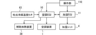
図4に示すように、空調ECU10は、吐出冷媒温度センサ63によって検出された冷媒温度情報を取得する。吐出冷媒温度センサ63は、圧縮機50によって吐出された高圧側における冷媒温度を電気信号として出力するサーミスタである。図6に示すように、第2実施形態の空調装置1は、ヒートポンプ式の冷凍サイクル105を備えている。空調装置1は、空気通路23において第1実施形態におけるヒータコア32の位置に設けられた、冷凍サイクル105の凝縮器51を備えている。つまり、補助加熱装置38は、空気通路23において凝縮器51よりも空気流れの下流に設置されている。冷凍サイクル105の凝縮器51は、内部を流れる冷媒と車室内に送風される空気とを熱交換して空気を加熱する加熱装置である。   As shown in FIG. 4, the air-conditioning ECU 10 acquires refrigerant temperature information detected by the discharged refrigerant temperature sensor 63. The discharge refrigerant temperature sensor 63 is a thermistor that outputs the refrigerant temperature on the high pressure side discharged by the compressor 50 as an electric signal. As shown in FIG. 6, the air conditioner 1 of the second embodiment includes a heat pump type refrigeration cycle 105. The air conditioner 1 includes a condenser 51 of a refrigeration cycle 105 provided at a position of the heater core 32 in the first embodiment in the air passage 23. That is, the auxiliary heating device 38 is provided downstream of the condenser 51 in the air passage 23 in the air flow. The condenser 51 of the refrigeration cycle 105 is a heating device that heats the air by exchanging heat between the refrigerant flowing inside and the air blown into the vehicle interior.

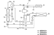
図6を参照してヒートポンプ式の冷凍サイクル105について説明する。図6において、黒塗り太矢印は暖房運転時のサイクル内の冷媒流れを示しており、斜線太矢印は除湿運転時のサイクル内の冷媒流れを示しており、白抜き太矢印は冷房運転時のサイクル内の冷媒流れを示している。凝縮器51は暖房運転時、除湿運転時および冷房運転時において内部を流れる冷媒の放熱作用によって送風空気を加熱する加熱装置として機能する。   The heat pump type refrigeration cycle 105 will be described with reference to FIG. In FIG. 6, black thick arrows indicate the refrigerant flow in the cycle during the heating operation, oblique thick arrows indicate the refrigerant flow in the cycle during the dehumidifying operation, and white thick arrows indicate the cooling operation during the cooling operation. Fig. 3 shows a refrigerant flow in a cycle. The condenser 51 functions as a heating device that heats the blown air by the heat radiation action of the refrigerant flowing inside during the heating operation, the dehumidifying operation, and the cooling operation.

ヒートポンプ式の冷凍サイクル105は、サイクル内を流れる冷媒である、R134a、CO等の状態変化を利用することにより、冷房用の蒸発器55と暖房用の凝縮器51によって冷房、暖房および除湿を行うことができる。 Heat pump type refrigeration cycle 105 is a refrigerant flowing through the cycle, R134a, by utilizing the state change, such as CO 2, cooling the condenser 51 for heating the evaporator 55 for cooling, heating and dehumidifying the It can be carried out.

冷凍サイクル105は、圧縮機50と、凝縮器51と、膨張弁56と、室外熱交換器74と、室外熱交換器74から圧縮機50への冷媒流れを形成する電磁弁57と、冷媒を気液分離する気液分離器53とを備え、これらを配管により環状に接続している。凝縮器51は暖房運転時に圧縮機50によって吐出された冷媒と空気とを熱交換させて空気を加熱する。膨張弁56は暖房運転時に冷媒を減圧する。室外熱交換器74は暖房運転時に膨張弁56で減圧された冷媒を蒸発させる。冷凍サイクル105は、暖房運転時には、圧縮機50、凝縮器51、三方弁70、膨張弁56、分岐部72、室外熱交換器74、電磁弁57、気液分離器53、圧縮機50の順に冷媒が循環する暖房運転経路を有している。さらに、圧縮機50の出口には、圧縮機50によって吐出された高圧側冷媒の温度を検出する吐出冷媒温度センサ63が設けられている。   The refrigeration cycle 105 includes a compressor 50, a condenser 51, an expansion valve 56, an outdoor heat exchanger 74, an electromagnetic valve 57 for forming a refrigerant flow from the outdoor heat exchanger 74 to the compressor 50, and a refrigerant. A gas-liquid separator 53 for gas-liquid separation is provided, and these are connected in a ring by piping. The condenser 51 heats the air by exchanging heat between the refrigerant discharged by the compressor 50 and the air during the heating operation. The expansion valve 56 reduces the pressure of the refrigerant during the heating operation. The outdoor heat exchanger 74 evaporates the refrigerant depressurized by the expansion valve 56 during the heating operation. During the heating operation, the refrigeration cycle 105 includes the compressor 50, the condenser 51, the three-way valve 70, the expansion valve 56, the branch portion 72, the outdoor heat exchanger 74, the solenoid valve 57, the gas-liquid separator 53, and the compressor 50 in this order. It has a heating operation path through which the refrigerant circulates. Further, a discharge refrigerant temperature sensor 63 that detects the temperature of the high-pressure side refrigerant discharged by the compressor 50 is provided at an outlet of the compressor 50.

さらに冷凍サイクル105は、除湿運転時に、圧縮機50、凝縮器51、三方弁70、膨張弁56、分岐部72、分岐部73、電磁弁59、蒸発器55、気液分離器53、圧縮機50の順に冷媒が循環する除湿運転経路を有している。除湿運転経路は、除湿運転時に膨張弁56で減圧された冷媒が室外熱交換器74に流入しないで蒸発器55に流入した後、気液分離器53を経由して圧縮機50に吸入される経路である。   Further, during the dehumidifying operation, the refrigeration cycle 105 includes the compressor 50, the condenser 51, the three-way valve 70, the expansion valve 56, the branch portion 72, the branch portion 73, the solenoid valve 59, the evaporator 55, the gas-liquid separator 53, and the compressor. There is a dehumidifying operation path in which the refrigerant circulates in the order of 50. In the dehumidifying operation path, the refrigerant decompressed by the expansion valve 56 during the dehumidifying operation flows into the evaporator 55 without flowing into the outdoor heat exchanger 74, and is then sucked into the compressor 50 via the gas-liquid separator 53. It is a route.

さらに冷凍サイクル105は、圧縮機50、凝縮器51、三方弁70、分岐部71、室外熱交換器74、分岐部72、分岐部73、電磁弁58、膨張弁54、蒸発器55、気液分離器53、圧縮機50の順に冷媒が循環する冷房運転経路を有している。冷房運転経路は、凝縮器51で送風空気と熱交換した冷媒が膨張弁56を通らないで室外熱交換器74に流入し、膨張弁54で減圧された後、蒸発器55に流入し、気液分離器53を経由して圧縮機50に吸入される経路である。   Further, the refrigeration cycle 105 includes a compressor 50, a condenser 51, a three-way valve 70, a branch 71, an outdoor heat exchanger 74, a branch 72, a branch 73, a solenoid valve 58, an expansion valve 54, an evaporator 55, a gas-liquid It has a cooling operation path in which the refrigerant circulates in the order of the separator 53 and the compressor 50. In the cooling operation path, the refrigerant that has exchanged heat with the blown air in the condenser 51 flows into the outdoor heat exchanger 74 without passing through the expansion valve 56, is depressurized by the expansion valve 54, flows into the evaporator 55, This is a path that is sucked into the compressor 50 via the liquid separator 53.

室外熱交換器74は車両の車室外に配置されており、室外ファンにより強制的に送風される外気と冷媒とを熱交換する。膨張弁56および膨張弁54は固定式の膨張弁、機械式膨張弁で構成してもよい。機械式である場合は感温筒を備え、室外熱交換器74の出口や蒸発器55の出口の冷媒の蒸発状態が適度な過熱度をもつように出口冷媒温度をフィードバックし適切な弁開度によって冷媒流量を制御する温度作動方式を採用する。   The outdoor heat exchanger 74 is arranged outside the cabin of the vehicle, and exchanges heat between the outside air forcedly blown by the outdoor fan and the refrigerant. The expansion valve 56 and the expansion valve 54 may be configured as a fixed expansion valve or a mechanical expansion valve. In the case of a mechanical type, a temperature sensing cylinder is provided, and the outlet refrigerant temperature is fed back so that the evaporation state of the refrigerant at the outlet of the outdoor heat exchanger 74 and the outlet of the evaporator 55 has an appropriate degree of superheat, and an appropriate valve opening degree is provided. A temperature operation system that controls the flow rate of the refrigerant is adopted.

第2実施形態の空調装置1における冷房運転、暖房運転、除湿運転をそれぞれ説明する。空調運転スイッチがオン状態のとき、空調ECU10は圧縮機50を起動し、設定温度と各種センサからの信号とから冷房運転の実行を判定すると、三方弁70の流通方向を分岐部71側、電磁弁58を開状態、電磁弁57および電磁弁59を閉状態に制御する。さらに空調ECU10は、吹出口モードとしてフェイスモードを実施するように吹出切替ドアを制御する。   The cooling operation, the heating operation, and the dehumidifying operation in the air conditioner 1 according to the second embodiment will be described. When the air-conditioning operation switch is on, the air-conditioning ECU 10 starts the compressor 50 and determines execution of the cooling operation from the set temperature and signals from various sensors. The valve 58 is controlled to be open, and the solenoid valves 57 and 59 are controlled to be closed. Further, the air conditioning ECU 10 controls the outlet switching door so as to execute the face mode as the outlet mode.

冷房運転時には、圧縮機50から吐出された高温高圧のガス冷媒は凝縮器51に流入し凝縮器51内を通るときに周囲の空気に吸熱されて冷却されるが、フェイスモードである場合、凝縮器51の周囲を通過する送風量は少なく冷却度合いは大きくない。そして冷媒は、三方弁70によって分岐部71を通過して室外熱交換器74に流入し、室外熱交換器74内を通るときに室外ファンにより送風された空気に吸熱されて冷却され霧状冷媒となる。その後、霧状冷媒は電磁弁58を通った後、膨張弁54で減圧されて蒸発器55に流入し室内用ブロワ20によって空調ケース30内を流れる送風空気から吸熱して蒸発器55内で蒸発し、冷媒は気液分離器53で気液分離された後、圧縮機50に吸入される。蒸発器55で吸熱され冷却された冷風はさらに空気通路23を進んで主にフェイス通路35aを介して乗員の上半身に向けて吹き出されて車室内を冷房する。   During the cooling operation, the high-temperature and high-pressure gas refrigerant discharged from the compressor 50 flows into the condenser 51 and is cooled by being absorbed by the surrounding air when passing through the condenser 51. The air volume passing around the vessel 51 is small and the cooling degree is not large. The refrigerant flows into the outdoor heat exchanger 74 through the branch portion 71 by the three-way valve 70, and when passing through the inside of the outdoor heat exchanger 74, the refrigerant absorbs heat and is cooled by the air blown by the outdoor fan to be atomized. Becomes Thereafter, the mist refrigerant passes through the electromagnetic valve 58, is decompressed by the expansion valve 54, flows into the evaporator 55, absorbs heat from the blast air flowing through the air conditioning case 30 by the indoor blower 20, and evaporates in the evaporator 55. Then, the refrigerant is separated into gas and liquid by the gas-liquid separator 53 and then is sucked into the compressor 50. The cool air absorbed and cooled by the evaporator 55 further travels through the air passage 23 and is blown out toward the upper body of the occupant mainly through the face passage 35a to cool the vehicle interior.

次に暖房運転が行われた場合の冷媒の流れを説明する。空調運転スイッチがオン状態のとき、空調ECU10は圧縮機50を起動し、設定温度と各種センサからの信号とから暖房運転の実行を判定すると、三方弁70の流通方向を膨張弁56側、電磁弁57を開状態、電磁弁58および電磁弁59を閉状態に制御する。さらに空調ECU10は、吹出口モードとして設定温度に応じてフットモード、またはデフロスタモードを実施するように吹出切替ドアを制御する。   Next, the flow of the refrigerant when the heating operation is performed will be described. When the air-conditioning operation switch is on, the air-conditioning ECU 10 starts the compressor 50 and determines the execution of the heating operation from the set temperature and signals from various sensors. The valve 57 is controlled to be open, and the solenoid valves 58 and 59 are controlled to be closed. Further, the air-conditioning ECU 10 controls the outlet switching door to execute the foot mode or the defroster mode according to the set temperature as the outlet mode.

暖房運転時には、圧縮機50から吐出された高温高圧のガス冷媒は凝縮器51に流入し凝縮器51内を通るときに周囲の送風空気に熱を奪われて冷却され凝縮する。そして冷媒は、膨張弁56に流入し、膨張弁56によって室外熱交換器74の出口で冷媒の蒸発状態が適度な過熱度をもつような冷媒圧力に減圧され、また膨張弁56が固定絞り弁である場合は所定の低圧に減圧される。このように膨張弁56によって低圧に減圧された冷媒は分岐部72を通過して室外熱交換器74に流入し、室外熱交換器74内を通るときに室外ファンにより送風された空気から吸熱して蒸発する。室外熱交換器74で蒸発したガス冷媒は分岐部71を経由して電磁弁57を通り気液分離器53で気液分離された後、圧縮機50に吸入される。   During the heating operation, the high-temperature and high-pressure gas refrigerant discharged from the compressor 50 flows into the condenser 51, and when passing through the inside of the condenser 51, heat is taken by surrounding air to be cooled and condensed. Then, the refrigerant flows into the expansion valve 56, and is decompressed by the expansion valve 56 at the outlet of the outdoor heat exchanger 74 to a refrigerant pressure such that the evaporation state of the refrigerant has an appropriate degree of superheat. In the case of, the pressure is reduced to a predetermined low pressure. The refrigerant thus reduced to a low pressure by the expansion valve 56 passes through the branch portion 72 and flows into the outdoor heat exchanger 74. When passing through the inside of the outdoor heat exchanger 74, the refrigerant absorbs heat from the air blown by the outdoor fan. And evaporate. The gas refrigerant evaporated in the outdoor heat exchanger 74 passes through the branch valve 71, passes through the solenoid valve 57, is separated into gas and liquid by the gas-liquid separator 53, and is then sucked into the compressor 50.

暖房運転時に空調ケース30内に取り込まれた低温の空気は、蒸発器55を通過した後、凝縮器51によって加熱され温風となる。そして、暖房運転時のデフロスタモードが行われる場合は、この温風は凝縮器51を通過した後、吹出切替ドアによって開放されたデフロスタ通路34aを通ってフロントウィンドウの内面に向けて吹き出される。また、暖房運転のフットモードが行われる場合は、この温風は凝縮器51を通過した後、吹出切替ドアによって開放されたフット通路37aを通って乗員の足元に向けて吹き出される。   The low-temperature air taken into the air-conditioning case 30 during the heating operation passes through the evaporator 55 and is then heated by the condenser 51 to become hot air. When the defroster mode during the heating operation is performed, the hot air passes through the condenser 51, and is blown toward the inner surface of the front window through the defroster passage 34a opened by the blowout switching door. When the foot mode of the heating operation is performed, the hot air passes through the condenser 51 and is blown toward the feet of the occupant through the foot passage 37a opened by the blowout switching door.

次に除湿運転が行われた場合の冷媒の流れを説明する。空調運転スイッチがオン状態のとき、空調ECU10は圧縮機50を起動し設定温度と各種センサからの信号とから除湿運転の実行を判定すると、三方弁70の流通方向を膨張弁56側、電磁弁59を開状態、電磁弁57および電磁弁58を閉状態に制御する。さらに空調ECU10は、主にデフロスタモードまたはフットモードを実施するように吹出切替ドアを制御する。   Next, the flow of the refrigerant when the dehumidifying operation is performed will be described. When the air-conditioning operation switch is on, the air-conditioning ECU 10 starts the compressor 50 and determines the execution of the dehumidifying operation from the set temperature and signals from various sensors. 59 is controlled to an open state, and the solenoid valves 57 and 58 are controlled to a closed state. Further, the air-conditioning ECU 10 controls the outlet switching door so as to mainly execute the defroster mode or the foot mode.

除湿運転時には、圧縮機50から吐出された高温高圧のガス冷媒は凝縮器51に流入し凝縮器51内を通るときに周囲の送風空気に吸熱されて冷却され凝縮する。冷媒は膨張弁56で減圧され、膨張弁56の出口で冷媒の蒸発状態が適度な過熱度をもつような冷媒圧力に減圧され、その後、室外熱交換器74に流入しないで分岐部72,73を通過して蒸発器55に流入する。冷媒は、蒸発器55の内部では空調ケース30内を流れる送風空気から吸熱して蒸発し、気液分離器53で気液分離されてから圧縮機50に吸入される。   During the dehumidifying operation, the high-temperature and high-pressure gas refrigerant discharged from the compressor 50 flows into the condenser 51, and when passing through the inside of the condenser 51, is absorbed by surrounding blast air to be cooled and condensed. The refrigerant is decompressed by the expansion valve 56, and at the outlet of the expansion valve 56, the refrigerant is depressurized to a refrigerant pressure such that the refrigerant has an appropriate degree of superheat. After that, the branch portions 72 and 73 do not flow into the outdoor heat exchanger 74. And flows into the evaporator 55. The refrigerant absorbs heat and evaporates from the air blown through the air conditioning case 30 inside the evaporator 55, evaporates, is separated into gas and liquid by the gas-liquid separator 53, and is sucked into the compressor 50.

除湿運転では蒸発器55および凝縮器51に冷媒が流れ、空調ケース30内の送風空気はまず蒸発器55で冷却、除湿され、その後に凝縮器51で加熱されて温風となる。この温風は主にデフロスタ通路34aを通ってフロントウィンドウの内面に向かって吹き出され、防曇効果を発揮するとともに車室内を除湿暖房する。   In the dehumidifying operation, the refrigerant flows through the evaporator 55 and the condenser 51, and the blown air in the air conditioning case 30 is first cooled and dehumidified by the evaporator 55, and then heated by the condenser 51 to become hot air. This warm air is mainly blown out toward the inner surface of the front window through the defroster passage 34a, thereby exhibiting an anti-fog effect and dehumidifying and heating the vehicle interior.

第2実施形態の加湿運転に関する制御について図7のフローチャートを参照して説明する。加湿空気供給装置100が備える制御装置は、例えば乗員の操作によって加湿運転スイッチがオンされると図7のフローチャートにしたがった処理を実行する。図7のステップS100、ステップS110における処理は、空調ECU10または加湿ECU11における演算処理部が実行する。   The control relating to the humidification operation of the second embodiment will be described with reference to the flowchart of FIG. When the humidification operation switch is turned on by, for example, an occupant's operation, the control device provided in the humidification air supply device 100 executes a process according to the flowchart in FIG. The processing in steps S100 and S110 in FIG. 7 is executed by the arithmetic processing unit in the air conditioning ECU 10 or the humidification ECU 11.

演算処理部はステップS100で、吐出冷媒温度センサ63による検出信号を取得し、この検出信号に基づいて高圧側の冷媒温度が第2の閾温度以上であるか否かを判定する。高圧側の冷媒温度が第2の閾温度未満であることは、凝縮器51によって加熱された後の空気の温度について、吸着材に吸着されている水分を脱離できる加湿可能温度条件が成立しない場合の一例である。   In step S100, the arithmetic processing unit acquires a detection signal from the discharged refrigerant temperature sensor 63, and determines whether or not the refrigerant temperature on the high pressure side is equal to or higher than a second threshold temperature based on the detection signal. The fact that the refrigerant temperature on the high-pressure side is lower than the second threshold temperature does not satisfy the humidification-possible temperature condition under which the water adsorbed by the adsorbent can be desorbed with respect to the temperature of the air heated by the condenser 51. This is an example of the case.

加熱後の空気温度がステップS100において第2の閾温度未満であると判定した場合はステップS130において前述のステップS40と同様の加湿モード処理を実行する。加湿ECU11は加湿モードの実施後、ステップS140において前述のステップS50と同様の吸湿モード処理を実行する。加湿空気供給装置100は、加湿モードと吸湿モードとを順に実行した後はステップS100に戻り、以降の処理を継続する。   If it is determined in step S100 that the air temperature after the heating is lower than the second threshold temperature, a humidification mode process similar to that in step S40 is performed in step S130. After performing the humidification mode, the humidification ECU 11 executes the same moisture absorption mode processing as in step S50 described above in step S140. After executing the humidification mode and the moisture absorption mode in order, the humidified air supply device 100 returns to step S100 and continues the subsequent processing.

ステップS100で現在の高圧側の冷媒温度が第2の閾温度未満であると判定した場合は、演算処理部はステップS110において吸着材モジュール41において水分を脱離させるために必要な熱量を算出する。演算処理部は、前述のステップS20の処理と同様に、記憶部に記憶された特性マップやデータに基づいて、加湿可能温度を算出しあるいは記憶部に記憶されたデータから加湿可能温度を取得する。演算処理部は、この加湿可能温度と凝縮器51で加熱後の空気温度との温度差を算出し、補助加熱装置38によって加熱される空気の流量と温度差とを用いて、空気の温度をこの温度差分、上昇させるために必要な熱量を算出する。   If it is determined in step S100 that the current refrigerant temperature on the high pressure side is lower than the second threshold temperature, the arithmetic processing unit calculates the amount of heat required for desorbing moisture in the adsorbent module 41 in step S110. . The arithmetic processing unit calculates the humidification possible temperature based on the characteristic map and the data stored in the storage unit, or acquires the humidification possible temperature from the data stored in the storage unit, as in the process of step S20 described above. . The arithmetic processing unit calculates the temperature difference between the humidification possible temperature and the air temperature after heating by the condenser 51, and calculates the temperature of the air using the flow rate and the temperature difference of the air heated by the auxiliary heating device 38. The temperature difference and the amount of heat required to raise the temperature are calculated.

空調ECU10は、ステップS120において、必要な熱量を加湿ECU11と通信して取得し、この必要な熱量を出力できるように補助加熱装置38へ供給する電力を制御して補助加熱装置38を運転する。そして、前述のステップS40、ステップS50と同様のステップS130、ステップS50を順に実行した後、ステップS100に進む。このようにステップS100、S110、S120、S130を順に実行する処理により、凝縮器51が十分な加熱能力を発揮できない状態でも、補助加熱装置38から必要な熱量を得て加熱された空気が加熱用通路40bに流入して、吸着材モジュール41の通過時に吸着材の水分を脱離させることができる。このように吸着材モジュール41に供給される空気が加湿可能温度を満たしているため、吸着材モジュール41の通過時に吸着材が水分を放出できるので、凝縮器51が加熱能力不足である状況でも加湿モードを実施することができる。   In step S120, the air-conditioning ECU 10 acquires the required amount of heat by communicating with the humidification ECU 11, controls the power supplied to the auxiliary heating device 38 to output the required amount of heat, and operates the auxiliary heating device 38. Then, after step S130 and step S50 similar to step S40 and step S50 described above are sequentially executed, the process proceeds to step S100. As described above, by performing the steps S100, S110, S120, and S130 in order, even if the condenser 51 cannot exhibit a sufficient heating capacity, the air heated by obtaining a necessary amount of heat from the auxiliary heating device 38 is used for heating. After flowing into the passage 40b, the moisture of the adsorbent can be desorbed when passing through the adsorbent module 41. As described above, since the air supplied to the adsorbent module 41 satisfies the humidification possible temperature, the adsorbent can release moisture when passing through the adsorbent module 41, so that humidification can be performed even when the condenser 51 has insufficient heating capacity. Mode can be implemented.

第2実施形態の加湿空気供給装置100によれば、加熱装置はヒートポンプ式の冷凍サイクル105に設けられた凝縮器51である。補助加熱装置38は通電によって発熱する電気式ヒータである。制御装置は、加湿可能温度条件が成立していない場合に、凝縮器51を通過後の空気を加熱するように電気式ヒータを制御し、電気式ヒータによって加熱された空気を吸着材に供給するように加湿ユニット4を制御する。   According to the humidified air supply device 100 of the second embodiment, the heating device is the condenser 51 provided in the heat pump type refrigeration cycle 105. The auxiliary heating device 38 is an electric heater that generates heat when energized. The controller controls the electric heater so as to heat the air after passing through the condenser 51 when the humidification possible temperature condition is not satisfied, and supplies the air heated by the electric heater to the adsorbent. The humidifying unit 4 is controlled as described above.

この加湿空気供給装置100によれば、凝縮器51からの放熱量が十分でない状況、例えば冷房運転時や圧縮機50による冷媒吐出量が少ない場合でも、電気式ヒータによって加熱された空気を吸着材に供給して加湿モードを実施できる。これにより、冷房運転時、低出力暖房時、乗員が空調運転を必要としていない場合においても、乗員の要望や車室内の湿度環境改善に寄与する加湿空気供給装置100を提供できる。   According to the humidified air supply device 100, even when the amount of heat radiation from the condenser 51 is not sufficient, for example, during the cooling operation or when the amount of refrigerant discharged by the compressor 50 is small, the air heated by the electric heater is adsorbed. To perform a humidification mode. Accordingly, the humidified air supply device 100 that contributes to the demands of the occupants and the improvement of the humidity environment in the vehicle compartment can be provided even when the occupants do not need the air conditioning operation during the cooling operation, the low-output heating, and the like.

さらに制御装置は、加湿可能温度条件が成立していない場合に、吸着材に供給する空気が加湿可能温度条件を満たす温度になるために必要な熱量を算出し電気式ヒータに通電する電力を必要な熱量を確保する値に制御する(ステップS100,S110,S120)。このステップS100〜S120の処理によれば、電気式ヒータに通電する電力値を、加湿モードを実施可能な必要な熱量に対する不足分に抑えることができる。第2実施形態の加湿空気供給装置100は、電気式ヒータによる電力的なエネルギ消費を抑えた加湿運転の実施によって車両の燃費または電費の低下抑制に寄与する。   Furthermore, when the humidifying temperature condition is not satisfied, the control device calculates the amount of heat necessary for the air supplied to the adsorbent to reach a temperature satisfying the humidifying temperature condition, and requires electric power to be supplied to the electric heater. It is controlled to a value that secures a sufficient amount of heat (steps S100, S110, S120). According to the processes in steps S100 to S120, the electric power value to be supplied to the electric heater can be suppressed to a shortage with respect to a necessary heat amount capable of performing the humidification mode. The humidified air supply device 100 according to the second embodiment contributes to the suppression of a decrease in vehicle fuel efficiency or power consumption by performing a humidification operation in which electric energy consumption by an electric heater is suppressed.

(他の実施形態)
この明細書の開示は、例示された実施形態に制限されない。開示は、例示された実施形態と、それらに基づく当業者による変形態様を包含する。例えば、開示は、実施形態において示された部品、要素の組み合わせに限定されず、種々変形して実施することが可能である。開示は、多様な組み合わせによって実施可能である。開示は、実施形態に追加可能な追加的な部分をもつことができる。開示は、実施形態の部品、要素が省略されたものを包含する。開示は、一つの実施形態と他の実施形態との間における部品、要素の置き換え、または組み合わせを包含する。開示される技術的範囲は、実施形態の記載に限定されない。開示される技術的範囲は、特許請求の範囲の記載によって示され、さらに特許請求の範囲の記載と均等の意味および範囲内での全ての変更を含むものと解されるべきである。
(Other embodiments)
The disclosure of this specification is not limited to the illustrated embodiments. The disclosure embraces the illustrated embodiments and variations thereon based on those skilled in the art. For example, the disclosure is not limited to the combination of the components and elements shown in the embodiment, and can be implemented with various modifications. The disclosure can be implemented in various combinations. The disclosure may have additional parts that can be added to the embodiments. The disclosure includes those in which the components and elements of the embodiments are omitted. The disclosure encompasses the replacement or combination of parts, elements between one embodiment and another embodiment. The disclosed technical scope is not limited to the description of the embodiments. The technical scope disclosed is indicated by the description of the claims, and should be construed to include all modifications within the meaning and scope equivalent to the description of the claims.

前述の実施形態において補助加熱装置38の運転は空調ECU10によって制御される構成であるが、加湿ECU11または車両に搭載されているその他の制御装置によって制御される構成でもよい。   In the above-described embodiment, the operation of the auxiliary heating device 38 is controlled by the air-conditioning ECU 10, but may be controlled by the humidification ECU 11 or another control device mounted on the vehicle.

明細書に開示の目的を達成可能な加湿空気供給装置は、吸湿モード時に吸着材モジュール41を通過させる空気を外気または内気のみに限定する装置ではない。例えば、加湿空気供給装置は、吸湿モード時に外気と内気の混合空気を吸着材モジュール41を通過させる制御処理を実施する装置でもよい。   The humidified air supply device that can achieve the object disclosed in the specification is not a device that limits the air that passes through the adsorbent module 41 in the moisture absorption mode to only outside air or inside air. For example, the humidified air supply device may be a device that performs a control process of passing mixed air of outside air and inside air through the adsorbent module 41 in the moisture absorption mode.

明細書に開示の目的を達成可能な加湿空気供給装置は、補助加熱装置38を空調装置1に内蔵しているが、このような構成に限定されない。加湿空気供給装置は補助加熱装置38を加湿ユニット4に内蔵する構成でもよい。   The humidified air supply device capable of achieving the object disclosed in the specification incorporates the auxiliary heating device 38 in the air conditioner 1, but is not limited to such a configuration. The humidification air supply device may have a configuration in which the auxiliary heating device 38 is built in the humidification unit 4.

前述の実施形態の加湿空気供給装置100が有する加湿ユニット4の構成部品は、一例にすぎない。   The components of the humidifying unit 4 included in the humidified air supply device 100 of the above-described embodiment are merely examples.

明細書に開示の目的を達成可能な加湿空気供給装置に含まれるヒートポンプ式の冷凍サイクルは、前述の実施形態に記載した構成に限定されない。   The heat pump refrigeration cycle included in the humidified air supply device capable of achieving the object disclosed in the specification is not limited to the configuration described in the above embodiment.

前述の実施形態でフローチャートを参照して説明した、加湿ECU11が実行する各処理は、空調ECU10が直接実行する構成としてもよい。   Each process executed by the humidification ECU 11 described with reference to the flowchart in the above embodiment may be directly executed by the air conditioning ECU 10.

前述の実施形態では、吸着材モジュール41として、吸着材を担持させた複数の金属製の板状部材を間隔を開けて積層設置することによって構成されたものを採用した例を説明したが、吸着材モジュール41は、これに限定されない。例えば、波状に折り曲げられたコルゲート板に吸着材を担持させて、このコルゲート板を間隔を開けて積層設置して構成したものを採用してもよいし、断面六角形に形成された通路を有するハニカム部材に吸着材を担持させたものを採用してもよい。   In the above-described embodiment, an example has been described in which the adsorbent module 41 is configured by stacking a plurality of metal plate-like members supporting the adsorbent at intervals and stacking them. The material module 41 is not limited to this. For example, a corrugated plate corrugated in a wavy shape may be used to hold an adsorbent, and the corrugated plates may be stacked and installed at intervals, or may have a passage formed in a hexagonal cross section. A structure in which an adsorbent is carried on a honeycomb member may be employed.

1…空調装置、 4…加湿ユニット
10…空調ECU(制御装置)、 11…加湿ECU(制御装置)
32…ヒータコア(加熱装置)、 51…凝縮器(加熱装置)
38…補助加熱装置、 100…加湿空気供給装置、 105…冷凍サイクル
DESCRIPTION OF SYMBOLS 1 ... Air conditioner, 4 ... Humidification unit 10 ... Air conditioning ECU (control device), 11 ... Humidification ECU (control device)
32: heater core (heating device) 51: condenser (heating device)
38: auxiliary heating device, 100: humidified air supply device, 105: refrigeration cycle

Claims (5)

車室内に送風する空気を加熱する加熱装置(32,51)を有する空調装置(1)と、
前記加熱装置によって加熱された空気を加熱可能な補助加熱装置(38)と、
空気に含まれる水分を吸着材に吸湿することおよび前記吸着材に吸湿された水分を車室内に提供する空気に対して放出することを実施可能な加湿ユニット(4)と、
前記補助加熱装置の運転と前記加湿ユニットの運転とを制御する制御装置(10,11)と、
を備え、
前記制御装置は、前記加熱装置を通過後の空気の温度について、前記吸着材から水分を脱離できる加湿可能温度条件が成立していない場合に、前記加熱装置を通過後の空気を加熱するように前記補助加熱装置を制御し、前記補助加熱装置によって加熱された空気を前記吸着材に供給するように前記加湿ユニットを制御する加湿空気供給装置。
An air conditioner (1) having a heating device (32, 51) for heating air blown into the vehicle interior;
An auxiliary heating device (38) capable of heating the air heated by the heating device;
A humidification unit (4) capable of absorbing moisture contained in the air by the adsorbent and releasing the moisture absorbed by the adsorbent to air provided in the vehicle cabin;
A control device (10, 11) for controlling operation of the auxiliary heating device and operation of the humidification unit;
With
For the temperature of the air after passing through the heating device, the control device heats the air after passing through the heating device when a humidification-possible temperature condition that can remove moisture from the adsorbent is not satisfied. A humidified air supply device that controls the humidification unit so as to control the auxiliary heating device and supply the air heated by the auxiliary heating device to the adsorbent.
前記加熱装置(32)は、エンジンの冷却水が流通するヒータコアであり、
前記補助加熱装置は、通電によって発熱する電気式ヒータであり、
前記制御装置は、前記加湿可能温度条件が成立していない場合に、前記ヒータコアを通過後の空気を加熱するように前記電気式ヒータを制御し、前記電気式ヒータによって加熱された空気を前記吸着材に供給するように前記加湿ユニットを制御する請求項1に記載の加湿空気供給装置。
The heating device (32) is a heater core through which engine coolant flows,
The auxiliary heating device is an electric heater that generates heat when energized,
The controller controls the electric heater to heat the air after passing through the heater core when the humidification-possible temperature condition is not satisfied, and adsorbs the air heated by the electric heater. The humidified air supply device according to claim 1, wherein the humidification unit is controlled to supply the humidified material.
前記制御装置は、前記加湿可能温度条件が成立していない場合に、前記吸着材に供給する空気が前記加湿可能温度条件を満たす温度になるために必要な熱量を算出し、前記電気式ヒータに通電する電力を前記必要な熱量を確保する値に制御する請求項2に記載の加湿空気供給装置。   The controller calculates the amount of heat required for the air supplied to the adsorbent to reach a temperature that satisfies the humidifying temperature condition when the humidifying temperature condition is not satisfied. The humidified air supply device according to claim 2, wherein the supplied electric power is controlled to a value that secures the required amount of heat. 前記加熱装置(51)は、ヒートポンプ式の冷凍サイクル(105)に設けられた凝縮器であり、
前記補助加熱装置は、通電によって発熱する電気式ヒータであり、
前記制御装置は、前記加湿可能温度条件が成立していない場合に、前記凝縮器を通過後の空気を加熱するように前記電気式ヒータを制御し、前記電気式ヒータによって加熱された空気を前記吸着材に供給するように前記加湿ユニットを制御する請求項1に記載の加湿空気供給装置。
The heating device (51) is a condenser provided in a heat pump refrigeration cycle (105),
The auxiliary heating device is an electric heater that generates heat when energized,
The controller controls the electric heater to heat the air after passing through the condenser when the humidification-possible temperature condition is not satisfied, and controls the air heated by the electric heater to the air. The humidification air supply device according to claim 1, wherein the humidification unit is controlled so as to supply the humidification material to the adsorbent.
前記制御装置は、前記加湿可能温度条件が成立していない場合に、前記吸着材に供給する空気が前記加湿可能温度条件を満たす温度になるために必要な熱量を算出し、前記電気式ヒータに通電する電力を前記必要な熱量を確保する値に制御する請求項4に記載の加湿空気供給装置。   The controller calculates the amount of heat required for the air supplied to the adsorbent to reach a temperature that satisfies the humidifying temperature condition when the humidifying temperature condition is not satisfied. The humidified air supply device according to claim 4, wherein the supplied electric power is controlled to a value that secures the required amount of heat.
JP2018131021A 2018-07-10 2018-07-10 Humidifying air supply device Pending JP2020006865A (en)

Priority Applications (1)

Application Number Priority Date Filing Date Title
JP2018131021A JP2020006865A (en) 2018-07-10 2018-07-10 Humidifying air supply device

Applications Claiming Priority (1)

Application Number Priority Date Filing Date Title
JP2018131021A JP2020006865A (en) 2018-07-10 2018-07-10 Humidifying air supply device

Publications (1)

Publication Number Publication Date
JP2020006865A true JP2020006865A (en) 2020-01-16

Family

ID=69150389

Family Applications (1)

Application Number Title Priority Date Filing Date
JP2018131021A Pending JP2020006865A (en) 2018-07-10 2018-07-10 Humidifying air supply device

Country Status (1)

Country Link
JP (1) JP2020006865A (en)

Cited By (1)

* Cited by examiner, † Cited by third party
Publication number Priority date Publication date Assignee Title
CN114593468A (en) * 2022-02-11 2022-06-07 青岛海尔空调电子有限公司 Air conditioner with humidity control function

Cited By (1)

* Cited by examiner, † Cited by third party
Publication number Priority date Publication date Assignee Title
CN114593468A (en) * 2022-02-11 2022-06-07 青岛海尔空调电子有限公司 Air conditioner with humidity control function

Similar Documents

Publication Publication Date Title
JP4232463B2 (en) Air conditioner
JP5831322B2 (en) Vehicle air conditioning system
JP2007069733A (en) Heating element cooling system using air conditioner for vehicle
CN112867616A (en) Air conditioner for vehicle
CN114126900B (en) Air conditioning equipment for vehicle
JP7316841B2 (en) Vehicle air conditioner
JP7655710B2 (en) Air conditioning equipment
JP2012001037A (en) Air conditioning device for vehicle
CN111380256A (en) Heat pump system
JP2004131033A (en) Air conditioner
JP2011037428A (en) Air conditioner for vehicle
JP2004042759A (en) Automotive air conditioners
JP2009166629A (en) Air conditioner for vehicles
CN110049887A (en) Vehicle air attemperation apparatus
JP2015089710A (en) Air conditioner for vehicles
JP5494595B2 (en) Air conditioner for vehicles
JP2009202735A (en) Air conditioning device for vehicle
JP4538846B2 (en) Air conditioner
JP2020006865A (en) Humidifying air supply device
JP3941638B2 (en) Air conditioner for vehicles
CN112543855A (en) Combination valve and vehicle air conditioner using same
WO2022264743A1 (en) Vehicle air-conditioning device
JPH07132728A (en) Air conditioner for automobile
JP2013193466A (en) Vehicle air conditioning device
JP2020006864A (en) Humidifying air supply device